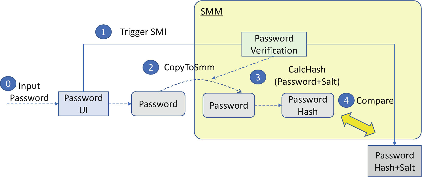
Access control is an important security mechanism to control how the subject accesses the object. The subject here usually means an end user, but the subject could also be a computer or a running process. The object means the computer systems or services. The object could be the hardware, such as a network or a storage device. The object could also be the software, such as an operating system or a database. Finally, the object could be data, such as a file, a registry entry, or memory content. The typical access means to read, write, or execute. The access taxonomy also includes other actions, such as modify, create, delete, append, extend, and so on. Access control can protect the system and resources from unauthorized usage. That is also true in the firmware area.
Subject and Object in Firmware
For the object, the three major security principles are CIA – confidentiality, integrity, and availability. For this topic, what we need to consider is IAA – identification, authentication, and authorization. Identification is the means by which a subject claims to have a specific identity. For example, a user possesses the username, email address, or cellphone number as the identity. Authentication is a process that a system employs to verify the identity of the subject. The three typical means of authentication include (1) use what subject knows, such as a password; (2) use what subject has, such as a smart card; and (3) use what subject is, such as a fingerprint. The identification and the authentication information make up the credentials of the subject. The credentials are compared to the pre-saved credential for this subject. If they match, the subject is authenticated.
Once the subject passes authentication, the system needs to determine which object resources can be accessed by the subject. It can be a predefined access matrix or the security label of the object. If the system determines the subject can access the object, it authorizes the subject.
The identification, authentication, and authorization in firmware may be simplified. For example, if the system only supports one user, user identification can be skipped, and only authentication is required. The authorization can also be simple – just continue the boot.
In the next sections, we will discuss the access control capabilities one by one from the object’s perspective.
Boot Access Control
One of the main roles and responsibilities of a BIOS is to boot the system. The BIOS may add some boot access control to only allow some people to boot the system.
What a User Knows: Password
The BIOS password was introduced early in the history of the PC. Typically, the BIOS supports a user password and administrator (admin) password. When the system boots up, it pops up a dialog to let the end user input a user password. If the user password is correct, the system continues to boot; if not, the system rejects the boot request and resets or shuts down the system. When the end user wants to enter the BIOS setup User Interface (UI) page, the BIOS may pop up a dialog and require the end user to input an admin password. If the admin password is correct, the BIOS shows the setup page to let the user modify the BIOS configuration. If the admin password is not correct, the BIOS does not enter the setup page. This feature is called BIOS password or BIOS user authentication.
Password Storage
The password information must be stored in non-volatile storage. The legacy BIOS typically uses the CMOS RAM as the non-volatile storage (NVS). The standard CMOS RAM only has 128 bytes, and the extended CMOS RAM has another 128 bytes. The CMOS RAM can be read/written via I/O port 70/71 and I/O port 72/73. The memory of the CMOS RAM is maintained by the CMOS battery. If an end user removes the CMOS battery, the CMOS contents are cleared.
The CMOS region is not tamper-resistant. If the password is stored in CMOS, it can easily be attacked. The attacker may write to port 70/71 to update the CMOS RAM directly or clear the CMOS contents by removing the CMOS battery.
Today, the UEFI BIOS no longer uses CMOS RAM for non-volatile storage because of the above-listed security issues. A tamper-resistant storage device must be used to store the encrypted password. Most UEFI BIOS implementations use the flash device as the non-volatile storage for storing the password in UEFI variables. The integrity protection must be guaranteed for the portion of the flash device used for the password.
Password Encryption
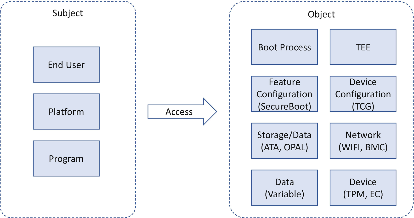
The password should not be stored in the non-volatile storage directly as plain text. Rather, it must be encrypted to maintain its confidentiality so that the password cannot be guessed from the value stored in the non-volatile storage. Typically, the password is encrypted using a one-way function – a hash. This hash (not the password) is stored in the NV storage. The password verification process calculates the hash of the input password with the same one-way function and compares the results between the calculated value and the stored value.
However, just storing the hash of the password is vulnerable to a rainbow table attack. The rainbow table is a database of precalculated hash values for common passwords. With a rainbow table, the attacker just needs to compare the value in the rainbow table and the stored value, which is much faster than hash calculation.
In order to mitigate the rainbow table attack, a salt value should be appended to the password before performing the hash calculation. The password verification process is as follows: get the salt value from the stored area, calculate the hash of the input password and salt, and then compare the calculated value with the stored value. When using the salt value, the fixed rainbow table is useless. The salt should not be a fixed value. It must be as random as possible. For example, each platform should generate the salt value at runtime to make sure it is different between platforms. When a user changes the password, a new salt value can be generated.
The purpose of adding the salt is to make sure that the hash reverse calculation time is closer to that of a brute force attack rather than the much lower time required when using rainbow table lookups.
Another method to increase hash reverse calculation time is to increase the hash iteration count. The hash iteration count is the number of times that the output of the hash function is then used as input and the result is calculated again and again. With a large iteration count such as 1000, the attacker needs to spend much more time to calculate the final result for each password in the dictionary. But the impact to one password calculation is negligible compared to the time the user spends to input the password.
When choosing the one-way function for calculating the hash, a slow hash function should be used, for example, Password-Based Key Derivation Function 2 (PBKDF2). The slower time means that an attacker must spend more time to create the rainbow table to perform the attack.
Password Encryption
Strong Password Enforcement
Even today, people are still inclined to use a simple password, such as 123456. When inputting or provisioning the password, the BIOS should enforce strong password requirements. Examples include the length of the password must be greater than or equal to eight, and also there must be at least one lowercase/uppercase letter, number, and symbol in the password. The BIOS should enforce the strong password requirements and reject weak passwords during provisioning.
Password Update Enforcement
Some computer systems have mandatory password change requests. The user is required to change the password of the system after a period of time, such as three months. This requirement may also be implemented in the BIOS. For example, the BIOS can save the date when the password is created along with the password storage and compare the current date with the stored value. However, it might be a burden for an end user to keep changing the BIOS password. Also, the PC typically doesn’t support a trusted time source, so enforcement of this requirement could be bypassed by an attacker.
Password History
Password history is the hash of previous passwords, such as the three latest passwords or five latest passwords. If the user is asked to change to a new password, some systems check if the new password has been used before by comparing the hash to the previous ones. This is a way to prevent a user from using an old password again. The BIOS may also implement this feature by saving the old password hash and salt data in order to compare the new password hash with them.
Password Retry Limit
In the normal OS or web login pages, the user is only allowed to attempt the password entry a limited number of times, such as three times or five times. After failing the predefined number of iterations, the account will be locked for a while to prevent further attempts.
BIOS password design should use a similar mechanism. If the maximum trying count is reached, the BIOS should stop accepting any further password input. The user needs to reset the system before trying again.
Password Lost
Sometimes the user really forgets their password. Most web pages support the reset password option. After a user clicks the forget password link, the system sends a new link to the end user’s registered email or cellphone. However, it is hard to implement such a solution in the BIOS because it requires a full network stack in the BIOS, a full user registration process, and a dedicated database for BIOS user management. Those are huge burdens for a BIOS implementation and the system manufacturer.
The platform designer must balance between the usability and security of the system. A high-assurance platform may request the platform be sent back to the manufacturer to unlock, such as with a return merchandise authorization (RMA) process. An alternative solution is to let the user submit a password reset request via another machine with the proper user identification and allow the remote administrator to clear password via an out-of-band (OOB) method. A low-end platform may allow the end user to press a special key combination or enter a recovery mode to clear a new password with the assertion of physical user presence if the person who touches the machine is assumed to be the owner of the machine.
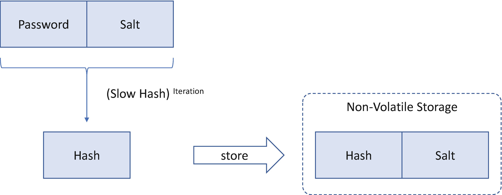
Password Verification
Password verification or update must be in a trusted execution environment, for example, system management mode (SMM) or the early UEFI environment before any third-party code is running. If the password needs to be updated, the old password verification and new password update must happen in the same trusted execution environment, and there must be no interruption between them.
Password Management
The typical BIOS password is stored in the local NV storage area. However, the system password may be managed by a dedicated key server in an enterprise environment. For example, Kerberos is a network authentication protocol used in operating systems such as Windows or Linux. With Kerberos, the client sends the user identity and credential to the remote Kerberos server. The user information and password are stored in the Kerberos server, and the authentication happens in the Kerberos server.
The BIOS may implement the Kerberos client. Once a user inputs the password credential, the BIOS Kerberos client communicates with the remote Kerberos server to finish the user authentication. Care must be taken for the location of the remote Kerberos server. If the server location is saved in the UEFI NV storage region, this data must be protected. Otherwise, the attacker may try to modify the location of the Kerberos server and redirect the action to a fake server.
BIOS Update Mode
If the encrypted user password is saved in the NV storage area, this password information should be preserved during the BIOS update process.
S3 Resume Mode
S3 resume is a resource-constrained execution environment because the primary goal of a S3 resume boot mode is to restore the system configuration and return to the OS as soon as possible. As such, a typical S3 environment does not have the keyboard device driver or the graphic device driver. It is hard to authenticate a user in the S3 resume phase.
Recovery Boot Mode
Recovery boot is another special environment where the UEFI variables might not be available. If the user information and credential are saved to the UEFI NV storage area, they cannot be retrieved during recovery mode. As such, the user authentication may be skipped. If the user authentication is important for an authorized capability, such as continuing to boot, then the authorized capability will be disabled in recovery mode.
What a User Has: Token
Besides passwords, a BIOS may support the device token–based authentication, such as a smart card or a cellphone. The BIOS may include a smart card driver to retrieve the information from the card or include a Bluetooth Low Energy (BLE) driver to exchange messages with a cellphone.
With a password and token, a BIOS may support multifactor authentication (MFA).
What a User Is: Biometrics
The BIOS may also support biometrics-based authentication, such as the fingerprint, if the BIOS includes a fingerprint reader. Or the BIOS may include the ability to perform voice recognition or facial recognition. The issue that needs to be resolved for biometrics is that the BIOS needs to have a way for data sampling, which is not an easy task in the BIOS environment.
Other Considerations
Besides user authentication, the BIOS may consider some other aspects of user management.
User Enroll Enforcement
Some systems or web pages may enforce the enrollment of a username and password at the first boot or at the first web visit. The BIOS password may use this policy as well to enforce user input of a password during the first boot.
Multiple-User Management
A typical BIOS may support the user password and the administrator password. To support multiple users requires more work because the BIOS needs to save the user identity. The purpose of enabling multiple users is to assign different privileges for different users. For example, user A can boot Windows, and user B can boot Linux. If all users have the same authority to boot the OS, then multiple-user support is not required.
Single Sign-On
Single Sign-On (SSO) may be a use case for the multiple users in the BIOS. Once the user authentication is done in the BIOS, the BIOS may pass the user identity and credential to the OS. There are a couple of technical issues that need to be considered. For example, how does the BIOS protect the credential in the memory when the BIOS passes the information to the OS? How does the BIOS handle the situation when the user changes the password in the OS environment? How does the OS trust the information from the OEM BIOS?
Case Study
Now, let’s take a look at some real use cases for boot access control.
EDK II User Authentication
The EDK II BIOS provides a reference implementation for user authentication. A user needs to input a password to enter the BIOS setup UI page to change the BIOS settings, for example, to change the boot option from “boot from hard drive” to “boot from USB device.” As such, only the authorized user is allowed to change such settings.
EDK II User Authentication
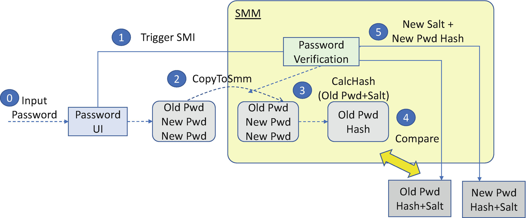
EDK II User Password Update
EDK II User Authorization
In the traditional BIOS, a user is authorized to boot the system, and an administrator is authorized to enter the BIOS setup page and modify the setup options. It is also possible that a BIOS may authorize the user to view the BIOS setup page information or authorize the user to modify some basic BIOS settings, such as the boot options.
Attack and Mitigation
Now, let’s take a look at some real cases for the password attack and mitigation.
Traditional Password Attack
The traditional password attacks include brute force attack against a weak password, dictionary attacks, and a rainbow table attack. There might also be a non-standard password encryption algorithm attack.
- 1)
The password update MUST be in a secure environment, such as SMM, or before EndOfDxe.
- 2)
The password in firmware MUST meet common best password criteria (strength, update, algorithm, retry time, old password check, password lost, and so on).
- 3)
The password in memory MUST be cleared after use. The secret MAY be in a global data region, stack, or heap.
- 4)
The password MUST NOT be hardcoded in the code.
- 5)
If the code needs to compare the plain text password, the code MUST always compare all characters of the string, instead of breaking on the first mismatch. This guarantees that comparison times are always identical whether it is a match or mismatch, preventing timing-based password attacks.
- 6)
Salt MUST be added to the password to resist rainbow table attacks.
- 7)
Hash generation MUST add enough iterations to make sure the hash calculation is slow.
- 8)
Password encryption MUST use a standard encryption algorithm such as PBKDF2, bcrypt. Do not use XOR or any weak hash algorithm.
Some firmware-specific attacks are as follows.
Password Memory
The password is input from the end user via a keyboard. The keystroke is saved in the keyboard-specific memory. If the keyboard memory is not cleared, the attacker can read the whole keyboard memory. In legacy systems, the keystroke is saved in a fixed BIOS data area (BDA). That key buffer in the BDA must be cleared.
The UEFI BIOS does not use BDA. The keystroke is saved in the keyboard driver directly. However, the UEFI BIOS uses Unicode to save the key data. The Unicode buffer needs to be converted to an ASCII buffer and input to the SMM communication buffer. When the final code clears the key buffer, both the Unicode buffer and the ASCII buffer need to be cleared. It could be in a global data region, stack, or heap.
Encrypted Password Storage
The password storage must be tamper-resistant. If the legacy BIOS uses the non–tamper-resistant storage, such as the CMOS region, then the attacker can easily modify the password storage area or clear the password area in order to log into the system.
The UEFI variable storage is tamper-resistant. When the variable is deleted, though, the UEFI variable implementation does not erase the whole variable buffer but instead sets a bit to indicate that the variable is deleted. This is designed because of the hardware attribute of NOR SPI flash. The NOR flash can easily write a bit value of 1 to 0 but cannot write a bit location of value 0 to 1. If the NOR flash needs to set a bit value of 0 to 1, it needs to send an erase command to erase the flash section or block whose size is 4 K or 64 K instead of 1 bit or 1 byte.
If the UEFI solution needs to save the password plain text in the variable region and then delete it, the password content will be in the variable region. As a mitigation, the password plain text should never be put in the variable region.
TEE Access Control
The trusted execution environment (TEE) needs access control. Otherwise, any module can update the TEE content. The details of the TEE will be discussed in Chapter 17.
Feature Configuration Control
The BIOS may allow a user to update the feature configuration. Some features are security related and require special control for the configuration update.
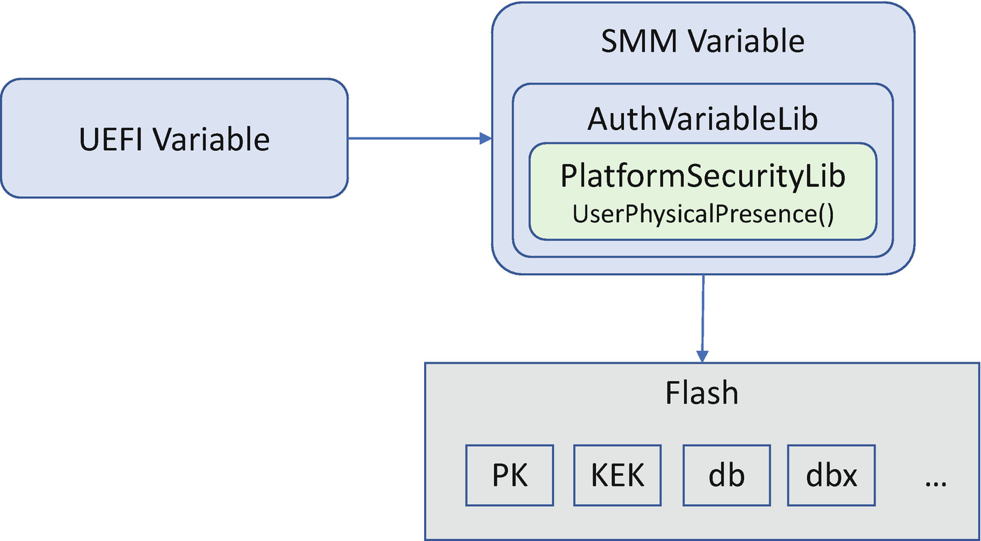
User Physical Presence
In firmware, some feature configuration is saved in a UEFI variable. The update for the configuration requires the user to assert physical presence. This is designed to prevent the configuration being updated by a malicious program automatically.
However, the evidence of the user’s physical presence is a platform-specific design element. Normally, user presence is detected by console input. If there is input from the console, that is good enough to prove a physically present user. For example, the user inputs a password and enters the setup page.
The console could be local or remote. The local console output could be a local graphic device such as Video Graphics Array (VGA), Digital Visual Interface (DVI), High-Definition Multimedia Interface (HDMI), or a local serial port such as a COM port. The remote console output could be via a remote serial port such as Intel Active Management Technology (AMT) Serial Over LAN (SOL) or a remote graphic device such as KVM (Keyboard Video Mouse) redirection. The platform can decide to only treat the local console input as valid for determining physical user presence or both local and remote console inputs as valid. Other implementations of user presence can include a special jumper setting, a special hot key, or a chassis intrusion detection circuit.
UEFI Variable
The UEFI variable is the architectural non-volatile storage that holds firmware configuration settings. In order to prevent malicious access to the UEFI variable, we introduce several ways to control the access to the UEFI variable region. We will discuss these in detail in Chapter 11.
Case Study
Now, let’s take a look at some real cases for the feature configuration control.
UEFI Secure Boot
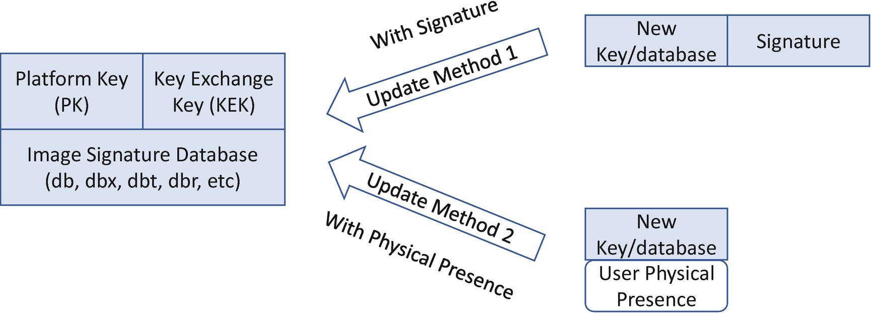
UEFI Secure Boot Signature Database Update
UEFI Secure Boot Variable Component
Attack and Mitigation
Now, let’s take a look at some real cases for the feature configuration attack and mitigation.
PCD-Based Attack
The physical user presence check may happen in the trusted execution environment (TEE), such as system management mode (SMM). As such, the physical user presence function in SMM must not refer to any non-TEE data or function, such as the UEFI Platform Initialization (PI) specification–defined Platform Configuration Database (PCD). The PCD interface is a DXE service only. Referencing the PCD service at SMM runtime causes the typical SMM callout issue. The one possible mitigation is to get the PCD value at the SMM driver entry point and save it as a global variable. Afterward, this global variable can be used during the SMM runtime.
Device Configuration Control
The BIOS may allow a user to update the device configuration. Some features are security related and require special controls for the configuration update.
Physical Presence
As another example of physical presence usage, a device may be configured in the firmware environment only and require access control, such as that provided by a Trusted Platform Module (TPM)’s device configuration and Trusted Computing Group (TCG) storage device configuration. The TPM device may need to be configured in the OS environment, such as clearing the TPM or changing the Platform Configuration Register (PCR) bank. However, making such configuration change in the TPM device requires the platform manufacturer authorization value. This authorization value is only set by the platform firmware. The OS does not know the auth value.
A typical way to achieve this operation is called user confirmation. The end user needs to send the TPM configuration request in the OS, and the platform firmware records this request in non-volatile storage. After the system resets, when the platform firmware finds there is a pending request from the OS, the firmware pops up a User Interface (UI) page to let the end user confirm if this was a real request submitted by the end user. After the end user confirms the request, the platform firmware performs the configuration of the device and resets the system to make the new configuration take effect.
Care must be taken regarding the difference between the physical presence as defined by UEFI secure boot and as defined by TCG TPM devices and TCG storage. A platform may use different ways to implement the physical presence feature for each although the name is the same. For UEFI secure boot, the solution needs proof that the user is present – a simple GPIO setting or a keystroke. For TCG’s physical presence feature, the solution requires that the end user confirm that this is exactly the request submitted from the OS.
Secure Console
If user confirmation is required, the output device and input device must be trusted. A trusted console means the console device connected by the platform BIOS runs before any third-party code, such as that provided by a PCI option ROM or OS application. All the code must be provided by the platform manufacturer. A trusted console might be an 1) integrated device such as a PS2/USB keyboard/mouse without any option ROM, 2) a chipset-integrated video device which is soldered to the system board and whose driver is inside of the BIOS instead of in a separate PCI option ROM flash container, and 3) a third-party video device which is soldered to the system board and whose driver is inside of the BIOS instead of in a PCI option ROM flash container. 4) If a remote console is used as a trusted console, additional authentication may be used, such as a request for an administrator password.
Case Study
Now, let’s take a look at some real use cases for the device configuration control.
TCG Physical Presence
TCG Physical Presence for TPM2.0 and TCG Storage
Opcode | Operation Name | Device | Management Flags | When PP Confirmation Is Required (SetPPRequired XXX Is Set) |
|---|---|---|---|---|
0 | No option | |||
1~95 for TPM2 management | ||||
1 | Enable | TPM | TurnOn | |
2 | Disable | TPM | TurnOff | |
5 | Clear | TPM | Clear | |
14 | Enable + Clear | TPM | Clear or TurnOn | |
17 | SetPPRequiredFor Clear_True | TPM Flags | ||
18 | SetPPRequiredFor Clear_False | TPM Flags | Always | |
21 | Enable + Clear | TPM | Clear or TurnOn | |
22 | Enable + Clear | TPM | Clear or TurnOn | |
23 | SetPCRBanks | TPM | ChangePCRs | |
24 | ChangeEPS | TPM | ChangeEPS | |
25 | SetPPRequiredFor ChangePCRs_False | TPM Flags | Always | |
26 | SetPPRequiredFor ChangePCRs_True | TPM Flags | ||
27 | SetPPRequiredFor TurnOn_False | TPM Flags | Always | |
28 | SetPPRequiredFor TurnOn_True | TPM Flags | ||
29 | SetPPRequiredFor TurnOff_False | TPM Flags | Always | |
30 | SetPPRequiredFor TurnOff_True | TPM Flags | ||
31 | SetPPRequiredFor ChangeEPS_False | TPM Flags | Always | |
32 | SetPPRequiredFor ChangeEPS_True | TPM Flags | ||
33 | LogAllDigests | TPM | ||
34 | DisableEndorsement EnableStorageHierarchy | TPM | TurnOn or TurnOff | |
96~127 for TCG storage management | ||||
96 | Enable_BlockSIDFunc | Storage | EnableBlockSIDFunc | |
97 | Disable_BlockSIDFunc | Storage | DisableBlockSIDFunc | |
98 | SetPPRequiredFor Enable_BlockSIDFunc_True | Storage Flags | ||
99 | SetPPRequiredFor Enable_BlockSIDFunc_False | Storage Flags | Always | |
100 | SetPPRequiredFor Disable_BlockSIDFunc_True | Storage Flags | ||
101 | SetPPRequiredFor Disable_BlockSIDFunc_False | Storage Flags | Always | |
>=128 for TCG vendor-specific extension | ||||
Operations 1~95 are for TPM2 management. All of these commands need platform auth and must be executed by the platform firmware. The physical presence check can prevent the TPM2 device from being compromised by a malicious program.
Operations 96~127 are for TCG storage devices. The physical presence check can prevent a malicious entity from taking ownership of a SID credential that is still set to its default value of MSID.
- 1)
Physical presence control: A platform operator who is physically present at the platform must press a key to authorize an action.
- 2)
Software control: An OS or other software controlling the system manages the device without the need for a physically present operator to approve changes.
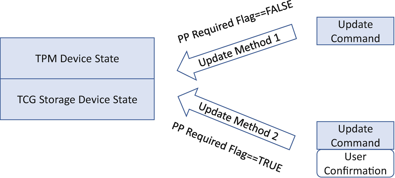
TCG PP Configuration Update
The TCG Physical Presence (PP) also defines a set of operations to control the two options. For example, the user may perform the SetPPRequiredForClear_False operation and confirm the action. Then, the next time the software sends the TPM clear command, no user confirmation is required.
TCG PP Configuration Component Design
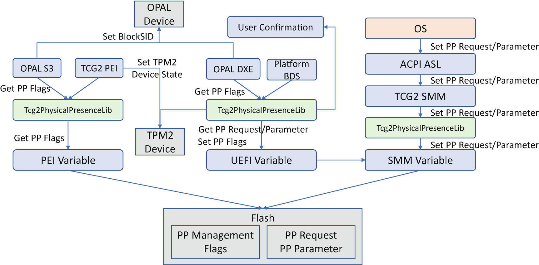
According to the TCG PP specification, the PP request is submitted from the OS via the ACPI ASL interface. Typically, the ASL generates a software SMI whose handler records the PP request and its parameters to the PP request variable. On the next boot, BDS processes the TCG PP request via the Tcg2PhysicalPresenceLib. The Tcg2PhysicalPresenceLib pops up a UI to let the user confirm the request based upon the request. Once the PP request is confirmed, the Tcg2PhysicalPresenceLib has two ways to process the PP request. 1) If the request takes effect once, such as to clear TPM or set the TPM PCR bank, the PP library sends the command to the device immediately. 2) If the request takes effect on every boot, such as setting the BlockSID auth, disabling the TPM, or changing PPRequiredForXXX flags, the PP library records the information in the PP flags variable. Whether or not there has been a PP request, the PP flags variable should always be locked. On every subsequent boot, the TCG2 PEIM and the OPAL storage driver consume the PP flags variable information in order to set the TPM2 device state and set the BlockSID auth.
Attack and Mitigation
Now, let’s take a look at some real use cases for the device configuration attack and mitigation.
PP Flags Variable Attack
The PP flags variable records the expected device state and the need to request user confirmation. An attack may try to update the variable to bypass the user confirmation. Ideally the PP flags variable should be locked on every system boot.
One vulnerability we have seen before is when the PP flags variable is not locked during S4 resume. Because the TCG PP specification requires skipping the TCG PP process on the S4 resume path, the PP library might accidentally skip everything during S4 resume including locking the TCG PP flags variable.
Another vulnerability is during S3 resume. The OPAL PEI S3 driver uses a special read/write variable to record the TCG BlockSID request. As such, the attacker may change that variable to cause the driver to modify the TCG OPAL device state.
The mitigation is to make any TCG PP variable a read-only variable and lock the PP variable in every possible boot mode.
Storage Access Control
Storage Device Binding
Mechanism | PROs | CONs | Solution | Example |
|---|---|---|---|---|
Bind to a platform (provided by TPM) | User interaction is not required to unlock the disk. | Any user can access the storage if they can touch the platform hardware. | The OS supports full disk encryption with the key sealed in the TPM with PCR. | Microsoft TPM-based BitLocker. |
Bind to an end user (provided by the storage device) | Different users cannot access the disk. | User interaction is required. | The storage device supports the password-based unlock. | ATA password, TCG OPAL password. |
We have discussed the Windows BitLocker solution for binding the storage to the platform in Chapter 7. Now we will focus on the second part – binding the storage to the end user.
Hard Drive Password
The hard drive password solution must follow all the same password best practices as the user password authentication solution. For example, the solution should not save the password plain text in the NV storage area. The password memory must be cleared after verification. If the password verification fails, the system should reset instead of continuing to boot. The only difference is that the entity that does the verification is the hard drive hardware rather than the platform firmware.
Fast Boot Impact
The hard drive password unlock should happen in the BIOS. As such, all locked hard drives should be unlocked; then all hard drives should be discovered and connected in the BIOS.
Because the BIOS does not know if a hard drive needs to be unlocked or not, the BIOS has to connect all hard drives in the system irrespective of whether a password unlock is needed. That brings a burden for the BIOS fast boot feature because the BIOS fast boot requires that it only connect the devices required for the OS boot. Connecting any additional device adds unnecessary additional boot time.
Unlock in a Warm Reset
Ideally the hard drive is locked after reset, and password verification is required during the next boot. However, if a platform reset is a warm reset, the hard drive might or might not be reset. Without reset, the hard drive remains in the unlocked state. In this case, there is no way to let hardware verify the password.
On the other hand, there does need to be a way to verify the password because the password needs to be saved by the BIOS in order to unlock the drive during S3 resume. This is due to the fact that there is no console during S3 resume by default. As such, asking a user to input a password during S3 resume is not a desired option.
- 1)
Hardware solution: If the device can support the lock command, the BIOS can send the lock command at first; then try to use the new password to unlock.
- 2)
Software solution: If the device does not support the lock command, the BIOS can save the encrypted verified hard drive password to the NV storage and compare the encrypted new password with the stored value in the NV storage.
Auto Unlock in S3
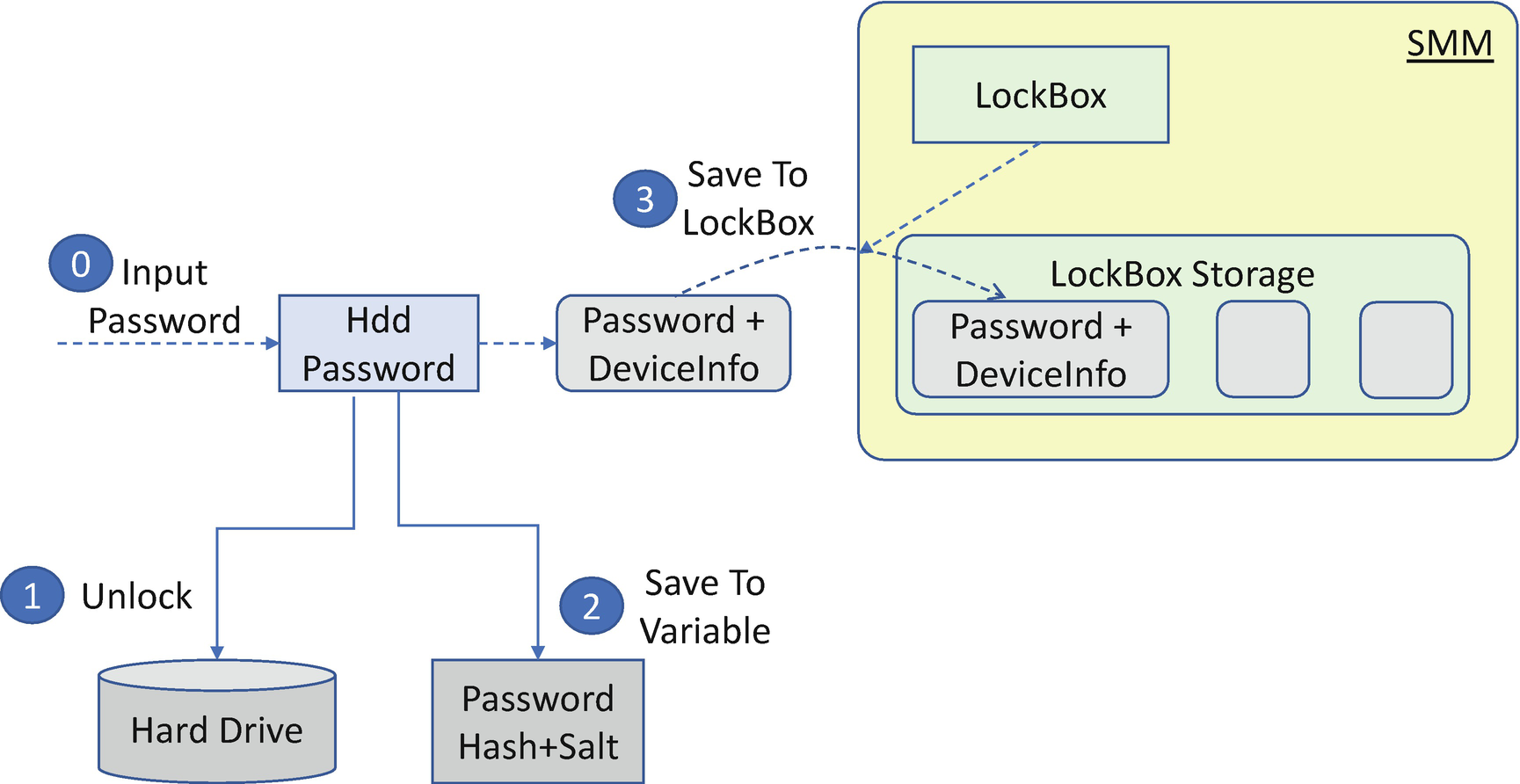
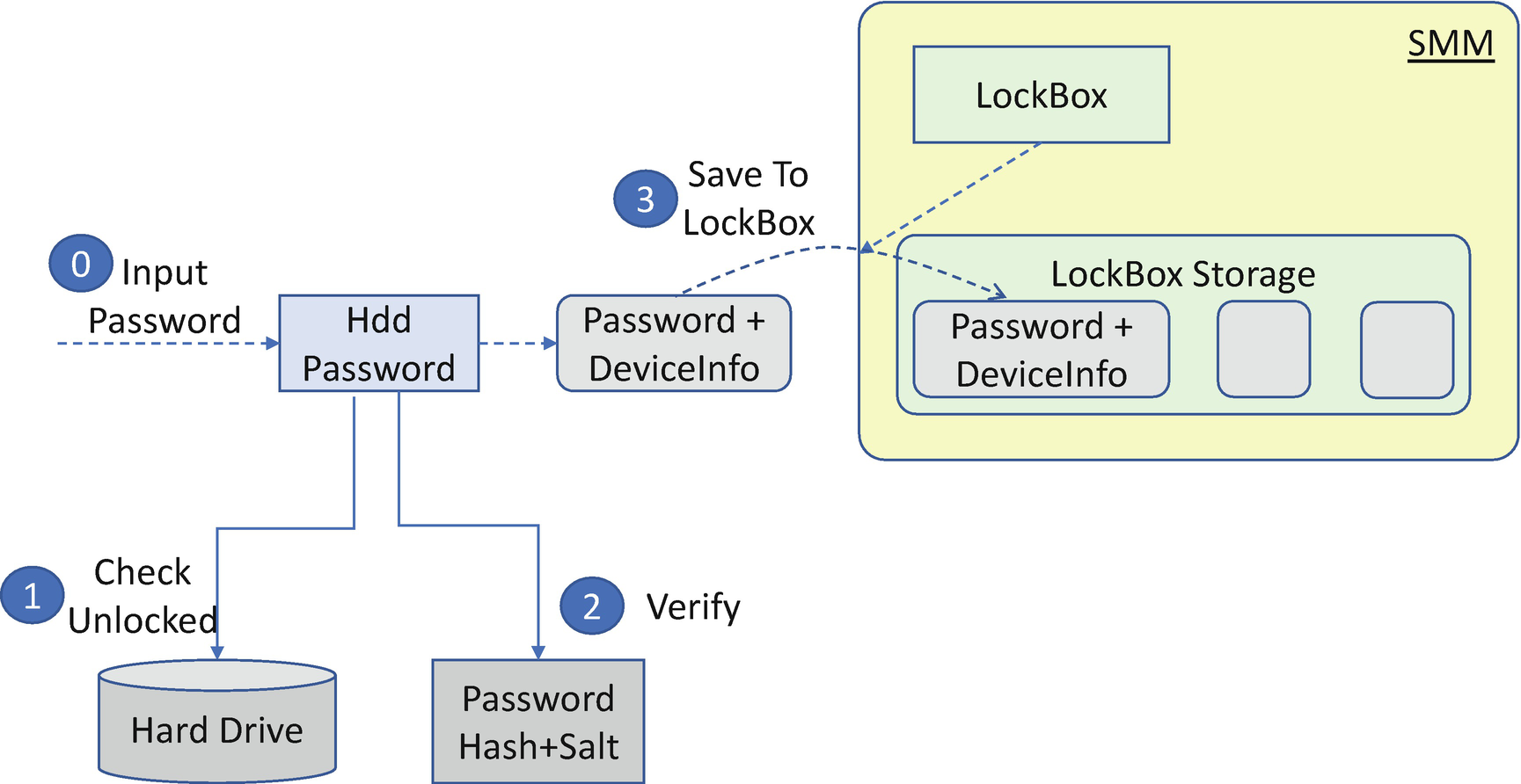
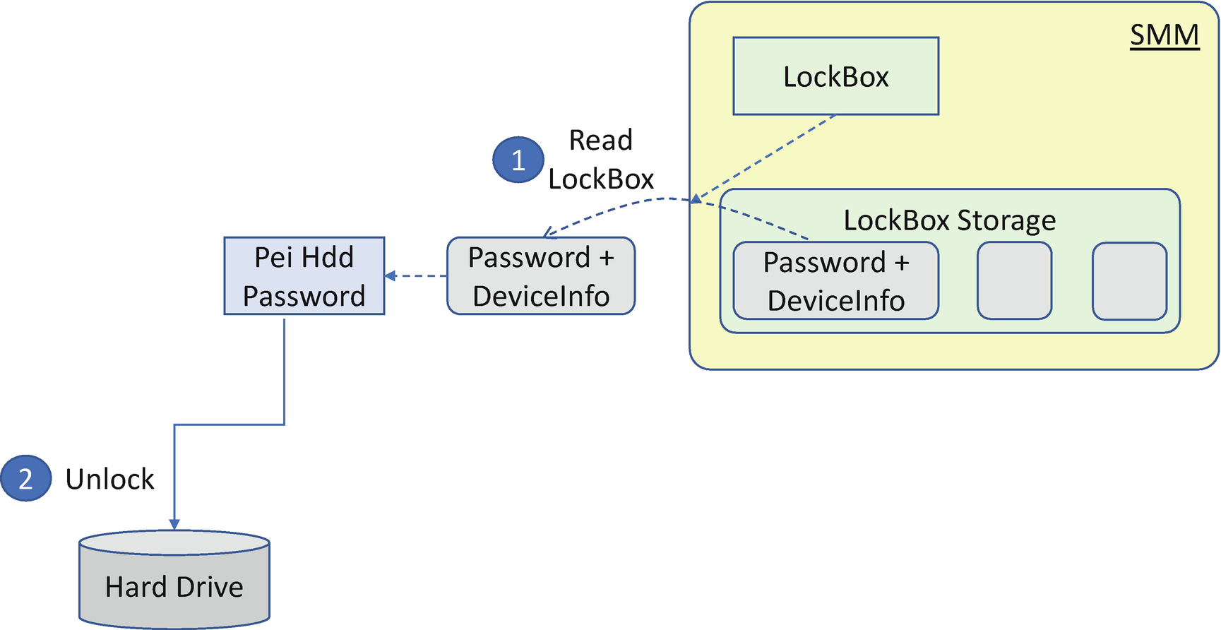
Most platform BIOS do not have a User Interface during S3 resume. However, the hard drive is locked in the S3 state because of the power loss. As such, the BIOS needs to have a secure way to save the hard drive password during the normal boot and send the unlock command during S3 resume. In order to achieve this, the solution needs to do the following: 1) always get the password during a normal boot, and 2) save the password in a secure place with confidentiality and integrity protection.
We have discussed the solution to always get the password in a normal boot in a previous section. Even if the hard drive is unlocked, we still have a way to verify the password.
The secure place to store the password could be the Trusted Execution Environment (TEE) or any other environment. EDK II BIOS designed the “LockBox” concept to abstract such a secure place. Any driver can put some data into the LockBox during a normal boot and restore the same content during S3 resume. The LockBox implementation can guarantee the data integrity (no lower-privilege driver is allowed to modify the contents) and the data confidentiality (no lower-privilege driver is allowed to read the contents). We have discussed LockBox in Chapter 9.
Runtime D3 impact
A storage device may support the runtime D3 feature. Runtime D3 means putting the device into the D3 hot/cold low-power state while the rest of the system is still in the S0 working state. If the hard drive is in a D3 cold state, it loses power and it is locked. If the system needs to bring the hard drive back to the D0 working state, there must be an entity to input the password and unlock it.
This work can be done by the BIOS or by the operating system. But both solutions have limitations. If the BIOS needs to unlock the hard drive, the runtime BIOS code (SMM) needs to access the device registers. There is a potential MMIO resource conflict between the BIOS and the OS because the OS owns all system resources at runtime, including the MMIO resources. Another potential conflict is DMA access because sending a command to the hard drive needs to use DMA. However, the OS owns the DMA/IOMMU controller. If the OS needs to unlock the hard drive, then the end user is required to input the hard drive password again at OS runtime because the OS does not know the password that the user input while in the BIOS. This adds an extra burden on the end user.
Maybe the best solution is to disable the hard drive password feature for the devices that support runtime D3.
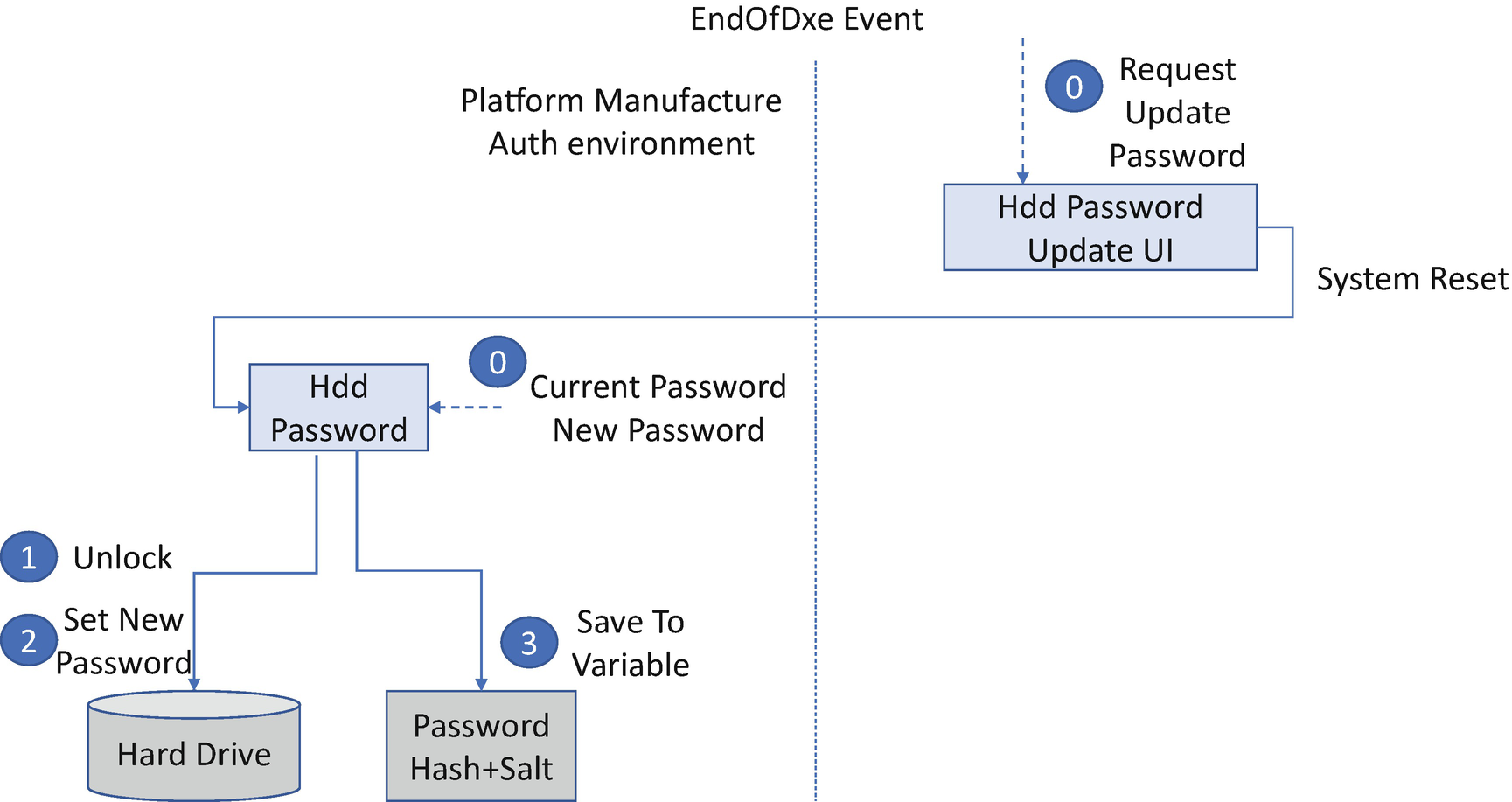
Password Update
The user may update the hard drive password. This work must be done in a trusted execution environment. If the system BIOS does not treat the BIOS setup User Interface (UI) as a trusted execution environment, the system BIOS cannot let the user perform the password update there.
One possible solution is to let the user submit the password update request in the BIOS setup UI and then reboot the system. During the next boot, the password driver can pop up a dialog box to let the end user change the password.
User Password vs. Master Password
An end user needs to set a hard drive user password. With the user password, the hard drive is unlocked, and the end user can use the data on the disk.
An administrator may set a hard drive master password as well. With the master password, the administrator can delete the user password and erase the data on the disk. But the administrator cannot read the disk data with the master password. This is purposely designed for the scenario that a user returns the disk to an administrator in the enterprise still locked with the user password.
Retry Count
The hard disk drive maintains a password attempt count internally. Once the retry count is reached, the device will return a command abort for any further access to the device until next boot.
Hard Drive Freeze
Sometimes, the BIOS does not want to set a hard drive password and also does not want the password to be set by the operating system. As such, the BIOS needs to send a Freeze Lock command to freeze the disk security features, thus preventing a malicious program in the OS from setting a random password to the hard drive.
Secure Console
Hard drive unlock has similar strict secure console requirements.
Case Study
Now, let’s take a look at some real use cases for storage access control.
ATA Password
ATA/ATAPI Security Commands
ATA/ATAPI Command | Usage |
|---|---|
SECURITY SET PASSWORD | Set a new user/master password for the hard drive. |
SECURITY UNLOCK | Unlock the hard drive. |
SECURITY ERASE PREPARE | Erase the user content. |
SECURITY ERASE UNIT | Prepare for the erase command. |
SECURITY FREEZE LOCK | Freeze the disk and prevent password setting attack. |
SECURITY DISABLE PASSWORD | Disable hard drive password. |
HDD Password Solution in Cold Reboot
HDD Password Solution in Warm Reboot
HDD Password Solution in S3 Resume
HDD Password Update
TCG Storage Password
The ATA/ATAPI command set is only for ATA/ATAPI devices. However, there are other storage devices such as those attached to other buses, such as the Small Computer System Interface (SCSI), Universal Serial Bus (USB), Non-Volatile Memory Express (NVMe), and so on. How can we support the similar security features on those storage devices? The Trusted Computing Group (TCG) storage group defines common security services that allow all storage devices to support the storage device password.
- 1)
Data confidentiality and access control over TPer features and capabilities, including the data area readability and writability
- 2)
TPers and hosts’ bilateral enrollment and connection for the permissions and authorizations
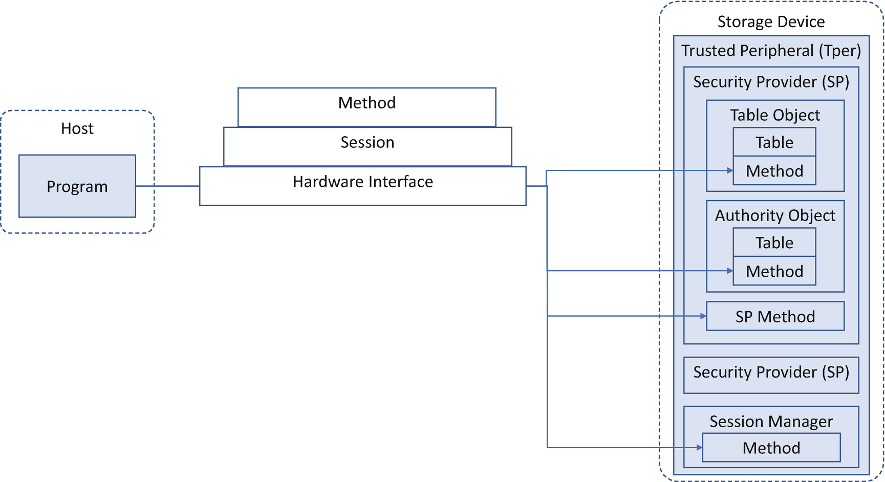
TCG Storage Device Architecture
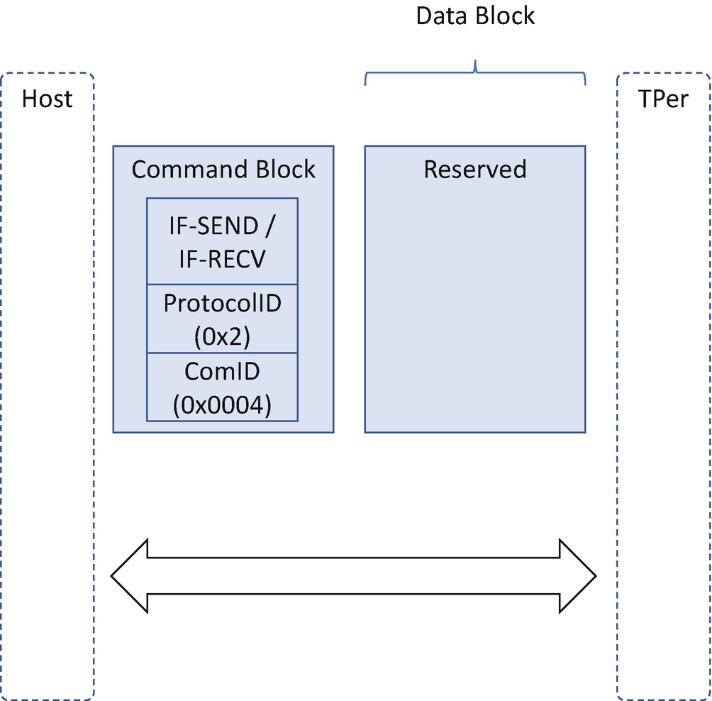
The only way to communicate with an SP is via a session. Only the host is able to open a session. Methods are invoked within sessions. In order to start a session, the host needs to indicate the 8-byte SP Unique Identifier (UID) – which SP the host wants to communicate – the 8-byte Host Signing Authority UID, and the host challenge data for the Host Signing Authority. Within the session, the host may invoke the method provided by the SP, and the host needs to indicate the 8-byte invoking ID (such as session manager, this SP, table UID, object UID) and 8-byte method ID – the method provided by the invoking ID and the method parameters.
- 1)
TCG storage unlocks.
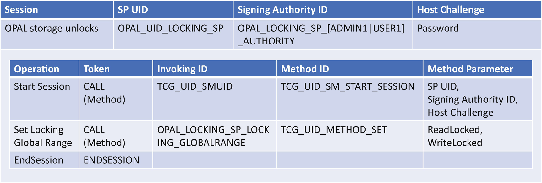
TCG Storage Unlock
Compared with ATA security features, the TCG defines a more complicated method of host/device communication. The benefit of this approach is that device functionality is abstracted as the method within the SP.
- 2)
TCG storage set admin password.
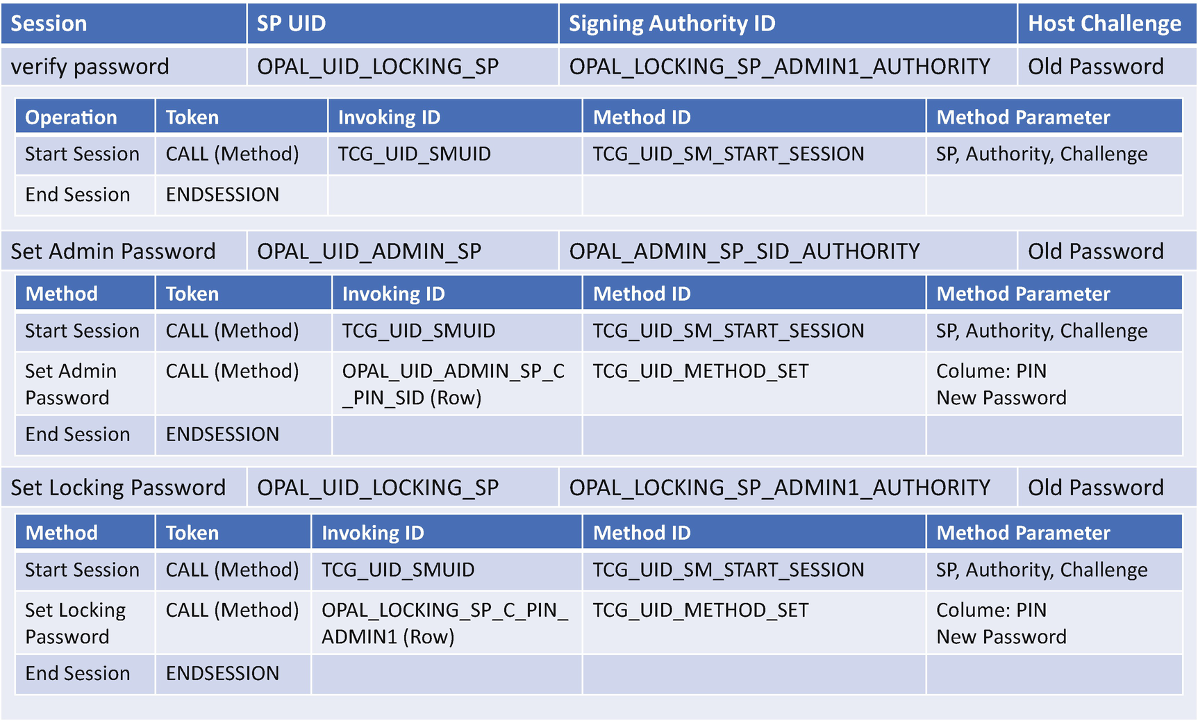
TCG Storage Set Admin Password
Second, after the verification passes, the TcgOpalPassword driver creates the second session with OPAL_UID_ADMIN_SP with the OPAL_ADMIN_SP_SID_AUTHRITY and the old password. After the session is created, the TcgOpalPassword driver invokes the CALL method with invoking ID being OPAL_UID_ADMIN_SP_C_PIN_SID and the method ID being TCG_UID_METHOD_SET. The parameter is the PIN column number and the new password. This session is to update the PIN in the ADMIN_SP.
Third, the TcgOpalPassword driver updates the PIN for the LOCKING_SP. It creates a session with OPAL_UID_LOCKING_SP again and invokes a new CALL method with invoking ID being OPAL_LOCKING_SP_C_PIN_ADMIN1 and method ID being TCG_UID_METHOD_SET. The parameter is the PIN column number and the new password.
After those steps, the PIN is updated in both the ADMIN_SP and the LOCKING_SP.
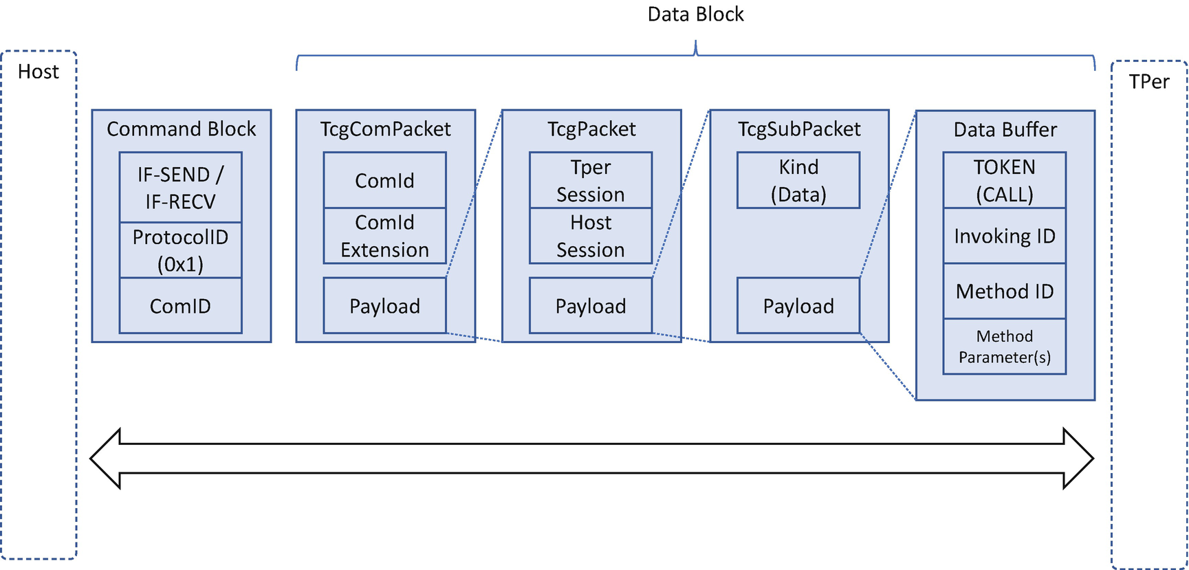
TCG Storage Interface Data Block
TCG Storage – SID (Secure Identifier)
The Security Identifier (SID) authority is used by TPer owner, also known as the storage device owner, to authenticate to the Admin SP. After getting the device, the user may take the ownership by changing the SID Personal Identification Number (PIN). Figure 10-15 shows how to set the admin password.
TCG Storage – MSID (Manufactured SID)
When a TCG Storage device is shipped, it may carry a Manufactured SID (MSID) credential set at the manufacturing time by the storage device vendor. The MSID does not have any associated authority and it may be read by anybody. The MSID value can be used as the device initial SID value – the device owner’s password. Once the user takes ownership, the user may input the MSID value to the SID authority in the admin SP then set a new SID value to replace the default MSID value.
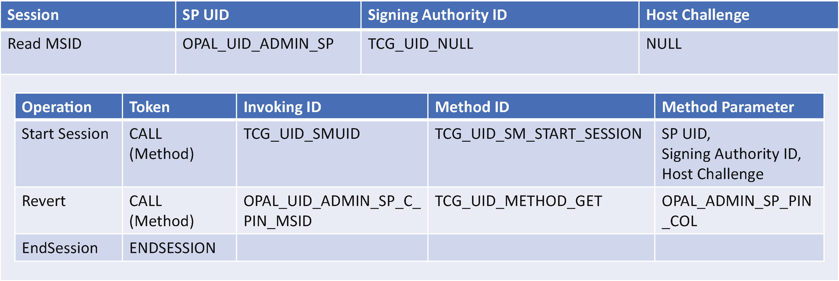
TCG Storage Read MSID
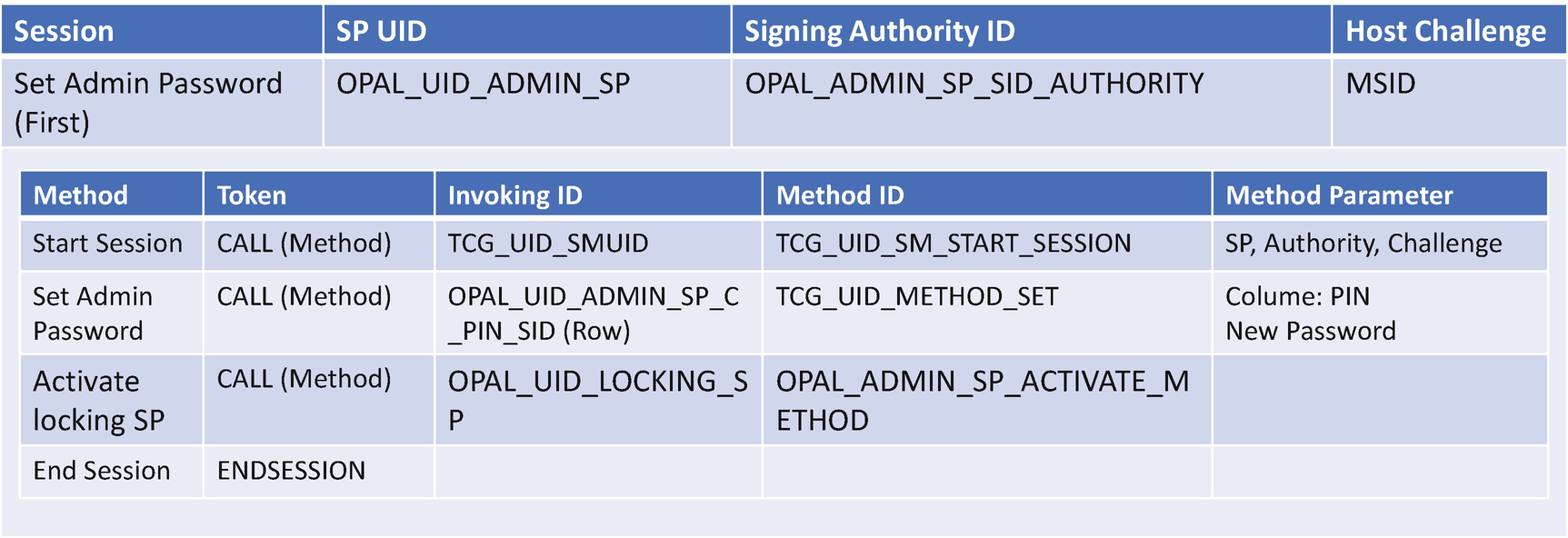
TCG Storage use MSID to set first Admin password
After that, in the same session the OpalPassword invokes the CALL method with invoking ID being OPAL_UID_LOCKING_SP and method ID being OPAL_ADMIN_SP_ACTIVATE_METHOD, to activate the locking SP.
TCG Storage – BlockSID
TCG Storage BlockSID
From the BIOS perspective, there is a policy that determines whether the BIOS needs to send the BlockSID command or not. TCG storage reuses the TCG Physical Presence solution to process the BlockSID enable/disable request from the OS and uses a read-only variable to store the policy information. See Table 10-1.
TCG Storage – PSID (Physical Presence SID)
If a user or an admin forgets the TCG storage password and still wants to use the device, he or she may use the Physical Presence SID (PSID) revert. The PSID revert resets the SID PIN to the default MSID and may erase all media encryption keys. As a consequence, the user data is destroyed. The PSID feature was designed so that if the user forgets the password, the user may input the PSID credential value to revert the device. The PSID delivery method is vendor specific. One simple solution is to print the PSID credential value on the device label. Any physical user who can touch the device can get the PSID value.
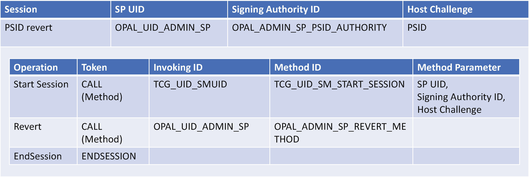
TCG Storage PSID revert
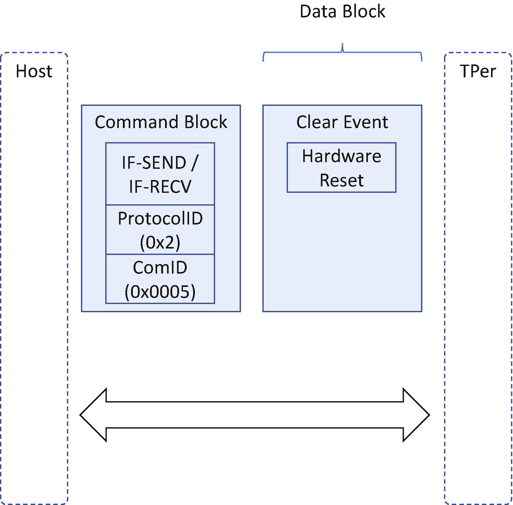
TCG Storage – TPer Reset
The platform reset attack may get the secret in the memory. In order to mitigate the reset attack to memory, the TCG defines the Memory-Only Reset (MOR) feature to inform the BIOS to clear memory after an abnormal reset. We have discussed that feature in Chapter 7. The storage device may experience a similar platform reset attack because the protected region may be unlocked after the platform reset. In order to mitigate the attack to the storage device, the BIOS needs to issue a TPer Reset command once the BIOS detects the MOR request. After TPer reset, all protected regions are locked again.
TCG Storage TPer Reset
Attack & Mitigation
Now, let’s take a look at some real use cases for the attack for the storage access control and mitigation.
No HDD Freeze Lock / TCG BlockSID
The HDD Freeze Lock and the TCG BlockSID feature are designed to prevent the attack by a malicious program in the operating system (OS) to take ownership of a device. The OS may want to take ownership of the storage device, or the OS might not take ownership by setting a new password to the storage device. This is a policy set by the OS. The TCG defines the physical presence (PP) interface for the policy passing from the OS to the BIOS via the ACPI method. Similar to the TPM PP interface, the storage PP interface also saves the storage management flag to a UEFI variable. This UEFI variable must be locked in any boot mode, including normal boot and S3 resume.
One vulnerability we have found before is that the BlockSID command is only sent in a normal boot, but not sent during S3 resume. Then the malicious program just needs to trigger an S3 resume then takes owner control of the device. The TCG storage driver should consume this storage management flag variable to send the BlockSID command in S3 resume as well if necessary.
No TCG TPer Reset
TPer Reset commands should be sent when the BIOS detects the MOR request. In order to issue a TPer reset to all hard drives, the platform needs to detect all the hard disks and restart all of them. However, some BIOSes may implement a fast boot path and only connect the boot device. That brings the risk that the TPer reset is not sent to the rest of the devices. The mitigation is that once the platform BIOS detects the MOR request, the platform BIOS quits the fast boot path and enumerates all the hard drives. Then the MOR driver discovers all hard drives and sends the TPer reset to all of them.
Network Access Control
A UEFI BIOS may include a full TCP/IP network stack to support the Preboot Execution Environment (PXE) boot or HTTP boot. Network access control may be needed in this case.
Case Study
Now, let’s take a look at some real cases for network access control.
WIFI network
The physical layer of the network could be a wired network device or a wireless network such as Wireless-Fidelity (WIFI). In order to support connecting to a WIFI network, the user may be asked to input credentials for authentication. In client mode, the WIFI network uses the pre-shared key (PSK), also known as WIFI password, for authentication. In enterprise mode, the WIFI network uses IEEE 802.1X port authentication and the Extensible Authentication Protocol (EAP) authentication method.
For the PSK use-case, the user needs to input the WIFI password to connect the network. The question is if the BIOS needs to store the WIFI password. On the one hand, if the BIOS does not store any WIFI password, then the user is required to input the WIFI password whenever he or she wants to connect to the same WIFI network. That is a different user experience compared with the OS environment. On the other hand, if the BIOS stores the WIFI password in a UEFI variable or a configuration file, the plain text data may be exposed to any program. This solution may bring a security concern. The BIOS may choose to encrypt the WIFI password with a key. Now the problem is how to get the key in the boot. If the user is asked to input the key, we go back to the original problem – user interaction is required.
There is no simple answer on how to handle a WIFI password in the BIOS. The solution must balance the usability and the security.
Bluetooth
A UEFI BIOS may include Bluetooth support, such as a Bluetooth keyboard or mouse. Bluetooth device connection may also require authentication, such as numeric comparison, passkey entry, or an out-of-band mechanism. Once the device and host pairing is successful, a pairing key is generated. The UEFI implementation may choose to save the pairing key for future use. However, the integrity and the confidentiality of the pairing key might be a concern if the platform saves the pairing key plain text to a UEFI variable. That should be considered when implementing a Bluetooth auto-reconnection feature.
TCP/IP Network Security
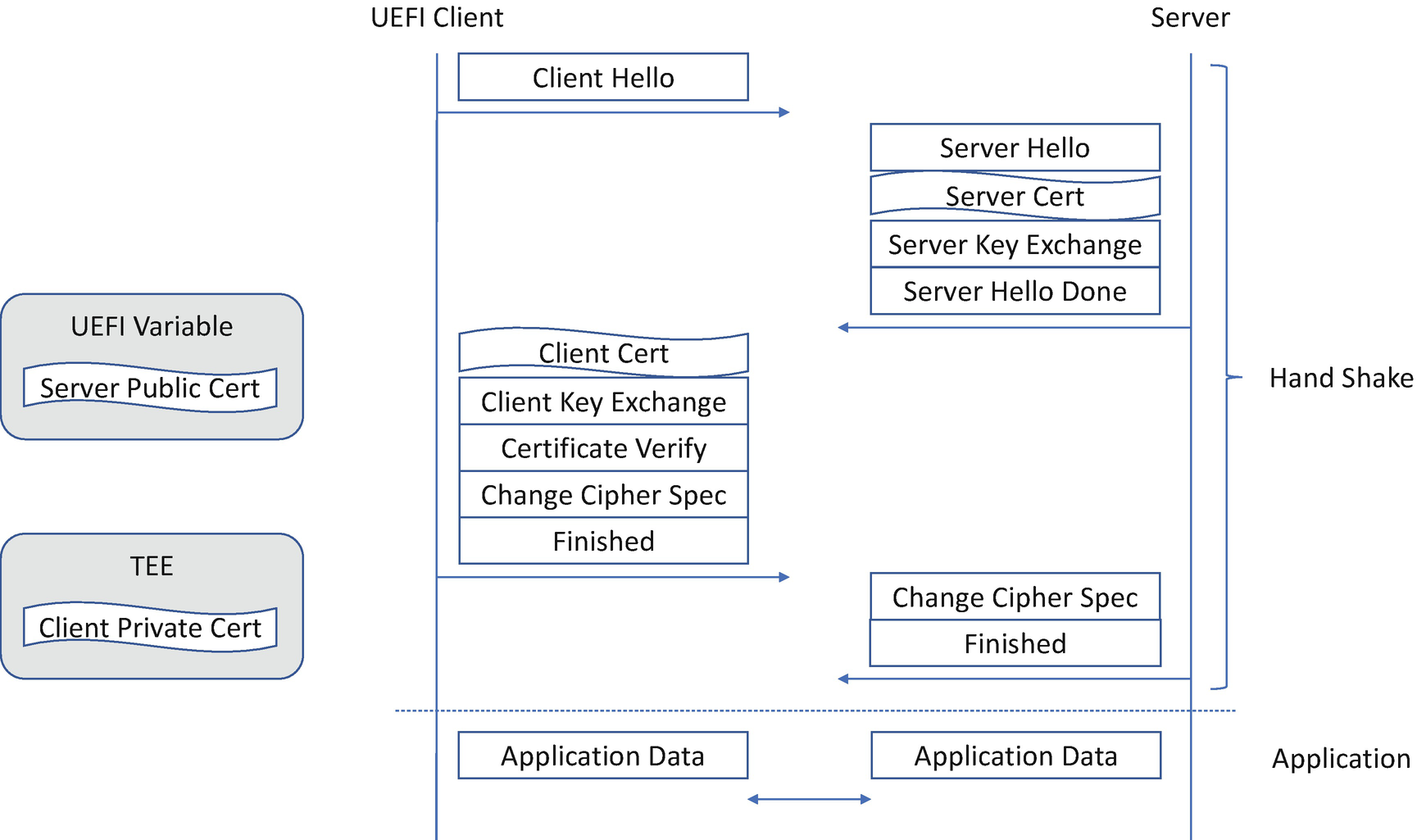
TLS Handshake
Attack & Mitigation
Now, let’s take a look at some real use cases for the attack for the network access control and mitigation.
Private Certificate Storage Attack
The management of the private certificate or private key in the UEFI BIOS is always a big challenge. If it is saved in the UEFI Variable region, it becomes a problem because the UEFI Variable only provides the integrity support but not confidentiality support according to the UEFI Specification. Adding the certification management in the UEFI Variable might be an overhead because we may enable data encryption with the user password, which means user interaction is required. As an alternative, we can leverage the TPM non-volatile storage and key hierarchy to manage the private key, with the option to bind to a platform instead of a user. Another choice is to let a TEE maintain the private key, such as the Intel Converged Security and Management Engine (CSME). Care must be taken to keep the key service in the BIOS only accessible before any third-party code running and close the service before booting into the OS.
TLS Hostname Attack
The network security in the UEFI BIOS supports peer authentication. The UEFI client side may need to authenticate the server. One TLS issue in EDK II that has arisen before is about the peer hostname verification. Here is the issue: The server certificate has a Common Name (CN) for the subject. This name is used to match the hostname of the server site. The expected behavior from the client side is 1) to verify the hostname (identification), 2) to verify the certificate (authentication). The early version of UEFI TLS only verified the server certificate, but not the hostname, which brings in the potential of a man-in-the-middle attack.
Device Access Control
One of the main roles and responsibilities of a BIOS is to initialize the devices on the motherboard. Different devices may have different mechanisms for the device access control.
Case Study
Now, let’s take a look at some real use cases for the device access control.
TPM2 Hierarchy Auth Value
- 1)
Platform hierarchy – Controlled by the platform manufacturer. It is used by the platform BIOS.
- 2)
Storage Hierarchy – Controlled by the platform owner. The owner could be an end user or the IT administrator. It is used for the key or data storage.
- 3)
Endorsement Hierarchy – Controlled by the privacy administrator, who might be an end user. It is used for privacy sensitive actions, such as providing device attestation.
During system boot, the platform BIOS needs to take over the platform hierarchy by sending TPM2_HierarchyChangeAuth (TPM_RH_PLATFORM) command with a platform auth value. After this command is executed, the further access to the platform hierarchy requires the platform auth value. Usually the BIOS just creates a random value whose length is the same as the size of the TPM supported hash algorithm, uses this random value as the platform auth value, and discards the random value after the command is sent. This is to prevent a malicious program from controlling the platform hierarchy at the OS runtime.
EC Access Passcode
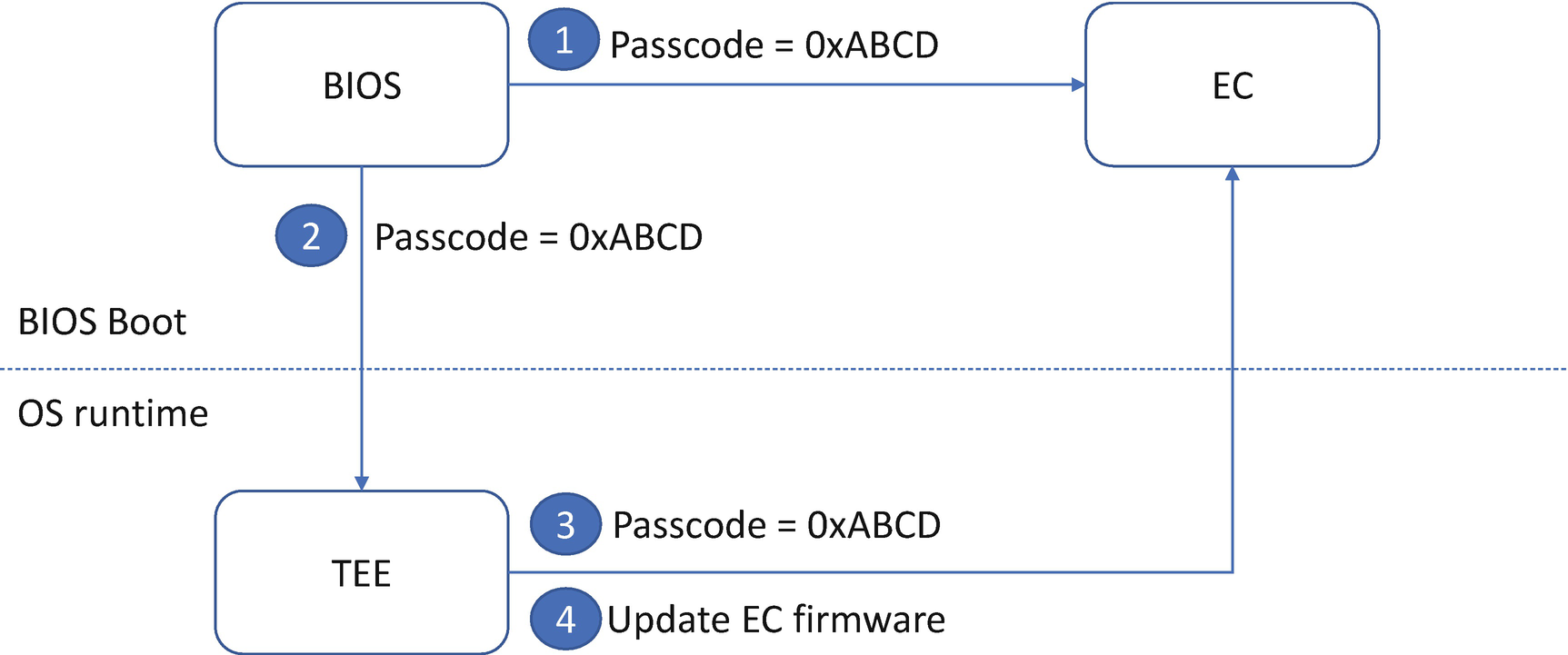
EC Firmware Update with Passcode
Smart Battery Access Code
- 1)
sealed mode: support standard SBS read-only command. This should be default mode when the device is shipped.
- 2)
unsealed mode: support some SBS read/write command. Firmware update should be performed in this mode.
- 3)
full access mode: support all read/write commands. With this mode, the program can enter BootROM and configuration mode. Then the program can tell the battery what level of current, voltage, temp and so on.
In order to prevent malicious access to the device, the smart battery requires an access code to switch the battery mode from sealed mode to unsealed mode, and from unsealed mode to full access mode. Only after the program sends out the right access code can the battery mode can be switched.
Attack & Mitigation
Now, let’s take a look at some real use cases for the attack for the device access control and mitigation.
Default Password or Static Password
If a platform uses the default manufacturer password or a hardcoded static password to unlock the device, the password can be easily retrieved by the attacker if the attacker searches the device data sheet or reverse engineers the firmware code. A platform should always apply the best practices for the device password, such as not hardcoding a password in the firmware, do not use the same manufacturer password for the device, use different passwords for different devices and different platforms.
S3 Resume Attack
The platform BIOS needs to send a TPM2_HierarchyChangeAuth (TPM_RH_PLATFORM) command to take over the TPM2 platform hierarchy in the normal boot to prevent a malicious program from controlling the platform hierarchy. This action should also be considered in the S3 resume because the malicious program may perform the S3 attack against the TPM2 device. If the TPM2 device is suspended successfully, the BIOS uses the TPM2_Startup(State) to resume the TPM2 state. However, if the attack performs the system reset without letting the OS suspend the TPM2 device, the TPM2_Startup(State) will fail in the BIOS S3 resume. A typical BIOS will send TPM2_Startup(CLEAR) to restart the TPM2. Then the platform auth is reset to NULL. In this case, the BIOS must send the TPM2_HierarchyChangeAuth (TPM_RH_PLATFORM) again to initiate a random platform auth value.
Summary
In this chapter, we discussed the access control methods in the firmware, including the boot access control, feature configuration control, device configuration control, storage access control, network access control, device access control. In the next chapter we will discuss the firmware configuration.
References
Conference, Journal, and Paper
[P-1] Jonathan Brossard, “Bypassing Pre-boot Authentication Passwords”, in DEFCON16 2008, available at www.defcon.org/images/defcon-16/dc16-presentations/brossard/defcon-16-brossard-wp.pdf
[P-2] Charlie Miller, “Battery Firmware Hacking”, in BlackHat US 2011, available at https://media.blackhat.com/bh-us-11/Miller/BH_US_11_Miller_Battery_Firmware_Public_Slides.pdf
[P-3] Alex Matrosov, Alexandre Gazet, “Breaking Through Another Side”, in Blackhat US 2019, available at http://i.blackhat.com/USA-19/Thursday/us-19-Matrosov-Breaking-Through-Another-Side-Bypassing-Firmware-Security-Boundaries-From-Embedded-Controller.pdf
[P-4] Jeff Bobzin, “Strategies for Firmware Support of Self-Encrypting Drives”, in UEFI Plugfest 2011, available at https://members.uefi.org/learning_center/UEFI_Plugfest_JBOBZIN_2012Q1_V2.pdf
[P-5] Trusted Computing Group, “TCG Storage Integration Guide”, 2016, available at https://trustedcomputinggroup.org/wp-content/uploads/TCG_Storage_ReferenceDocument_Opal_Integration_Guidelines_v1.00_r1.00.pdf
[P-6] Trusted Computing Group, “TCG TPM v2.0 Provisioning Guidance”, 2017, available at https://trustedcomputinggroup.org/wp-content/uploads/TCG-TPM-v2.0-Provisioning-Guidance-Published-v1r1.pdf
[P-7] sata-io, “Serial ATA Device Sleep (DevSleep) and Runtime D3 (RTD3)”, sata-io whitepaper 2012, available at https://sata-io.org/sites/default/files/documents/SATADevSleep-and-RTD3-WP-037-20120102-2_final.pdf
[P-8] Microsoft, “Encrypted Hard Drive Device Guide”, 2011, available at http://download.microsoft.com/download/8/9/1/891EB055-F1FA-4601-82B4-5FEC784A69EA/encrypted-hard-drive-device-guide.docx
[P-9] Frederick Knight, Sridhar Balasubramanian, “TCG SSC: Key Per IO,” in USENIX Vault ’20, https://www.usenix.org/sites/default/files/conference/protected-files/vault20_slides_balasubramanian_0.pdf
Specification and Guideline
[S-1] NIST SP800-56A, “Recommendation for Pair-Wise Key-Establishment Schemes Using Discrete Logarithm Cryptography”, 2018, available at https://csrc.nist.gov/publications/sp800
[S-2] NIST SP800-56B, “Recommendation for Pair-Wise Key-Establishment Using Integer Factorization Cryptography”, 2019, available at https://csrc.nist.gov/publications/sp800
[S-3] NIST SP800-56C, “Recommendation for Key-Derivation Methods in Key-Establishment Schemes”, 2018, available at https://csrc.nist.gov/publications/sp800
[S-4] NIST SP800-57 Part1, “Recommendation for Key Management, Part 1: General”, 2019, available at https://csrc.nist.gov/publications/sp800
[S-5] NIST SP800-57 Part2, “Recommendation for Key Management: Part 2 – Best Practices for Key Management Organizations”, 2019, available at https://csrc.nist.gov/publications/sp800
[S-6] NIST SP800-57 Part3, “Recommendation for Key Management, Part 3: Application-Specific Key Management Guidance”, 2015, available at https://csrc.nist.gov/publications/sp800
[S-7] NIST SP800-63-3, “Digital Identity Guidelines”, 2017, available at https://csrc.nist.gov/publications/sp800
[S-8] NIST SP800-63A, “Digital Identity Guidelines: Enrollment and Identity Proofing”, 2017, available at https://csrc.nist.gov/publications/sp800
[S-9] NIST SP800-63B, “Digital Identity Guidelines: Authentication and Lifecycle Management”, 2017, available at https://csrc.nist.gov/publications/sp800
[S-10] NIST SP800-63C, “Digital Identity Guidelines: Federation and Assertions”, 2017, available at https://csrc.nist.gov/publications/sp800
[S-11] NIST SP800-90A, “Recommendation for Random Number Generation Using Deterministic Random Bit Generators”, 2015, available at https://csrc.nist.gov/publications/sp800
[S-12] NIST SP800-90B, “Recommendation for the Entropy Sources Used for Random Bit Generation”, 2018, available at https://csrc.nist.gov/publications/sp800
[S-13] NIST SP800-90C, “Recommendation for Random Bit Generator (RBG) Constructions”, 2016, available at https://csrc.nist.gov/publications/sp800
[S-14] NIST SP800-107, “Recommendation for Applications Using Approved Hash Algorithms”, 2012, available at https://csrc.nist.gov/publications/sp800
[S-15] NIST SP800-108, “Recommendation for Key Derivation Using Pseudorandom Functions”, 2009, available at https://csrc.nist.gov/publications/sp800
[S-16] NIST SP800-131A, “Recommendation for Transitioning the Use of Cryptographic Algorithms and Key Lengths”, 2019, available at https://csrc.nist.gov/publications/sp800
[S-17] NIST SP800-132, “Recommendation for Password-Based Key Derivation”, 2010, available at https://csrc.nist.gov/publications/sp800
[S-18] NIST SP800-133, “Recommendation for Cryptographic Key Generation”, 2019, available at https://csrc.nist.gov/publications/sp800
[S-19] NIST SP800-135, “Recommendation for Existing Application-Specific Key Derivation Functions”, 2011, available at https://csrc.nist.gov/publications/sp800
[S-20] FIPS 140-3, “Security Requirements for Cryptographic Modules”, 2019, available at https://csrc.nist.gov/publications/fips
[S-21] Trusted Computing Group, “TCG PC Client Platform Physical Presence Interface Specification”, 2015, available at https://trustedcomputinggroup.org/resource/tcg-physical-presence-interface-specification/
[S-22] Trusted Computing Group, “TCG Storage Architecture Core Specification”, 2015, available at https://trustedcomputinggroup.org/resource/tcg-storage-architecture-core-specification/
[S-23] Trusted Computing Group, “TCG Storage Interface Interactions Specification”, 2018, available at https://trustedcomputinggroup.org/resource/storage-work-group-storage-interface-interactions-specification/
[S-24] Trusted Computing Group, “TCG Storage Work Group Storage Security Subsystem Class: Opal”, 2015, available at https://trustedcomputinggroup.org/resource/storage-work-group-storage-security-subsystem-class-opal/
[S-25] Trusted Computing Group, “TCG Storage Work Group Storage Security Subsystem Class: Opalite”, 2015, available at https://trustedcomputinggroup.org/resource/tcg-storage-security-subsystem-class-opalite/
[S-26] Trusted Computing Group, “TCG Storage Work Group Storage Security Subsystem Class: Pyrite”, 2018, available at https://trustedcomputinggroup.org/resource/tcg-storage-security-subsystem-class-pyrite/
[S-27] Trusted Computing Group, “TCG Storage Work Group Storage Security Subsystem Class: Enterprise”, 2015, available at https://trustedcomputinggroup.org/resource/storage-work-group-storage-security-subsystem-class-enterprise-specification/
[S-28] Trusted Computing Group, “TCG Storage Work Group Storage Security Subsystem Class: Ruby”, 2020, available at https://trustedcomputinggroup.org/resource/tcg-storage-security-subsystem-class-ruby-specification/
[S-29] Trusted Computing Group, “TCG Storage Feature Set: Block SID Authentication”, 2015, available at https://trustedcomputinggroup.org/resource/tcg-storage-feature-set-block-sid-authentication-specification/
[S-30] Trusted Computing Group, “TCG Storage Opal SSC Feature Set: PSID”, 2015, available at https://trustedcomputinggroup.org/resource/tcg-storage-opal-feature-set-psid/
[S-31] Trusted Computing Group, “TCG Storage Opal SSC Feature Set: PSK Secure Messaging”, 2015, available at https://trustedcomputinggroup.org/resource/tcg-storage-opal-ssc-feature-set-psk-secure-messaging/
[S-32] Trusted Computing Group, “TCG Storage Opal SSC Feature Set: Configurable Namespace Locking”, 2019, available at https://trustedcomputinggroup.org/resource/tcg-storage-opal-ssc-feature-set-configurable-namespace-locking/
[S-33] Trusted Computing Group, “TCG Storage Opal SSC Feature Set: Single User Mode”, 2015, available at https://trustedcomputinggroup.org/resource/tcg-storage-opal-ssc-feature-set-single-user-mode/
[S-34] Trusted Computing Group, “TCG Storage Opal SSC Feature Set: Additional DataStore Tables”, 2012, available at https://trustedcomputinggroup.org/resource/tcg-storage-opal-ssc-feature-set-additional-datastore-tables/
[S-35] Trusted Computing Group, “TCG Storage Enterprise SSC Feature Set: Locking LBA Ranges Control Specification”, 2014, available at https://trustedcomputinggroup.org/resource/tcg-storage-opal-ssc-feature-set-additional-datastore-tables/
[S-36] Trusted Computing Group, “TCG Storage Opal Family Feature Set: Shadow MBR for Multiple Namespaces”, 2019, available at https://trustedcomputinggroup.org/wp-content/uploads/TCG_SWG_Feature_Set_ShadowMBR_for_Multiple_Namespaces_v1p00_r1p06_pubrev.pdf
[S-37] IEEE 1667, "Standard Protocol for Authentication in Host Attachments of Transient Storage Devices", 2018, https://standards.ieee.org/standard/1667-2018.html
[S-38] T13 org, “Information technology – ATA Command Set – 4 (ACS-4)”, 2016, www.t13.org/
[S-39] UEFI Organization, “ACPI Specification”, 2019, available at www.uefi.org/
[S-40] PCI-SIG, “PCI Express Base Specification”, 2019, available at https://pcisig.com/specifications
[S-41] IEEE 802.11i, “Wi-Fi Protected Access II”, 2004, available at http://standards.ieee.org/getieee802/download/802.11i-2004.pdf
[S-42] IEEE 802.1X, “Port Based Network Access Control”, 2010, available at http://standards.ieee.org/getieee802/download/802.1X-2010.pdf
[S-43] Bluetooth Org, “Bluetooth Core Specification”, 2019, available at www.bluetooth.com/specifications/bluetooth-core-specification/
[S-44] IETF, “RFC 8446 – The Transport Layer Security (TLS) Protocol Version 1.3”, 2018, available at https://tools.ietf.org/html/rfc8446
[S-45] IETF, “RFC 6347 – Datagram Transport Layer Security Version 1.2”, 2012, available at https://tools.ietf.org/html/rfc6347
[S-46] Trusted Computing Group, “Trusted Platform Module Library”, 2016, available at https://trustedcomputinggroup.org/resource/tpm-library-specification/
[S-47] SBS forum, “Smart Battery Data Specification”, 1998, available at http://sbs-forum.org/specs/
Web
[W-1] “server certificate with invalid domain name (CN) accepted in HTTPS-over-IPv6 boot”, https://bugzilla.tianocore.org/show_bug.cgi?id=960