This chapter describes a critical aspect of platform resiliency – recovery. This supports the availability aspect of the CIA triad of confidentiality, integrity, and availability. If the platform detects that the integrity of components, including code or data, is broken, the platform needs to restore the components to a known good state. This process is called recovery. It is the last element in firmware resiliency. The recovery process is a variant of the update process. It updates the system to an old state. As such, all guidelines for the update should be followed in the recovery process, such as signature checking and version checking.
Image Recovery
The recovery process is performed by the root-of-trust for recovery (RTRec) or the Chain-of-Trust for recovery (CTRec). The RTRec and CTRec shall be the immutable code or the known good code. If the RTRec or CTRec cannot be established, then the end user must perform a manual recovery. For example, if the whole flash chip is corrupt or erased, even the first CPU instruction fetched is an invalid opcode. In this case, the end user might have to attach a flash programmer to the flash chip and burn a new image or be required to ship the machine back to the manufacturer for repair.
RTRec Selection and Recovery Policy
Recovery Policy
Mechanism | RTRec/RTD Relationship | Detail | Example |
|---|---|---|---|
Immediate recovery | The RTRec and RTD are the same. | Once the RTD detects the unauthorized change, the RTD invokes the RTRec, and the RTRec starts doing recovery immediately. | EDK II signed recovery. coreboot recovery. HP Sure Start. Project Cerberus. Intel PFR cold reboot. |
Reset recovery | The RTRec runs before the RTD/CTD. | Once the RTD/CTD detects the unauthorized change, the RTD/CTD sets the platform state to be “recovery mode” and resets the system. On the next boot, the RTRec detects the “recovery mode” and does the recovery. | Intel PFR warm reboot. |
Downgrade boot and late recovery | The RTRec runs after the RTD/CTD. | Once the RTD/CTD detects the unauthorized change, the RTD/CTD continues booting the system with a detectable indicator on the verification failure, such as a TPM measurement. The platform RTRec may have a chance to recover the system to a normal state later. | Intel Boot Guard with the enforcement policy set as timeout shutdown. |
Halt and out-of-band recovery | The RTD and RTRec are in different domains. | Once the RTD/CTD detects the unauthorized change, the RTD/CTD halts the system immediately without any in-band recovery capability. As such, only out-of-band (OOB) RTRec can recover the system. | Intel Boot Guard with the enforcement policy set as immediate shutdown. |
Recovery Image Selection
Recovery Image Selection
Mechanism | Pros | Cons |
|---|---|---|
Immutable ROM | There is no way to break the immutable ROM. | If immutable ROM has a vulnerability, this vulnerability is permanent. |
Last known good image | The platform keeps the recovery image up to date automatically, and the platform ensures there is no known security vulnerability in the recovery image. | It is hard to define what the “good” means. Maybe the platform saves an image which has some functional issue. |
End user saved image | End user has the freedom to decide which image to use for recovery. | End user interaction is required. The end user may select a vulnerable image. |
The solution to automatically save the last known good image poses a challenge because the definition of “good” cannot be precisely defined. Can we say the new image is “good” when the firmware successfully transfers to the OS loader? Or when the OS is fully booted up? Or when the OS device drivers are all started up? Or when the business application starts working in the OS? Or when the OS has passed a certification test? There is no universal answer, and the platform designer needs to make a decision to balance the OS functionality needed to prove the system is in a good state.
Recovery Image Location
Recovery Image Location
Mechanism | Pros | Cons | Example |
|---|---|---|---|
Flash ROM | The recovery image is always present. | The cost is higher. | On the same flash device or a different flash device. |
Non-removable disk | There is no cost increase. | The recovery image itself needs to be protected, and only allow authorized recovery image update. | Hard drive (hard disk drive (HDD) , solid-state disk (SSD), NVMe, and so on) – hidden partition or system partition. |
Removable disk | The recovery image cannot be attacked because it is not attached to the system in a normal boot. | User interaction is required. End user guarantees the correctness of the recovery image. | CDROM/DVDROM, USB key. |
Transmitted from remote | There is no need to touch the local machine. | The network driver stack must be in the RTRec. A recovery server needs to be set up. | Network (Ethernet, Wi-Fi, Bluetooth, and so on), serial port. |
Transmitted via out-of-band (OOB) | It is easy for remote management. | The OOB engine needs to have flash access. | Baseboard Management Controller (BMC), Manageability Engine (ME). |
Case Study
Now, let’s take a look at some real cases for the image recovery.
PCH: Top Swap (TS)
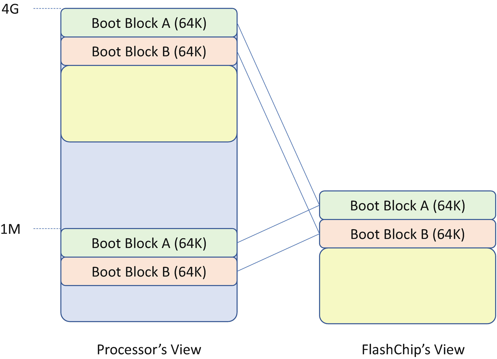
Flash Chip Mapping
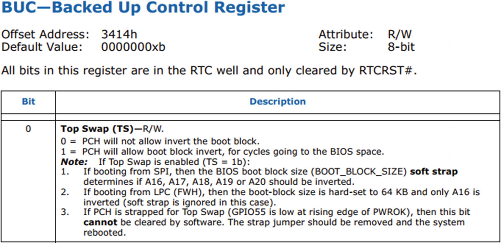
Top Swap Register (Source: Intel 9 Series Chipset PCH Datasheet)
- 1.
The firmware backs up the top block to the block below the top (the swap block).
- 2.
The firmware enables Top Swap. This will invert the appropriate address bits for the cycles going to the Low Pin Count (LPC) or Serial Peripheral Interface (SPI) bus. This bit is stored in the RTC well.
- 3.
The firmware erases the top block and writes the new top block.
- 4.
The firmware disables Top Swap.
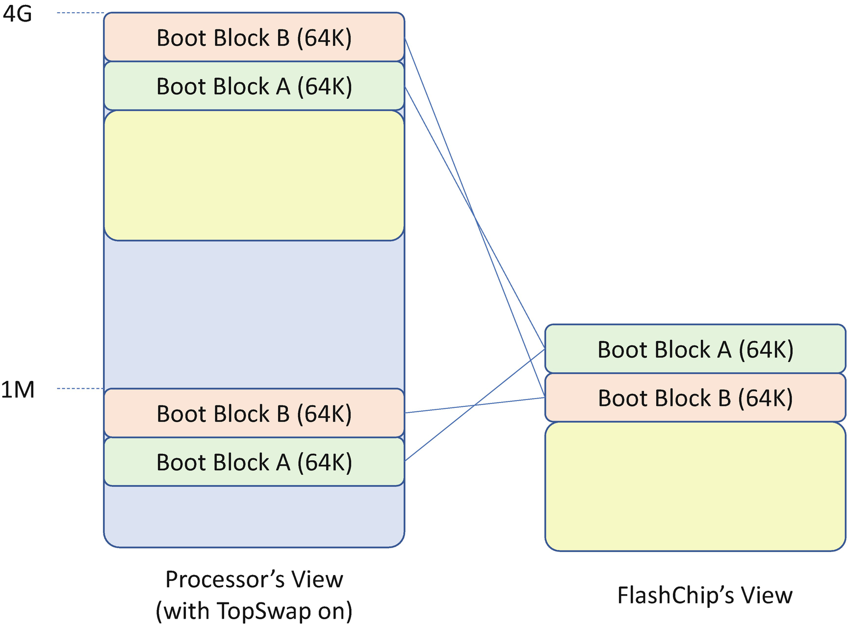
Flash Chip Mapping with Top Swap Enabled
Flash Image Layout to Support Top Swap Recovery
PCH: Boot BIOS Strap (BBS)

Boot BIOS Strap Register (Source: Intel 9 Series Chipset PCH Datasheet)
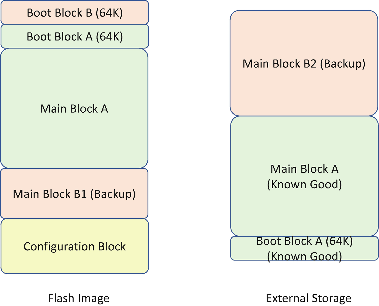
coreboot Recovery

coreboot Recovery Flash Image Layout
EDK II Signed Recovery
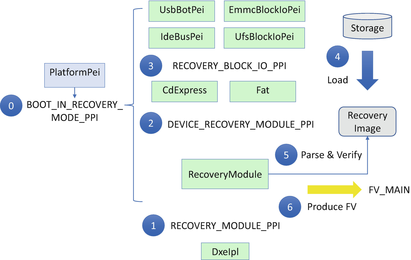
EDK II Signed Recovery Flow
Step 0: During system boot, a platform PEI module detects the boot mode and sets BOOT_IN_RECOVERY_MODE if recovery is required. It also installs the EFI_PEI_BOOT_IN_RECOVERY_MODE_PPI so that modules with the recovery dependency are dispatched in recovery mode.
Step 1: As the final step of the PEI phase, the DxeIpl tries to load the recovery image via EFI_PEI_RECOVERY_MODULE_PPI.LoadRecoveryCapsule if the system boot mode is in BOOT_IN_RECOVERY_MODE.
Step 2: A RecoveryModule is the producer of EFI_PEI_RECOVERY_MODULE_PPI. It consumes EFI_PEI_DEVICE_RECOVERY_MODULE_PPI.
Step 3: The PEI file system driver is the producer of the EFI_PEI_DEVICE_RECOVERY_MODULE_PPI. In EDK II, these modules include CDROM/DVDROM (CdExpressPei) and FAT file system (FatPei). They consume the EFI_PEI_RECOVERY_BLOCK_IO2_PPI.
Step 4: The PEI block I/O storage driver is the producer of EFI_PEI_RECOVERY_BLOCK_IO2_PPI. In EDK II, these modules are USB (UsbBotPei), HDD (IdeBusPei), eMMC (EmmcBlockIoPei), and UFS (UfsBlockIoPei). These PEIMs are the modules to load the recovery capsule image from a storage device into memory.
Step 5: Once the RecoveryModule retrieves the recovery image, it will parse and verify the recovery image to check the integrity and extract the firmware volume for the DXE phase.
Step 6: Finally, the RecoveryModule installs the extracted firmware volume (FV) for DXE. It builds EFI_HOB_FIRMWARE_VOLUME and installs EFI_PEI_FIRMWARE_VOLUME_INFO2_PPI.
Then DxeIpl can find the DXE core and DXE main FV and transfer control to DXE. Later, the DXE phase flash update driver updates the DXE FV in the flash region to finish the recovery.
HP Sure Start
The coreboot recovery and EDK II signed recovery solution assume that the RTD/RTRec and other mutable images are in one single device. It simplifies the board design and lowers the cost. However, in some cases, there is no guarantee that the boot block is really read-only. It can still be updatable. As such, the previous solution does not work.
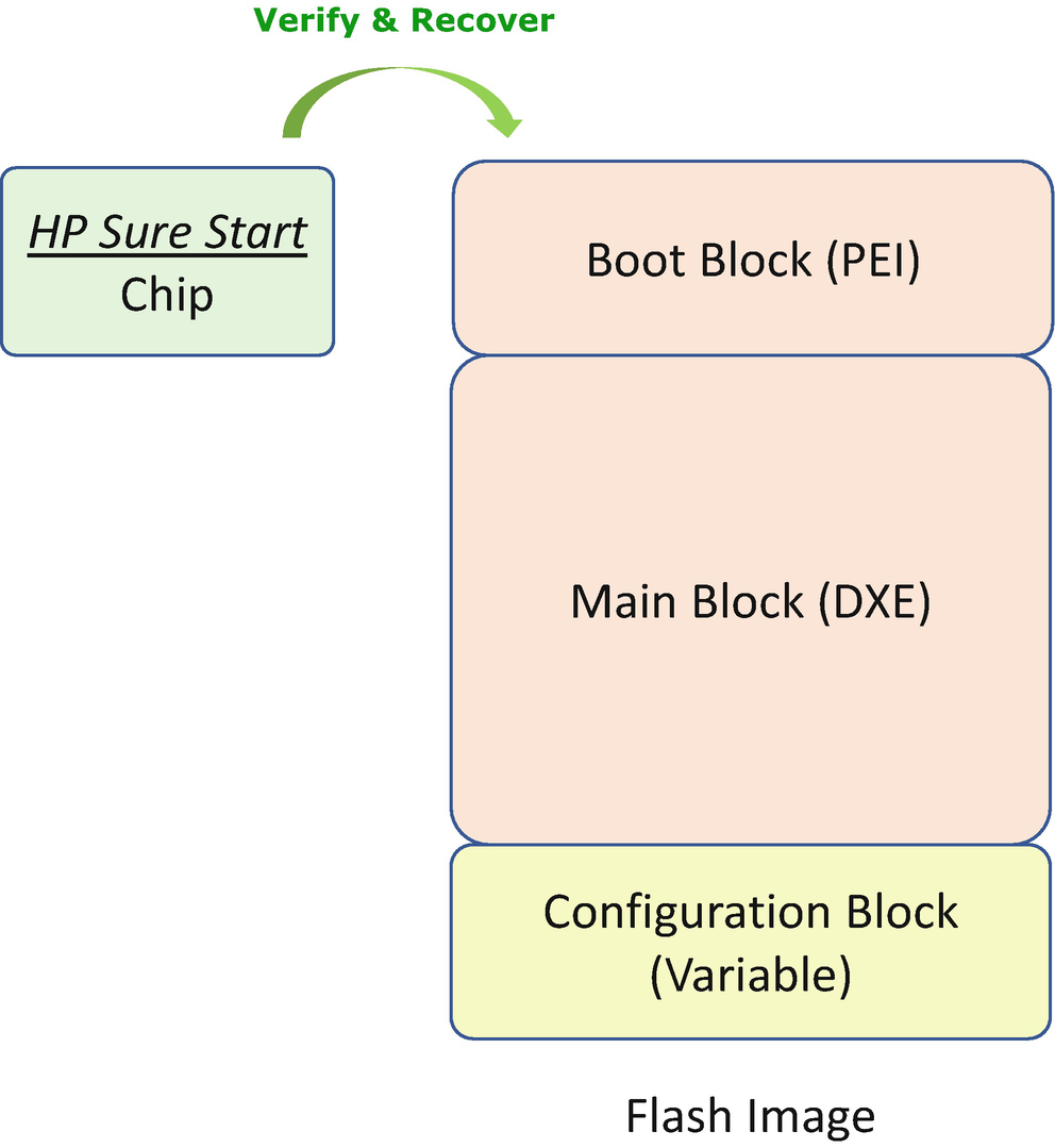
HP Sure Start Detection and Recovery Flow
Project Cerberus
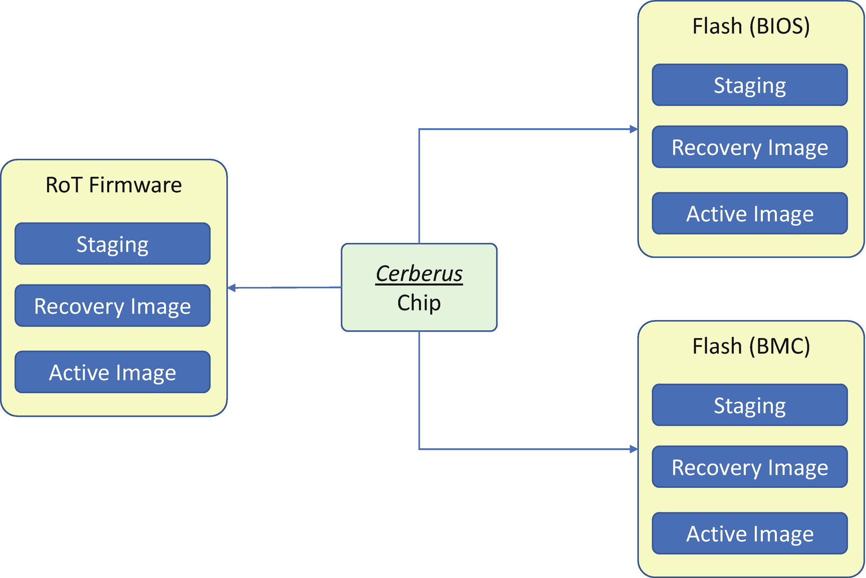
Cerberus Image Layout
Cerberus RoT Command List
Register Name | RoT | Description |
|---|---|---|
Recovery firmware | Platform Active (PA) RoT/Active Component (CA) RoT | Restore Firmware Index using backup. |
Prepare Recovery Firmware | Platform Active (PA) RoT/Active Component (CA) RoT | Prepare storage for recovery image. |
Update Recovery Firmware | Platform Active (PA) RoT | Updates the recovery image. |
Activate Recovery Firmware | Platform Active (PA) RoT | Activates the received recovery image. |
Recovery Configuration Selection
Mechanism | Pros | Cons |
|---|---|---|
Manufacture default | There is no way to break the manufacturer default value, which should be stored in the immutable region or within the recovery image region. | If the manufacturer default value is not a secure configuration, it has to be updated together with the whole recovery image update. |
Last known good configuration | The platform keeps the last configuration data automatically. | Similar to the last known good image, it is hard to define what the “good” means. |
End user saved configuration | End user has freedom to decide which configuration to recover. | End user may save a non-bootable configuration by mistake. |
Besides the BIOS and BMC firmware, the Cerberus root-of-trust (RoT) commands can be used to support device firmware update and recovery image update, once the Cerberus finds the device component firmware has been corrupted.
ARM Trusted Boot Firmware
The recovery implementation in ARM Trusted-Firmware-A is platform specific. A platform may choose to boot to a valid flash image saved in the other position of the flash image, if a recovery boot is required. This action may be combined with a firmware update flow to use the recovery image to overwrite the active image region.

ARM Trusted-Firmware-M Swap Mechanism for Update and Recovery
Attack and Mitigation
Now, let’s take a look at some real cases for the attacks to the image recovery and mitigation of those attacks.
Recovery Image Attack
Since the recovery image is another BIOS image, all hardware attack for the working image may also be applied to the recovery image. If the recovery image is in flash, the flash region must be protected. If the recovery image is on the system partition of the non-removable disk, it is more challenging. This partition must be a protected partition or a hidden partition.
Updating the recovery image is another attack surface. All the rules applied to active image update must be applied to recovery image update too, such as authentication check, version check, non-bypassability, and so on.
Image Downgrade Attack
The recovery image must not have any known security vulnerability. It might be different from the active image and not have the same full functionality as the active image since the major function of the recovery image is to recover the system to a state that can update to a new active image.
When an active image is updated, the platform owner must decide if the vulnerability exists in the recovery image too. If the recovery image has a similar security issue, the recovery image must also be updated along with the active image. Without that, the attack may just trigger the recovery process and activate a vulnerable environment.
Hardware Configuration Attack
The hardware configuration, such as Top Swap (TS) or Boot BIOS Strap (BBS), may help the recovery process. However, the improper usage of this advanced setting may become an attack surface. If those registers are not locked, the attacker can switch the TS or BBS to let the system boot from the other source controlled by the malware. All hardware settings related to security must be locked before the system exits the platform manufacturer authentication phase.
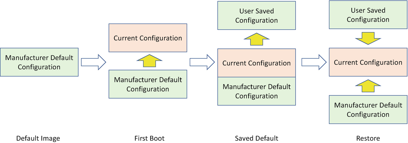
Configuration Recovery
Besides the executable code, the configuration data may also be tampered with or corrupted. If that is detected, the configuration data also needs to perform recovery.
Recovery Configuration Selection
The configuration might be the manufacturer default, a last known good configuration saved by the manufacturer/vendor, or a configuration saved by the end user. If the recovery configuration is mutable, the recovery configuration update must follow the same process as the normal configuration update process. See Table 5-5.
Configuration Recovery
Attack and Mitigation
Now, let’s take a look at some real cases for the attacks to the configuration recovery and mitigation of those attacks.
Configuration Data Attack
Most of the attacks to the recovery configuration are similar to the attacks to the recovery image. The configuration data itself shall be protected.
Configuration Rollback Attack

Configuration Rollback Attack
In order to mitigate such an attack, if a platform needs any configuration update to a secure state, the platform must update the current configuration, the saved configuration, and the default configuration.
Watchdog
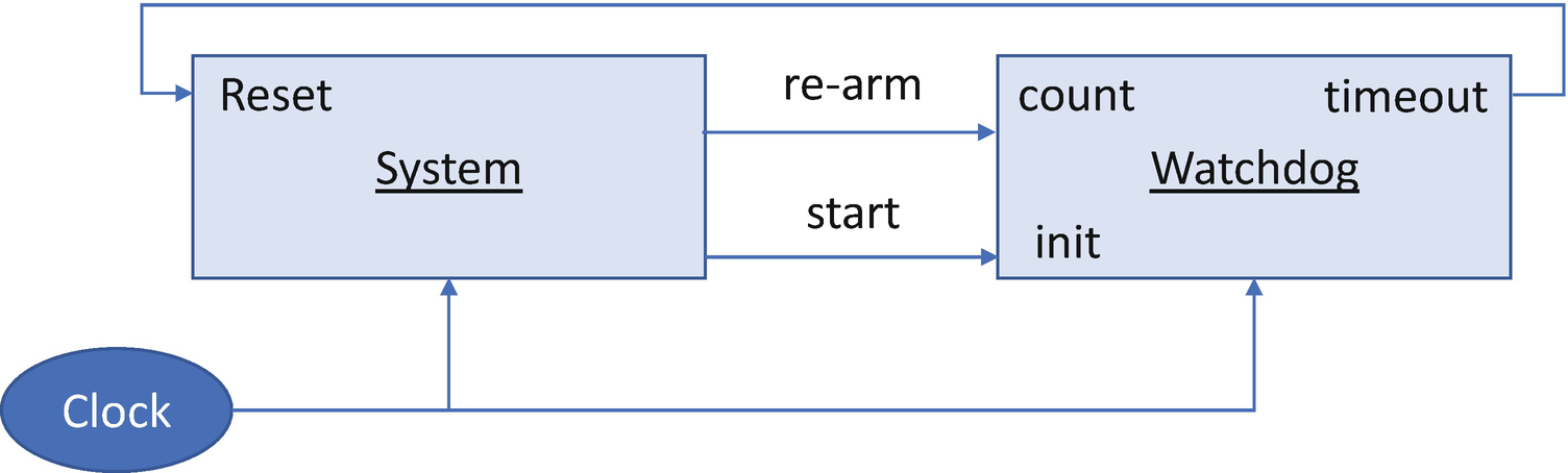
Watchdog
In the resiliency solution, the watchdog should be part of the resiliency engine, such as the platform Root-of-Trust. The watchdog should be started during the platform root-of-trust and should not be stopped or tampered by any exposed vulnerability in the system. In a normal scenario, the system should rearm the watchdog periodically to prevent it from timing out. If the system runs into a corrupted state or hangs, then the system will fail to rearm the watchdog. When the timer elapses, the watchdog will generate a reset signal to initiate the recovery action. This is the firmware equivalent of a “dead man’s switch.”
Currently, the watchdog is widely adopted in computer platforms, such as X86 systems or ARM systems. However, not all of them can be used in the resiliency usage because of the special requirement that the watchdog should be tamper-resistant against a vulnerable resiliency target. A cyber resiliency watchdog should be a latchable watchdog or authenticated watchdog. Only the root-of-trust for resiliency (RTRes) can control it.
Summary
In this chapter, we discussed the third part of the firmware resiliency – recovery. We covered both image recovery and configuration recovery. In the next chapter, we will discuss the OS/loader resiliency.
References
Conference, Journal, and Paper
[P-1] Jiewen Yao, Vincent Zimmer, “A Tour Beyond BIOS- Capsule Update and Recovery in EDK II,” Intel whitepaper, 2016, available at https://github.com/tianocore/tianocore.github.io/wiki/EDK-II-Security-White-Papers
[P-2] Jim Mann, “System Firmware – The Emerging Malware Battlefront,” NIST Computer Security Resource Center, 2015, available at https://csrc.nist.gov/CSRC/media/Presentations/System-Firmware-The-Emerging-Malware-Battlefront/images-media/day1_trusted-computing_100-150.pdf
[P-3] Andrew Thoelke, “ARM Trusted Firmware for ARMv8-A,” Linaro Connect US 2013, available at www.slideshare.net/linaroorg/arm-trusted-firmareforarmv8alcu13
[P-4] Andrew Thoelke, “Adopting ARM Trusted Firmware,” Linaro Connect Asia 2014, available at www.slideshare.net/linaroorg/lca14-102-adoptingarmtrustedfirmware
[P-5] Dan Handley, “ARM Trusted Firmware – from Enterprise to Embedded,” Linaro Connect Las Vegas 2016, available at http://s3.amazonaws.com/connect.linaro.org/las16/Presentations/Thursday/LAS16-402%20-%20Arm-TF%20From%20Embedded%20To%20Enterprise%20v1.0%20%281%29.pdf
[P-6] Dan Handley, Charles Garcia-Tobin, “Trusted Firmware Deep Dive,” available at www.linaro.org/app/resources/Connect%20Events/Trusted_Firmware_Deep_Dive_v1.0_.pdf
[P-7] Sun Bing, “BIOS Boot Hijacking and VMware Vulnerabilities Digging,” in Power Of Community 2007, available at http://powerofcommunity.net/poc2007/sunbing.pdf
[P-8] Alexander Ermolov, “Safeguarding Rootkits: Intel Boot Guard,” in Zeronights 2016, available at https://github.com/flothrone/bootguard/blob/master/Intel%20BootGuard%20final.pdf
[P-9] Alexander Ermolov, “Safeguarding Rootkits: Intel Boot Guard, (part2),” in DC 2017, available at https://github.com/flothrone/bootguard/blob/master/Intel%20BG%20part2.pdf
[P-10] Ronald Aigner, Paul England, Andrey Marochko, Dennis Mattoon, Rob Spiger, Stefan Thom, “Cyber-Resilient Platform Requirements,” Microsoft Whitepaper, 2017, available at www.microsoft.com/en-us/research/publication/cyber-resilient-platform-requirements/
[P-11] Frank Stajano, Ross Anderson, “The Grenade Timer: Fortifying the Watchdog Timer Against Malicious Mobile Code,” in Proceedings of 7th International Workshop on Mobile Multimedia Communications, 2000 available at www.cl.cam.ac.uk/~rja14/Papers/grenade.pdf
Specification and Guideline
[S-1] NIST SP800-193, “Platform Firmware Resiliency Guidelines,” 2018, available at https://csrc.nist.gov/publications/sp800
[S-2] OCP, “Project Cerberus Architecture Overview Specification,” 2018, available at https://github.com/opencomputeproject/Project_Olympus/blob/master/Project_Cerberus
[S-3] OCP, “Project Cerberus Firmware Challenge Specification,” 2019, available at https://github.com/opencomputeproject/Project_Olympus/blob/master/Project_Cerberus
[S-4] OCP, “Project Cerberus Firmware Update Specification,” 2019, available at https://github.com/opencomputeproject/Project_Olympus/blob/master/Project_Cerberus
[S-5] OCP, “Project Cerberus Processor Cryptography Specification,” 2018, available at https://github.com/opencomputeproject/Project_Olympus/blob/master/Project_Cerberus
[S-6] Intel, “Intel® 9 Series Chipset Platform Controller Hub (PCH) Datasheet,” 2015, available at www.intel.com/content/www/us/en/products/docs/chipsets/9-series-chipset-pch-datasheet.html
Web
[W-1] Google, “Firmware Boot and Recovery,” www.chromium.org/chromium-os/chromiumos-design-docs/firmware-boot-and-recovery?tmpl=%2Fsystem%2Fapp%2Ftemplates%2Fprint%2F&showPrintDialog=1
[W-2] Checkm8, https://github.com/axi0mX/ipwndfu