This chapter will provide an overview of system firmware. Although the space of implementations of system firmware is quite broad, details that relate to the secure construction of firmware will be discussed.
Similarity Between Firmware and Software
Firmware vs. Embedded System vs. OS Kernel vs. OS Application
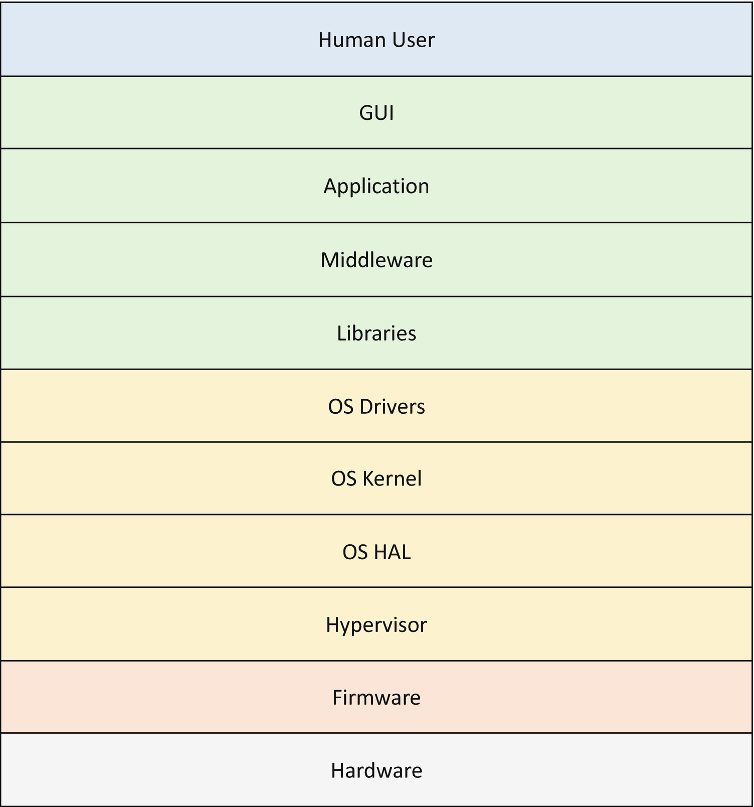
Stack from Hardware to User
Given this C-based provenance, the C code can be susceptible to the class of attacks that afflict higher-level software. These attacks include memory safety issues, involving the variants of buffer overflow, such as stack overflow, heap overflow, and integer overflow. In addition, control flow attacks against C code in the application or OS space can be repurposed against system firmware. Beyond memory issues, other aspects of attack that can occur against the firmware include confidentiality concerns, such as stealing secrets. Beyond that, the firmware often participates in the root-of-trust flow for a system, so integrity considerations are of importance since any unauthorized code flows in the platform can deny the platform promise of that feature. The platform boot can include accessing the network, so considerations of network security can also be applied to the platform firmware. And there are few, if any, platforms that have only a single central processing unit (CPU) core in the system on a chip (SOC), so the firmware must support multiprocessing (MP) and defend against the various classes of attacks, such as race conditions, that inhere in this application domain. Finally, the platform firmware must also defend against other classes of attacks, such as side channels, confused deputy, and time-of-check/time-of-use (TOC/TOU) attacks.
Given these exposure listed, the firmware may have similar platform hardening strategies, albeit with implementations customized for the domain. These include hardening tactics such as stack cookie checks, data execution protection (DEP), address space layout randomization (ASLR), control flow guard/integrity (CFG/CFI), code signing enforcement check, sandbox with interpreter, access control (user authentication and authorization), network security, and cryptography suitable in the firmware execution environment.
Beyond the defenses, the firmware may have similar software security validation strategies, but with different implementations than higher-level software regimes. These validation approaches can include static code analysis, dynamic code analysis (address sanitizer, ASan), fuzzing, symbolic execution, and formal verification when possible.
Distinction Between Firmware and Software
Although firmware is typically written in a higher-level language like C, it often has special requirements. These requirements begin with the environment. Specifically, firmware has a size limitation that is driven by the small ROM size and small RAM size in microcontrollers, only having SRAM or cache that can be used before the DRAM is ready, Management Mode (MM) size leveraging stolen system memory, and limited stack and heap size.
Additional limitations include the execution-in-place (XIP) code of early code. Namely, some code executes in the ROM. One aspect of this is the ROM code, wherein some code has no writable global variable in the data section. And for this early code, such as the UEFI Platform Initialization PI, Slim Bootloader stage 1, and coreboot romstage, there is no memory management, including no virtual memory, although page tables may be used.
Beyond memory management, there are challenges with execution isolation in early code flows. For example, ring separation might or might not be available. As such, some firmware implementations just run all code in supervisor mode. And although the hardware may contain multiple CPU cores, multiprocessing (MP) may or may not be enabling. In fact, most implementations of host firmware execute services on a single processor. Alongside MP, other common capabilities like interrupts may be enabled, but only for usages much simpler than those of operating systems. And unlike the OS, the firmware usually interacts directly with the hardware. Finally, the firmware will have its own executive infrastructure, such as a kernel and loader, distinct from those found in high-level operating systems (HLOSs) like Windows or Linux or hypervisors.
Given these limitations, firmware may have a class of security issues about which we are to be concerned that are not seen in HLOSs. These security concerns can include attack from the hardware, such as registers, device Direct Memory Accesses (DMAs), cache, and so on. Beyond those threat vectors, the host firmware must guard against a permanent denial of service (PDoS) in the ROM which often necessitates complicated and special recovery mechanisms. And if the PDoS concern were not enough, firmware can be susceptible to a permanent root kit in the body of the ROM that is difficult to discover by virus scanning art.
Introduction to Firmware Security

Three Pillars of Firmware Security
Firmware Resiliency

Three Axes of Firmware Resiliency Capabilities
Firmware Measurement and Attestation
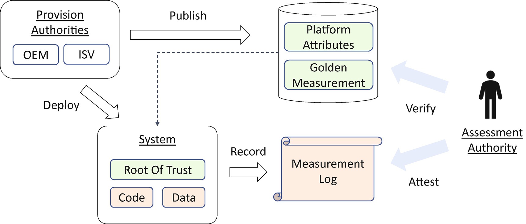
Firmware Measurement and Attestation
Secure Device Communication
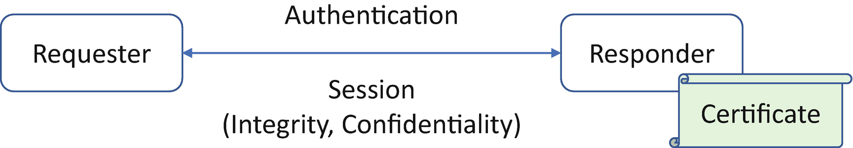
Secure Device Communication
Introduction to Variants of Host Firmware
Host firmware includes firmware running on the main or “host” CPU, as distinct from non-host firmware that runs in the SOC or device firmware that may run in a peripheral. The host firmware has many responsibilities for the platform, including two primary roles: initialize the hardware and launch the next stage of the system. The former task of initializing the hardware spans setting up the state of the central processing units (CPUs), initializing the Dynamic Random Access Memory (DRAM), and enumerating the I/O buses. The latter role of host firmware can include accessing the local block storage or network to download the operating system. Both of these phases have respective threat models and dependencies on the hardware.

System Block Diagram
Industry Standards
Of the industry standards, there are several. Some are intended to have interoperability with the I/O devices, such as the Universal Serial Bus (USB) and Peripheral Component Interconnect (PCI). These allow for having more consistent system software that programs against a hardware interface, as distinct from having unique device drivers to abstract the capabilities of every interface. Beyond these device-to-host hardware interfaces, though, there are also standards between the host firmware and the operating system. These include the Advanced Configuration and Power Interface (ACPI) for detailing non-enumerable aspects of the platform and a set of runtime-interpreted tables for both configuring and managing the platform state at runtime. Another important standard is the System Management BIOS (SMBIOS) standard which provides static tables detailing the inventory of the platform. Finally, for purposes of abstracting the platform block, network, and console devices from the operating system loader, there is the Unified Extensible Firmware Interface (UEFI). UEFI complements other standards like ACPI and SMBIOS by providing a well-known mechanism to discover the content, but it goes further. Specifically, UEFI provides a rich set of capabilities and interfaces for discovering executable content, or “.efi” files, in PCI adapter card option ROMs (OROMs) and on storage devices. This allows for decoupling the manufacturer of the platform, such as the Original Equipment Manufacturer (OEM) and the operating system vendor (OSV).
Boot Flow and Phased Handoff
There are various means of restarting the system. These include a cold restart such as an S5, a CPU-only reset such as warm start, a memory-preserving restart such as an S3, or a hibernation-based restart such as ACPI S4.
In general, firmware has at least three phases, including providing a root-of-trust, turning on the SOC and the system’s main memory, initializing the platform, and booting the operating system.
There are typically some minimal firmware requirements, such as providing some root-of-trust for measurement, verification, and update. This ensures that the firmware can report the state of the firmware environment while booting and only update itself with some platform manufacturer-approved content.
Typically, the boot of a platform is decomposed into three phases. The first includes turning on the basic system on a chip complex, including system DRAM. This is also where the core root-of-trust for measurement (CRTM) and the static update and verification root-of-trust can commence. This early phase is represented in various firmware architectures, such as the UEFI PI Security (SEC) and Pre-EFI Initialization (PEI), coreboot boot block and romstage, Slim Bootloader stage 1, Open Power self-boot engine (SBE) and hostboot, and U-Boot First Stage Boot Loader (FSBL). Ideally this phase will be predominately SOC-specific code with little vendor code. An example of SOC-only vendor code would be a SOC boot ROM, and a mixed board and SOC code solution can include the Intel Firmware Support Package (FSP).
The next phase of execution can include richer software abstractions since the firmware is guaranteed to have initialized system memory that will maintain its configuration throughout the life of the platform. As such, the UEFI PI Driver Execution Environment (DXE), U-Boot Secondary Program Loader (SPL) , Open Power skiboot, Slim Bootloader stage 2, and coreboot RAM stage can have richer algorithmic flows. This stage typically hosts the setup application for a PC class system, creation of ACPI and SMBIOS tables, and programming of other board-specific capabilities. This phase, unlike the prior one, is less SOC code specific and more system board and product specific. This phase of execution must continue the root-of-trust logic for measurement, update, and verification, though, and the code should be provisioned under the authority of the platform manufacturer. This phase is typically the latest point during which the runtime phase of the platform can be provisioned, including but not limited to allocating memory for management mode, such as X86 system management mode (SMM) RAM (SMRAM), data spaces for the runtime-accessible ACPI and SMBIOS tables, and, finally, data and code spaces for the UEFI runtime services.
Following the board-specific initialization, the persona for operating booting is entered. This persona can include the UEFI-conformant execution environment which allows for third-party extensible executables from disk, PCI host bus adapters, and network. The Boot Device Selection (BDS) is the traditional point at which policy actions around these third-party codes begin and the phase of execution referred to as the Transient System Load (TSL). For the coreboot and Slim Bootloader, this phase of execution is characterized by the launching of a payload. The payload can contain a UEFI-style environment, such as EDK II DXE, or it can contain a Linux-based boot environment such as LinuxBoot. The payloads are typically considered part of the firmware Trusted Computing Base (TCB), in addition to the former two phases.
The predominant role of this last phase of firmware execution is to discover and potentially abstract services for the next phase of execution, or HLOS runtime. As such, upon exiting this phase of execution, the pre-OS phases should quiesce most of the hardware and prepare for the HLOS to take over. In the case of a UEFI system, the end of the TSL is the invocation of ExitBootServices by the OS loader or OS kernel.
Once the HLOS has taken over from the payload and/or UEFI boot service environment, the host firmware plays much less of a role. In fact, the OS kernel or hypervisor will have its own driver stack to manage the state of the processors, SOC, and I/O devices. The host firmware will be largely passive with only limited callbacks into firmware via synchronous invocations from the OS, such as the UEFI runtime services, synchronous traps into management mode via hardware mailbox access from agents outside of the Trusted Execution Environment (TEE), or asynchronous invocation into the TEE via TEE-specific timer sources or side effects of other SOC-specific hardware activations. The integrity of the runtime TEE, such as Management Mode, is still part of the host firmware TCB and should only be services by manufacturer-approved updates.

Phased Firmware Initialization
Introduction to Non-host Firmware
The host firmware, such as EDK II or coreboot, are not the only firmware entities on the platform. Other firmware that are typically under the control of the platform manufacturer include the Baseboard Management Controller (BMC) on servers and Embedded Controllers (ECs) on client platforms. These devices typically interact with the host firmware during the early phases of execution and may in fact run prior to the host firmware since they can provide a root-of-trust for the host firmware or sequence the power capabilities of the platform.
These non-host firmware elements should be recorded by the host firmware root-of-trust for measurement, if possible, and these non-host elements may have their root-of-trust for update (RTU) and verification proxied through the host. In either case, these elements are part of the platform manufacturer’s TCB typically and should not be exposed to arbitrary third-party updates.
The OpenBMC project and the Chrome EC are examples of open source non-host platforms available in the market. Given the inclusion in the manufacturer’s TCB, following the security practices for firmware development is key for having a robust product.
Introduction to Device Firmware
Beyond the manufacturer’s host firmware (sometimes known as BIOS) and non-host platforms (EC, BMC, and so on), the PCI card, USB devices, and other components such as Complex Programmable Logic Device (CPLD), Field Programmable Gate Array (FPGA) or Digital Signal Processing (DSP) on the system board may have their own firmware. In fact, a review of a modern client platform noted sixteen different firmware elements, and a server example quoted a multiple of that figure.
There are some examples of device firmware, such as Open Sound Firmware, for programmable audio devices, but in general the device firmware is opaque to and independent of the host firmware. As such, there are protocols to query these devices for their state and add them to security policy so that the host firmware can provide a holistic view of the platform state to the HLOS.
And given that the device firmware reads in on the platform security posture, construction of this firmware, just like the other non-host firmware devices, is imperative for having a robust platform experience.
Summary
This chapter has described the various aspects of host firmware, including its role in the platform. Given that contemporary firmware is written predominately in C, various classes of security considerations that impact higher-level application software are described. In the next chapter, we will discuss the proactive firmware security development.
References
Book
[B-1] Jiming Sun, Vincent Zimmer, Marc Jones, Stefan Reinauer, Embedded Firmware Solutions, 2015, Apress
[B-2] Vincent Zimmer, Michael Rothman, Suresh Marisetty, Beyond BIOS: Developing with the Unified Extensible Firmware Interface, 3rd edition, 2017, DeG
[B-3] Vincent Zimmer, Michael Rothman, Robert Hale, UEFI: From Reset Vector to Operating System, in Chapter 3 of Hardware-Dependent Software, Springer, 2009
[B-4] Sunil Cheruvu, Anil Kumar, Ned Smith, David M. Wheeler, Demystifying Internet of Things Security, 2020, Apress
Conference, Journal, and Paper
[P-1] David Weston, “Hardening With Hardware,” in BlueHat 2018 https://github.com/microsoft/MSRC-Security-Research/blob/master/presentations/2018_01_BlueHatIL/BlueHatIL18_Weston_Hardening_With_Hardware.pdf
[P-2] David Weston, “Advanced Windows Security,” in Platform Security Summit 2019, www.platformsecuritysummit.com/2019/speaker/weston/
[P-3] Eclypsium, “Anatomy of a Firmware Attack,” 2019, https://eclypsium.com/2019/12/20/anatomy-of-a-firmware-attack/
[P-4] Eclypsium, “FISMA compliance firmware security best practices,” 2019, https://eclypsium.com/2019/05/13/fisma-compliance-firmware-security-best-practices/
[P-5] NIST, “Hardware-Enabled Security for Server Platforms,” in NIST whitepaper, 2020, available at https://nvlpubs.nist.gov/nistpubs/CSWP/NIST.CSWP.04282020-draft.pdf
Specification and Guideline
[S-1] UEFI Organization, “UEFI Specification,” 2019, available at www.uefi.org/
[S-2] UEFI Organization, “UEFI Platform Initialization Specification,” 2019, available at www.uefi.org/
[S-3] UEFI Organization, “ACPI Specification,” 2019, available at www.uefi.org/
[S-4] PCI-SIG, “PCI Express Base Specification,” 2019, https://pcisig.com/
[S-5] CXL Org, “Compute Express Link Specification,” 2019, www.computeexpresslink.org/
Web
[W-1] EDK II, www.tianocore.org/
[W-2] coreboot, www.coreboot.org/
[W-3] Linux Boot, www.linuxboot.org
[W-4] Slim Bootloader, https://slimbootloader.github.io/
[W-5] U-Boot, www.denx.de/wiki/U-Boot
[W-6] Intel Firmware Support Package (FSP), www.intel.com/FSP
[W-7] Sound Open Firmware (SOF), https://github.com/thesofproject
[W-8] Open Baseboard Management Controller (openbmc), https://github.com/openbmc/openbmc
[W-9] Open Power, https://github.com/open-power