After we finish all of the code development work, we need to perform security testing. Usually, the developers need to perform security unit testing and then deliver the code to the test team. At this point, the test team needs to perform more thorough system-level security testing. There are many books that introduce software testing techniques. We will not repeat those contents here. Instead, in this chapter, we will focus on the firmware-specific security unit testing from a developer’s perspective. In the next chapter, we will focus on the firmware-specific system security testing from a test engineer’s perspective.
Security Unit Testing Plan
Security Unit Test for Eight High-Risk Areas
Category | Security Unit Test |
|---|---|
External input | Identify the external input – SMM communication buffer, UEFI variable, firmware image and capsule image, boot BMP file, PE/COFF image such as an OS bootloader and PCI option ROM, file system, disk image, network packet, and so on. Identify the function to handle the external input – boundary function.Identify the function to perform the check for the external input – check function. Test the check function with different input. Verify the output of the check function. |
Race condition | Identify the critical resource – SMM communication buffer, locked silicon registers, and so on. Identify the function to handle the critical resource.Create a race condition scenario to access the critical resources. Verify the result of the critical resource. |
Hardware input | Identify the hardware inputs – read/write silicon register, memory mapped input/output (MMIO) base address register (BAR), USB descriptor, Bluetooth Low Energy (BLE) advertisement data, DMA, cache, and so on. Identify the function to handle the hardware input. Identify the function to perform the check for the hardware input – check function – or identify the function to prevent the attack, lock function. Emulate the hardware input such as MMIO BAR, USB, BLE, and so on; and test the check function. Verify the output of the check function. Verify the lock function to perform the lock correctly, such as DMA or SMM cache and so on. |
Secret handling | Identify the secret/password. Identify the function to use the secret. Identify the function to clear the secret after use. Ensure the secret is cleared in all paths. Identify the function to hash or encrypt the secret if the secret needs to be saved. Identify the default secret/password handling. Verify that the side channel guidelines are followed. |
Register lock | Identify the registers to be locked, such as flash lock and SMM lock. Identify the function to lock the register. Identify the policy to control the lock, such as a policy protocol or variable. Ensure the end user cannot control the policy. Ensure the lock happens in all boot paths. Ensure the lock happens before any third-party code runs. |
Secure configuration | Identify the policy to control the security configuration, such as secure boot and measured boot. Ensure that the unauthorized end user cannot update the secure configuration.Ensure the default configuration is secure. |
Replay/rollback | Identify the secure version number (SVN) or lowest supported version number (LSN). Identify the storage for the SVN or LSN. Ensure the unauthorized end user cannot update the SVN or LSN.Identify the function to perform the version check. |
Cryptography | Identify the cryptographic usages in the firmware, such as signature verification or data encryption. Identify the cryptographic algorithm used in the firmware. Ensure that the cryptographic algorithm follows the latest guidelines from the government and corporations. Do not use any deprecated algorithm. Ensure the key length follows the latest guidelines from the government and corporations. Do not use small lengths. Identify the key provision function and the key revocation function. Identify the key storage. Identify the function to protect the key storage for integrity and/or confidentiality. Only authorized users can update the key. Verify if the side channel guideline is followed for the confidentiality of the key. Ensure the signature verification function can handle cases for a missing key or signature. |
Care must be taken for solutions that may involve multiple high-risk areas. Taking SMM-based firmware update as an example, the firmware update image is an external input (#1). The image is put into an SMM communication buffer which may have a potential Time-of-Check/Time-of-Use attack (#2). The flash update function needs to unlock the flash, which leaves open the possibility of a race condition attack (#2). The SMM environment should be protected to prevent a DMA or SMM cache attack (#3). The flash device should be locked during boot to prevent any unauthorized updates (#5). The firmware update function should check the SVN of the firmware to prevent a rollback attack (#7). The new firmware image must be signed with a proper cryptographic algorithm with proper length key (#8).
In order to verify if the developed code follows the general secure coding practices, which we introduced in Chapter 14, static code analysis or dynamic code analysis can be used. In Chapter 16, we introduced the different compiler defensive technologies to eliminate potential vulnerabilities, including Klocwork and Coverity static analysis tools, and we also described the address sanitizer and Undefined Behavior Sanitizer.
Advanced Security Unit Testing
In general, for security unit testing, we may need to write a test function to call the target function with different input in order to assess if the target function works properly, especially to test the target function’s ability to handle both external input (#1) and hardware input (#3). One of the biggest problems with this approach is that we don’t know if we have created enough input to cover all cases.
Traditionally, equivalence class partitioning (ECP) is a good approach to remove the redundancy by dividing the input data into a reasonable number of partitions. Then we only need to design test cases to cover all partitions. However, although ECP is necessary, it is not sufficient for the security unit testing because the perquisite of ECP is that we are able to define a set of partitions that cover all cases. This is true for simple functions, but in practice, it might be hard to define a complete set of ECP partitions for a complicated data structure, such as a file system, an executable file format, or a network packet. Therefore, we need some other approach.
Fuzzing
- 1)
Crash, hang, or ASSERT is a simple and objective measurement for fuzzing. If those behaviors are observed, then there must be something wrong in the target function.
- 2)
Fuzzing might also trigger some other hard-to-detect problems, such as a buffer out of bound access, use-after-free, or memory leak. In order to catch those failures, fuzzing is usually enabled together with other sanitizers, such as address sanitizer, undefined behavior sanitizer, memory sanitizer, or leak sanitizer.
- 3)
Last but not least, fuzzing may cause the program to return unexpected or wrong results. As such, the developer may need to write assertions for the final result or the final state of the program.
Fuzzing is a testing technique. It is independent of the execution environment. It can be applied to OS applications, OS kernels, or even firmware. Today, most of the fuzzing tools, such as Peach, American Fuzzy Lop (AFL), and LibFuzzer, run in the OS environment. But firmware runs in a special execution environment, and this environment does not provide the same OS-level application program interface (API) or standard C library. This begs the question: How do we run the fuzzing tool to test the firmware code?
Firmware Fuzzing Mechanisms
Mechanism | Effort | Pros | Cons |
|---|---|---|---|
1. Run firmware function and fuzzing tool in the firmware environment. | Port the fuzzing tool to run in the firmware. | No need to modify the firmware code. | Big effort to port a fuzzing tool. May have environment limitations, such as memory size, storage size, and CPU processing power. |
2. Run firmware function in the firmware environment and fuzz tool in the OS. | a. Create a firmware agent and an OS agent for fuzzing data transmission between firmware and OS via the network. | No need to modify the fuzzing tool. No need to modify the firmware code. | Time-consuming in fuzzing data transmission. |
b. Use a hypervisor for data communication between the firmware function and OS fuzzing tool. | Faster than fuzzing data transmission via network. | Need to enable a hypervisor to run the target firmware. | |
3. Run the firmware function and fuzzing tool in the OS environment. | a. Port the firmware function to the OS and perform fuzzing of it in the OS. | No need to modify the fuzzing tool. Can fully leverage the instrumented code with the fuzzing compiler. Fastest solution. | Needs effort to create an OS stub for the firmware function. |
b. Analyze the firmware binary and perform fuzzing of the target function. | No porting of the firmware is needed. | Binary analysis is time-consuming. Needs to create a stub function as well. |
- 1)
The first option is to port the fuzzing tool from the OS to the firmware environment and run it in the firmware environment. See Figure 21-1. If the fuzzing tool depends upon an OS API, we need to implement a firmware version. Unfortunately, the porting effort is large, based upon our analysis. It also means that continuous porting is required if we need to keep the fuzzing tool up to date. At the same time, we have seen different fuzzing tools created to deal with different scenarios. It is hard to port all of those tools. Even if we can port all of the fuzzing tools, it still might be hard to run the tool because of the limitations of the firmware execution environment, such as ROM size, SRAM size, DRAM size, storage size, and CPU processing power. The fuzzing tool may fail to run or run at a very slow speed.

Firmware Fuzzing with Fuzz Tool Running in Firmware
- 2)
The second option is to create an agent in the firmware and let the firmware agent accept the fuzzing data from the OS. An OS fuzzing agent invokes the fuzzing tool to generate the fuzzing data and transfers the data from the OS to the firmware agent. See Figure 21-2. However, we might run into performance problems because some time is wasted in the communication between the OS and UEFI. Fuzzing usually requires a large amount of data generation and usually needs to run for several days. If the time is wasted in the data communication, then the fuzzing is not efficient.
One possible variant is to enable a hypervisor to run both the target firmware and the OS fuzzing tool on one local machine. It might be faster than communication via the network, but we need to pursue a porting effort in order to let the hypervisor run the firmware.
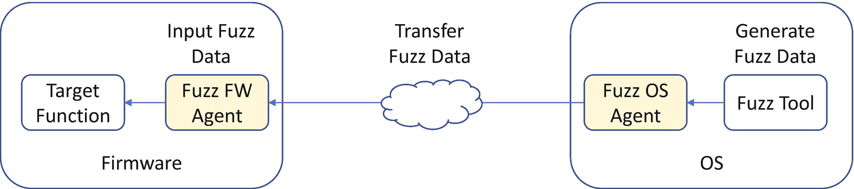
Firmware Fuzzing with Fuzz Agent Communication
- 3)
The third option is to make the firmware target function run in the OS environment and use the OS fuzzing tool directly. Because the firmware function may rely on the firmware-specific services which might not be available in the OS, we need to create the OS stub function to provide this service. If this can be achieved, we can reuse the OS fuzzing tool directly. See Figure 21-3. The advantage of this approach is that we can fully leverage the capability of an OS fuzzing tool, such as instrumented mode, and the host system resources, including memory size, disk storage. and the host CPU execution power. This is the fastest solution.
One possible variant of this option is that we may fuzz a specific firmware function in a binary in cases where we don’t have the source code. Herein, we must carefully analyze the firmware binary and provide all dependent services. The advantage of this approach is that we can fuzz any firmware binary without having the source code, but we lose the benefit of instrumented fuzzing, and it is much slower than with the source code.
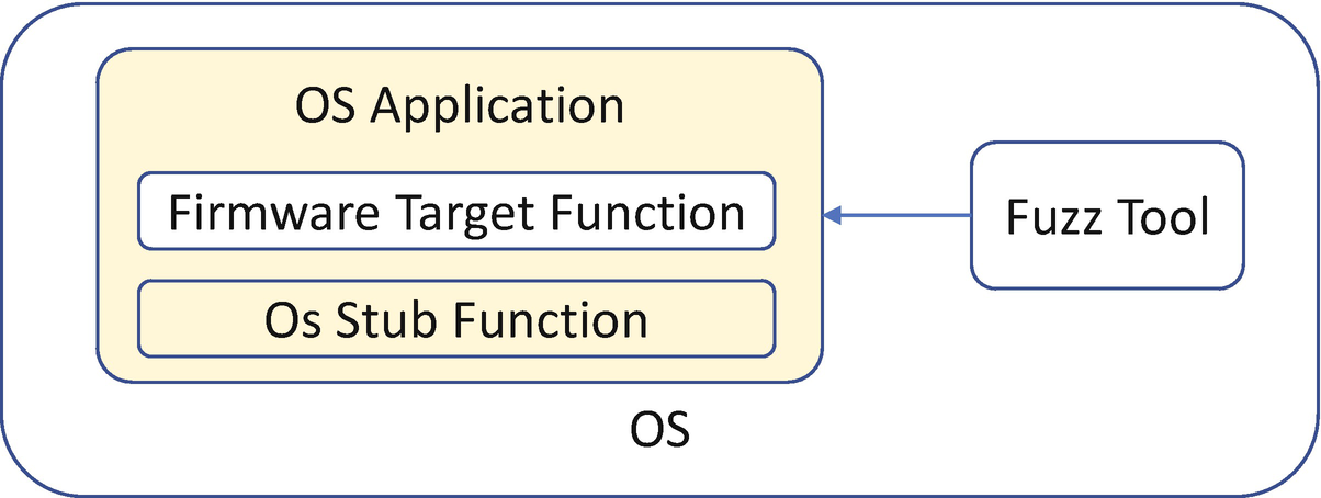
Firmware Fuzzing with Firmware Code Running in OS
HBFA Fuzz Case Design
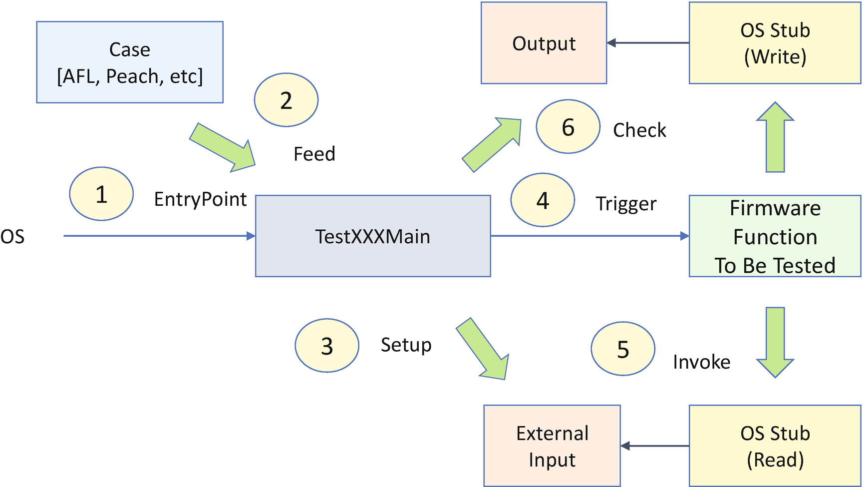
Step 1: We run the test application with the OS fuzzing tool.
Step 2: The fuzzing tool generates fuzz data and feeds it to the test main function as an input parameter.
Step 3: The test main function sets up the external input data for the firmware function based upon the fuzzing data.
Step 4: The test main function triggers the firmware function to be tested.
Step 5: The firmware function calls the OS stub function to get the external input. Here the external input can be a communication buffer, a signed firmware capsule image, a PE/COFF executable image, a boot image file, a file system, a network packet, a USB descriptor, a Bluetooth LE advertisement data, and so on. Then the firmware function may call the OS stub to write some output data.
Step 6: The test main function can check the output data based upon the test oracle. At the same time, we can enable the sanitizer for the test application to see if there is any violation at runtime.
Symbolic Execution
Some fuzzing tools require known good seeds for mutation, and the fuzz data is generated based upon the seeds. Even if the seeds are optional, the good seeds can help improve the efficiency of the fuzzing. There are several ways to get seeds. Seeds can be ascertained via an empty seed, downloading seeds from the Internet, using the existing system configuration as the seeds, and using a tool to generate the seeds. The last one can be achieved by a symbolic execution tool, such as KLEE.
During a normal execution session, the program reads a concrete input value and proceeds with the execution flow, such as assignment, addition, multiplication, and conditional branch until generating a concrete final answer. However, during a symbolic execution, the program reads a symbolic value and proceeds with the execution flow. It can still do assignment, addition, and multiplication, though. When it reaches a conditional branch, the symbolic execution can proceed with both branches by forking down two paths. Each path gets a copy of the program state to continue executing independently in a symbolic fashion with a path constraint. The path constraint here means the concrete value which makes the program choose a specific path in the branch condition. When a path is terminated, the symbolic execution computes a concrete value by solving the accumulated path constraints on the branch condition. After all paths are terminated, the symbolic execution collects all concrete values. Those values can be thought of as test cases to cover all of the possible paths for the given program.
Listing 21-1.

AFL Fuzz + KLEE
Symbolic execution is a good method to generate the seed. However, it has limitations. Because symbolic execution needs to fork the state based on each branch condition, the number of states to be maintained grows exponentially with the increase in the program size. For a complex program, it may take a long time to generate the final result for all paths. In some cases, it might run into infinite loops or generate an exception.
Formal Verification
Formal verification is a technology to prove the correctness of code in a system with respect to certain specifications or predefined properties by using formal method of mathematics. The approach of the formal verification is model checking, which is a systematically exhaustive exploration of the mathematical model. Symbolic execution is one implementation method that can be used in the formal verification. Spin is an open-source software verification tool, used for the formal verification of multi-threaded software applications. C bounded model checker (CBMC) is a bounded model checker for C and C++ programs which verifies memory safety (which includes array bounds checks and checks for the safe use of pointers), checks for exceptions, checks for various variants of undefined behavior, and user-specified assertions.
===========================
There are not many software projects passing formal verification, because of the complexity of the software programs. Writing a complete set of program properties is also challenging work. Some operating systems have been verified, such as secure embedded L4 kernel (seL4). Some network stacks are also verified, such as verified HTTPS in project Everest.
Design for Security Test
- 1)
We begin by writing small functions and testing the small functions. A small function is easy for code review and testing. For example, in the EDK II UEFI variable driver MdeModulePkg/Universal/Variable/RuntimeDxe/Variable.c, the UpdateVariable() routine has 600 lines of code and 65 “if” branches. One of the “if” branches misses the “else” branch handling and causes the timestamp field to be filled with a wrong value. This issue had been there for several years. We performed several rounds of code reviews and testing, but no one found this problem. Sixty-five “if” branches in one function is overly complicated.
- 2)
Next, consider combining all input data verifications into one check function and testing the check function itself. Some programs have multiple functions to accept the external input. We refer to those functions as boundary functions. We notice that the boundary function may perform some sanity checks against the external input and subsequently pass control to the business logic function for data processing. See Figure 21-6. A potential risk of this approach is that each boundary function does the check in its own function. If there is one security issue exposed in one boundary function, we have to review all other boundary functions to see if there is a similar issue. Unfortunately, that is time-consuming and people may make mistakes. For example, the first Microsoft ANI bug issue (CVSS 9.3 HIGH, MS05-002) was found in 2005. But after the fix, the same issue (MS07-017) was found in 2007. They shared the same root cause, and it coincidentally happened in two different functions.
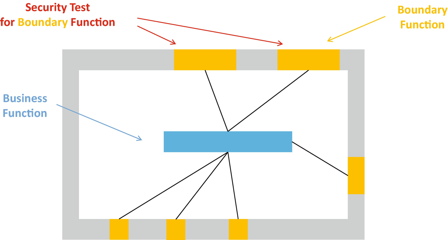
Test for the Security Boundary Function

Test for the Security Checker Function
- 3)
Next, let all external boundary functions call the check function and test the execution flow. It is good to define a centralized check function. We need to ensure that all boundary functions invoke the same check function before transferring control to the business logic function by having a security test for the execution flow.
Summary
In this chapter, we introduced the security unit test. The chapter covered the security unit test plan for the eight high-risk areas in the firmware – external input, race conditions, hardware input, secret handling, register locks, secure configuration, replay/rollback, and cryptography. Then we introduced two advanced security unit test methods – fuzzing and symbolic execution – and we provided a suggestion for the check function. In the next chapter, we will introduce the security validation and penetration test methodology for the firmware.
References
Book
[B-1] Brian Chess, Jacob West Secure, Programming with Static Analysis, Addison-Wesley Professional, 2007
[B-2] Michael Sutton, Adam Greene, Pedram Amini, Fuzzing: Brute Force Vulnerability Discovery, Addison-Wesley Professional, 2007
[B-3] James A. Whittaker, Hugh Thompson, How to Break Software Security, Addison-Wesley Professional, 2003
Conference, Journal, and Paper
[P-1] John Neystadt, “Automated Penetration Testing with White-Box Fuzzing,” Microsoft, 2008, available at https://docs.microsoft.com/en-us/previous-versions/software-testing/cc162782(v=msdn.10)
[P-2] Yuriy Bulygin, Oleksandr Bazhaniuk, “Discovering vulnerable UEFI BIOS firmware at scale,” in 44CON 2017, available at https://github.com/abazhaniuk/Publications/blob/master/2017/44CON_2017/Bulygin_Bazhaniuk_44con.pdf
[P-3] Sugumar Govindarajan, John Loucaides, “The Whole is Greater,” in NIST CSRC 2015, https://csrc.nist.gov/CSRC/media/Presentations/The-Whole-is-Greater/images-media/day1_trusted-computing_200-250.pdf
[P-4] Brian Richardson, Chris Wu, Jiewen Yao, Vincent J. Zimmer, “Using HBFA to Improve Platform Resiliency,” Intel White paper, 2019, https://software.intel.com/sites/default/files/managed/6a/4c/Intel_UsingHBFAtoImprovePlatformResiliency.pdf
[P-5] Marek Zmysłowski, “Feeding the Fuzzers with KLEE,” in KLEE workshop 2018, available at https://srg.doc.ic.ac.uk/klee18/talks/Zmyslowski-Feeding-the-Fuzzers-with-KLEE.pdf
[P-6] Oleksandr Bazhaniuk, John Loucaides, Lee Rosenbaum, Mark R. Tuttle, Vincent Zimmer, “Symbolic execution for BIOS security,” in USENIX WOOT 2015, available at www.markrtuttle.com/data/papers/bazhaniuk-loucaides-rosenbaum-tuttle-zimmer-woot15.pdf
[P-7] Zhenkun Yang, Yuriy Viktorov, Jin Yang, Jiewen Yao, Vincent Zimmer, “UEFI Firmware Fuzzing with Simics Virtual Platform,” in DAC 2020, available at http://web.cecs.pdx.edu/~zhenkun/pub/uefi-fuzzing-dac20.pdf
[P-8] Christopher Domas, “God Mode Unlocked Hardware Backdoors in X86 CPUs,” in BlackHat 2018, available at http://i.blackhat.com/us-18/Thu-August-9/us-18-Domas-God-Mode-Unlocked-Hardware-Backdoors-In-x86-CPUs.pdf
[P-9] Byron Cook, Kareem Khazem, Daniel Kroening, Serdar Tasiran, Michael Tautschnig, Mark R. Tuttle, “Model checking boot code from AWS data centers,” Formal Methods in System Design, 2020, https://link.springer.com/content/pdf/10.1007/s10703-020-00344-2.pdf
Web
[W-1] Using HBFA to Improve Platform Resiliency,
[W-2] HBFA, https://github.com/tianocore/edk2-staging/tree/HBFA
[W-3] libfuzzer, https://llvm.org/docs/LibFuzzer.html
[W-4] Peach fuzzer, http://community.peachfuzzer.com/v3/Test.html
[W-5] AFL fuzzer, http://lcamtuf.coredump.cx/afl/
[W-6] KLEE, https://klee.github.io/
[W-7] STP, http://stp.github.io/
[W-8] Z3, https://github.com/z3prover/z3
[W-9] metaSMT, https://www.informatik.uni-bremen.de/agra/eng/metasmt.php
[W-10] mini SAT, http://minisat.se/
[W-11] Verifying Multi-threaded Software with Spin, http://spinroot.com/spin/whatispin.html
[W-12] Bounded Model Checking for Software, https://www.cprover.org/cbmc/
[W-13] Low-Level Bounded Model Checker (LLBMC), http://llbmc.org/
[W-14] Symbiotic, https://github.com/staticafi/symbiotic
[W-15] seL4, https://sel4.systems/
[W-16] Project Everest, www.microsoft.com/en-us/research/project/project-everest-verified-secure-implementations-https-ecosystem/, https://project-everest.github.io/
[W-17] Microsoft Security Bulletin MS05-002, available at https://docs.microsoft.com/en-us/security-updates/securitybulletins/2005/ms05-002
[W-18] Microsoft Security Bulletin MS07-017, available at https://docs.microsoft.com/en-us/security-updates/securitybulletins/2007/ms07-017