This chapter covers the following Cisco-specific objectives for the “Describe the operation of data networks” section of the 640-822 ICND1 exam:
<objective>Use the OSI and TCP/IP models and their associated protocols to explain how data flows in a network
</objective> <objective>Describe common networked applications including web applications
</objective> <objective>Describe the purpose and basic operation of the protocols in the OSI and TCP models
</objective> <objective>Determine the path between two hosts across a network
</objective> </feature><feature><title>Outline</title>10 | |||
10 | |||
11 | |||
11 | |||
12 | |||
12 | |||
13 | |||
14 | |||
14 | |||
15 | |||
15 | |||
17 | |||
18 | |||
18 | |||
18 | |||
20 | |||
21 | |||
21 | |||
22 | |||
23 | |||
23 | |||
25 | |||
26 | |||
27 | |||
27 | |||
30 | |||
31 | |||
31 | |||
32 | |||
33 | |||
33 | |||
33 | |||
34 | |||
35 | |||
35 | |||
37 | |||
37 | |||
40 | |||
40 | |||
41 | |||
41 | |||
45 | |||
47 | |||
49 | |||
Read through the exam objectives at the beginning of the chapter.
Review the characteristics of each internetwork and keep in mind which network would be appropriate based on a given company and its individual requirements.
Identify the names and primary functions of each OSI model layer. Create a mnemonic device to help you remember the seven layers.
Identify the protocols and standards that are used at each layer of the OSI model. Pay close attention to the application protocols used at the Application layer.
Review and memorize associated UDP and TCP port assignments for several well-known protocols.
Whether you already work in the computer technology industry, or you are trying to enter the field as a newcomer, it is important in this day and age to back up your resume with a vendor-specific certification. If you search job postings on the Internet, it is commonplace for hiring companies today to require or recommend that an applicant have at least one vendor certification. Other companies ask that their current employees obtain certifications as a way to meet goals for advancement. Regardless of the underlying reason, studying for the CCENT is a smart move.
The CCENT certification was developed by Cisco to test your knowledge of networking at a beginner’s level. Cisco wants to identify individuals capable of installing, configuring, and maintaining small-scale networks, which include Local Area Networks (LANs) and Wide Area Networks (WANs).
The purpose of this first chapter is to provide a general overview of the concepts that will ultimately be the foundation for the rest of this book. To start this chapter, the first step is to define the term internetwork. It then reviews the general concepts that pertain to LAN and WAN internetworks, as well as the Metropolitan Area Network (MAN), Storage Area Network (SAN), and Virtual Private Network (VPN). Later chapters go into more detail regarding the technologies that are related to both LAN and WAN.
This chapter also gives an in-depth look at the three networking reference models that are likely to be tested on the CCENT exam. These are the Open Systems Interconnection (OSI), Transmission Control Protocol/Internet Protocol (TCP/IP), and Cisco 3-Layer Hierarchical models. Being familiar with these models is fundamental to understanding how networks operate, as well as how various devices and protocols fit into their structure. By using these models, you can design an infrastructure based on a given organization’s specific requirements.
Simply put, an internetwork is the connection of more than one network. These networks are linked together by an internetworking device to provide communication between the networks. Internetworks may also be referred to as an internet. Notice the lowercase i at the beginning of the word internet—this differentiates it from the Internet. The Internet is considered to be the largest internet in the world. I know the phrase sounds odd, but it is a great example of how thousands of smaller networks are joined together to form one large global internetwork. Another example of an internet would be the connection of individual LANs to form a WAN.
The term internetworking signifies the industry, products, and processes that are required to handle the challenges of network interoperability. Such issues can be quite complex because of the existence of multiple vendors and protocols.
There are various types of internetworks discussed in greater detail. I already mentioned LAN and WANs, which are the most common types of internetworks. Other important internetworks include MANs, SANs, and VPNs, which are also reviewed in this section.
Like the name suggests, LANs are limited to a local or small geographical area. An example of a LAN would be a network of individual computers or workstations that are connected in a single department. These users have shared access to resources such as data and network devices. Users on a LAN segment can share a network printer and communicate with one another via email. Also, they are governed by one authoritative administrator.
Note
LAN is the smallest network in geographical size.
Given the size constraints, downsides of a LAN network are limited distance that data can travel and a limited number of computers that can be connected. An upside of a LAN is fast data transfer with data speed that can reach up to 10Gbps.
Xerox Corporation worked in collaboration with DEC and Intel to create ethernet, which is the most pervasive LAN architecture used today. Ethernet has evolved and has seen significant improvements in regard to speed and efficiency.
Other significant LAN technologies are Fiber Distributed Data Interface (FDDI) and token ring.
Exam Alert
An understanding of LAN technology is required for the CCENT exam. Each ethernet version is discussed in detail in Chapter 3, “Data Link Networking Concepts.”
Local area networking uses switches, bridges and/or repeaters, and hubs to interconnect LANs and increase overall size. Routers are used to connect a LAN to a WAN or MAN. Both of these scenarios form an internetwork.
Figure 1.1 provides an example of a LAN. A single switch connects to all the peripheral network devices in this example.

A MAN is larger than a LAN but smaller than or equal in size to a WAN. Think of it as the size of a city or college campus network, which can range anywhere from 5 to 50km in diameter. MANs are typically owned and managed by a single entity. This could be an ISP or telecommunications company that sells its services to end-users in that metropolitan area. For all intents and purposes, a MAN has the same characteristics as a WAN with distance constraints.
WANs cover more than one geographical area. This is ideal for a company that has offices in different cities around the country or even the world. Each office can connect to the other sites in the WAN via a router. Connectivity from router to router is a circuit leased from a telephone or communications company, such as AT&T to name one. The larger the circuit a company needs to transmit data, the more it costs to lease. The company also needs to pay close attention to the performance of its WAN connection because that cost can directly impact its ability to do business. It is important to keep an eye on the amount of traffic that is going over each circuit to ensure that you have sufficient throughput. Throughput refers to the amount of data transferred in a specified timeframe.
Note
Earlier I mentioned that the Internet is the perfect example of an internetwork. It is also an excellent example of a WAN network where thousands of small networks are joined together to form one large global network.
The following are WAN encapsulations that are reviewed in Chapter 17, “Wide Area Network Connections”:
Frame Relay
PPP
HDLC—Cisco standard
Exam Alert
WAN characteristics, protocols, services, and troubleshooting techniques are all possible exam topics. Therefore, WAN technologies are discussed in length in Chapter 17.
Figure 1.2 provides an example of a WAN. In this example, a central router connects two LANs to create the WAN. Each LAN has a switch connected to its local end-user devices.

SAN may be referred to as a subnetwork or special purpose network. Its special purpose is to allow users on a larger network to connect various data storage devices with clusters of data servers. Cisco offers this service with its Cisco MDS 9000 Series Multilayer SAN Switches. These switches provide scalable storage solutions for the end user.
VPN is a private network that can access public networks remotely. VPN uses encryption and security protocols to retain privacy while it accesses outside resources. When employed on a network, VPN enables an end user to create a virtual tunnel to a remote location. Typically, telecommuters use VPN to log in to their company networks from home.
Objectives:
Use the OSI and TCP/IP models and their associated protocols to explain how data flows in a network
Describe common networked applications including web applications
Describe the purpose and basic operation of the protocols in the OSI and TCP models
By now you understand the concept of an internetwork. Now the OSI model will help you see just how an internetwork operates by using a layered architecture.
The International Organization for Standardization (ISO) created the OSI model as the first major attempt to internetwork various vendor-specific networks, the ultimate goal being that these different vendor networks could work together in harmony. This model consists of seven layers. Although it is not widely used today, the terminology is prevalent in the networking community. The OSI model may also be helpful when troubleshooting a network issue.
First of all, it is important to know the name of each layer and its corresponding layer number. This will help you remember where the layers reside in the OSI model. You may also hear the layers referred to by number, so knowing them will also help in that respect. Table 1.1 provides a list of all seven layers.
In general, each layer communicates with the adjacent layers on the OSI model and the corresponding layer on another system. For example, the Presentation layer communicates with the Application layer, the Session layer, and also with the Presentation layer of another connected system.
Exam Alert
It is crucial that you learn the layers of the OSI model and their respective functions. Also know that the OSI model helps with multi-vendor integration. The functions are reviewed in this chapter. For now, to help you remember the names of the layers and their order, it may be helpful to come up with a mnemonic device. The most commonly used phrase is “All People Seem To Need Data Processing.” There are many other phrases out there, some of which are quite crass, but it is ultimately up to you to decide whether this will help.
Now that you know the layers in order, it is also important to know that the layers may also be referred to as the upper and lower layers. Primarily, the upper layers of the OSI model define communications between applications that reside on end-user stations. This is generally related to software communication. Table 1.2 provides a list of the layers considered as the upper layers.
Layer 7 provides an interface between a host’s communication software and any necessary external applications (such as email, file transfers, and terminal emulation). This layer can also evaluate what resources are necessary to communicate between two devices and determine their availability.
Layer 7 also provides the following functionality:
Synchronization of client/server applications
Error control and data integrity between applications
System-independent processes to a host
Table 1.3 provides a list of the protocols supported by the Application layer.
Table 1.3. Application Protocols Supported by the Application Layer
Application Protocols | Function |
|---|---|
A TCP/IP protocol that provides terminal emulation to a remote host by creating a virtual terminal. Secure CRT is one program that can be installed on a user computer to create telnet sessions. This protocol requires authentication via a username and password. | |
Hypertext Transfer Protocol (HTTP) | Enables web browsing with the transmission of Hypertext Markup Language (HTML) documents on the Internet. |
Secure Hypertext Transfer Protocol (HTTPS) | Enables secure web browsing. A secure connection is indicated when the URL begins with https:// or when there is a lock symbol at the lower-right corner of the web page that is being viewed. |
File Transfer Protocol (FTP) | Enables a user to transfer files. Provides access to files and directories. Securely implemented with telnet, which allows remote authentication to an FTP server. |
Trivial File Transfer Protocol (TFTP) | A bare-bones version of FTP that does not provide access to directories. With TFTP, you can just send and receive files. Unlike FTP, TFTP is not secure and sends smaller blocks of data. |
Domain Name System (DNS) | Resolves hostnames such as www.cisco.com into IP addresses. |
Simple Mail Transfer Protocol (SMTP) | Sends electronic mail across the network. |
Post Office Protocol 3 (POP3) | Receives electronic mail by accessing an Internet server. |
Network File System (NFS) | Enables users with different operating systems (for example, NT and Unix workstations) to share files. |
Network News Transfer Protocol (NNTP) | Offers access to Usenet newsgroup postings. |
Simple Network Management Protocol (SNMP) | Monitors the network and manages configurations. Collects statistics to analyze network performance and ensure network security. |
Network Time Protocol (NTP) | Synchronizes clocks on the Internet to provide accurate local time on the user system. |
Dynamic Host Configuration Protocol (DHCP) | Works dynamically to provide an IP address, subnet mask, domain name, and a default gateway for routers. Works with DNS and WINS (used for NetBIOS addressing). |
Layer 6 presents data to the Application layer and acts as a data format translator. Format translation is necessary to ensure that the data can be read by applications. Layer 6 also handles the structuring of data and negotiating data transfer syntax to Layer 7. Processes involved include data encryption, decryption, compression, and decompression.
Layer 6 protocols include the following:
Joint Photographic Experts Group (JPEG)
American Standard Code for Information Interchange (ASCII)
Extended Binary Coded Decimal Interchange Code (EBCDIC)
Tagged Image File Format (TIFF)
Graphic Image File (GIF)
Picture (PICT)
Moving Picture Experts Group (MPEG)
Musical Instrument Digital Interface (MIDI)
QuickTime
Rich Text Format (RTF)
Layer 5 is primarily concerned with dialog control among devices. This layer determines the beginning, middle, and end of a session or conversation that occurs between applications. In this way, the Session layer acts as an intermediary for those applications. Table 1.4 lists the Session layer protocols and their functionality.
Table 1.4. Session Layer Protocols and Their General Functionality
Session Layer Protocol | Function |
|---|---|
Network File System (NFS) | Accesses remote resources transparently and represents files and directories as if local to the user system. Developed by SUN and used on Unix workstations. |
Structured Query Language (SQL) | Functions as a query language that requests, updates, and manages databases. Developed by IBM and compatible with XML and HTML. |
Remote Procedure Call (RPC) | Basis for client/server communications. Calls are created on the client and then carried out on the server. |
AppleTalk Session Protocol (ASP) | Also client/server–based communications, but specific to AppleTalk client and server devices. |
Communicates with remote Unix machines and enables the user to operate the device as if attached locally. | |
Digital Network Architecture Session Control Protocol (DNA SCP) | A proprietary Digital Equipment Corporation Networking (DECnet) protocol, also referred to as a DECnet session. |
The lower layers of the OSI model focus on data transport, which can be achieved via a router, switch, or a physical wire. They are listed in Table 1.5.
Layer 4 is responsible for end-to-end connections and data delivery between two hosts. The ability to segment and reassemble data is a key functionality of this layer. For example, when one system is sending data to another system, that data can be segmented into smaller data blocks and transmitted across the network. The receiving system can then reassemble the segmented data blocks at the Transport layer. Transmissions occur via logical connectivity between the sender and destination. Layer 4 provides transparent data transfer by hiding details of the transmission from the upper layers.
Layer 4 also provides the following functionality:
Fault detection
Error recovery
Establishing, maintaining, and tearing down virtual circuits
The Transport layer can provide reliable networking via acknowledgments, sequencing, and flow control.
Acknowledgments—. Delivered segments are acknowledged to the sender. If they are not acknowledged, the sender will retransmit.
Sequencing—. Data segments are sequenced into their original order when they arrive at the destination.
Flow Control—. Provides buffer controls that prevent packet flooding to the destination host. Buffers store bursts of data for processing when the transmission is complete.
Layer 4 protocols include the following:
Transmission Control Protocol (TCP)
User Datagram Protocol (UDP)
Sequenced Packet Exchange (SPX)—A reliable communications protocol created by Novell NetWare
Note
TCP and UDP protocols are important to know for the exam. These are discussed later in this chapter, under the “Transport Layer” section of the TCP/IP model.
Layer 3 is where the best path determination is made for packet delivery across the network. Routed protocols such as IP are used to determine logical addressing, which can identify the destination of a packet or datagram. The most common network device found at the Network layer is a router; however, Layer 3 switches may also be implemented.
A router at the Network layer follows these general steps to ensure proper data transport:
The router checks the destination IP address of the incoming packet on the router interface.
Packets destined for that router are processed, whereas packets destined for another router must be looked up in the routing table.
The router determines an exit interface based on the routing table and sends the packet to the interface for framing and forwarding. If there is no route in the routing table, the packet is dropped by the router.
A routing table on a router contains the following information:
Network Address
Interface—Exit interface used to forward packets
Metric—Distance to reach a remote network
There are two packet types utilized at Layer 3:
Data Packets—. Transport data across the internetwork and are supported by IP and IPX protocols.
Route Update Packets—. Send updates to neighbor routers about all networks connected to that internetwork and are supported by routing protocols such as RIP, EIGRP, and OSPF.
Layer 3 routed protocols include the following:
Internet Protocol (IP)
Internet Packet Exchange (IPX)—Part of the IPX/SPX protocol suite created by Novell NetWare
AppleTalk DDP—Datagram delivery protocol used by Apple
Exam Alert
For the exam, this book focuses on IP, which is reviewed in Chapter 5, Implementing IP Addressing.
Layer 2 ensures reliable data transfer from the Network layer to the Physical layer for transmission across the network.
Two domains determine data transport reliability:
Broadcast Domain—. A group of nodes that can receive each other’s broadcast messages and are segmented by routers.
Collision Domain—. A group of nodes that share the same media and are segmented by switches. A collision occurs if two nodes attempt a simultaneous transmission. Carrier Sense Multiple Access Collision Detection (CSMA/CD) is an access method that sends a jam signal to notify the devices that there has been a collision. The devices then halt transmission for a random back-off time.
Data received from the Network layer is formatted into frames to be transmitted to the Physical layer. Physical addressing or hardware addressing (rather than logical addressing) ensures that data is delivered to the appropriate node on the LAN. This layer is also responsible for error notification (not correction), network topology, and flow control.
This is the only layer of the OSI model that has sublayers. The two sublayers in question define the IEEE Ethernet 802.3 frame, which in turn provides physical addressing and flow control. Also, routed protocol information (IP, IPX, AppleTalk, and so on) is provided to the upper layers.
The IEEE Ethernet 802.3 sublayers are Media Access Control (MAC) and Logical Link Control (LLC), and are described in the following sections.
The MAC address is the hard-coded address on the network interface controller (NIC) of the Physical layer node attached to the network. Although the source address will always be a unicast or single destination address, the destination address can be a unicast, multicast (a determined subset of nodes), or broadcast (all nodes in a broadcast domain) address.
Each MAC address must be unique and follow this format:
This is an example of a MAC address: 00:00:07:A9:B2:EB
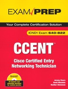
The LLC sublayer complements the MAC sublayer in the ethernet model; the LLC is responsible for framing, error, and flow control. LLC provides a service access point (SAP) identifier in the frame. The SAP field of the frame consists of one byte that identifies an upper layer protocol (for example, 06 = IP, whereas E0 = IPX). The LLC inserts a destination SAP (DSAP) and a Source SAP (SSAP) in the frame. Figure 1.3 provides an example of an ethernet frame.
Two devices are used at the Data Link layer:
Bridges—. Bridges connect two segments in a single network or two networks together. They simply forward data between those segments/networks without performing an analysis or redirection of the data.
Switches—. At Layer 2, switches are multi-port bridges that utilize Application Specific Integrated Circuit (ASIC) to forward frames. Each port of the switch has a dedicated bandwidth.
Exam Alert
Dedicated bandwidth enables the switch port to guarantee the speed assigned to that port. For example, 100Mbps port connections get 100Mbps transmission rates.
Although both devices create a separate collision domain for each connected device, all the devices connected to either are a part of the same broadcast domain. Remember that broadcast domains are segmented at the Network layer by routers.
Switches and bridges identify MAC addresses by scanning for the source MAC address of each frame received.
Note
Bridging and switching are discussed in more detail in Chapter 3.
Layer 1 moves bits between nodes. Electrical, mechanical, procedural, and functional requirements are defined at the Physical layer to assist with the activation, maintenance, and deactivation of physical connectivity between devices.
Other attributes of Layer 1 include the following:
Note
Although DTE is the locally attached device, DCE is typically found at the service provider. DTE services can be accessed with either a model or a channel service unit/data service unit (CSU/DSU). For additional information on associated Layer 1 technologies, continue on to Chapter 2, “Physical Layer Networking Concepts.”
Devices at the Physical layer include hubs and repeaters. Hubs and repeaters extend a network, whereas Layer 2 and Layer 3 devices segment a network.
Now that you have reviewed all seven layers of the OSI model, it is a good time to see how those layers communicate with each other. Each layer passes information to adjacent layers by using Protocol Data Units (PDUs). The PDU includes both the message and the protocol/control information from the forwarding layer. That control information can be in the form of a header or trailer. The process of adding a header or trailer to the PDU at each layer of the OSI is called encapsulation.
Each layer has an associated control information name, which is listed in Table 1.6.
Based on this chart, you can see how information is encapsulated as it travels down through the various layers. The correct order for data encapsulation is data, segment, packet, frame, and bit.
Objectives:
Use the OSI and TCP/IP models and their associated protocols to explain how data flows in a network
Describe common networked applications including web applications
Describe the purpose and basic operation of the protocols in the OSI and TCP models
Determine the path between two hosts across a network
The TCP/IP model, also known as the Department of Defense (DoD) model, was created by the DoD when they developed the TCP/IP protocol suite. Their goal was to provide reliable networking and data integrity in the event of a disaster. This model is prevalent in the current networking community. Although the OSI model is rarely used (except for the terminology), TCP/IP communications are ingrained in today’s networking fabric and are a focal point on the CCENT exam.
Note
So far, the Internet has been a great example of an internetwork and a WAN. It’s also a great example of the TCP/IP protocol suite at work.
Essentially the TCP/IP model has many similarities to the OSI model. Table 1.8 lists the layers of the OSI model in the left column and the related layers of the TCP/IP model in the right.
This layer combines functionalities of the three top layers of the OSI model and may also be called the Process/Application layer. Also, some of the most popular applications (email, file transport, and so on) interface with this layer to communicate with other applications on the network.
If you’ll remember, the description of the Application layer of the OSI model included a list of application protocols and their primary functions. (Refer to Table 1.3.) These applications are also relative to the Application layer of the TCP/IP model.
Table 1.9 provides a quick list of the protocols at their respective layers of the TCP/IP model.
The Transport layer corresponds with the Transport layer of the OSI model and is also known as the Host-to-Host layer. Not only is this layer responsible for reliable data delivery, but it can also make certain that data arrives in the proper order. You will see two transport layer protocols on the CCENT exam. These protocols are TCP and UDP. The following sections cover each protocol and its related applications.
TCP is a reliable connection-oriented protocol. TCP uses acknowledgments, sequencing, and flow control to ensure reliability (please refer back to the “Transport Layer” section of the OSI model for definitions of these terms). A TCP segment contains fields for the Sequence, Acknowledgment, and Windowing numbers. These fields help make sure that datagrams arrive undamaged. This is considered to be reliable delivery.
TCP uses Positive Acknowledgment and Retransmission (PAR):
The source device begins a timer when a segment is sent and retransmits if the timer runs out before an acknowledgment is received.
The source device keeps track of segments that are sent and requires an acknowledgment for each segment.
The destination device acknowledges when a segment is received by sending a packet to the source that iterates the next sequence number it is looking for from the source.
Figure 1.4 shows the TCP segment header format.
Flow control via TCP includes windowing. Windowing is a method for traffic congestion control where a window is determined by the receiving system to limit the number of data segments (bytes) that can be sent by the source device without an acknowledgment from the recipient. The size of a window determines the number of unacknowledged data segments allowed by the receiving system. Window sizes vary and can change throughout the duration of a connection. Increasing a window size enables more data segments to be transmitted to the recipient before acknowledgment, whereas decreasing the window size allows for fewer data segments to be transmitted before an acknowledgment is sent.
As mentioned at the beginning of this section, TCP is a connection-oriented protocol. When a source device is ready to transmit data, it sets up a Connection-Oriented Communication session with the intended recipient. This is a call setup or a three-way handshake. When the data is successfully transmitted, a call termination occurs to disconnect the virtual circuit.
The three-way handshake includes the following steps:
A “connection agreement” segment is sent to the recipient asking to synchronize systems. This step is associated with the term SYN packet.
The second and third segments acknowledge the request to connect and determine the rules of engagement. Sequencing synchronization is requested of the receiving device. A two-way connection is established. This step is associated with the term SYN-ACK packet.
A final segment is sent as an acknowledgment that the rules have been accepted and a connection has been formed. This step is associated with the term ACK packet.
For the exam, you may also be asked to identify the applications that use TCP and their respective port numbers. Both TCP and UDP use port numbers. Public applications are assigned port numbers below 256. Numbers 256-1023 are allocated to companies. Numbers above 1023 are dynamically assigned by an application. Access lists can use port numbers to filter traffic. Table 1.10 lists applications that use TCP.
Exam Alert
The application and port identifiers used by TCP and UDP should be memorized for the exam.
UDP is the other protocol that is used at the Transport layer of the TCP/IP model.
UDP is much simpler than TCP because it is a connectionless protocol. UDP headers contain only the source and destination ports, a length field, and a checksum. Because of the lack of a sequence, acknowledgment, and windowing field, UDP cannot guarantee delivery. Because there are no delivery guarantees, UDP is considered unreliable. With this protocol, it is up to the application to provide reliability. Figure 1.5 shows a UDP segment header.
On the plus side, UDP is considerably cheaper to implement and has faster transfer rates. Table 1.11 lists the applications that use UDP.
The Internet layer corresponds with the Network layer of the OSI model.
The following protocols relate to the logical transmission of packets:
IP uses logical or virtual addressing to get a packet from a source to its destination. IP addresses are used by routers to make forwarding decisions.
Some key characteristics of IP addresses include the following:
Addresses are allocated by the Internet Assigned Numbers Authority (IANA).
IPv4 IP addresses are 32 bits, divided into four octets (8 bits each). An example of an IP address in dotted decimal format would be 172.16.122.204.
The minimum value (per octet) is 0 and the maximum value is 255.
IPv6, which is the future of IP addresses, is 128 bits.
Figure 1.6 shows the data fields that make up an IP datagram.

Note
IP addressing is a topic discussed with additional detail in Chapter 5.
Internet Control Messaging Protocol is used by ping and traceroute utilities.
Ping (Packet Internet Groper) enables you to validate that an IP address exists and can accept requests. The following transmissions are used by the Ping utility:
Ping sends an echo request packet to receive the echo response.
Routers send Destination Unreachable messages when they can’t reach the destination network and they are forced to drop the packet. The router that drops the packet sends the ICMP DU message.
The following is an example of a successful ping test run from a computer command prompt:
C:Documents and Settings>ping 10.0.0.1

Pinging 10.0.0.1 with 32 bytes of data:

Reply from 10.1.1.1: bytes=32 time<1ms TTL=255
Reply from 10.1.1.1: bytes=32 time<1ms TTL=255
Reply from 10.1.1.1: bytes=32 time<1ms TTL=255
Reply from 10.1.1.1: bytes=32 time<1ms TTL=255

Ping statistics for 10.0.0.1:
    Packets: Sent = 4, Received = 4, Lost = 0 (0% loss),
Approximate round trip times in milli-seconds:
    Minimum = 0ms, Maximum = 0ms, Average = 0ms
The following is an example of an unsuccessful ping test run from a computer command prompt:
C:Documents and Settings>ping 10.0.0.2

Pinging 10.0.0.2 with 32 bytes of data:

Request timed out.
Request timed out.
Request timed out.
Request timed out.

Ping statistics for 10.0.0.2:
    Packets: Sent = 4, Received = 0, Lost = 4 (100% loss)
Exam Alert
Ping is used at the Internet layer of the TCP/IP model and network layer of the OSI model.
Traceroute traces the route or path taken from a client to a remote host. Traceroute also reports the IP addresses of the routers at each next hop on the way to the destination. This is especially useful when you suspect that a router on the route to an unreachable network is responsible for dropping the packet.
The Address Resolution Protocol (ARP), Reverse Address Resolution Protocol (RARP), and Proxy Address Resolution Protocol (Proxy ARP) are all protocols used at the TCP/IP model’s Internet layer.
ARP maps a known IP address to a MAC address by sending a broadcast ARP. When the destination IP address is on another subnet, the sender broadcasts ARP for the router’s ethernet port or default gateway, so the MAC address sent back is that of the router’s ethernet port.
RARP maps a known MAC address to an IP address.
Proxy ARP enables a router to respond to an ARP request that has been sent to a remote host. Some Unix machines (especially Solaris) rely on Proxy ARP versus default gateways.
When I think of the word hierarchy outside the realm of networking, I think of the military. Each branch of the military has a list of ranks that is assigned to each soldier. In the Army for example, the ranks range from an enlisted private all the way up to the General of the Army. Each soldier reports to a higher-ranking soldier, and each rank has its own group of functions and responsibilities, much like the layers of the Cisco hierarchical model.
The term hierarchy as it pertains to this model is the classification of a group of functions or responsibilities into a logical layer where each layer is subordinate to the layer above it in the hierarchy. This model is most effective when you plan to implement a small- to moderate-sized network.
Exam Alert
Remember that logical rather than physical layers also comprise the OSI and TCP/IP models. A single device may operate at more than one layer of the model, or more than one device may operate at a single layer.
The following sections start from the bottom and work up through the ranks to the top of the hierarchy. First though, take a look Figure 1.7 for an example of the Cisco hierarchical model in its entirety.

End users are connected at the Access layer; therefore, this layer may also be referred to as the desktop layer. These end users may also be combined to form a workgroup. Virtual LAN (VLAN) workgroups are defined by virtual access lists or filter lists at the Access layer to allow for a continuation of the policies implemented at the Distribution layer. This functionality further controls internetwork resource access granted to each end user or workgroup. Users may access locally available resources at this level or they may be directed to the Distribution layer to access remotely available resources.
In the hierarchy, the Distribution layer is the middle man between the access and core layers. You may also hear this layer called the workgroup layer. Although the Distribution layer acts as a gathering point for the Access layer devices, it also uses a router or Layer 3 switch whenever necessary to determine how to traverse packets to the core layer.
You achieve traffic control at this layer by using various policies that ultimately provide network management and security.
Primary functions of the Distribution layer include the following:
Routing (best path determination)
Routing between VLANs
Filtering—Access lists provide packet filtering, Quality of Service (QoS), network address translation (NAT), and route filtering
Accessing WAN
Defining broadcast and multicast domains
Translating between different types of media (for example, ethernet and token ring)
Exam Alert
Chapter 6, “Introduction to Cisco Routers and Switches,” reviews Cisco routers and switches that may be used at the Distribution layer. The 2600 series Cisco routers and 4000 series Cisco switches are included in that chapter.
The Core layer is the foundation or backbone of the network. Much like a building would falter without its foundation, a network would fall apart without the structure provided by the core layer. As mentioned before, the Distribution layer manages access to the core. This enables the core to focus on speed and reliability. The goal is to provide high-speed switching as quickly and efficiently as possible. Any latency or delay can affect everyone on that network. Because speed is of the essence, the policies implemented at the Distribution layer (for example, filtering, access lists, and so on) should not occur at the Core layer.
Redundancy and fault tolerance are also important to the successful design of a core. If a network is set up with full redundancy, any failures should be transparent to the end user, which is the definition of a fault tolerant network.
Note
You might see Enterprise servers (server farms) connected to the core. Devices used at the core layer may include the Catalyst 6500 series switch or the 7000 series routers. These devices also are reviewed in Chapter 6.
If you were tasked with the design of a new network, would you select a Layer 2 core or a Layer 3 core? Although the Layer 2 core consists of a switched hierarchical setup, a Layer 3 core consists of a routed hierarchical setup.
The answer depends upon the individual requirements of the company in question. If the primary requirement is speed, perhaps a Layer 2 core is appropriate. If a stated desire is the additional network control that is available with a routed solution, then a Layer 3 core would fit the bill.
Exam Alert
Remember that routers segment broadcast domains (Layer 3 core) while switches segment collision domains (Layer 2 core).
Although the hierarchical model is typically mentioned in published reviews for the CCENT examination, Cisco also created the Enterprise Composite Network Model (ECNM) for larger-scale network implementations.
The hierarchical model can assist in the implementation of a small- to moderate-sized network. The composite model goes a step further and provides a guide for creating a larger network. Because Cisco has a group of topics listed as “Planning and Designing,” it is important to have a general knowledge of their models for network design.
The term internetworking signifies the industry, products, and processes that are required to handle the challenges of interconnecting networks. Various internetworks can be used, depending on the user’s specific needs. For example, a LAN is a small network that is confined to a local geographical area. A LAN can connect to another LAN via a switch, bridge, or repeater. If a LAN attempts to connect to a MAN or WAN, it needs to interconnect via a router. WANs are much larger in scope. WANs are good for a company that has offices in multiple cities around the country. LAN and WAN technology are discussed in greater detail in later chapters of this book.
This chapter also discusses the importance of layered reference models such as the OSI model, TCP/IP model, and the Cisco 3-Layer Hierarchical model. The OSI model is important to discussions of internetworking because the terminology related to each layer has endured the test of time. Seven layers essentially map out the transmission of data from one end-user system to another. Multiple protocols relate to the interoperation of each layer. Special focus is placed on the Application layer protocols and their primary functions.
The TCP/IP model is implemented in a large portion of the networks that are set up today. The model is a condensed version of the OSI model with four related layers. The two most important protocols discussed in the TCP/IP suite for this first chapter are TCP and UDP. TCP is a connection-oriented protocol that provides for reliable data transport. UDP is a connectionless protocol that is considered unreliable. There are advantages and disadvantages to each protocol. Although TCP is reliable, it also costs more to implement on a network.
Overall, this chapter was designed to provide a general overview of standard internetworks and the layered architecture that was designed to represent network interactions. Now that you have gone over all of the internetworking models that are relevant to the exam, you are ready to move on to Chapter 2 and review the concepts related to networking at the Physical layer.
Grame
Ridge
This has been mentioned throughout the chapter, but it is extremely important for the CCENT exam to know the seven layers of the OSI model and their general functions. If you have not decided on a mnemonic device that you like, you may want to take another look because most people find them to be very helpful with this type of exercise.
Estimated Time: 10 minutes
List the name of the appropriate layer next to the number listed and then identify two primary functions of that layer. Refer to Table 1.7 to check your responses.
1. | _____________________Layer | |
Functions:________________________________________________________ | ||
2. | _____________________Layer | |
Functions: ________________________________________________________ | ||
3. | _____________________Layer | |
Functions: ________________________________________________________ | ||
4. | _____________________Layer | |
Functions: ________________________________________________________ | ||
5. | _____________________Layer | |
Functions: ________________________________________________________ | ||
6. | _____________________Layer | |
Functions: ________________________________________________________ | ||
7. | _____________________Layer | |
Functions: ________________________________________________________ | ||
The following is a list of the protocols utilized at the Application layer of the OSI model and the functionality of each protocol. Telnet—. Terminal emulation to a remote host HTTP—. Web-browsing service HTTPS—. Secure web browsing FTP—. File transfer FTP—. Bare-bones file transfer DNS—. Name management SMTP—. Send emails POP3—. Receive emails NFS—. File sharing NNTP—. Usenet newsgroups SNMP—. Network management NTP—. Time management DHCP—. Dynamic host configuration | |||||||||||||||
The upper layers (Application, Presentation, and Session) pass data to the Transport layer. The Transport layer encapsulates the data into a segment that is handed down to the Network layer. The Network layer encapsulates the segment into a packet (or datagram) to be handed down to the Data Link layer. The Data Link layer encapsulates the packet (or datagram) into a frame and sends it to the Physical layer. The Physical layer then encapsulates the frame into a bit to be sent over the network. | |||||||||||||||
Used by TCP, PAR is the process by which the source device begins a timer when a segment is sent and retransmits if the timer runs out before an acknowledgment is received. The source device keeps track of segments that are sent and requires an acknowledgment for each segment. The destination device acknowledges when a segment is received by sending a packet to the source that iterates the next sequence number for which it is looking from the source. | |||||||||||||||
First, a connection agreement segment is sent to the recipient asking to synchronize systems. Second, a second and third segment acknowledge the request to connect and determine the rules of engagement. Sequencing synchronization is requested of the receiving device. A two-way connection is established. Third, a final segment is sent as an acknowledgment that the rules have been accepted and a connection has been formed. | |||||||||||||||
The following table lists comparisons of the key characteristics of the TCP and UDP protocols.
| |||||||||||||||
The following list includes the key functionalities of the Access layer of the Cisco hierarchical model: Desktop layer End-user connectivity Virtual LAN (VLAN) workgroup definition Continuation of the policies implemented at the distribution layer by using virtual access lists or filter lists User access to locally available resources | |||||||||||||||
The following list includes the key functionalities of the Distribution layer of the Cisco hierarchical model: Control layer Middleman between the access and core layers Acts as an aggregation point for access layer devices Determines how and when to traverse packets to the core layer Policy implementation Network security Routing (best path determination) Routing between VLANs Filtering Access lists Packet filtering Quality of Service (QoS) Network address translation (NAT) Route filtering WAN access Defines broadcast and multicast domains Translates between different types of media (i.e., ethernet and token ring) | |||||||||||||||
The following list includes the key functionalities of the Core layer of the Cisco hierarchical model: Backbone layer The Distribution layer manages access to the core. High-speed switching Reliability Redundancy Fault tolerance Low latency Enterprise servers (server farms) |
B, C, D. DHCP works dynamically to provide IP address, DNS, and default gateway information. Answer A is incorrect because the Network Time Protocol (NTP) provides clock information. | |
A, B. POP3 receives email on an Internet server and SMTP sends email across a network. Answer C is incorrect because SNMP is a network management protocol and answer D is incorrect because DHCP is the dynamic host configuration protocol. | |
A, B, D. When a collision occurs on an ethernet network a jam signal is sent to notify devices of a collision and a random back-off algorithm starts while every device stops transmitting for a short time. Answer C is incorrect because a jam signal is sent rather than a collision signal. | |
D. The OUI of a MAC address is the organizationally unique identifier that is assigned by the manufacturer of the network interface card (NIC). The OUI consists of the first 6 hexadecimal digits. Answer A is incorrect because it only consists of 2 hexadecimal digits. Answer B is incorrect because it is not the first 6 hexadecimal digits of the MAC address 01:AB:4D:F2:89:10. Answer C is incorrect because it only consists of 4 hexadecimal digits. | |
A, C. The MAC address is a unique hardware address in the broadcast domain and the manufacturer of the NIC provides MAC addresses. Answer B is incorrect because IP addresses are logical addresses used by the Network layer. Answer D is incorrect because a MAC address is not configured manually by a network administrator. | |
C. MAC addresses are found at the Data Link layer of the OSI model. Answers A, B, and D are incorrect because MAC addresses are not found at the Transport, Network, or Physical layer of the OSI model. | |
D. The Transport layer uses sequence numbers. Data segments are sequenced into their original order when they arrive at the destination. Answers A, B, and C are incorrect because sequence numbers are not found at the Application, Presentation, or Session layer of the OSI model. | |
B. Answer B is correct because IP addresses are found at the Network layer of the OSI model. IP addresses are logical or virtual addresses that are assigned at Layer 3 to identify the destination of a packet or datagram. Answers A, C, and D are incorrect because IP addresses are not found at the Transport, Data Link, or Physical layer of the OSI model. | |
D. The Data Link layer uses frame PDUs to encapsulate data. Answers A, B, and C are incorrect because segments are used at the Transport layer, whereas packet/datagrams are used at the Network layer and bits are used by the Physical layer of the OSI model. | |
B. The Network layer of the OSI model uses packets/datagrams. Answers A, C, and D are incorrect because the Application, Presentation, and Session layers of the OSI model transmit data. | |
A. Segments are used at the Transport layer of the OSI model. Answer B is incorrect because the three upper layers of the OSI model transmit data. Answer C is incorrect because the Data Link layer transmits frames, and answer D is incorrect because the Physical layer transmits bits. | |
B. Encapsulation occurs from the Application layer and then is passed down through the lower layers of the OSI model. The PDUs are sent by the Application layer as data and then they are encapsulated with a segment at the Transport layer. At the Network layer, the segment is encapsulated into a packet/datagram that is passed down to the Data Link layer, which encapsulates a frame and hands it off to the Physical layer, which uses bits. | |
A. Routers look at the destination IP address to determine where to forward the packet. Answers B, C, and D are incorrect because a router does not examine the source IP address, destination MAC address, or source MAC address to make forwarding decisions. | |
C. FTP is assigned to port numbers 20 and 21. Answers A, B, and D are incorrect because Telnet is assigned port number 23, DNS is assigned port number 53, and SMTP is assigned port number 25. | |
B. HTTP is assigned port number 80. Answers A, C, and D are incorrect because SNMP is assigned port number 161, POP3 is port number 110, and DHCP is assigned ports 67 and 68. | |
A, B. Telnet and HTTP are both protocols that use TCP. Answers C and D are incorrect because TFTP and NTP use UDP. | |
A, C. DHCP and SNMP use UDP, whereas answers B and D are incorrect because SMTP and POP3 use TCP. | |
B, D. Traceroute and ping are both commands that use ICMP. Traceroute traces the route or path taken from a client to a remote host. Ping enables you to validate that an IP address exists and can accept requests. Answers A and C are incorrect because neither show cdp neighbor nor Telnet use ICMP. | |
A. RARP maps MAC addresses to an IP address, whereas answer B is incorrect because ARP maps an IP address to a MAC address. Answer C is incorrect because ICMP sends messages across the network via ping, and traceroute enables a router to respond to an ARP request that has been sent to a remote host. Answer D is also incorrect because some Unix machines (especially Solaris) rely on Proxy ARP rather than default gateways. | |
C. Telnet provides for terminal emulation to a remote host. Answers A, B, and D are incorrect because HTTP is a web-browsing application, VPN is a private network that can access public networks remotely, and SNMP is a network management application. |
The following are some recommended readings on the subject of standard internetworking models:
“Open Systems Interconnection Protocols,” http://www.cisco.com/univercd/cc/td/doc/cisintwk/ito_doc/osi_prot.htm.
“OSI Model,” http://en.wikipedia.org/wiki/OSI_model.
“TCP/IP Overview,” http://www.cisco.com/univercd/cc/td/doc/cisintwk/ito_doc/osi_prot.htm.
“TechEncyclopedia,” www.techweb.com/encyclopedia.