This chapter covers the following Cisco-specific objectives for the “Implement a small switched network” section of the 640-822 ICND1 exam:
<objective>Explain the operation of Cisco switches and basic switching concepts
</objective> <objective>Perform, save, and verify initial switch configuration tasks including remote access management
</objective> <objective>Verify network status and switch operation using basic utilities (including: ping, traceroute, telnet, SSH, arp, ipconfig), SHOW & DEBUG commands
</objective> <objective>Identify, prescribe, and resolve common switched network media issues, configuration issues, auto negotiation, and switch hardware failures
</objective> </feature><feature><title>Outline</title>426 | ||
426 | ||
427 | ||
428 | ||
428 | ||
428 | ||
429 | ||
430 | ||
430 | ||
431 | ||
432 | ||
434 | ||
435 | ||
437 | ||
438 | ||
439 | ||
439 | ||
440 | ||
441 | ||
442 | ||
442 | ||
445 | ||
445 | ||
446 | ||
446 | ||
448 | ||
449 | ||
452 | ||
452 | ||
454 | ||
Read the information presented in the chapter, paying special attention to tables, Notes, and Exam Alerts.
One of the best practices when reading about switching functions is to visualize the information contained in the Ethernet frames and imagine how a switch uses that information to build its forwarding table and forward frames to other network segments.
Complete the Challenge and the Exercises at the end of the chapter. They will solidify the concepts that you have learned in the previous sections.
After you have read about and understood Spanning Tree Protocol, try to draw your own LAN design and determine the STP elections and port roles that will result from your design.
Complete the Exam Questions at the end of the chapter. They are designed to simulate the types of questions you will be asked on the ICND1 exams.
You have already learned in Chapter 3, “Data Link Networking Concepts,” that you can use bridges and switches to segment a LAN into smaller collision domains. This chapter looks in close detail at the operations of bridges and switches. Specifically, you will investigate the transparent functionality that occurs when a switch is building and utilizing its frame forwarding logic, as well as the peculiar nature of Spanning Tree Protocol (STP) in redundant switched networks.
Objectives:
Explain the operation of Cisco switches and basic switching concepts
Switches forward frames based on the Layer 2 Ethernet MAC addresses. These devices receive Ethernet frames transmitted from other devices and dynamically build a MAC address table based on the source MAC address inside those frames. This MAC address table is commonly referred to as a Content Addressable Memory (CAM) table.
These dynamic entries in the CAM table are not permanent, however. After the switch or bridge stops receiving frames from a certain MAC address (this varies, but it’s typically five minutes), the entry is removed from the CAM table to save memory and processor resources. The exceptions to this are static MAC entries that have been manually configured on a port-by-port basis for security and control purposes.
When deciding to which port to forward the Ethernet frame, a switch consults this CAM table and forwards the Ethernet frame based on the destination MAC address of the Ethernet header. In instances where the destination MAC address is not in the table, it copies and forwards the frame out every port except the one at which it was received. This action is commonly known as flooding.
Exam Alert
It is important to remember that switches build their MAC address tables using the source address in an Ethernet frame header. In addition, they base their forwarding decisions on the destination MAC address in an Ethernet frame header.
Recall that switches segment LANs into collision domains; however, they still are in a single broadcast domain. Switches do not have entries for broadcast addresses (FFFF.FFFF.FFFF) or multicast addresses (0100.5E00.000-0100.5E7F.FFFF) in their CAM tables. As previously mentioned, when a bridge or a switch receives a frame with a destination MAC address not in its table, it floods that frame out every port.
Exam Alert
When a switch receives an Ethernet frame with a broadcast, multicast, or unknown unicast (destination MAC address of Ethernet frame not in CAM table), it floods that frame out every port except the one with which it was received.
For instance, consider the switched topology example illustrated in Figure 13.1. When Computers A, B, and C and Printer D originally sent an Ethernet frame, the switch recorded the source MAC address of that frame and the associated port in its CAM table. If Computer A sends an Ethernet frame destined for Printer D’s MAC address of 1111.2222.3333, the switch forwards only that frame out to its Fast Ethernet 0/14 interface. If Computer A sends a broadcast with a destination of FFFF.FFFF.FFFF, that entry does not exist in the CAM table, so that frame is flooded out all interfaces except for Fast Ethernet 0/1.
Notice that Computers B and C are plugged into a hub. So what happens when Computer B sends an Ethernet frame to Computer C? The frame hits the Layer 1 hub, which regenerates the signal out all ports except the one it came in on (regardless of the MAC address because it is a Physical layer device). When the frame reaches the switch, the switch realizes that the source and destination MAC addresses reside on the same interface, so it does not send that frame on to any other ports. This process is also commonly known as filtering.
Switches are often classified based on the method in which they process and forward frames in and out of their interfaces. This classification differs depending on the device’s processing capabilities and manufacturer. The three transmission methods that a bridge or switch may use are discussed in the following sections.
Properly named, the store-and-forward method of frame transmission involves the switch, which buffer (store temporarily in a small memory location) the entire Ethernet frame and perform a cyclic redundancy check (CRC) of that frame to make sure it is not a corrupted frame (damaged or abnormally changed in the frame’s transmission). If the frame calculation detects a bad frame, it is dropped at that point. Thus, the frame is forwarded only if the CRC calculation results in a normal frame.
Because the entire frame is checked, store-and-forward switching is said to be latency (delay) varying. In other words, depending on the payload inside the frame, the switch takes varying processing times to buffer the entire frame and perform the CRC before sending it to its destination. Although this method sounds like a lengthy process, this is the most widely used method of switching in Cisco Catalyst switches because the hardware processors for the interfaces are so advanced and robust that the switch hardly works up a sweat.
Cut-through transmissions are practically the antithesis of store-and-forward frame transmission. In fact, instead of processing the entire frame, cut-through switching entails the switch buffering just enough information to know where to forward the frame before sending it on to another segment. In other words, it looks only up to the destination MAC address in the Ethernet header and sends it on regardless of whether the frame contains errors.
This hot-potato method of frame transmission was once appealing for devices with low processing power. Because it has to inspect only the beginning of an Ethernet frame header, latency is not a factor with this method. The downside of cut-through switching, however, is that it still passes bad frames on to other segments because it does not perform CRC calculations of any kind.
In a true Goldilocks fashion, if cut-through is too hot and store-and-forward is too cold, fragment-free may be just right for you. Fragment-free is a hybrid of the two transmission methods because it buffers up to the first 64 bytes of a frame (all collisions occur within the first 64 bytes). This obviously is not as fast as cut-through; nevertheless, it ensures that many of the invalid frames in the LAN are not transmitted on to other segments. Figure 13.2 illustrates how much of an Ethernet frame is buffered and processed with each of the three transmission methods discussed.

Data communication on switch ports can occur in either half- or full-duplex transmissions. Half-duplex connections are unidirectional in that data can be sent in only one direction at a time. This is similar to two-way radios or walkie-talkies, in which only one person can speak at one time. With half-duplex communication in an Ethernet network, CSMA/CD (carrier sense multiple access with collision detection) is enabled, which results in 50 to 60% of the bandwidth on the link being available to be used.
Full duplex, on the other hand, is indicative of two-way communication in which devices can send and receive information at the same time. With these connections, CSMA/CD is automatically disabled, allowing for theoretically 100% of the bandwidth in both directions. In fact, it uses the two wires that typically are used for detecting collisions to simultaneously transmit and receive. Because CSMA/CD is disabled, that means the connection has to be in an environment where collisions cannot occur. In other words, it must be connected to a switch or directly connected with a cross-over cable.
You have already seen how switches operate when connected to end-user devices such as PCs, printers, and servers. However, when switches are connected to other switches to form a redundant network, a switching loop can occur. Figure 13.3 illustrates a scenario in which a switching loop can occur.

In this design, redundant links interconnect the switches. Although it is a good idea to have redundancy in the network, the problem arises when a computer sends out a frame with a broadcast, multicast, or unknown unicast destination MAC address. Recall that any of these three transmissions causes a switch to copy and flood that frame out all ports except for the one on which it came in. So if Computer A sends a broadcast, Switch A floods that out to Switches B and D. Again, if this is a broadcast message, Switches B and D flood that frame out to Switch C. Staying true to its design, Switch C floods the frame back to Switches B and D, and so on. Broadcasts continuously circle the switched network until ultimately the amount of broadcast traffic consumes the switched network’s bandwidth and all traffic ceases to flow. This unsettling scenario just described is called a broadcast storm and can be avoided completely by using a Layer 2 protocol sent among switches called the Spanning Tree Protocol.
Once a proprietary protocol from DEC, Spanning Tree Protocol (STP) was standardized and blessed by the IEEE specification, 802.1d. STP allows networks to maintain a level of redundancy while disabling the detrimental side effects that can occur such as broadcast storms. Enabled by default on most switches, STP forms noncircular (no looping) paths throughout the internetwork by performing an election and basing calculations on that election. These calculations dictate which ports should remain in a nonforwarding (known as blocking) state to eliminate redundant loops that can cause broadcast storms. STP also can react to changes in the switched network to ensure that the redundant links may be used in the event of a topology change such as a link going down. The following sections explain exactly how this remarkable protocol operates behind the scenes in a LAN.
Exam Alert
Remember that STP is standardized by the IEEE 802.1d specification and is used to prevent switching loops in a switched network.
As previously mentioned, STP performs an election in the switched topology. The winner of this election serves as the base of all calculations and ultimately becomes the root to the spanning tree. Conveniently, this elected bridge or switch is called the root bridge. From the root bridge, noncircular branches extend throughout the switched network like those of a tree—a spanning tree.
Note
Don’t let the term “root bridge” confuse you. When the 802.1d specification was drafted for STP, it was referred to as a “root bridge” because bridges were the prominent devices at the time. In modern times, it can just as easily be a switch.
So how does this election take place? You can rule out voting because each bridge or switch believes itself to be the root bridge at startup. The deciding factor on who becomes the root bridge is something referred to as the Bridge ID. The Bridge ID comprises two components:
Priority: This is an arbitrary number from 0 to 61440, which can be administratively set in increments of 4096. The default value for priority is 32768, or 8000 in hex.
MAC address: The 48-bit MAC address of the switch itself.
The device with the lowest Bridge ID becomes the root bridge. If a new switch or bridge is added with a lower Bridge ID to the switched network, a new election takes place, and that switch ultimately becomes the new root bridge for the switched network.
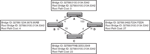
Consider the example shown in Figure 13.4. Notice that all switches have their default priority value of 32768 in their Bridge IDs. Thus, the lowest MAC address ultimately dictates who will win the election. Because Switch A has the lowest MAC address in the switched network, it will be the root bridge.

Exam Alert
Be prepared to be able to determine which switch is the root bridge, given a topology diagram of a switched LAN.
Because this election process occurs automatically with bridges and switches, it is highly advised that you change your priority in a robust and reliable switch in your internetwork as opposed to letting this election occur by chance. This is especially true because manufacturers choose the MAC address, and a lower MAC address could very well mean an old or low-end switch or bridge, which might not be the best choice for your root bridge. How to manually set the priority is discussed later in this chapter.
These Bridge IDs are advertised to each other through Bridge Protocol Data Units (BPDUs). These messages are sent as multicasts every 2 seconds by the root bridge out its interfaces to other switches on adjoining segments who, in turn, forward them on to other connected switches. In addition, these messages also contain the Bridge ID of the root bridge in every update that is sent. As long as you are receiving BPDUs that contain a higher Bridge ID than your Bridge ID, you will remain the root bridge (because all devices assume they are the root at startup).
In addition to the local bridge ID and the root bridge ID, BPDUs contain information that helps switches perform calculations to decide which ports should be forwarding and which should be blocking to create a loop-free switched network. The key to this calculation lies within the cumulative cost back to the root bridge. Although it sounds as if these Cisco switches are keeping track of how much you paid for them, this is not what is meant when you use the term “cost.” The cost is actually an inverse of the bandwidth for each link segment. Because it is the inverse, the lower the cumulative cost back to the root bridge, the faster the path is. Table 13.1 lists the standard costs used today in switches. It is possible to change these values administratively if you want to control which link becomes the best path to the root bridge.
After the root bridge is determined, each nonroot switch or bridge forms an association back to the root bridge based on the lowest cumulative path cost back to the root. Whichever interface has the fastest route to the root bridge automatically becomes a forwarding port called the root port.
Note
The root port is determined for the entire switch. Thus, each switch should contain only one root port back to the root bridge.
The root bridge advertises a root path cost of 0 to Switches B and D. As the BPDU enters their interfaces, they add the cost value of that interface and advertise that to any adjacent switches on other segments. Every nonroot bridge determines its fastest path back to the root by looking at these BPDUs that it receives from other switches. For instance, Switch B knows that going out of the top segment back to the root has a cost of 4, and going through Switch C has a cost of 42. Because the top segment has the lowest cumulative cost, that becomes the root port for Switch B.
What would happen if there were a tie in the root path cost? For instance, Switch C has two equal-cost paths of 23 back to the root bridge through Switch B and Switch D. In the event of a tie, the following are calculated to determine the root port:
The port with a switch advertising the lowest Bridge ID.
If the same Bridge ID (parallel links to the same switch), the lowest port priority is used. The port priority is an arbitrary number assigned to an interface that can be administratively set to choose one link over another. The default value is 128.
If the same port priority, the ultimate tiebreaker is the lowest interface number—for example, Fast Ethernet 0/1 over Fast Ethernet 0/6, because the links are identical.
Figure 13.5 expans on the switched networking example to include the path costs.

After every switch has determined its root port, the switches and bridges determine which port is to become the designated port for every segment that connects the two switches. As the name states, the designated port is the port on each interconnecting segment that is designated to forward traffic from that segment to another segment back to the root bridge. This too is determined through a calculation of the fastest way back to the root port. In the case of a tie, the same decision criteria applies to designated ports as root ports as described earlier.
In Figure 13.6, the designated ports have been calculated based on which switch is advertising the lowest cumulative cost back to the root on each segment. For instance, the BPDUs from Switch B to Switch C are advertising a root path cost of 19, whereas the BPDU being sent from Switch C to Switch B is advertising 38. Because Switch B has the lower root path cost, that is the designated port for that segment.

To this point, the discussion has focused on how to determine which ports will be forwarding traffic in a switched network. Yet to be addressed is the original point of STP, which is to remove any potential switching loops. To remove potential switching loops, switches and bridges keep any port that is not a root or designated port in a blocked state. Keep in mind that a blocked state is not disabled (shut down); the interface is just not participating in forwarding any data. Blocked interfaces still received BPDUs from other switches to react to any changes in the topology.
Exam Alert
Keep in mind for the exam that a blocked interface still receives BPDUs from other switches.
In Figure 13.7, notice that all the root ports have been elected, as well as the designated ports for each segment. Notice on the segment between Switch C and Switch D that a port connected to Switch C is not a root port or a designated port. This port blocks user data to ensure that a switching loop does not occur and expose the network to broadcast storms. This also means that any devices connected to Switch C sending Ethernet data to any device connected to Switch D will ultimately go through Switch B, and then Switch A, to finally arrive at Switch D.

Challenge
To ensure your understanding of STP, this challenge steps you through the scenario illustrated in Figure 13.8.
|

Figure 13.9 displays the end result of the STP election and calculation. Switch C becomes the root bridge in this design because the default priority was administratively changed in this design to 4096, giving Switch C the lowest Bridge ID. Because Switch A and Switch B are nonroot bridges, they must calculate their root ports based on the lowest cumulative cost back to the root bridge. For each segment, the switch with the lowest root path cost will be the designated port. Because Switch C’s interface on the lower segment is not a root or designated port, that interface will be blocking. |

You now know how STP removes switching loops in your switched LAN by electing a root bridge and calculating which ports should forward based on the lowest root path cost. However, as explained earlier, STP must be able to react to topology changes, such as a segment or switch going down, to ensure the redundant design is put to good use. When this type of change occurs, ports that were once in a blocking state could quite possibly transition to a forwarding state.
If devices were to immediately transition from a blocking state to a forwarding state, they could easily cause loops in the network because the topology change did not have a chance to propagate throughout the entire switched network. To remedy this dilemma, STP transitions into two intermediate states before moving to a forwarding role. In these transitionary states, the switch ensures that enough time has transpired to propagate the changes, and it undergoes a pre-forwarding routine to ensure that it will know where to forward the data when the interface is forwarding. Table 13.2 displays, in order, the possible STP states, their functions, and the time it takes to transition out of each state.
Table 13.2. STP Port States
State | Function | Transition Time |
|---|---|---|
Disabled | Interface is administratively shut down or inoperative as a result of a security violation. | N/A |
Blocking | Does not forward any user data. All ports start out in this state. Does not send, but still can receive BPDUs to react to topology changes. | 0 to 20 seconds |
Begins to transition to a forwarding state by listening and sending BPDUs. | 15 seconds | |
No user data sent. | ||
Begins to build MAC addresses learned on the interface. No user data sent. | 15 seconds | |
Forwarding | User data forwarded. |
It may initially take the switch 20 seconds to start the transition process to the listening stage because that is the default time limit that STP uses to consider a neighbor switch to be down. In other words, if a switch stops hearing 10 BPDUs (equal to 20 seconds) from an adjoining switch or bridge, it considers that device to be dead and must react to the new topology. This 20-second timer is known as the max age timer.
When a topology change occurs in the network, a nonroot switch sends a specific BPDU called a Topology Change Notification (TCN) out its root port back to the root bridge. This BPDU is one of the only times that a BPDU does not originate from the root bridge. As soon as the root bridge finally receives that notification, it broadcasts a special BPDU to all the switches in the network to start aging out old MAC entries in their CAM tables after about eight times faster (default is 300 seconds). At that point, the switches start rebuilding their CAM tables to reflect the new topology and forward frames accordingly.
The listening and learning states wait 15 seconds each by default, but can be administratively changed if you have a relatively small switched network. These 15-second intervals are commonly referred to as forward delays because they delay the transition to a forwarding state. It is important to consider that it could take up to 50 seconds for an interface to transition to a forwarding state when the topology changes. Consequently, no data is transferred in those 50 seconds—which in the networking world is about 10 phone calls of complaining end users.
The max age and forward delay timers are based on a default network diameter of seven switches including the root bridge. Diameter (in switching terms) refers to the number of bridge or switches between any two hosts. If your network is, for instance, only a diameter of 2, you can decrease these timers because it doesn’t take as long to propagate a change in the topology. Another benefit of STP is that these timers are ultimately dictated by the root bridge. Thus, to change the timers, you have to configure the change on only the root bridge, and it gets propagated to the other switches. This change could possibly backfire and cause switching loops in instances when you add more switches to the network and forget to change the timers. The next section discusses some safer alternatives to speed up the convergence time of STP when a topology change occurs.
Objective:
Perform and verify initial switch configuration tasks including remote access management
Catalyst switches, for the most part, are designed so that the default state of switch allows for basic Layer 2 functionality without requiring any configuration from the administrator. For example, the physical interfaces on the switch are already enabled, which means that you can plug a cable in the switch and the interface operates without requiring you to perform a no shutdown on that interface. Does that mean you don’t have to learn about Catalyst switch commands? No such luck.
The majority of the administrative configurations such as configuring hostnames, login banners, passwords, and Telnet/SSH access are identical to the configurations of the router IOS, as described in Chapter 7, “Foundation Cisco IOS Operations.” These next sections look at a few commands and configurations that are specific to Catalyst switches.
Cisco Layer 2 switches forward frames solely based on MAC addresses. On the other hand, Layer 3 switches and routers use IP addresses in their data forwarding decisions. So why assign an IP address to a Layer 2 switch?
Chapter 8, “Foundation Cisco Configurations,” mentions that to remotely manage a device via SSH, Telnet, or HTTP, you need to have IP connectivity to the switch. Likewise, if you were to manage the switch using SNMP, you would also have to program your management server to use its IP address to gather statistics from the switch. All these management functions assume that an IP address is assigned to the device, which in the Catalyst switch’s case does not have an IP address in its default configuration.
Unlike Cisco routers, Layer 2 switches do not assign IP addresses on all the physical interfaces. In fact, the interface to which you assign an IP address on a Layer 2 Catalyst switch is actually a virtual interface called VLAN 1. To assign an IP address to the entire switch, you use exactly the same syntax as a router’s physical interface to configure the VLAN 1 interface:
Switch(config)#interface VLAN1
Switch(config-if)#ip address 172.16.1.100 255.255.0.0
Switch(config-if)#no shutdown
01:35:19: %LINK-3-UPDOWN: Interface Vlan1, changed state to up
If you were to Telnet into the switch from the terminal on the far network, the Telnet traffic would traverse through the local router, across the WAN link, through the remote router, and finally to the switch. To return the Telnet traffic back to the terminal, the switch would have to send it to a routing device, because the terminal is on another network. To instruct the switch to send any traffic destined for another network to that router, you have to define a default gateway (also known as a gateway of last resort) as shown in Figure 13.10.
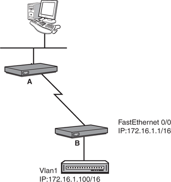
The command to configure a default gateway is ip default-gateway, followed by the IP address of the router that is on the switch’s segment in Global Configuration. Using the example in Figure 13.10, the configuration would look like the following:
Switch(config)#ip default-gateway 172.16.1.1Similar to router interfaces, the IP assigned to the VLAN 1 interface and the default gateway can be dynamically assigned using a DHCP server. The configuration is also similar to DHCP-assigned router interfaces except that the configuration is applied to the logical VLAN 1 interface as opposed to a physical port on the switch:
Switch#configure terminal
Enter configuration commands, one per line. End with CNTL/Z.
Switch(config)#interface vlan 1
Switch(config-if)#ip address dhcp
Switch(config-if)#no shutdown
00:58:49: %LINK-3-UPDOWN: Interface Vlan1, changed state to up
Interface Vlan1 assigned DHCP address 172.16.1.100, mask 255.255.0.0
After the ip address dhcp command is applied, the switch sends a DHCPDISCOVER broadcast out on all switch ports assigned to VLAN1 (by default, all switch ports are assigned to VLAN1). If a configured DHCP server exists on those segments, it replies with the IP address for the VLAN 1 interface and default gateway for the switch. As such, there is no required configuration of an IP address or default gateway in the switch configuration. It must be said, however, that despite the fact that this does simplify some of the administration configuration or reconfiguration tasks that are necessary to manage a switch, it is not practical because you need to readily know the IP address of the switch to effectively manage it.
Verifying the IP address and default gateway assigned by the DHCP server cannot be achieved by showing the running or startup configuration. Instead, you can use output from the show dhcp lease command to verify the IP address and default gateway:
Switch#show dhcp lease
Temp IP addr: 172.16.1.100 for peer on Interface: Vlan1
Temp  sub net mask: 255.255.0.0
   DHCP Lease server: 172.16.1.1, state: 3 Bound
   DHCP transaction id: 1967
   Lease: 16000 secs,  Renewal: 3000 secs,  Rebind: 16000 secs
Temp default-gateway addr: 172.16.1.1
   Next timer fires after: 00:00:32
   Retry count: 0   Client-ID: cisco-0019.e86a.6fc0-Vl1
Hostname: SwitchBy design, switches may have a plethora of interfaces that may require a similar configuration. For instance, if the first 20 ports of your switch need to be set to a speed of 100mbs and full duplex, you would be undertaking quite an administrative task of typing the same commands into each interface configuration for all 20 interfaces. To save time, the Catalyst switch’s IOS contains a navigation and configuration command shortcut called interface range that enables you to define a range of switch ports and configure them simultaneously. The configuration can be condensed to something like this:
Switch(config)#interface range FastEthernet 0/1 - 20
Switch(config-if)#speed 100
Switch(config-if)#duplex full
Verify network status and switch operation using basic utilities (including: ping, traceroute, telnet, SSH, arp, ipconfig), SHOW & DEBUG commands
STP is enabled by default on all Cisco Catalyst switches. To verify spanning tree operation in your switch, you can issue the show spanning-tree command to see a display of the STP operations:
Switch>show spanning-tree

VLAN0001
  Spanning tree enabled protocol ieee
  Root ID    Priority    32769
             Address     000c.65d0.4e00
             This bridge is the root
             Hello Time   2 sec  Max Age 20 sec  Forward Delay 15 sec

  Bridge ID  Priority    32769  (priority 32768 sys-id-ext 1)
             Address     000d.65d0.4e00
             Hello Time   2 sec  Max Age 20 sec  Forward Delay 15 sec
             Aging Time 15
Interface        Role Sts Cost      Prio.Nbr Type
---------------- ---- --- --------- -------- ----------------------------
Fa0/1            Desg LIS 19        128.1    P2p
Fa0/23           Desg FWD 19        128.23   P2p
Fa0/24           Back BLK 19        128.24   P2p
Notice in this output that you can see the MAC address and the priority of the root bridge and the local switch (which happens to be the root bridge). In addition, you can see the timers used in 802.1d for port state transitions, including the max age and forward delay. Finally, this useful show command displays the interfaces that are active and participating in STP and their associated role and state in the spanning tree network.
Objectives:
Verify network status and switch operation using basic utilities (including: ping, traceroute, telnet, SSH, arp, ipconfig), SHOW & DEBUG commands
Identify, prescribe, and resolve common switched network media issues, configuration issues, auto negotiation, and switch hardware failures
As always, when troubleshooting connectivity issues, use a layered approach and eliminate possibilities at each layer to home in on the possible cause of the problem. Over time, you will begin to develop a sixth sense about these problems and decrease the amount of effort it takes to accurately pinpoint a connectivity problem. In the meantime, let’s look at some possible connectivity scenarios and walk through some possible deductions as to what might cause the problem.
In instances where you cannot gain console connectivity to the switch, you should ask the following questions:
1. | Is the switch powered on and running? Although this seems like common sense, it is still valid to check to make sure the switch is powered on and successfully completed its bootup process. Catalyst switches all have LEDs (light-emitting diodes) on the switch face to signify that it is operating correctly. The system and status lights for the switch should both be a steady green if the device is powered on and operating normally. |
2. | Are your terminal connections correct? Verify that you have configured your terminal application correctly by setting the speed, flow control, and start and stop bits and ensure that you have the console (rollover) cable connected between your PC and the switch. |
3. | Did you or someone else change the console password? If you are gaining access to IOS but cannot log in, you may need to perform password recovery on the switch. Consult the switches’ manual or look online at cisco.com for switch-specific steps to recover your password. |
In instances where you cannot gain remote connectivity to the switch, you should ask the following questions:
In instances where the switch is not forwarding frames, you should ask yourself these questions:
This chapter has explored the mysteries behind Ethernet switching. Namely, it showed how switches build their MAC address table (also known as a CAM table), using the source MAC address of Ethernet frames, and forward, filter, or flood those frames based on the destination MAC. The method in which it forwards the frames differs from switch to switch. Specifically, the switch might use the latency varying store-and-forward transmission method, which buffers the entire frame and calculates the CRC before forwarding the frame. Cut-through switching looks at only the destination MAC address in an Ethernet frame, whereas fragment-free looks at up to the first 64 bytes, in which most collisions occur.
Switch connections can communicate in half duplex or full duplex, depending on the device to which they are connected. For instance, half-duplex connections are unidirectional and must be used when connecting to a hub because collisions must be detected. Full duplex can be used only when no possibility of collision exists, because it disables the collision detection circuitry to allow simultaneous bidirectional traffic. To ensure a collision-free environment for full-duplex connections, you must be directly connected to a switch.
When multiple switches are connected in a redundant design, STP (IEEE 802.1d) removes the possibility of switching loops, which can cause broadcast storms. It achieves this by electing a root bridge based on the lowest Bridge ID (priority + MAC) being advertised in BPDUs. After the root bridge is elected, every nonroot bridge forms an association to the root bridge by determining the port with the best path (lowest cumulative cost), which becomes the root port. For every segment, a designated port is also elected based on the fastest route back to the root bridge. In the event of a tie, the Bridge ID is used, followed by the lowest port priority, and finally the lowest port ID.
STP ports start in a blocking state, in which no data or BPDUs are being sent. If the port can forward frames, it transitions to a listening state for 15 seconds (forward delay), where it begins to exchange BPDUs. The learning stage follows for another 15 seconds to learn the MAC address on the interface and then finally transitions to a forwarding state.
This exercise reinforces the configurations involved in an initial setup of a Catalyst Switch. You may need to look back to Chapter 7 as a reference for some of the commands.
Estimated Time: 5 minutes
Power on your switch and enter user EXEC mode through the console.
In global configuration, assign the hostname, CstmrASwtch, create an appropriate login banner, and use the strongest encryption for access to privileged EXEC, using the password, giforgot.
Create a username of ccent with ssh4me as the password for SSH connectivity (requires cryptographic software image from Cisco.com).
In line configuration, specify Telnet and SSH as valid transport input protocols and to use the local username and password as the login on the first five vty lines.
Assign a management IP address of 172.16.31.30 /28.
Create the domain name of the switch to examcram.com.
Generate the RSA key for SSH.
Set the default gateway to be a hypothetical router address of 172.16.31.17 /28.
Using the
interface rangecommand, set the first three Fast Ethernet interfaces to be hardcoded as full duplex.Verify your active configuration and save it to NVRAM.
The configuration should look similar to the following Catalyst 3550 configuration:
Current configuration : 1819 bytes
!
version 12.2
no service pad
service timestamps debug uptime
service timestamps log uptime
no service password-encryption
!
hostname CstmrASwtch
!
enable secret 5 $1$ueGU$jTruyGB16bJKo9AIa8kkO/
!
username ccent password ssh4me
ip subnet-zero
!
!
ip domain name examcram.com
ip ssh time-out 60
ip ssh authentication-retries 2
!
!
spanning-tree mode pvst
spanning-tree extend system-id
!
!
interface FastEthernet0/1
 no ip address
 duplex full
!
interface FastEthernet0/2
 no ip address
 duplex full
!
interface FastEthernet0/3
 no ip address
 duplex full
!
!!!Output omitted...
!
interface GigabitEthernet0/1
 no ip address
!
interface GigabitEthernet0/2
 no ip address
!
interface Vlan1
 ip address 172.16.31.30 255.255.255.240
!
ip default-gateway 172.16.31.17
ip classless
ip http server
!
!
banner motd ^C This is a private system and may be accessed only by authorized users.
Unauthorized access is strictly prohibited and will be enforced to the full
extent of the law.^C
!
line con 0
line vty 0 4
login local
 transport input telnet ssh
line vty 5 15
login
!
end
What two components make up a Bridge ID? (Choose two)
| |||||||||
Considering the following output: Switch>show spanning-tree
VLAN0001
Spanning tree enabled protocol ieee
Root ID Priority 32768
Address 000c.418f.6542
Cost 19
Port 23 (FastEthernet0/23)
Hello Time 2 sec Max Age 20 sec Forward Delay 15 sec
Bridge ID Priority 32769 (priority 32768 sys-id-ext 1)
Address 000d.65d0.4e00
Hello Time 2 sec Max Age 20 sec Forward Delay 15 sec
Aging Time 300
Interface Role Sts Cost Prio.Nbr Type
---------------- ---- --- --------- -------- --------------------------------
Fa0/23 Root FWD 19 128.23 P2pwhich of the following is false?
| |||||||||
Given the following output: Switch>show spanning-tree
VLAN0001
Spanning tree enabled protocol ieee
Root ID Priority 32768
Address 000c.418f.6542
Cost 19
Port 23 (FastEthernet0/23)
Hello Time 2 sec Max Age 20 sec Forward Delay 15 sec
...Ouput Omitted...what speed is the interface?
| |||||||||
Which of the following can be determined from the following output? Switch>show spanning-tree
...Output Omitted...
Interface Role Sts Cost Prio.Nbr Type
---------------- ---- --- --------- -------- --------------------------------
Fa0/5 Root LRN 19 128.5 P2p
| |||||||||
Based on Figure 13.11, which of the following STP roles will Switch A and Switch D have on their shared link? (Choose two)
| |||||||||
Which frame transmission method is latency varying?
| |||||||||
Why is the following output false? Switch#show mac-address-table
Mac Address Table
-------------------------------------------
Vlan Mac Address Type Ports
---- ----------- -------- -----
...Output Omitted...
1 0300.3E9E.07E9 DYNAMIC Fa0/3
1 FFFF.FFFF.FFFF DYNAMIC Fa0/1
1 0300.3E3E.531A DYNAMIC Fa0/3
| |||||||||
What is the purpose of configuring a default gateway in a Catalyst switch?
| |||||||||
Which of the following are likely to occur when a switch with a higher Bridge ID is added to the switched topology? (Choose two)
| |||||||||
You just connected your interface to a hub. Which of the following must be true?
|
When a switch receives an Ethernet frame that contains an unknown source MAC address, it associates that MAC address with the receiving interface in the CAM table. When the switch receives an Ethernet frame with an unknown unicast destination MAC address, the switch floods that frame out every port except the one on which it was received. | |
Spanning Tree Protocol eliminates switching loops in environments when multiple switches are connected in a redundant design. | |
The root bridge is elected based on the switch that has the lowest advertised Bridge ID in the switches’ BPDUs. The Bridge ID is composed of the priority plus the switch’s MAC address. If another switch with a lower Bridge ID is added to the STP topology, a re-election occurs, and that switch becomes the new root bridge. | |
To gain IP connectivity to a Layer 2 switch, you must configure its management VLAN1 interface either manually with the | |
When you connect to a hub, collision detection must be enabled; thus, you must run the interface as half duplex. Full-duplex interfaces have collision detection disabled and can be enabled only when the switch port is connected to another switch or an end device. |
David Barnes and Basir Sakandar. Cisco LAN Switching Fundamentals. Cisco Press, 2004.
Matthew J. Castelli. LAN Switching First-Step, Cisco Press, 2004.
“Spanning-Tree Protocol,” www.cisco.com.