This chapter covers the following Cisco-specified objectives from the “Describe the operation of data networks” and “Implement a small switched network” sections of the 640-822 ICND1 exam:
<objective>Describe the purpose and functions of various network devices
</objective> <objective>Select the components required to meet a network specification
</objective> <objective>Use the OSI and TCP/IP models and their associated protocols to explain how data flows in a network
</objective> <objective>Interpret network diagrams
</objective> <objective>Explain the technology and media access control method for Ethernet networks
</objective> </feature><feature><title>Outline</title>84 | |||
84 | |||
84 | |||
86 | |||
87 | |||
87 | |||
91 | |||
93 | |||
93 | |||
94 | |||
94 | |||
95 | |||
95 | |||
96 | |||
96 | |||
96 | |||
96 | |||
97 | |||
97 | |||
98 | |||
99 | |||
100 | |||
100 | |||
101 | |||
104 | |||
105 | |||
106 | |||
107 | |||
107 | |||
109 | |||
109 | |||
110 | |||
110 | |||
114 | |||
115 | |||
117 | |||
Read the objectives at the beginning of the chapter.
Familiarize yourself with token ring and FDDI protocols.
Define the IEEE MAC unicast, broadcast, and multicast addresses.
Review the ethernet family of protocols and be able to identify the characteristics of each protocol.
Name the devices that are used at the Data Link layer and important traits of each device.
Define duplex.
Describe microsegmentation.
Several data link networking concepts were first introduced in the discussion of the Data Link layer or Layer 2 of the OSI model in Chapter 1, “Standard Internetworking Models.” Again, it is important to understand the layered architecture of the OSI model to grasp the fundamentals of how a network operates. Although Chapter 2, “Physical Layer Networking Concepts,” went over concepts that define the Physical layer of the OSI model, this chapter goes over concepts that define how a network operates at the Data Link layer specifically.
Important Data Link LAN topics to understand for the ICND1 exam include the protocols, addressing, and devices that are used at Layer 2. Cisco specified several objectives related to LAN technologies, which are prevalent at Layer 1 and Layer 2. Let’s begin with three Data Link layer protocols: token ring, FDDI, and ethernet.
Objectives:
Explain the technology and media access control method for Ethernet networks
Interpret network diagrams
Use the OSI and TCP/IP models and their associated protocols to explain how data flows in a network
In this section, you will learn about network protocols that can be utilized at the Data Link layer of the OSI model. These protocols include token ring, FDDI, and ethernet. Ethernet Data Link protocols are broken out into addressing and framing standards.
Token ring is a LAN protocol that utilizes a token-passing media access technology in a physical ring or physical star topology, which creates a logical ring topology. This protocol was first developed by IBM but then standardized by IEEE with the 802.5 specification. With token-passing, a three-byte token (or special bit pattern) is inserted in a frame and passed in a single direction from one node to another until it forms a complete loop. The node that has possession of the token is the only one that can send data at any given time on that LAN. Because only one node can send data at a time, collisions are avoided.
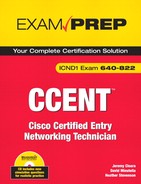
Rather than using a hub or switch, Token ring uses a multistation access unit (MAU) to send a token across the network. The MAU has Ring In (RI) and Ring Out (RO) ports. The RO of the first MAU is connected to the RI of the next MAU. This continues until the final MAU, which connects back to the first MAU RI port via its own RO port. As mentioned, a logical ring is created with this setup. Figure 3.1 shows how a token ring network operates with MAUs.
A token ring LAN can run at either 4Mbps or 16Mbps. Each device must be configured for the same speed; otherwise, the token-passing does not work at all. Overall, although this protocol provides a collision-free network, it is also more expensive to implement than ethernet. This is a major reason why ethernet is the most popular Data Link layer protocol, making token ring a rather distant second.
Let’s recap what you’ve learned about token ring:
Standardized by the IEEE 802.5 specification
A token-passing media access technology
Set up as a physical ring or physical star topology
Creates a logical ring topology
Speeds are assigned as either 4Mbps or 16Mbps
Provides collision-free data transfer
High overhead
FDDI is a LAN protocol that utilizes a token-passing media access method on a dual ring topology. This protocol was created by the American National Standards Institute (ANSI) with the ANSI X3T9.5 specification. Data transmission occurs on fiber-optic cables at a rate of 100Mbps. Primarily, FDDI was developed to run data across the network backbone of a larger company. Dual ring is configured for FDDI to provide redundancy and fault-tolerance. Also, because it runs over fiber it is not susceptible to EMI like other media options. Figure 3.2 shows the dual ring topology of an FDDI network.
Note
Copper Distributed Data Interface (CDDI) is a 100Mbps token-passing protocol that runs over copper wire rather than fiber-optic cable.
FDDI uses a method called beaconing to signal when a failure is detected on the network. Beaconing enables a device to send a signal informing the other devices on that LAN that token passing has stopped. The beacon travels around the loop from one device to the next until it reaches the last device in that ring. To troubleshoot, the network administrator can find the beacon at that last device and then check the connection between that device and the next connected device on the FDDI network.
Like token ring, FDDI is costly to implement, which is a disadvantage when designing a small network.
Let’s recap what you’ve learned about FDDI:
Developed by ANSI with the ANSI X3T9.5 specification
A token-passing media access technology
Set up as a dual ring topology
Speed is 100Mbps
Runs over fiber-optic cable
Not susceptible to EMI
Provides collision-free data transfer
Fault-detection provided by beaconing
High overhead
Ethernet, ethernet, ethernet . . .
The most popular LAN by a mile, ethernet is a group of protocols and standards that work at either the Physical or Data Link layer of the OSI model. This section covers ethernet technology that is relevant to Layer 2. Ethernet is defined by the IEEE 802.3 specification. As technology advancements occur, IEEE has defined additional classifications of 802.3, which include Fast Ethernet, Gigabit Ethernet, 10-Gigabit Ethernet, and Long Reach Ethernet. The physical implementations of each Ethernet standard are covered in greater detail in a moment, but first I would like to review ethernet addressing and ethernet framing. Ethernet addressing can be achieved with unicast, multicast, or broadcast addresses at the Data Link layer.
The Data Link layer uses physical or hardware addressing to make sure data is delivered to the appropriate end device in a LAN. Physical addresses or what are commonly referred to as MAC addresses are used at Layer 2. Before you go any further, it’s a good idea to take a minute to review what you learned in Chapter 1.
The Data Link layer of the OSI model is the only one that has sublayers. Table 3.1 shows the breakout of Layer 2.
Table 3.1. Data Link Layer and Sublayers
OSI Model Layer | Sublayer |
|---|---|
Data Link Layer | Media Access Control (MAC) IEEE 802.3 |
Logical Link Control (LLC) IEEE 802.2 |
A MAC address is hard-coded (burnt in) on the network interface controller (NIC) of the Physical Layer device attached to the network. Each MAC address must be unique and use the following format:
It must be displayed by 12 hexadecimal digits (0–9, A–F).
The first 6 hexadecimal digits in the address are a vendor code or organizationally unique identifier (OUI) assigned to that NIC manufacturer.
The last 6 hexadecimal digits are assigned by the NIC manufacturer and must be different from any other number assigned by that manufacturer.
An example of a MAC address would be 00:00:07:A9:B2:EB. The OUI in this example is 00:00:07.
Exam Alert
MAC Address Structure Know that a MAC address consists of 48 bits and is expressed as 12 hexadecimal digits from either 0–9 or A–F. Also, know that the vendor code or OUI is the first 6 hexadecimal digits of the MAC address.
Note
Check out an actual example of a physical address on your own PC. From the Start menu, select Run. Then type in cmd to enter the command prompt for your PC. You should see a new window open on the screen where you can type in ipconfig/all at the prompt. Among other things, the output includes the physical or MAC address of your PC.
Ethernet LAN addresses can be broken down into two subcategories: individual and group addresses. An individual address is referred to as a unicast address. A unicast address identifies the MAC address of an individual LAN or NIC card. The source address on an ethernet frame will always be a unicast address. When a packet from the Network layer is framed for transport and is being forwarded to a single destination, a unicast address is also the destination address on an ethernet frame. Figure 3.3 represents an example of frame forwarding between a unicast source and a unicast destination device. Cisco devices typically use three groups of four hexadecimal digits separated by periods, such as 0000.0C12.3456. Cisco’s OUI is 0000.0C.
In the example in Figure 3.3, Bill’s computer checks the destination address on the ethernet frame. If the destination address is the MAC on his computer, the frame is processed. If the destination address does not match up, the frame is dropped.
Group Ethernet LAN addresses classify more than one LAN or NIC card. Multicast and broadcast addresses are both classified as group addresses and can be described as follows:
Multicast addresses—. Addresses where a frame can be sent to a group of devices in the same LAN. IEEE ethernet multicast addresses always begin with 0100.5E in hexadecimal format. The last three bytes can be any combination of hexadecimal digits. The IP routed protocol supports multicast addressing with three groups of four hexadecimal digits separated by periods (like Cisco devices), so it appears as 0100.5Exx.xxxx, where the x’s can represent any hex digit from 0–9 or A–F. Figure 3.4 shows a frame that is being forwarded from a unicast source to an IP multicast destination address.
In this example, the switch sends a frame from its own unicast address to the multicast address of 0100.5E12.3456. Each device in that LAN segment checks the destination address to see whether it should be processed. Although Bill and Carol’s computer will review and process the frame, Dustin’s does not care about it and therefore drops the frame.
Broadcast addresses—. Addresses where a frame is sent to all devices in the same LAN segment. Multicast and broadcast addresses are limited to a LAN or network segment. Broadcast addresses are always the same value, which is FFFF.FFFF.FFFF. Figure 3.5 shows a switch sending a frame to the destination address FFFF.FFFF.FFFF. Because this is the broadcast address value, all the devices in that LAN should process the frame.
As you will recall from Chapter 1, data traverses the layers of the OSI model and is encapsulated from layer to layer.
Table 3.2 shows the process of using the OSI model to encapsulate data.
The Data Link layer uses frames to transport data between layers. Framing is the process of interpreting data that is either received or sent out across the network. The 802.2 LLC Data Link sublayer is an extension of 802.3 and is responsible for framing, error-detection, and flow control. Figure 3.6 represents an 802.3 frame.
Exam Alert
For the ICND1 exam, review the structure of the 802.3 frame, specifically, the Destination/Source MAC address fields of the data-link header, the DSAP/SSAP fields of the LLC portion of the frame, and the FCS field of the Data and CRC data-link trailer.
The three main parts of an 802.3 frame can be broken down and described as follows:
The Data Link header portion of the frame contains the destination MAC address (6 bytes), source MAC address (6 bytes), and length (2 bytes).
The Logical Link Control portion of the frame contains Destination Service Access Point (DSAP), Source Service Access Point (SSAP), and control information. All three are 1 byte long. The Service Access Point (SAP) identifies an upper-layer protocol such as IP (06) or IPX (E0).
The data and cyclical redundancy check (CRC) portion of the frame is also called the data-link trailer. The data field can be anywhere from 43 to 1497 bytes long. The frame check sequence (FCS) field is 4 bytes long. FCS or CRC provides error detection.
Error detection is used to determine whether bit errors happened during frame transmission. The sender and receiver of a frame use the same mathematical formula to analyze the information in the FCS field of the data-link trailer. If the calculations match up, there were no errors on that frame transmission.
Select the components required to meet a network specification
Have I said that ethernet is the most popular LAN protocol? Ethernet started in the 1970s when Xerox needed a networking system to connect personal computers. Xerox joined forces with Digital Equipment Corp. (DEC) and Intel to develop the protocol, which is why the very first ethernet standards were referred to as DIX Ethernet. This section covers the progression of ethernet standards from the earlier 10Mbps connections to the more recent 10 gigabit ethernet connections.
Each standard has a maximum connection length and speed. Individual ethernet standards also specify which cables and connectors can be used for network connectivity. You will be introduced to each group of standards starting with the 10Mbps ethernet connections, then the 100Mbps Fast Ethernet connections, 1Gbps ethernet, and 10Gbps ethernet connections.
The IEEE 802.3 ethernet standards are covered in the following sections. The following list contains all the ethernet standards that are covered in this chapter, in order:
10BASE2 networks are connected with RG-58 coaxial cables that use Bayonet Neill Concelman (BNC) connectors. There are no other hardware devices such as hubs or switches to connect devices, just the coaxial cables. This creates a physical bus topology. An electrical signal is sent by each device that wants to transmit data on that network. If more than one device sends a signal at the same time, this causes a collision and the signal is lost. To prevent loss of data transmissions, an algorithm called Carrier Sense Multiple Access Collision Detection (CSMA/CD) was defined. This algorithm sends a jam signal to notify the devices that there has been a collision. The devices then halt transmission for a random back-off time. CSMA/CD must be activated for 10Base ethernet LANs that are connected with a hub.
Exam Alert
For the exam, know the definition of CSMA/CD and its capability to act as an arbitrator for devices in an ethernet LAN.
The name 10BASE2 breaks down as follows:
10BASE5 has the same characteristics as 10BASE2, but with a maximum segment length of 500m. The 5 is also a multiple of 100m.
10BASE-T has a maximum segment length of 100m and has a 10Mbps data transmission speed. 10BASE-T can use Category 3, 4, or 5 unshielded twisted-pair (UTP) or shielded twisted-pair (STP) cables for connectivity. If you recall, UTP is the more common and cost-effective solution. STP has an additional shield that provides additional reduction of interference and attenuation, but it is also the more expensive solution. The following cables can be used with a 10BASE-T connection:
Category 3—. Data cable that can handle speeds up to 10Mbps.
Although it is faster than the Cat2 cable, this was quite popular until network speeds surpassed the 10Mbps threshold.
Category 4—. Data cable that can handle speeds up to 16Mbps and is meant to be used with token ring LANs.
Category 5—. Data cable that can handle speeds up to 100Mbps and is currently the most popular cable selection.
10BASE-FL also has a 10Mbps data transmission speed, but it runs over fiber-optic cables. This option allows for a maximum segment length up to 2km.
Table 3.3 compares the 802.3 ethernet characteristics, listing the key characteristics of each specification.
As you can see, the early standards are all limited to 10Mbps. More recent ethernet specifications allow for faster data transmission speeds and are more popular for today’s networks.
Fast Ethernet was derived for networks that needed speeds in excess of 10Mbps. The IEEE 802.3u defines standards for 100BASE-T4, 100BASE-TX, and 100BASE-FX. You may also hear them collectively referred to as 100BASE-X. Based on what you learned from the 10Base naming scheme, you would be correct to infer that the 100 represents 100Mbps. Also, all three standards are baseband like the 10Mbps family of protocols.
100BASE-T4 has the same characteristics as 100BASE-TX except that it can use Category 3, 4, or 5 UTP or STP cables.
100BASE-TX, like 10BASE-T, uses either UTP or STP. Category 5 UTP cable is used with this implementation. 10BASE-T has a maximum segment length of 100m.
100BASE-FX uses either single-mode or multimode fiber-optic cables to connect. Multimode (MM) fiber set for half-duplex can reach a distance of 412m. Single-mode (SM) fiber set for full-duplex can reach a distance of 10,000m. SC or ST connectors can be used. The drawback, as mentioned before with fiber implementations, is the high overhead.
Multimode (MM) fiber—. This is generally used for shorter distances and is ideal for a campus-sized network. MM also has a larger diameter of optical fiber than SM fiber.
Single-mode (SM) fiber—. This mode is used to span longer distances. SM also allows for a higher data rate than MM and faster data transmission speeds.
Gigabit Ethernet standards all have a data transmission speed of 1000Mbps (1Gbps) and use a baseband signaling mode. Gigabit Ethernet can be broken down into two IEEE standards, 802.3ab or 1000BASE-T and 802.3z or 1000BASE-X.
1000BASE-T or 1000BASE-TX is defined by the 802.3ab standard and can reach a maximum total distance per segment of 75m. This standard uses a minimum of Category 5 UTP cable with an RJ-45 connector.
Category 5e—. Data cable that can handle speeds up to 1Gbps; a popular choice for Gigabit Ethernet networks.
Category 6—. Cable that was created to exceed speeds of 1Gbps.
Table 3.5 summarizes the primary points of interest that are relevant for the 1000BASE-T standard.
1000BASE-X is the collective name for 802.3z standards 1000BASE-CX, 1000BASE-SX, and 1000BASE-LX that have the following characteristics respectively:
1000BASE-CX—. 1000BASE-CX is the unique standard in this family because it uses shielded copper wire cable with a 9-pin shielded connector instead of fiber-optic cable for connectivity. The maximum total distance per segment is a mere 25m.
1000BASE-SX—. 1000BASE-SX transmits short-wavelength laser over fiber-optic cable. Either 50-micron or 62.5-micron (diameter) MM fiber can be used with this option. Lengths may vary depending on the type of MM fiber and duplex chosen for each connection as follows:
Half-duplex 62.5-micron MM fiber connections can reach a maximum segment length of 275m.
Half-duplex 50-micron MM fiber connections can reach a maximum segment length of 316m.
Full-duplex 62.5-micron MM fiber connections can reach a maximum segment length of 275m.
Full-duplex 50-micron MM fiber connections can reach a maximum segment length of 550m.
As you can see, the 50-micron MM fiber can offer longer segment distances. The 62.5-micron MM fiber reaches the same maximum segment length of 275m regardless of the duplex.
1000BASE-LX—. 1000BASE-LX transmits long-wavelength laser over fiber-optic cable. Either 50-micron or 62.5-micron (diameter) MM fiber can be used with this option. SM fiber can also be used with 1000BASE-LX, which differentiates this standard from 1000BASE-SX. The same MM fiber length restrictions apply based on the implementation of half- or full-duplex. The following lengths apply when SM fiber is used:
Half-duplex SM fiber connections can reach a maximum segment length of 316m.
Full-duplex SM fiber connections can reach a maximum segment length of 5000m.
Using full-duplex SM fiber allows for a huge increase in distance. As you can imagine, this is also the more expensive option.
Table 3.6 compares Fast Ethernet 802.3z standards.
Table 3.6. Comparison of Gigabit Ethernet 802.3z Characteristics
Standard | Speed | Maximum Distance | Media Type | Connector Used |
|---|---|---|---|---|
1000BASE-CX | 1000Mbps or 1Gbps | 25m | Shielded copper wire connector | 9-pin shielded |
1000BASE-SX | 1000Mbps or 1Gbps | 275m with half or full-duplex | MM fiber-optic | SC or ST |
62.5-micron MM fiber | ||||
316m with half-duplex | ||||
50-micron MM fiber | ||||
550m with full-duplex | ||||
50-micron MM fiber | ||||
1000BASE-LX | 1000Mbps or 1Gbps | 275m with half- or full-duplex | MM or SM fiber-optic | SC or ST |
62.5-micron MM fiber | ||||
316m with half-duplex | ||||
50-micron MM fiber or SM fiber | ||||
550m with full-duplex | ||||
50-micron MM fiber | ||||
5000m with full-duplex | ||||
SM fiber |
You guessed it: 1Gbps just wasn’t a fast enough option. Actually, it is just the nature of technology to constantly strive for faster speeds. Yet another new standard was defined by IEEE and labeled 802.3ae. Earlier in this chapter, you saw 10BASE-2, which has data transmission speeds of 10Mbps. 10-Gigabit Ethernet transmits data at 10,000Mbps. That is quite an upgrade! IEEE 802.3ae uses 62.5-micron MM, 50-micron MM, or SM fiber-optic cabling for connectivity and a baseband signaling mode.
Cisco Long Reach Ethernet (LRE) was developed to provide broadband service over existing telephone-grade or Category 1, 2, or 3 wiring. Speeds vary between 5–15Mbps and can reach a maximum segment length of up to 5000m. Cisco LRE may be a viable networking solution for a LAN or MAN that already has Category 1/2/3 cabling installed. A hotel could benefit from Cisco LRE to provide high-speed Internet or video conferencing solutions to their clientele.
Objective:
Describe the purpose and functions of various network devices
At the Data Link layer, either a bridge or a Layer 2 switch can be installed to segment a LAN. Hubs and repeaters at the Physical layer only serve to extend a network. With segmentation, switches and bridges create a separate collision domain for each connected node, which effectively reduces the number of collisions that occur on that network.
Remember from Chapter 1 that a collision domain is a group of nodes that shares the same media and are segmented by switches or bridges. A collision occurs if two nodes attempt a simultaneous transmission within the same collision domain. This reinforces the need for an increased number of collision domains. Figure 3.7 demonstrates how a bridge creates two collision domains.
Figure 3.8 provides an example of a situation in which a switch creates separate collision domains.
Exam Alert
Know what a collision domain is and that a bridge and/or switch will segment a network and create an additional collision domain for each segment. Routers not only segment collision domains, but they also segment broadcast domains.
Bridges were created to alleviate several expansion-related network issues. As networks were growing and becoming more complex, hubs and repeaters no longer provided sufficient network resources. Because they do not segment the network, all the devices connected to a hub or repeater had to share the same bandwidth. Also, if one device sent a frame, it could collide with a frame from another device on that LAN. This meant that all devices on that LAN had to take turns sending frames. Again, this is not very efficient as additional devices are added to a network.
Transparent bridges were introduced and helped solve these growing pains. The word transparent is used to indicate that the other devices on a network are not aware of its existence. Bridges use a software application to forward frames.
The following are the primary tasks performed by both bridges and switches:
The source MAC address of every inbound frame is examined to learn its MAC address.
Frames may either be forwarded or filtered depending on the destination MAC address (they can also be flooded if the destination is unknown).
Eliminates loops that are caused by redundant connections by configuring Spanning Tree Protocol (STP).
Learned MAC addresses and their interfaces are stored in a bridge table on the bridge or switch. When a new frame arrives on that bridge or switch, the device refers to the bridge table to decide how to forward or filter the frame. If the frame’s destination MAC address is on a different segment of that LAN, the device forwards the frame to that segment. If the frame’s destination MAC address is on the same segment as the source MAC address, the device filters the frame. That frame reaches its destination without the assistance of a bridge or switch. Figure 3.9 shows a segmented LAN with the MAC addresses of each end user.
As frames are received by the bridge or switch from each end user, it updates its bridge table with their MAC addresses and the interface on which the frame came into the device. Table 3.7 shows the bridge table of this bridge.
Table 3.7. Example Bridge Table for Figure 3.9
MAC Address | Interface |
|---|---|
0200.1111.1111 | E0 |
0200.2222.2222 | E0 |
0200.3333.3333 | E1 |
0200.4444.4444 | E1 |
If the incoming frame destination address is...
Unicast—. The bridge checks the bridge table first. If the destination unicast address is not in the bridge table, it forwards the frame to all interfaces except for the interface that originally sent the frame. If the destination unicast address is in the bridge table and on a different interface than the interface that originally sent the frame, it forwards the frame. If the destination unicast address is in the bridge table and on the same interface as the sender, the frame is filtered.
Multicast—. The bridge forwards the frame to all interfaces except for the interface that originally sent the frame.
Broadcast—. The bridge forwards the frame to all interfaces except for the interface that originally sent the frame.
Challenge
Based on what you just learned about bridge and switch frame filtering or forwarding, take a look at Figure 3.10 and fill out the bridge table for this network that is using a switch for connectivity.
<division> <title>Bridge Table</title>
Address | Interface |
|---|---|
Using the same diagram and your new bridge table, I will give you a source and destination address. Please fill out whether the frame will be filtered or forwarded. If it is forwarded, also fill out the outbound interface to which the frame will be sent.
Layer 2 switches are multi-port bridges; therefore, they have all the same functionality of bridges. There are differences that differentiate a switch from a bridge. For example, switches utilize hardware or Application-Specific Integrated Circuit (ASIC) chips to forward frames rather than software. Also, each port of the switch has a dedicated bandwidth. If the dedicated port on a switch is 10Mbps, the connected LAN segment has a dedicated bandwidth of 10Mbps. This works in the same manner for 100Mbps and 1000Mbps dedicated switch ports. This feature also sets a switch apart from a bridge that has a low port density.
Exam Alert
For the test, know that switches are multi-port bridges that use ASIC hardware chips for frame forwarding. Dedicated bandwidth enables the switch port to guarantee the speed assigned to that port. For example, 100Mbps port connections get 100Mbps transmission rates.
A popular ethernet switch port is the 10/100 ethernet port, where you can set the port to pass traffic at 10Mbps or 100Mbps. Chapter 6, “Introduction to Cisco Routers and Switches,” goes into more detail regarding specific Cisco devices, including the 2950 series switches.
It is important that you understand duplex logic and how it affects traffic on a network. The communication mode of a device may either be half-duplex or full-duplex, depending on the connection type.
Half-duplex allows for one-way communication, which means that a device can only send or receive a data transmission at any given time. This option does not allow for simultaneously sending and receiving data. As part of a shared collision domain, hubs are inherently set up for half-duplex. Bandwidth suffers because a collision detection technology such as the CSMA/CD algorithm must be implemented. Collision detection can chew up 50–60% of the bandwidth on that ethernet LAN.
Full-duplex allows for two-way communication, which means that a device can simultaneously send and receive data transmissions. Full-duplex is available with dedicated switch port connections to a single device. If a switch port connection is configured for full-duplex, the CSMA/CD algorithm must be disabled. An ethernet connection set for full-duplex allows for 100% transmission speeds in both directions. For example, a 100Mbps connection can transmit data simultaneously at 100Mbps in each direction.
With ethernet, if a switch port and NIC offer multiple speed options as well as half- and full-duplex settings, autonegotiation can be configured on both devices. The switch and NIC automatically negotiate the connection speed and duplex so that the settings on both ends match. You may have heard of a 10/half or 100/full connection before. The term 10/half refers to a 10Mbps half-duplex connection. It is more likely that you will see 100/full, which indicates a 100Mbps full-duplex connection.
Note
Autonegotiation may not always be a reliable option. There have been some instances where the switch port goes into error disable mode because of massive errors. Configuring or “hard coding” the port and NIC to the appropriate speed and duplex settings may resolve the issue when the port is reactivated.
Microsegmentation occurs when a switch creates a dedicated path for sending and receiving transmissions with each connected host. Each host then has a separate collision domain and a dedicated bandwidth.
Many important functions occur at the Data Link layer of the OSI model. Different technologies can be implemented at Layer 2 to transmit data across the network. Token ring and FDDI networks use token-passing to send frames, whereas ethernet uses the 802.3 frame standard with 802.2 LLC specifications. Ethernet framing and ethernet addressing are both significant topics for the ICND1 exam. Other key ethernet functions include error detection and arbitration. Although the FCS field of the 802.3 frame detects errors on a LAN, the CSMA/CD algorithm arbitrates how data is transmitted on a LAN.
Data Link layer devices include bridges and switches. Switches are really multi-port bridges, so they share the same general functionalities. New networks are most likely to use a Layer 2 switch in place of a bridge. Switches have been improved upon over the years and offer more options for the consumer, such as dedicated bandwidth and full-duplex communications.
Although the Data Link layer uses frames to transmit data, the Network layer uses Internet Protocol or IP addresses to route traffic. Chapter 5 discusses IP addressing and subnetting at length. Both topics are imperative for the ICND1 exam.
You may be asked to identify the standards associated with IEEE Ethernet on the CCNA exam. In this exercise, I am listing the ethernet specification and want you to complete the table to include the IEEE-defined standard, the associated speed, and the cable or media type used for each specification. You may refer back to Tables 3.4, 3.5, 3.6, and 3.7 to check your answers.
Estimated Time: 10 minutes
Token-passing is a Data Link protocol that inserts a three-byte token (or special bit pattern) into a frame and passes it around the network in a single direction from one node to another until it forms a complete loop. The node that has possession of the token is the only one that can send data at any given time on that LAN. Because only one node can send data at a time, collisions are avoided. | |
Standardized by the IEEE 802.5 specification A token-passing media access technology Set up as a physical ring or physical star topology Creates a logical ring topology Speeds are assigned as either 4Mbps or 16Mbps Utilizes an MSAU rather than a switch or hub Provides collision-free data transfer High overhead | |
Developed by ANSI with the ANSI X3T9.5 specification A token-passing media access technology Set up as a dual ring topology Redundant, fault-tolerant network Speed is 100Mbps Runs over fiber-optic cable Not susceptible to EMI Provides collision-free data transfer Fault-detection provided by beaconing High overhead | |
A unicast address identifies the MAC address of an individual LAN or NIC card. A multicast address forwards a frame to a subset of devices in the same LAN. IEEE ethernet multicast addresses always begin with 0100.5E in hexadecimal format. The last three bytes can be any combination. A broadcast address sends a frame to all devices in the same LAN. Broadcast addresses are always the same value, which is FFFF.FFFF.FFFF. | |
CSMA/CD or Carrier Sense Multiple Access Collision Detection is an algorithm that sends a jam signal to notify the devices that there has been a collision. The devices then halt transmission for a random back-off time. | |
The primary tasks performed by both bridges and switches are as follows: The source MAC address of every inbound frame is examined to learn its MAC address. You can decide whether to forward or filter a frame based on the destination MAC address. Eliminate loops that are caused by redundant connections by configuring Spanning Tree Protocol (STP). | |
Half-duplex allows for one-way communication, which means that a device can only send or receive a data transmission at any given time. As a part of a shared collision domain, hubs must use half-duplex. Full-duplex allows for two-way communication, which means that a device can simultaneously send and receive data transmissions. Full-duplex is available with dedicated switch port connections to a single device. If a switch port connection is configured for full-duplex, the CSMA/CD algorithm must be disabled. Also, an ethernet connection set for full-duplex allows for 100% transmission speeds in both directions. | |
Microsegmentation occurs when a switch creates a dedicated path for sending and receiving transmissions with each connected host. Each host then has a separate collision domain and a dedicated bandwidth. |
D. IEEE 802.5 defines token ring. Answers A, B, and C are incorrect because IEEE 802.2 defines LLC, 802.3a defines ethernet, and 802.3u defines Fast Ethernet. | |
C. ANSI X3T9.5 defines FDDI. Answers A, B, and D are incorrect because they are all IEEE standards. IEEE 802.5 defines token ring, 802.3u defines Fast Ethernet, and 802.2 defines LLC. | |
A. Token-passing inserts a three-byte token (or special bit pattern) into a frame and passes it in a single direction from one node to another until it forms a complete loop. Answers B, C, and D are all incorrect because unicast, multicast, and broadcast are all types of ethernet addresses. | |
B, D. Token ring and FDDI use token-passing to send frames. Answers A and C are incorrect because Fast Ethernet and Gigabit Ethernet both use 802.3 MAC and 802.2 LLC headers and trailers for framing. | |
A. Unicast addresses identify the MAC address of an individual LAN or NIC card. Answer B is incorrect because multicast addresses send a frame to a group of devices in the same LAN. Answer C is incorrect because broadcast addresses send a frame to all the devices in the same LAN. Answer D is incorrect because a token is a special bit pattern used with token-passing networks. | |
A, D. Both 0000.0C12.3456 and 0200.1111.1111 are unicast addresses. 0000.0C is Cisco’s OUI. Answers B and C are incorrect because 0100.5E12.3456 is a multicast address and FFFF.FFFF.FFFF is a broadcast address. | |
B. Multicast addresses send a frame to a subset of devices in the same LAN. Answer A is incorrect because unicast addresses identify the MAC address of an individual LAN or NIC card. Answer C is incorrect because broadcast addresses send a frame to all the devices in the same LAN. Answer D is incorrect because a token is a special bit pattern used with token-passing networks. | |
B. 0100.5E12.3456 is a multicast address. Multicast addresses always start with 0100.5E. Answers A and D are incorrect because both 0000.0C12.3456 and 0200.1111.1111 are unicast addresses. Answer C is incorrect because FFFF.FFFF.FFFF is a broadcast address. | |
C. Broadcast addresses send a frame to all the devices in the same LAN. Answer A is incorrect because unicast addresses identify the MAC address of an individual LAN or NIC card. Answer B is incorrect because multicast addresses send a frame to a subset of devices in the same LAN. Answer D is incorrect because a token is a special bit pattern used with token-passing networks. | |
C. Broadcast addresses are always represented as FFFF.FFFF.FFFF. Answers A and D are incorrect because both 0000.0C12.3456 and 0200.1111.1111 are unicast addresses. Answer B is incorrect because 0100.5E12.3456 is a multicast address. | |
B. Frames are used by the Data Link layer to transport data between the Network and Physical layer. Framing is the process of interpreting data that is either received or sent out across the network. Answers A, C, and D are incorrect because bits are used at the Physical layer, packets are used at the Network layer, and segments are used at the Transport layer of the OSI model. | |
D. The frame check sequence (FCS) field of a frame uses a mathematical formula to determine whether any bit errors occurred during data transmission. Answer A is incorrect because Service Access Point (SAP) identifies the upper-layer protocol such as IP. Answer B is incorrect because DSAP is the destination SAP or destination upper-layer protocol. Answer C is incorrect because SSAP is the source SAP or the source upper-layer protocol. | |
B, C. IEEE 802.3ab and 802.3z define Gigabit Ethernet standards. Answers A and D are incorrect because 802.3u defines the Fast Ethernet standard, and 802.3ae defines the 10 Gigabit Ethernet standard. | |
A. Collision domains are increased with the addition of bridges or switches on a network. Answer B is incorrect because routers create additional broadcast domains. Answers C and D are incorrect because unicast and multicast are both addresses used by ethernet. | |
C. The source MAC address of an incoming frame is examined by a bridge or switch to learn the MAC address for the bridge table. Answers A and B are incorrect because multicast and broadcast addresses can never be the source MAC address. Answer D is incorrect because the destination MAC address is not used by a bridge or switch to create the bridge table. | |
D. Switches use ASIC hardware chips for frame forwarding. Answers A and B are incorrect because hubs and repeaters do not forward frames because they are Physical layer or Layer 1 devices. Answer C is incorrect because bridges use software for frame forwarding. | |
A. 10Mbps is guaranteed with dedicated bandwidth on a 10Mbps ethernet LAN. Answers B, C, and D are incorrect because other speeds of 100, 1000, and 10,000Mbps are all faster speeds that require a different ethernet LAN standard. | |
D. Spanning Tree Protocol (STP) is a Data Link protocol that eliminates loops caused by redundant connections on a LAN. Answers A and B are incorrect because cyclical redundancy check (CRC) and frame check sequence (FCS) both provide error detection. Answer C is incorrect because CSMA/CD is an algorithm that is used for arbitration on an ethernet network. | |
C. Half-duplex allows for only one-way data transmissions at any time. Answers A and B are incorrect because 10Mbps and 100Mbps are speed classifications primarily associated with ethernet LANs. Answer D is incorrect because full-duplex allows for two-way data transmissions. | |
D. Full-duplex allows for simultaneous two-way data transmissions. Answers A and B are incorrect because 10Mbps and 100Mbps are speed classifications primarily associated with ethernet LANs. Answer C is incorrect because half-duplex allows for only one-way data transmissions at any time. |
The following are some recommended readings for LAN networking and related terminology:
“TechEncyclopedia,” www.techweb.com/encyclopedia.
“RFC 1700,” www.isi.edu/in-notes/rfc1700.txt.
“Layer 1 & 2,” www.hojmark.net/layer1-2.html#lan.
“Cisco Long-Reach Ethernet,” www.cisco.com/warp/public/779/servpro/solutions/long_ethernet/.
Barnes, David and Sakandar, Basir. Cisco LAN Switching Fundamentals. Cisco Press, 2004.