Chapter 10
Configure and Verify VLANs and Interswitch Connectivity
This is a critical chapter. Your ability to build the Layer 2 logical structure of a LAN is very important. This structure includes VLANs, trunks, and sometimes EtherChannels. All of these technologies are tackled in this chapter.
This chapter covers the following essential terms and components:
▸ Virtual local-area networks (VLANs)
▸ Data access ports
▸ Voice access ports
▸ The default VLAN
▸ Interswitch links
▸ Trunk ports
▸ 802.1Q
▸ The native VLAN
▸ EtherChannel
▸ LACP
▸ PAgP
Topic: Configure, verify, and troubleshoot VLANs (normal range) spanning multiple switches
CramSaver
If you can correctly answer these CramSaver questions, save time by skimming the ExamAlerts in this section and then completing the CramQuiz at the end of this section and the Review Questions at the end of the chapter. If you are in doubt at all, read everything in this chapter!
1. From an IP perspective, what does a VLAN equate to?
_________
2. What is the default VTP mode on a Cisco switch?
_________
3. What VTP mode effectively disables VTP?
_________
4. What command would you use to create VLAN 30?
_________
5. What is the default VLAN on a Cisco switch?
_________
6. What protocol allows a Cisco IP phone to function properly with the voice VLAN and the Cisco switch?
_________
Answers
1. A VLAN equates to an IP subnet.
2. The default VTP mode is Server.
3. VTP Transparent mode effectively disables VTP. Some switches also support the Off mode in addition to Server, Client, and Transparent.
4. The command vlan 30 creates VLAN 30. The creation of the VLAN occurs when exiting VLAN configuration mode.
5. VLAN 1
6. Cisco Discovery Protocol (CDP)
A virtual local-area network (VLAN) is a broadcast domain you create on a switch. This domain also corresponds to a TCP/IP subnet. Figure 10.1 shows an example of VLANs created on a Cisco switch.

Figure 10.1 VLANs on a Cisco Switch
Cisco provides VLAN Trunking Protocol (VTP) to assist with VLAN creation and synchronization across many switches. In fact, this is why the word Trunking appears in the name. In order for VLAN creation to automatically span switches, the switches must be connected with special interswitch links called trunks. (The next section of this chapter focuses on trunks.)
Note
Trunks is the term Cisco uses for ports that can carry traffic for more than one VLAN. Other equipment vendors use different terms, such as tagged ports.
Example 10.1 shows the default VTP status of a Cisco switch.
Example 10.1 The Default VTP Status for a Cisco Switch
Switch# show vtp status
VTP Version capable      : 1 to 3
VTP version running      : 1
VTP Domain Name          :
VTP Pruning Mode         : Disabled
VTP Traps Generation     : Disabled
Device ID                : fa16.3ebb.cb23
Configuration last modified by 0.0.0.0 at 0-0-00 00:00:00
Local updater ID is 0.0.0.0 (no valid interface found)

Feature VLAN:
--------------
VTP Operating Mode               : Server
Maximum VLANs supported locally  : 1005
Number of existing VLANs         : 5
Configuration Revision           : 0
MD5 digest                       : 0x57 0xCD 0x40 0x65 0x63 0x59 0x47 0xBD
                                   0x56 0x9D 0x4A 0x3E 0xA5 0x69 0x35 0xBC
Switch#
In Example 10.1, note that VTP Operating Mode is set to Server by default. This means you can create and modify VLANs on this local device, and any such change will propagate throughout the network. In addition, Transparent mode basically disables VTP, whereas Client mode allows switches to inherit the VLAN information from a server(s). Note that you cannot create VLANs locally on a VTP client device.
Example 10.2 shows the creation of a VLAN on a Cisco switch.
Example 10.2 Creating a VLAN on a Cisco Switch
Switch(config)# vlan 20
Switch(config-vlan)# name EAST
Switch(config-vlan)# end
Switch#
%SYS-5-CONFIG_I: Configured from console by console
Switch#
ExamAlert
Example 10.3 demonstrates several critical points that are likely to be tested on the CCNA 200-301 exam. Notice that one powerful command for verifying VLANs is show vlan brief. Also notice that the new VLAN WEST does not appear in the output because you have not exited config-vlan mode. Also, if you want to configure a hostname for the switch itself, you use the hostname command from global configuration mode. The limits for the hostname are 63 characters, letters, numbers, or hyphens and no spaces. The name also must begin and end with a letter or number.
Example 10.3 Configuring and Verifying a VLAN
Switch# configure terminal
Enter configuration commands, one per line. End with CNTL/Z.
Switch(config)# vlan 30
Switch(config-vlan)# name WEST
Switch(config-vlan)# do show vlan brief
VLAN Name                           Status     Ports
---- ------------------------------ ---------- -------------------
1    default                         active     Gi0/0, Gi0/1, Gi0/2,
                                               Gi0/3
                                               Gi1/0
20   EAST                           active
1002 fddi-default                   act/unsup
1003 token-ring-default             act/unsup
1004 fddinet-default                act/unsup
1005 trnet-default                  act/unsup
Switch(config-vlan)#
Notice that there is a VLAN 1 by default on a Cisco switch and that all non-trunk ports are listed as participants of this VLAN. This is termed the default VLAN. It is a best practice to remove all ports from the default VLAN. Typically, engineers create a special unused VLAN for any ports they are not using on the switch. By default, two hosts connected to the same switch are in separate collision domains (one per port), but they are both part of the same Layer 2 broadcast domain and VLAN.
What good is a VLAN if interfaces (ports) are not participating in it? Example 10.4 demonstrates the configuration of an interface for participation in a data VLAN as well as the simple verification.
Example 10.4 Configuring and Verifying an Interface for a VLAN
Switch# configure terminal
Enter configuration commands, one per line. End with CNTL/Z.
Switch(config)# interface gi0/1
Switch(config-if)# switchport mode access
Switch(config-if)# switchport access vlan 20
Switch(config-if)# end
Switch#
%SYS-5-CONFIG_I: Configured from console by console
Switch# show vlan brief
VLAN Name                  Status     Ports
---- --------------------- ---------  ----------------------
1    default               active     Gi0/0, Gi0/2, Gi0/3, Gi1/0
20   EAST                  active     Gi0/1
30   WEST                  active
40   TEST                  active
1002 fddi-default          act/unsup
1003 token-ring-default    act/unsup
1004 fddinet-default       act/unsup
1005 trnet-default         act/unsup
Switch#
ExamAlert
Another big concern for the CCNA 200-301 exam is the configuration of a voice VLAN for IP phones to use. Example 10.5 demonstrates voice VLAN configuration and verification. Note that the Cisco Discovery Protocol (CDP) is required for Cisco IP phones to function properly with this configuration. Because CDP is running and enabled on every port by default on Cisco switches, no configuration for CDP is shown here.
Example 10.5 Configuring and Verifying a Voice VLAN
Switch# configure terminal
Enter configuration commands, one per line. End with CNTL/Z.
Switch(config)# vlan 50
Switch(config-vlan)# name VOICE
Switch(config-vlan)# exit
Switch(config)# interface gi0/2
Switch(config-if)# switchport mode access
Switch(config-if)# switchport access vlan 30
Switch(config-if)# switchport voice vlan 50
Switch(config-if)# end
Switch#
%SYS-5-CONFIG_I: Configured from console by console
Switch# show vlan brief
VLAN Name                           Status     Ports
---- ------------------------------ ---------- -------------------
1    default                         active    Gi0/0, Gi0/3, Gi1/0,
20   EAST                            active    Gi0/1
30   WAST                            active    Gi0/2
40   TAST                            active
50   VOICE                           active    Gi0/2
1002 fddi-default                   act/unsup
1003 token-ring-default             act/unsup
1004 fddinet-default                act/unsup
1005 trnet-default                  act/unsup
Switch# show interface gi0/2 switchport
Name: Gi0/2
Switchport: Enabled
Administrative Mode: static access
Operational Mode: static access
Administrative Trunking Encapsulation: negotiate
Operational Trunking Encapsulation: native
Negotiation of Trunking: Off
Access Mode VLAN: 30 (WEST)
Trunking Native Mode VLAN: 1 (default)
Administrative Native VLAN tagging: enabled
Voice VLAN: 50 (VOICE)
Administrative private-vlan host-association: none
Administrative private-vlan mapping: none
Administrative private-vlan trunk native VLAN: none
Administrative private-vlan trunk Native VLAN tagging: enabled
Administrative private-vlan trunk encapsulation: dot1q
Administrative private-vlan trunk normal VLANs: none
Administrative private-vlan trunk associations: none
Administrative private-vlan trunk mappings: none
Operational private-vlan: none
Trunking VLANs Enabled: ALL
Pruning VLANs Enabled: 2-1001
Capture Mode Disabled
Capture VLANs Allowed: ALL

Protected: false
Appliance trust: none
Switch#
Notice in the output in Example 10.5 that the show interface switchport command is used to verify the voice VLAN configuration.
CramQuiz
1. Your 48-port Cisco switch has been configured with five different VLANs. How many broadcast domains exist on the switch?
![]() A. 0
A. 0
![]() B. 1
B. 1
![]() C. 5
C. 5
![]() D. 48
D. 48
2. What command allows you to easily verify the VTP mode?
![]() A. show vtp mode
A. show vtp mode
![]() B. show vtp status
B. show vtp status
![]() C. show vtp server
C. show vtp server
![]() D. show vtp brief
D. show vtp brief
3. What VTP mode would prevent you from creating a VLAN on the local switch?
![]() A. Client
A. Client
![]() B. Server
B. Server
![]() C. Transparent
C. Transparent
![]() D. Off
D. Off
4. What command allows you to view the VLANs and interface assignments on a switch?
![]() A. show vlan brief
A. show vlan brief
![]() B. show vlan status
B. show vlan status
![]() C. show vlan summary
C. show vlan summary
![]() D. show vlan database
D. show vlan database
5. What command assigns an access port to VLAN 20?
![]() A. switchport vlan 20
A. switchport vlan 20
![]() B. switchport mode vlan 20
B. switchport mode vlan 20
![]() C. switchport assign vlan 20
C. switchport assign vlan 20
![]() D. switchport access vlan 20
D. switchport access vlan 20
6. What command assigns voice VLAN 10 on a switch access port?
![]() A. switchport voice vlan 10
A. switchport voice vlan 10
![]() B. switchport access vlan 10 voice
B. switchport access vlan 10 voice
![]() C. switchport vlan 10 voice
C. switchport vlan 10 voice
![]() D. switchport access vlan 10
D. switchport access vlan 10
7. What command allows you to verify the voice VLAN configuration?
![]() A. show interface gi0/1 voice
A. show interface gi0/1 voice
![]() B. show interface gi0/1 switchport
B. show interface gi0/1 switchport
![]() C. show interface gi0/1 vlan
C. show interface gi0/1 vlan
![]() D. show interface gi0/1 vlan assign
D. show interface gi0/1 vlan assign
CramQuiz Answers
1. C is correct. Each VLAN is a broadcast domain. If there are five VLANs defined on the switch, you have five broadcast domains.
2. B is correct. The show vtp status command allows you to verify many basic VTP parameters.
3. A is correct. Client mode prevents local VLAN creation.
4. A is correct. The show vlan brief command allows you to easily verify the VLANs and the interface assignments.
5. D is correct. The command is switchport access vlan 20.
6. A is correct. The command is switchport voice vlan 10.
7. B is correct. The command show interface gi0/1 switchport is very powerful and displays verbose information regarding the interface configuration, including the voice VLAN.
Topic: Configure, verify, and troubleshoot interswitch connectivity
CramSaver
1. What is the most common Ethernet trunking protocol in use today?
_________
2. What is the name of the VLAN that is not tagged on an Ethernet trunk?
_________
3. What is the default native VLAN on Cisco IOS switches?
_________
4. Why are administrators typically concerned about the native VLAN?
_________
How does traffic from different VLANs move from switch to switch? Over a trunk link—specifically, an 802.1Q trunk link.
Cisco originally created its own method of marking traffic with a VLAN ID for transport over an interswitch link. It was called Inter-Switch Link (ISL), and it took an interesting approach: ISL fully encapsulated the frame in order to add a VLAN marking. 802.1Q takes a different approach: It injects a 32-bit tag in the existing frame. Figure 10.2 shows the 802.1Q approach, which is inserted between the Source MAC and Type fields of the Ethernet header. 802.1Q allows multiple VLANs to be supported over a single trunk interface.

Figure 10.2 The 802.1Q Tag
Here is the breakdown of these values:
▸ Tag protocol identifier (TPID): A 16-bit field set to the value 0x8100 in order to identify the frame as an IEEE 802.1Q-tagged frame.
▸ Tag control information (TCI): This section consists of the following:
▸ Priority code point (PCP): A 3-bit field that refers to the IEEE 802.1p class of service and maps to the frame priority level.
▸ Drop eligible indicator (DEI): A 1-bit field that may be used separately or in conjunction with PCP to indicate frames eligible to be dropped in the presence of congestion.
▸ VLAN identifier (VID): A 12-bit field specifying the VLAN to which the frame belongs.
Example 10.6 demonstrates the configuration and verification of 802.1Q trunking on a Cisco switch.
Example 10.6 Configuring and Verifying Trunking
Switch# configure terminal
Enter configuration commands, one per line. End with CNTL/Z.
Switch(config)# interface gi1/0
Switch(config-if)# switchport trunk encapsulation dot1q
Switch(config-if)# switchport mode trunk
Switch(config-if)# end
Switch#
%SYS-5-CONFIG_I: Configured from console by console
Switch# show interface gi1/0 switchport
Name: Gi1/0
Switchport: Enabled
Administrative Mode: trunk
Operational Mode: trunk
Administrative Trunking Encapsulation: dot1q
Operational Trunking Encapsulation: dot1q
Negotiation of Trunking: On
Access Mode VLAN: 1 (default)
Trunking Native Mode VLAN: 1 (default)
Administrative Native VLAN tagging: enabled
Voice VLAN: none
Administrative private-vlan host-association: none
Administrative private-vlan mapping: none
Administrative private-vlan trunk native VLAN: none
Administrative private-vlan trunk Native VLAN tagging: enabled
Administrative private-vlan trunk encapsulation: dot1q
Administrative private-vlan trunk normal VLANs: none
Administrative private-vlan trunk associations: none
Administrative private-vlan trunk mappings: none
Operational private-vlan: none
Trunking VLANs Enabled: ALL
Pruning VLANs Enabled: 2-1001
Capture Mode Disabled
Capture VLANs Allowed: ALL
Protected: false
Appliance trust: none
Switch# show interface trunk

Port   Mode   Encapsulation  Status    Native vlan
Gi1/0  on     802.1q         trunking  1

Port   Vlans allowed on trunk
Gi1/0  1-4094

Port   Vlans allowed and active in management domain
Gi1/0  1,20,30,40,50

Port   Vlans in spanning tree forwarding state and not pruned
Gi1/0  1,20,30,40,50
Switch#
By default, there is a very special VLAN in the 802.1Q infrastructure: the native VLAN. This VLAN is not tagged. It is the only untagged VLAN on a trunk link. By default, the native VLAN is VLAN 1—the default VLAN. Why would Cisco introduce a native VLAN feature? The idea is to use it for management traffic so that this critical traffic can still flow between devices, even if a link loses its trunking status. CDP messages (as well as DTP and VTP messages) are sent over the native VLAN by default.
CramQuiz
1. Where is an 802.1Q tag inserted in a frame?
![]() A. Between the Preamble and SFD fields
A. Between the Preamble and SFD fields
![]() B. Between the Source and Destination MAC fields
B. Between the Source and Destination MAC fields
![]() C. Between the Source MAC and Type fields
C. Between the Source MAC and Type fields
![]() D. Between the Source MAC and FCS fields
D. Between the Source MAC and FCS fields
2. What command configures an interface to trunk?
![]() A. switchport trunk
A. switchport trunk
![]() B. switchport trunk dot1q
B. switchport trunk dot1q
![]() C. switchport mode trunk
C. switchport mode trunk
![]() D. switchport trunk enable
D. switchport trunk enable
3. What command allows you to quickly view all the trunks on a switch?
![]() A. show vlans trunk
A. show vlans trunk
![]() B. show interface trunk
B. show interface trunk
![]() C. show trunk interface
C. show trunk interface
![]() D. show trunk all
D. show trunk all
4. What is the native VLAN feature intended to carry?
![]() A. Security traffic
A. Security traffic
![]() B. Monitoring traffic
B. Monitoring traffic
![]() C. Voice VLAN traffic
C. Voice VLAN traffic
![]() D. Management traffic
D. Management traffic
5. What methods can a network engineer use to stop security issues with the native VLAN? (Choose two.)
![]() A. Eliminate VLAN 1.
A. Eliminate VLAN 1.
![]() B. Disable VLAN 1.
B. Disable VLAN 1.
![]() C. Tag the native VLAN.
C. Tag the native VLAN.
![]() D. Use an unused VLAN for the native VLAN.
D. Use an unused VLAN for the native VLAN.
CramQuiz Answers
1. C is correct. The tag is inserted between the Source MAC and Type fields.
2. C is correct. The command is switchport mode trunk.
3. B is correct. The command is show interface trunk.
4. D is correct. The native VLAN is intended to carry management traffic in the event that the 802.1Q trunking function fails.
5. C and D are correct. Today, engineers should tag the native VLAN or use an unused VLAN for the native VLAN. Doing so reduces some vulnerabilities.
Topic: Configure, verify, and troubleshoot (Layer 2/Layer 3) EtherChannel
CramSaver
1. What technology aggregates multiple physical links so they can act as one link?
_________
2. What are three options for EtherChannel configuration?
_________
The EtherChannel capability of Cisco switches is often included as part of Spanning Tree Protocol discussions. Why? Because EtherChannel tricks Spanning Tree Protocol and solves a similar problem. EtherChannel involves bundling together multiple links between two Cisco switches to act as a single link. Spanning Tree Protocol gets tricked by this, and it does not block any link within an EtherChannel bundle. Of course, Spanning Tree Protocol might need to block the entire bundle in order to avoid Layer 2 loops, but bundles that are not blocked enjoy the redundancy and increased bandwidth that EtherChannel provides.
To create EtherChannels, you must use interfaces that are of the same type and capabilities from a physical perspective. You should also ensure that they are configured identically.
The number of EtherChannels that a switch supports varies from device to device. A typical number supported for many Cisco switches is eight total EtherChannels. Figure 10.3 shows a topology used in this chapter for configuring, verifying, and troubleshooting the various EtherChannel configurations.
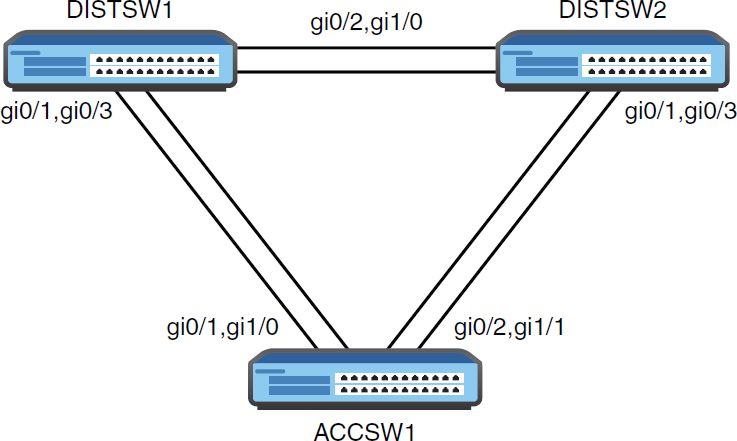
Figure 10.3 A Sample EtherChannel Topology
Example 10.7 demonstrates the configuration of a static Layer 2 EtherChannel.
Example 10.7 Configuring a Static EtherChannel
DISTSW1# configure terminal
Enter configuration commands, one per line. End with CNTL/Z.
DISTSW1(config)# interface range gi0/1 , gi0/3
DISTSW1(config-if-range)# shutdown
DISTSW1(config-if-range)#
%LINK-5-CHANGED: Interface GigabitEthernet0/1, changed state to administratively down
%LINK-5-CHANGED: Interface GigabitEthernet0/3, changed state to administratively down
DISTSW1(config-if-range)# channel-group 1 mode on
DISTSW1(config-if-range)# end
DISTSW1#
DISTSW1#

ACCSW1#
ACCSW1# configure terminal
Enter configuration commands, one per line. End with CNTL/Z.
ACCSW1(config)# interface range gi0/1 , gi1/0
ACCSW1(config-if-range)# channel-group 1 mode on
Creating a port-channel interface Port-channel 1

ACCSW1(config-if-range)# end
ACCSW1#

DISTSW1#
DISTSW1# configure terminal
Enter configuration commands, one per line. End with CNTL/Z.
DISTSW1(config)# interface range gi0/1 , gi0/3
DISTSW1(config-if-range)# no shutdown
DISTSW1(config-if-range)# end
DISTSW1#
Notice the following about the configuration shown in Example 10.7:
▸ The interface range command configures the two interfaces simultaneously.
▸ Issuing the shutdown command first prevents EtherChannel misconfiguration errors as the other side of this link defaults to the use of PAgP for dynamically configuring an EtherChannel. When statically configuring an EtherChannel, neither LACP nor PAgP is used.
▸ The channel-group command creates the EtherChannel; the ID 1 is locally significant only, and the mode on indicates a static configuration.
▸ When the other side of the link (ACCSW1) possesses the same configuration, we issue the command no shutdown for the interfaces on DISTSW1.
But does the configuration in Example 10.7 work? Example 10.8 demonstrates how easy it is to verify the EtherChannel.
Example 10.8 Verifying a Static EtherChannel
DISTSW1#
DISTSW1# show etherchannel 1 summary
Flags: D - down         P - bundled in port-channel
       I - stand-alone  s - suspended
       H - Hot-standby (LACP only)
       R - Layer3       S - Layer2
       U - in use       N - not in use, no aggregation
       f - failed to allocate aggregator

       M - not in use, minimum links not met
       m - not in use, port not aggregated due to minimum links not met

       u - unsuitable for bundling
       w - waiting to be aggregated
       d - default port

       A - formed by Auto LAG

Number of channel-groups in use: 1
Number of aggregators:
Group  Port-channel   Protocol    Ports
------+-------------+-----------+----------------------------
1      Po1(SU)          -         Gi0/1(P) Gi0/3(P)
DISTSW1#
Notice the following from the output in Example 10.8:
▸ The configuration creates a logical port channel interface with an ID of 1.
▸ The port channel interface is Layer 2 (S) and in use (U).
▸ The physical interfaces are labeled as bundled in a port channel (P).
Next, let’s look at the creation of a Layer 2 EtherChannel using the built-in and default dynamic method Port Aggregation Protocol (PAgP). There are two settings possible here: auto and desirable. Example 10.9 demonstrates this configuration and verification.
Example 10.9 Using PAgP to Form a Layer 2 EtherChannel
ACCSW1#
ACCSW1# configure terminal
Enter configuration commands, one per line. End with CNTL/Z.
ACCSW1(config)# interface range gi0/2 , gi1/1
ACCSW1(config-if-range)# channel-group 2 mode desirable
Creating a port-channel interface Port-channel 2

ACCSW1(config-if-range)# end
ACCSW1#

DISTSW2#
DISTSW2# configure terminal
Enter configuration commands, one per line. End with CNTL/Z.
DISTSW2(config)# interface range gi0/1 , gi0/3
DISTSW2(config-if-range)# channel-group 2 mode desirable
Creating a port-channel interface Port-channel 2

DISTSW2(config-if-range)# end
DISTSW2#
DISTSW2# show etherchannel summary
Flags: D - down         P - bundled in port-channel
       I - stand-alone  s - suspended
       H - Hot-standby (LACP only)
       R - Layer3       S - Layer2
       U - in use       N - not in use, no aggregation
       f - failed to allocate aggregator
       M - not in use, minimum links not met
       m - not in use, port not aggregated due to minimum links not met
       u - unsuitable for bundling
       w - waiting to be aggregated
       d - default port

       A - formed by Auto LAG

Number of channel-groups in use: 1
Number of aggregators:

Group  Port-channel  Protocol    Ports
------+-------------+-----------+-------------------------
2      Po2(SU)       PAgP        Gi0/1(P) Gi0/3(P)

DISTSW2#
Next, let’s look at the creation of a Layer 2 EtherChannel using Link Aggregation Control Protocol (LACP) for automatic negotiation, as shown in Example 10.10. This mode uses Active or Passive settings. Notice that here we again use the shutdown approach on the interfaces to avoid the misconfiguration errors that occur with the default mode of PAgP for some Cisco switches.
Example 10.10 Using PAgP to Form a Layer 2 EtherChannel
DISTSW1#

DISTSW1# configure terminal
DISTSW1(config)# interface range gi0/2 , gi1/0
DISTSW1(config-if-range)# shutdown
DISTSW1(config-if-range)# channel-group 3 mode active
Creating a port-channel interface Port-channel 3

DISTSW1(config-if-range)# end
DISTSW1#

DISTSW2#
DISTSW2# configure terminal
Enter configuration commands, one per line. End with CNTL/Z.
DISTSW2(config)# interface range gi0/2 , gi1/0
DISTSW2(config-if-range)# channel-group 3 mode active
Creating a port-channel interface Port-channel 3

ISTSW2(config-if-range)# end
DISTSW2#
DISTSW1#
DISTSW1# configure terminal
DISTSW1(config)# interface range gi0/2 , gi1/0
DISTSW1(config-if-range)# no shutdown
DISTSW1(config-if-range)# end
DISTSW1#
DISTSW1#
DISTSW1# show etherchannel 3 summary
Flags: D - down P - bundled in port-channel
       I - stand-alone s - suspended
       H - Hot-standby (LACP only)
       R - Layer3 S - Layer2
       U - in use N - not in use, no aggregation
       f - failed to allocate aggregator

       M - not in use, minimum links not met
       m - not in use, port not aggregated due to minimum links not met

       u - unsuitable for bundling
       w - waiting to be aggregated
       d - default port

       A - formed by Auto LAG

Number of channel-groups in use: 1
Number of aggregators:

Group  Port-channel  Protocol    Ports
------+-------------+-----------+-------------------------------
3      Po3(SU)       LACP        Gi0/2(P)       Gi1/0(P)

DISTSW1#
Configuring a Layer 3 EtherChannel is also simple. Example 10.11 demonstrates this configuration after all previous configurations to DISTSW1 have been removed. Remember that static, LACP, and PAgP options all still exist. Also keep in mind that you create the port channel interface first and then assign it an IP address in the case of the Layer 3 EtherChannel.
Example 10.11 Configuring a Layer 3 EtherChannel
DISTSW1#
DISTSW1# configure terminal
DISTSW1(config)# interface port-channel 1
DISTSW1(config-if)# no switchport
DISTSW1(config-if)# ip address 10.10.10.1 255.255.255.0
DISTSW1(config-if)# exit
DISTSW1(config)# interface range gi0/1 , gi0/3
DISTSW1(config-if-range)# no switchport
DISTSW1(config-if-range)# shutdown
DISTSW1(config-if-range)# channel-group 1 mode on
DISTSW1(config-if-range)# no shutdown
DISTSW1(config-if-range)# end
DISTSW1#
CramQuiz
1. What is the default EtherChannel mode on a Cisco switch?
![]() A. PAgP
A. PAgP
![]() B. LACP
B. LACP
![]() C. Static
C. Static
![]() D. NULL
D. NULL
2. Where do you assign the IP address in a Layer 3 EtherChannel?
![]() A. The physical interfaces
A. The physical interfaces
![]() B. The port channel interface
B. The port channel interface
![]() C. The NVI interface
C. The NVI interface
![]() D. Global configuration mode
D. Global configuration mode
3. What command creates an LACP EtherChannel with local ID 10?
![]() A. channel-group 10 mode active
A. channel-group 10 mode active
![]() B. channel-group 10 mode desirable
B. channel-group 10 mode desirable
![]() C. channel-group 10 mode on
C. channel-group 10 mode on
![]() D. channel-group 10 mode enable
D. channel-group 10 mode enable
CramQuiz Answers
1. A is correct. The default mode is PAgP.
2. B is correct. The IP address is configured at the port channel interface.
3. A is correct. The LACP options are Active and Passive.
Review Questions
1. What protocol helps you create VLANs across different devices with ease?
![]() A. VTP
A. VTP
![]() B. Spanning Tree Protocol
B. Spanning Tree Protocol
![]() C. SPAN
C. SPAN
![]() D. CDP
D. CDP
2. What must you do in order to place VLAN 20 in the VLAN database on your local device?
![]() A. Exit config-vlan mode.
A. Exit config-vlan mode.
![]() B. Restart the device.
B. Restart the device.
![]() C. Place the device in Client mode.
C. Place the device in Client mode.
![]() D. Save the running configuration.
D. Save the running configuration.
3. What is the default VLAN in Cisco networking?
![]() A. VLAN 10
A. VLAN 10
![]() B. VLAN 0
B. VLAN 0
![]() C. VLAN 4092
C. VLAN 4092
![]() D. VLAN 1
D. VLAN 1
4. How big is the VID field inside of the 802.1Q tag?
![]() A. 12 bits
A. 12 bits
![]() B. 16 bits
B. 16 bits
![]() C. 32 bits
C. 32 bits
![]() D. 64 bits
D. 64 bits
5. Which keyword is used to statically configure an EtherChannel?
![]() A. auto
A. auto
![]() B. active
B. active
![]() C. on
C. on
![]() D. desirable
D. desirable
Answers to Review Questions
1. A is correct. VTP allows you to configure or modify VLANs on a central device and then have these configurations synchronize across multiple switches.
2. A is correct. To complete a VLAN configuration, you must exit config-vlan mode.
3. D is correct. VLAN 1 is the default VLAN in Cisco.
4. A is correct. The VID field is 12 bits in size.
5. C is correct. Use the on keyword when creating the EtherChannel in order to statically configure the bundle. Note that this avoids both PAgP and LACP.
Hands-On Lab Practice Assignment
Configure Trunks
To complete this Hands-On Lab Practice Assignment, download the assigned Packet Tracer file from the book’s companion website and perform the lab on your locally installed version of Packet Tracer. For instructions on how to download and use the Packet Tracer files, see “Packet Tracer Hands-On Lab Practice Assignments” in the Introduction of this book.
Additional Resource
Ethernet Switch Configuration—Part 2 (VLANs)