
Chapter 6. Cisco Cloud Infrastructure
This chapter covers the following topics:
1.0 Cloud Infrastructure Administration and Reporting
1.3 Deploy virtual app containers
1.3.a Provide basic support and troubleshoot app container with firewall, networking, and load balancer
3.0 Cloud Provisioning
3.1 Describe predefined Cisco UCS Director-based services with the Cisco Prime Service Catalog
3.1.c Describe template formats
Task 3.1.c(iii): Network
Task 3.1.c(iv): Virtualization
3.3 Deploy preconfigured templates and make minor changes to the service catalog offerings that do not affect workflows or services
3.3.a Describe the deployment of templates: storage, compute, network, and virtualization
As you have seen in previous chapters, a cloud infrastructure is composed of a variety of components, from physical switches, storage arrays, and compute node to many virtual appliances. Each of these has a key function in the operation and administration of a cloud infrastructure, and this chapter looks at both the virtual and physical components necessary to build a cloud infrastructure suited for automation and orchestration.
This chapter starts with an overview of the main Cisco and third-party products that can be connected into a Cisco Powered cloud for automation and orchestration. The main virtual and physical components that make up an on-premises cloud infrastructure will be reviewed. The major sections provide an overview of the physical and virtual switches, the virtual appliances, the compute components, storage, and Cisco Intercloud Fabric. We’ll then summarize how these components can be joined together to work in a Cisco Powered cloud.
“Do I Know This Already?” Quiz
The “Do I Know This Already?” quiz allows you to assess whether you should read this entire chapter thoroughly or jump to the “Exam Preparation Tasks” section. If you are in doubt about your answers to these questions or your own assessment of your knowledge of the topics, read the entire chapter. Table 6-1 lists the major headings in this chapter and their corresponding “Do I Know This Already?” quiz questions. You can find the answers in Appendix A, “Answers to the ‘Do I Know This Already?’ Quizzes.”
Caution
The goal of self-assessment is to gauge your mastery of the topics in this chapter. If you do not know the answer to a question or are only partially sure of the answer, you should mark that question as wrong for purposes of the self-assessment. Giving yourself credit for an answer you correctly guess skews your self-assessment results and might provide you with a false sense of security.
1. You can connect using SSH into which of the following switches to manage them? (Choose all that apply.)
a. Nexus 1000V Series
b. Nexus 2000 Series
c. Nexus 5000 Series
d. Nexus 7000 Series
e. Nexus 9000 Series
f. All of the above
2. FEX stands for:
a. Fabric Enhanced Extension
b. Fabric Ethernet Extension
c. Fabric Extender
d. Fiber Extender
3. The Nexus 9000 line of switches supports which of the following GE port speeds?
a. 1/10
b. 1/10/100
c. 10/100
d. 1/10/25/40/50/100
e. 10/50/100
4. What are the main components of the Nexus 1000V? (Choose all that apply.)
a. Virtual Ethernet Module
b. Logical Ethernet Module
c. Logical Supervisor Module
d. Virtual Supervisor Module
e. Application Policy Connector
5. AVS stands for:
a. Application Velocity System
b. Application Virtual System
c. Application Virtualized System
d. Application Virtual Switch
6. For an ACI-enabled network, which would be the best product to use to deliver virtual switching services?
a. VMware NSX
b. Nexus 1000V
c. VMware DVS
d. Application Virtual Switch
7. Which of the following are not benefits of VACS? (Choose all that apply.)
a. Easy installation within UCS Director
b. Port-based firewall
c. Zone-based firewall
d. Hardware-based load balancing
e. All the above are benefits of VACs
8. Choose all the valid VACS container types.
a. 2 Tier
b. n Tier
c. 3 Tier Internal
d. 3 Tier External
9. Which of the following can be a VACS container gateway of choice? (Choose all that apply.)
a. The built-in virtual gateway, the CSR 1000V
b. A physical gateway such as one from Palo Alto Networks
c. A logical gateway within the application tier of an n-tier software application
d. Another virtual gateway such as the ASAv, vGW, or vPAN
e. None of the above
10. What level(s) of encryption is supported by Intercloud secure network extension? (Choose all that apply.)
a. AES 128 bit
b. AES 256 bit
c. AES 512 bit
d. AES 1024 bit
e. None of the above
Foundation Topics
How Automation and Orchestration Relates to Infrastructure
The underlying physical and virtual infrastructure within your private on-premises data center is the “pool of resources” that you can control by a cloud automation and orchestration suite. It is important to understand how automation and orchestration relates to infrastructure (whether physical or virtual) and how all the pieces fit together to help you deliver the types of services required by your organization. This chapter discusses products and technologies such as the Cisco Nexus Series Switches, Application Centric Infrastructure (ACI), Virtual Application Cloud Segmentation (VACS), Nexus 1000V, Virtual Security Gateway (VSG), Cloud Services Router (CSR), and more.
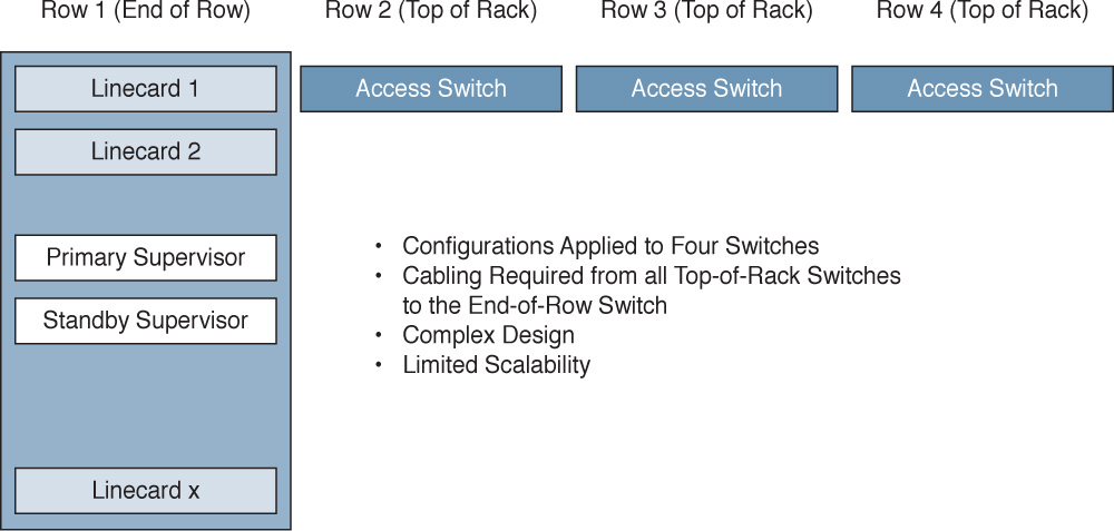
Today, many IT tasks are done manually on an ad hoc basis. For example, new business requirements are often brought to the IT team. As a member of either the storage, network, compute, or virtualization team, you then have to make a variety of decisions. See Figure 6-1. Do we have the capacity on hand today or do we need to order additional gear? What team needs to do their part first? How long will a project to meet these requirements take? What other projects am I currently working on that may impact my ability to accomplish this new project?
In addition to adding new projects and capabilities, you are often faced with having to make daily small adds and changes to your existing infrastructure. Some of these tasks are trivial. Others, such as adding a VLAN across a data center campus, can be fairly daunting in nature due to the high likelihood of human error or misconfiguration. Who hasn’t missed a switch configuration on a device or two during a change control at 2:00 a.m.?
The main goal of automation and orchestration is to allow you, the administrator or architect, to accomplish common tasks quickly and easily, the same way, time after time. Think of automation and orchestration as a very similar concept to a hopefully not too distant in the future concept. How great would it be if you could travel to a remote destination simply by hopping into your autonomous vehicle, inputting a destination address, and letting your vehicle drive you safely and reliably to your destination, giving you the chance to read, surf the web, talk on the phone, or simply attend to other tasks during the driving portion of your journey? All the while, you would have complete control to step in and take over if necessary to adjust your route, respond to an unforeseen situation, etc.
IT automation and orchestration are much like the previously described scenario. You have a mountain of tasks that you face daily in your job. Some are simple, one-step tasks. Others are compound tasks that are fairly order specific and complex. With automation and orchestration, much like the autonomous vehicle, you program in the tasks you want to accomplish and the vehicle takes care of the rest. In a cloud infrastructure, UCS Director is your vehicle. You program it to automate simple or complex IT tasks. You do this in conjunction with members of your organization from the other areas of infrastructure management discipline. The end results are great. You have taken a task or set of tasks that is manual in nature, time consuming, and prone to error and you’ve automated it with a few mouse clicks. More importantly, if there is a problem, you have the ability to roll back these changes immediately.
So to get your mind around the power of automation and orchestration, look at the list of daily/weekly tasks or projects that you face in IT and ask, “Is this something that I could automate? If I automated it, would it save time and allow me to work on more exciting projects?” If the answer to those questions is yes, congratulations, you are well on your way to bringing the wonderful benefits of a Cisco Powered cloud architecture to your organization!
Physical Switching
Founded in 1984, Cisco has a rich history in LAN switching. From the groundbreaking Catalyst series of switches that put Cisco on the map as an enterprise switching contender to the new Nexus and ACI products, Cisco’s expertise and history in switching have made it one of the most widely deployed switching products in most organizations today. For the purposes of this book, we will focus on the Nexus product line and Application Centric Infrastructure as products and concepts.
Nexus Series Switches
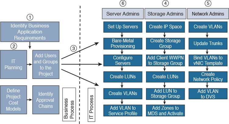
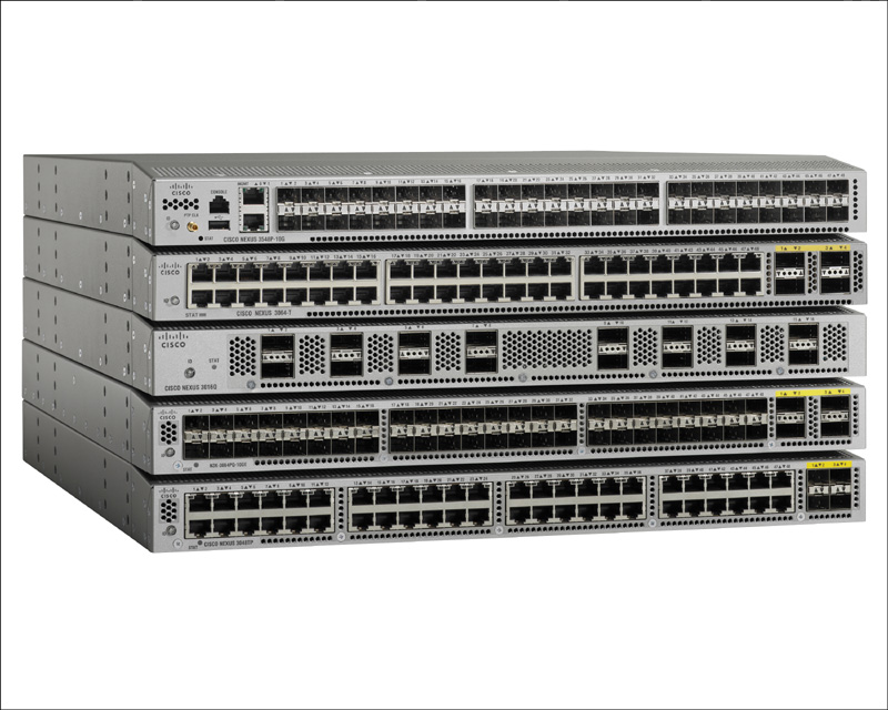
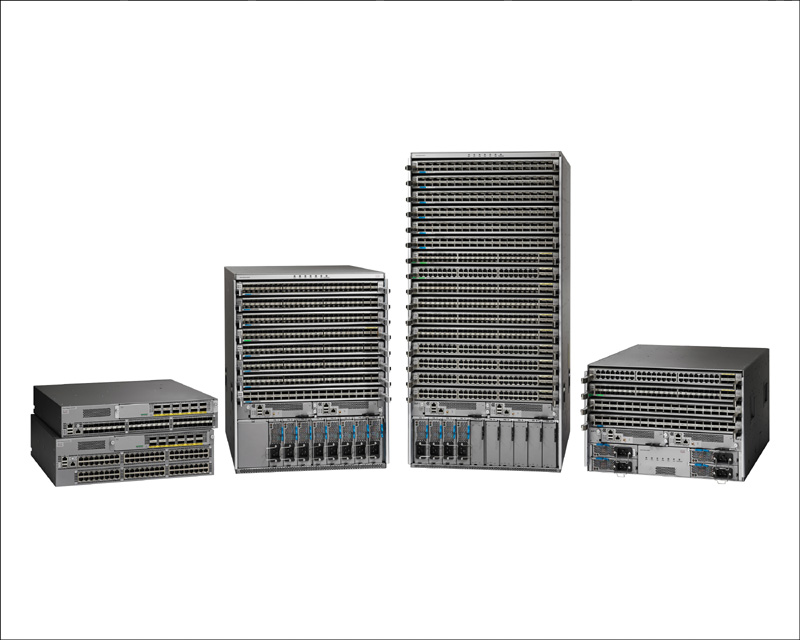
Starting with the Cisco Catalyst Series Switches as its current offering, Cisco set out to create its next generation of enterprise-class switches for the data center. Building on many of the concepts and the architecture of the extremely popular MDS (Multilayer Director Switch) Fibre Channel switch, Cisco introduced the Nexus Series Switches in 2008 with the introduction of the Nexus 7000. Since that time, Cisco has continued to round out the portfolio of offerings, covering a gamut of Ethernet connectivity options from 10 Mbps to 100 Gbps. Architecturally speaking, the Nexus product line runs Cisco NX-OS (Nexus Operating System), which was derived from SAN-OS, which powered Cisco’s Fibre Channel Series Switches previously. Whereas Ethernet products historically had moved megabits of traffic, the Cisco MDS had a proven track record of moving megabytes of Fibre Channel payloads through many organizations. The entire switch lineup can be seen in Figure 6-2.
Let’s take a look at the Cisco current switching portfolio.
The Nexus 2000 Series Fabric Extenders
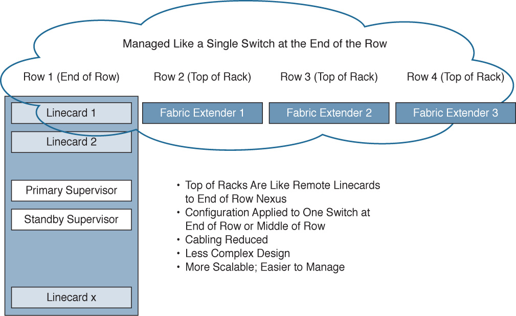
Marking a significant departure from previous products, the Cisco Nexus Fabric Extenders (FEX) don’t operate as a switch per se, but rather as a remote linecard to a parent switch.
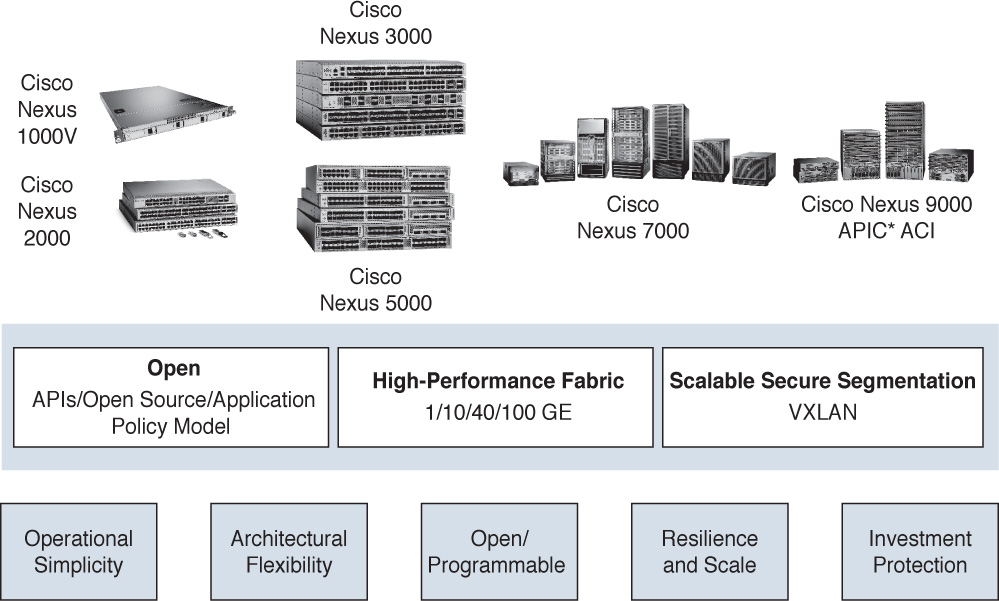
Prior to Fabric Extenders, management functions were typically all located within the confines of a single chassis. For example, switches were either large (modular) or small (fixed), but configuration happened on just that switch. In many designs, large switches were located in the middle of a data center row or in the end of a data center row and used to aggregate connections from multiple smaller switches. Configurations had to be applied to both the large switch and the smaller switches. See Figure 6-3.
This led to multiple challenges:
![]() Increase in cabling between switch rows
Increase in cabling between switch rows
![]() Increased requirements for firmware management
Increased requirements for firmware management
![]() Increased port and switch management
Increased port and switch management
![]() Less scalability
Less scalability
With the advent of the Nexus 2000 Fabric Extender, the Nexus 2000 device acts like a remote linecard to a central Nexus switch. All configuration for all ports gets applied to the single central switch. Also, multiple FEXs are supported per central Nexus switch. This leads to multiple benefits:
![]() Decrease in cabling between switches in rows
Decrease in cabling between switches in rows
![]() Decreased number of firmware management points (because FEX firmware is managed from the parent switch it is connected to)
Decreased number of firmware management points (because FEX firmware is managed from the parent switch it is connected to)
![]() Decreased port and switch management (one device as opposed to many devices)
Decreased port and switch management (one device as opposed to many devices)
![]() More scalability and density
More scalability and density
A Fabric Extender gets managed from its parent switch. This makes management much simpler, as shown in Figure 6-4.
As of the writing of this book, Cisco has the following FEX models available (see Figure 6-5):
![]() 100/1000 BASE-T: Nexus 2224TP, Nexus 2248TP (48 ports), and Nexus 2248TP-E (48 ports with extended buffers)
100/1000 BASE-T: Nexus 2224TP, Nexus 2248TP (48 ports), and Nexus 2248TP-E (48 ports with extended buffers)
![]() 10GBASE-T Fabric Extender: Nexus 2232TQ, 2348TQ, 2348TQ-E, 2232TM-E, and 2232TM
10GBASE-T Fabric Extender: Nexus 2232TQ, 2348TQ, 2348TQ-E, 2232TM-E, and 2232TM
![]() 10G SFP+ Fabric Extender: Nexus 2348UPQ, 2248PQ, and 2232PP
10G SFP+ Fabric Extender: Nexus 2348UPQ, 2248PQ, and 2232PP
Fabric Extenders can be mixed and matched in different types to create the connections and port densities required. Be sure to check with the configuration limits of each parent switch to ensure you don’t try to connect to many Fabric Extenders in a topology.
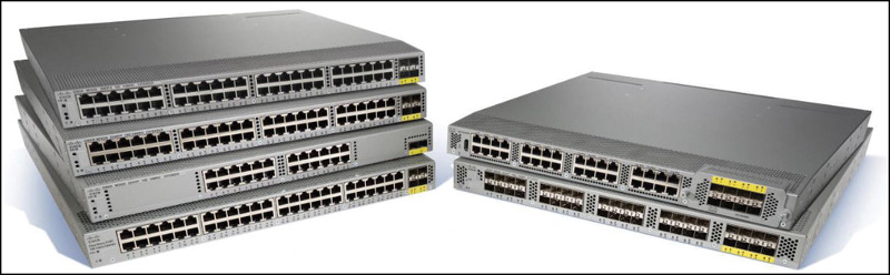
Cisco Nexus 3000 Series Switches
The Cisco Nexus 3000 Series Switches are designed for top-of-rack 1/10/25/40/50/100-GE connectivity with extremely low latencies and densities ranging from 24 to 128 ports. In addition, the Nexus 3000 Series supports Virtual Extensible LAN (VXLAN) for mobility and tenant isolation as well as accessibility via common scripting tools such as Python (see Figure 6-6).
Cisco Nexus 4000 Series Switches
Purpose built for the IBM BladeCenter chassis, the Nexus 4000 is a high-speed 10-GE switch that supports both 1/10-GE uplinks (see Figure 6-7).
Cisco Nexus 5000 Series Switches
Designed for low oversubscription of 1/10/40/100-GE top-of-rack access deployments or as a consolidation point for multiple Nexus 2000 Series Fabric Extenders, the Nexus 5000 Series of switches supports up to 128 fixed ports. However, with support for 24 to 48 total Fabric Extenders connected to the parent Nexus 5000 (depending on Nexus 5000 model), the total number of ports managed under a single Nexus 5000 can be extremely dense (see Figure 6-8).
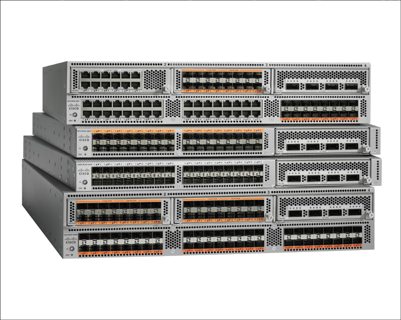
In addition, the Nexus 5000 line supports both Fibre Channel over Ethernet (FCoE) and Fibre Channel (FC) in 1/2/4/8/16-Gbps speeds (support and speed vary per switch model). As of the time of this writing, Cisco had six Nexus 5000 switches available: Nexus 5672UP, 5672UP-16G, 56128P, 5624Q, 5648Q, and 5696Q.
Cisco Nexus 6000 Series Switches
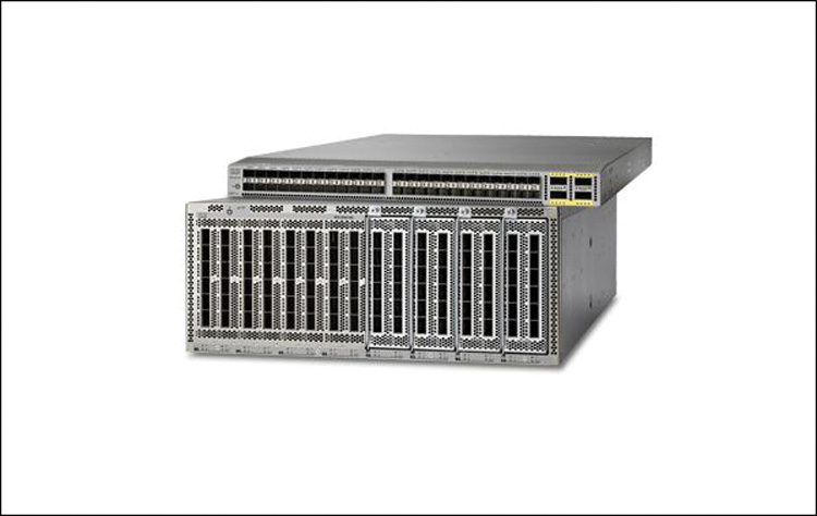
The Nexus 6000 lineup is designed for access- and space-constrained aggregation deployments, offering up to 384 ports of 10 GE or 96 ports of 40 GE and up to 160 unified ports supporting FCoE. It also supports Fabric Extenders. The chipset has been optimized and tuned for faster 10-GE and 40-GE traffic as opposed to Gigabit network flows (see Figure 6-9).
Cisco Nexus 7000 Series Switches
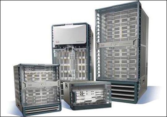
The Nexus 7000 switch was the first Nexus switch released in the product family in 2008. Ideal uses include data center access, aggregation, and core deployments. With the advent of virtual device contexts (VDC), the Nexus was the first switch in its class to allow switch virtualization and separation of services, allowing the collapsing (in many networks) of the access and aggregation layers, resulting in less complex, extremely scalable fabrics. With support for in-service software upgrades (ISSU), Fabric Extenders, and speed options from 1/20/40/100 GE, the Nexus 7000 is designed as a true enterprise-class workhorse for the most demanding networks (see Figure 6-10).
Cisco Nexus 9000 Series Switches
The Nexus 9000 Series Switch marks the next exciting evolution in the Cisco Nexus switching products. The Nexus 9000 can operate in two modes. For compatibility with existing networks, the switch can run in NX-OS standalone mode. This allows the Nexus 9000 to be introduced into existing fabrics in place of other platforms, such as the Nexus 5000 or Nexus 7000. However, for those with an eye on the next level of programmability and centralization of management in an enterprise network, the Nexus 9000 line can also be put into ACI mode, which will be described in detail in the next section on ACI. Offering speeds of 1/10/25/40/50/100 GE and a deep set of switch- and fabric-level software-defined programmable features, the Nexus 9000 line is helping Cisco usher in the area of software-defined networking (SDN). See Figure 6-11.
Cisco Cloud Programmability of Nexus Switches
Now the great news. Everything that you can accomplish as a network administrator using the command-line interface (CLI) or with scripts can also be accomplished in a Cisco Powered cloud deployment. Tasks that are time consuming, mundane, and prone to error can now be automated and orchestrated within UCS Director and executed predictably, repeatedly, and easily with UCS Director automation and orchestration tasks and workflows. Take just one simple scenario: adding a new VLAN to a large enterprise data center fabric. Imagine that your fabric has 60 switches. If you’re a network administrator, you know the tension and tedious nature of such a change as you ready a window (usually in the middle of the night on a weekend) to perform this operation over and over on each switch in the entire fabric. If you miss one, traffic can be dropped and problems can arise. With UCS Director, you could create an automation task that predictably and repeatedly rolls out a new VLAN across all switches in the data center campus, with literally just a few clicks. Unlike a network administrator relying on caffeine and pizza during a 2 a.m. change window, UCS Director will apply this to all the switches without missing a single switch. And if there is a problem? One-button rollback on some or all of the fabric is a core feature of UCS Director.
Introduction to Application Centric Infrastructure
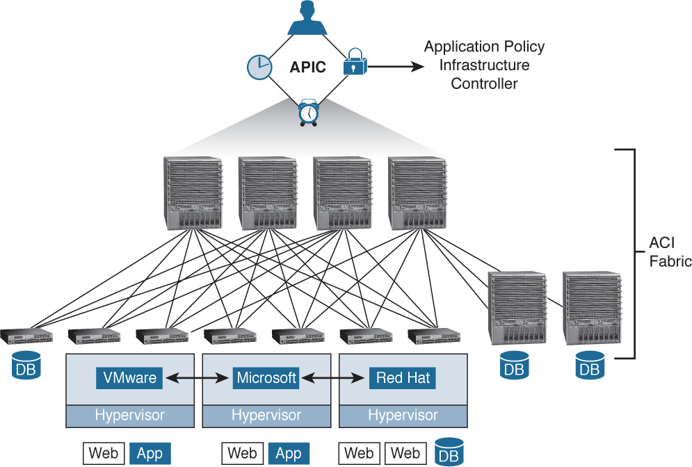
As mentioned previously in this chapter, Cisco recognizes that as fabrics become larger and as layers of virtualization via hypervisors (in compute) and virtualized network services (in the fabric) add more functionality, the previous method of configuring on a device-by-device basis is no longer feasible. If we recap the progression of administration, the Catalyst line of products required administrators to touch every single platform. The Nexus line, with Fabric Extenders, consolidated management onto fewer devices, while technologies such as VDCs allowed further consolidation still. However, as fabrics continue to grow in size and complexity, a better way is needed to program both virtual and physical network resources. Enter Application Centric Infrastructure (ACI). ACI allows the rapid deployment of applications onto networks with scale, security, and full visibility, whether those networks are physical or virtual (see Figure 6-12).
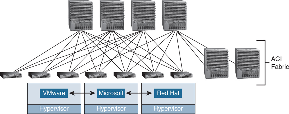
The concept behind ACI is simple yet powerful. Using a set of redundant Application Policy Infrastructure Controllers (APICs), you can define and apply network policy in a single location to literally hundreds or thousands of devices all across your network. Once defined at the APIC level, that policy can easily be deployed across a variety of physical (bare-metal) network ports as well as ports within a variety of hypervisors such as VMware ESX, Microsoft Hyper-V, and Red Hat KVM (see Figure 6-13).
These policies are defined as high-level application connectivity/security needs, but instead of tightly coupling them with a large network the way you previously did on a per physical or virtual port basis, these policies can now be abstracted from the complicated details of a large network topology and then easily applied where needed.
Application Network Profiles and How They Work
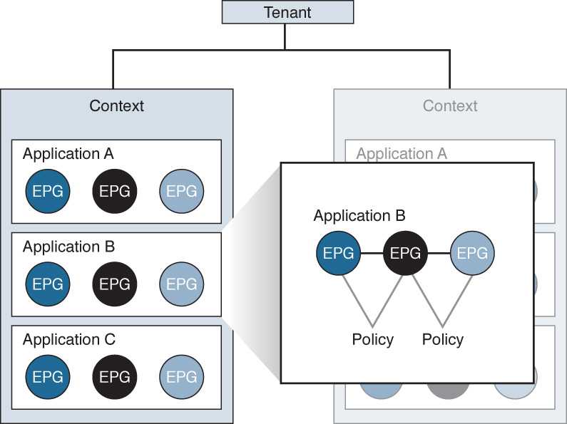
At the top level, ACI is an object model built on a concept of one or more tenants. Tenants in the ACI model can include something like a particular department within your organization, a business unit, an application group, etc. A service provider hosting multiple customers may have dozens of tenants, whereas your organization may simply have one tenant, the name of your company.
Underneath the concept of the tenant in ACI there exists a context. A context can be thought of as a set of rules for separate IP spaces or virtual routing and forwarding instances. A context is simply a further way to segment and separate forwarding requirements within a tenant. A tenant can also, hierarchically, have multiple contexts.
Within the context you will find a series of objects that define actual applications on the network called endpoints (EPs) and endpoint groups (EPGs) as well as the policies that define the relationships between the EPs and EPGs. These policies are not only access control lists (ACL), but also inbound and outbound filters, quality of service (QoS) settings, marking rules, redirection rules, and other settings that define specific L4–L7 interactions between the EPGs (see Figure 6-14).
Now that we have a frame of reference for how objects are referenced within an ACI environment, we can look at how application network profiles (ANP) work. An ANP can be used to define permissible (or denied) interactions between EPGs. For example, if we imagine a three-tier application of Web, App, and Database, each tier would exist as an EPG and potentially contain endpoints. We will discuss a theoretical application that has five web servers, two app servers, and one database server (see Figure 6-15):
![]() Web EPG, consisting of five web EPs
Web EPG, consisting of five web EPs
![]() Application EPG, consisting of two app EPs
Application EPG, consisting of two app EPs
![]() Database EPG, consisting of one database EPs
Database EPG, consisting of one database EPs
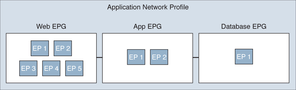
Once you have an idea of how you need the application tiers to interact, you would create the EPGs per tier, then create the policies to define connectivity between EPGs (such as log, mark, redirect, permit, deny, copy, etc.), and then create the connection between the EPGs. These connections between EPGs are known as contracts.
The ANP therefore is composed of a contract or contracts between multiple EPGs containing one or more EPs per EPG.
As your organization transitions from traditional NX-OS and CLI-based administration to an ACI-based network, UCS Director once again can provide a tremendous amount of value to you as many of the ACI- and APIC-related functions that you would perform on a daily basis are available within UCS Director as tasks that can be chained together into workflows to help create self-service capabilities for an ACI-enabled network.
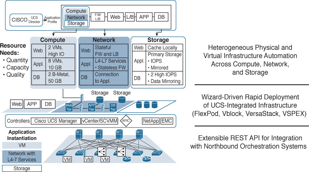
Infrastructure Automation and UCS Director
Once the main components of a Cisco Powered cloud (Prime Service Catalog and UCS Director) have been implemented, they need to connect to various components in your data center to do automation and orchestration (see Figure 6-16). Some of the devices that can be attached to UCS Director for automation and orchestration include:
![]() Physical Ethernet switches such as those in the Cisco Nexus family and Catalyst family as well as various third-party switches
Physical Ethernet switches such as those in the Cisco Nexus family and Catalyst family as well as various third-party switches
![]() Virtual Ethernet switches such as the Cisco Nexus 1000V or Application Virtual Switch (AVS), as well as various third-party virtual switches, including the VMware Distributed Virtual Switch (DVS)
Virtual Ethernet switches such as the Cisco Nexus 1000V or Application Virtual Switch (AVS), as well as various third-party virtual switches, including the VMware Distributed Virtual Switch (DVS)
![]() Nexus 9000 APIC, which enables the UCS Director administrator to issue automation and orchestration commands against a Nexus 9000 Application Programmable Interrupt Controller
Nexus 9000 APIC, which enables the UCS Director administrator to issue automation and orchestration commands against a Nexus 9000 Application Programmable Interrupt Controller
![]() Other Ethernet network physical and virtual appliances such as Cisco VACS, Cisco CSR 1000V, ASA 1000V, and third-party physical and virtual networking appliances such as an F5 BIG-IP load balancer
Other Ethernet network physical and virtual appliances such as Cisco VACS, Cisco CSR 1000V, ASA 1000V, and third-party physical and virtual networking appliances such as an F5 BIG-IP load balancer
![]() Fibre Channel switches including Cisco MDS and Brocade Fibre Channel switches
Fibre Channel switches including Cisco MDS and Brocade Fibre Channel switches
![]() Fibre Channel and IP-based storage arrays, including many popular arrays from Pure Storage, EMC, NetApp, IBM, and others
Fibre Channel and IP-based storage arrays, including many popular arrays from Pure Storage, EMC, NetApp, IBM, and others
![]() Compute platforms including support for Cisco UCS Central, Cisco UCS Manager, Standalone UCS C-Series rackmount servers (utilizing Cisco Integrated Management Controller, or CIMC), as well as third-party servers such as those from HP, Dell, and IBM through standards like IP Management Interface (IPMI)
Compute platforms including support for Cisco UCS Central, Cisco UCS Manager, Standalone UCS C-Series rackmount servers (utilizing Cisco Integrated Management Controller, or CIMC), as well as third-party servers such as those from HP, Dell, and IBM through standards like IP Management Interface (IPMI)
Virtual Switching
According to Moore’s law, processor transistor capacity approximately doubles on average every two years. This hypothesis was first posited in 1965 by Gordon Moore, one of Intel’s cofounders. To date, it has largely held true. In the mid-to-late 1990s, realizing that most bare-metal operating systems and applications were consuming only a fraction of available CPU and memory capacity, vendors started to introduce hypervisors in the server space to help more efficiently use the excess memory and CPU capacity that had been created as processors continued to become faster, denser, and more capable over time.
Before servers were virtualized, life was much simpler for network and server administrators. One (physical) server usually ran one application and consumed one (physical) network port. With the advent of the hypervisor, IT administrators also entered a new chapter in their careers, where multiple servers and applications, each with potentially different connectivity requirements, started to intermingle on a single physical host with a hypervisor installed, such as VMware ESX. With these changing requirements, the days of having a single host with a single application connected to a single switch port were gone. IT simply needed more flexibility. This brings us to the advent of the virtual switch.
Virtual Switching Overview
In the simplest terms, a virtual switch acts much like a physical switch, only it’s made in software as opposed to being a physical/tangible switch that you could pick up and hold with your hands. A virtual switch is software that sits within a hypervisor on a physical host to provide VM-to-VM communication within that single host and also VM communication with other endpoints (such as a user running a query from their desktop against a database running on a virtual server) elsewhere on the network. In addition, virtual switches rely on the generic capabilities of the x86 processor and consume some CPU and memory overhead from that processor (that is therefore not available to the rest of the compute functions in the cluster). By contrast, physical switches, such as the Cisco Nexus 9000, use purpose-built ASICs in the hardware that are designed specifically for high-speed switching and packet processing.
As virtualization continued to grow in popularity, the industry started moving beyond the capabilities of a single virtual switch on a single physical host. As multiple physical hosts were joined together into more powerful clusters, the concept of having a single virtual switch tied to a single virtual host was no longer practical because every time a new hypervisor-based host was added to the network, another virtual switch had to be configured.
This led to the advent of the distributed virtual switch (DVS). A DVS sits within the hypervisor of multiple physical hosts, providing distributed networking services between multiple hosts in a cluster. As clusters have grown in size from 2 hosts to now up to 32 or more hosts, having a DVS is no longer a luxury; it is a necessity.
Cisco has two offerings in the DVS category: Nexus 1000V and the Application Virtual Switch. Let’s take a quick look at each.
Nexus 1000V
The Cisco Nexus 1000V was created with the main Nexus product family during the advent of the Nexus 2000/5000/7000 product line and is geared mainly for traditional Nexus networking environments. It works very much like a virtual version of a Nexus 5000 or Nexus 7000 (with Nexus 2000 Fabric Extenders) architecture.
In the physical switching world, the main Nexus 5000 device acts as the management and configuration plane for building the switch configuration and services. Ports on a Nexus 2000–connected FEX receive their port configuration from the Nexus 5000.
A Nexus 1000V architecture (see Figure 6-17) typically has three main components:
![]() A Virtual Supervisor Module (VSM)
A Virtual Supervisor Module (VSM)
![]() A Virtual Ethernet Module (VEM)
A Virtual Ethernet Module (VEM)
![]() Integration with a virtual management console such as VMware Virtual Center or Microsoft SCVMM
Integration with a virtual management console such as VMware Virtual Center or Microsoft SCVMM
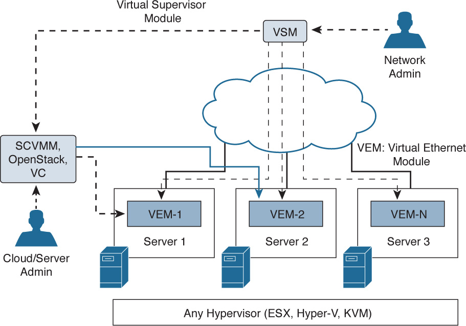
In this model, you log in (usually via SSH/CLI) to the VSM and create a port configuration(s) for a virtual machine (called a virtual Ethernet, or vEthernet, interface). Those configurations then get pushed out from the VSM to VEMs that should receive that configuration.
The Nexus 1000V is fully integrated with UCS Director and comes with many prebuilt tasks required for administering and managing the Nexus 1000V within automation tasks.
AVS Architecture and Components
With the advent of the Cisco Nexus 9000 Series Switches, the Application Policy Infrastructure Controller (APIC), and the Application Centric Infrastructure (ACI), you no longer have to go to separate physical and virtual devices to apply network policy and configuration. In a Nexus 9000 environment in ACI mode, configuration happens one time at the APIC level and that configuration can then be applied to physical network ports as well as to virtual network ports using the Application Virtual Switch (AVS).
Similar in concept, the use case for AVS differs from Nexus 1000V as highlighted in Table 6-2.
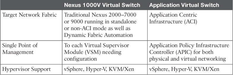
So while materially similar, the AVS is targeted for ACI-enabled networks, whereas the Nexus 1000V is the right tool of choice for non-ACI-enabled networks.
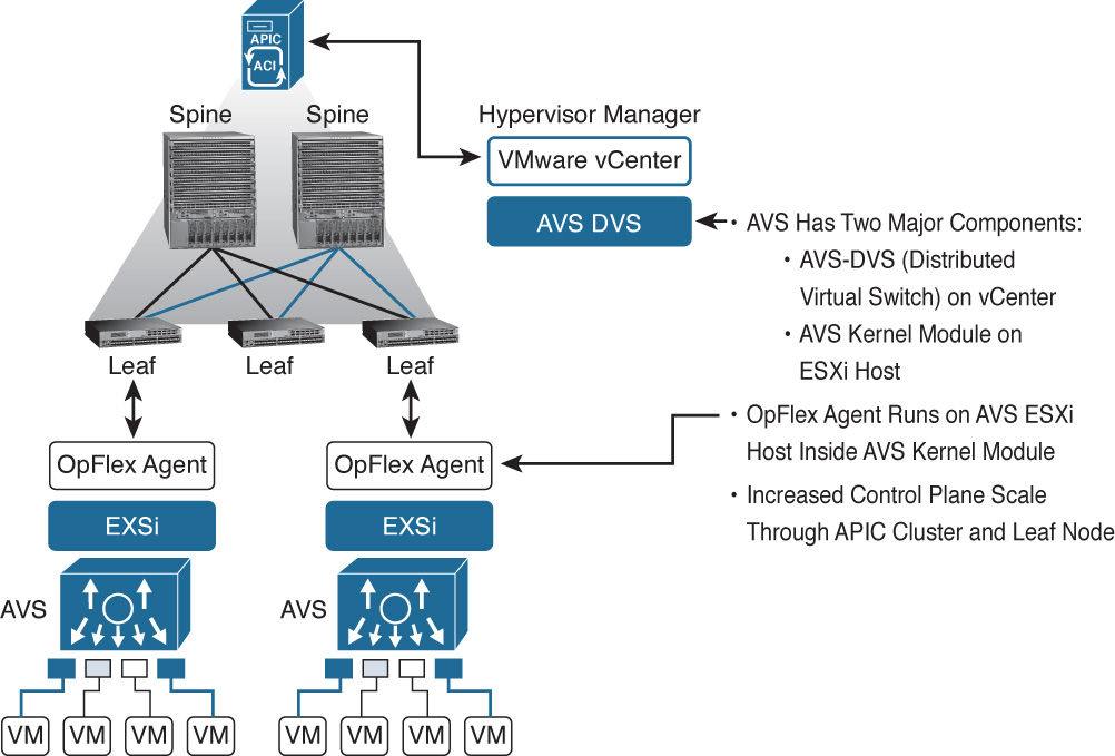
Architecturally, AVS has two major components (see Figure 6-18):
![]() The AVS-DVS (Distributed Virtual Switch) on vCenter
The AVS-DVS (Distributed Virtual Switch) on vCenter
![]() An AVS kernel module on each ESXi host that is ACI enabled
An AVS kernel module on each ESXi host that is ACI enabled
Virtual Application Cloud Segmentation (VACS)
The entire purpose of building a Cisco Powered cloud is so that you can quickly provision complete Infrastructure as a Service (IaaS) and Platform as a Service (PaaS) offerings for your internal users. In the previous section, we saw how ACI using the AVS with Nexus 9000 and APIC can offer rich L4–L7 network services for virtual machines.
In situations where ACI may not yet be deployed but the need still exists for rich networking services to be deployed alongside virtual machines, Cisco Virtual Application Cloud Segmentation (VACS) can be a great fit (see Figure 6-19). VACS offers the following:
![]() Easy installation within UCS Director for automated provisioning and orchestration
Easy installation within UCS Director for automated provisioning and orchestration
![]() Load balancing
Load balancing
![]() Routing (using the Cisco CSR 1000V)
Routing (using the Cisco CSR 1000V)
![]() Edge firewall capability (using Cisco CSR 1000V)
Edge firewall capability (using Cisco CSR 1000V)
![]() Zone-based firewall (using Cisco Virtual Security Gateway)
Zone-based firewall (using Cisco Virtual Security Gateway)
![]() Virtual fabric (using Cisco Nexus 1000V)
Virtual fabric (using Cisco Nexus 1000V)
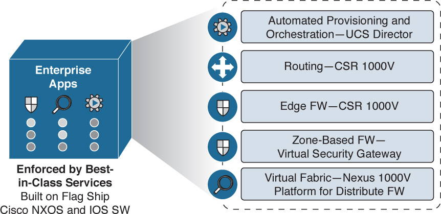
With deep integration into UCS Director, this allows secure segmentation and rapid deployment of applications in virtual data centers by helping to consolidate physical assets onto a single infrastructure that can then be virtualized to provide deep security and network services. In addition, VACS brings all the products previously mentioned into a single unified license, making it easy to deploy, license, and manage all the components included within VACS.
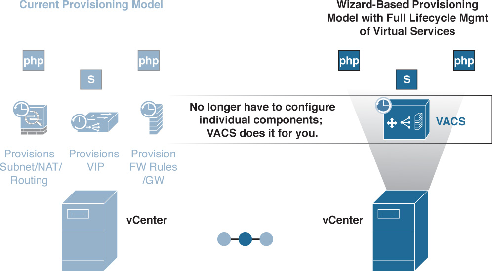
When you are allocating L4–L7 network services physically for virtual machines, service times typically increase as complexity increases and many points of management have to be configured in a solution. For example, if a particular virtualized server and application are using network load-balancing services as well as firewall services that are physical, you would be required to not only procure, rack, stack, and configure those physical devices, but also create configurations for your virtual services on each independent device (see Figure 6-20).
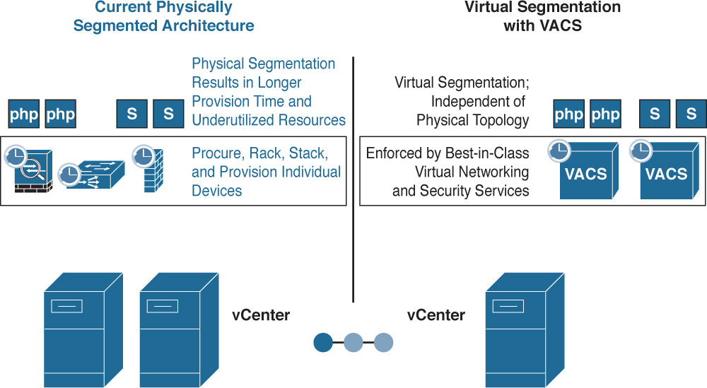
Alternatively, leveraging virtual segmentation with VACS allows single-click installation within the Cisco Powered cloud framework (within UCS Director) and allows you to focus on one place to go to set up best-in-class virtual networking and security services. This is accomplished easily with wizards (see Figure 6-21).
VACS Containers
Within VACS, there is a concept known as a container. Containers are defined by the following:
![]() Virtual network and security services templates for application workloads
Virtual network and security services templates for application workloads
![]() Topology configurations designed for logical secure isolation and compliance
Topology configurations designed for logical secure isolation and compliance
![]() Exposed through the UCS Director GUI to allow rapid and consistent provisioning of secure applications and rich L4–L7 services
Exposed through the UCS Director GUI to allow rapid and consistent provisioning of secure applications and rich L4–L7 services
Containers can be thought of as situation-specific templates that govern connectivity, security, and services in a multitiered virtualized application environment. Again, using our previous example of a three-tier application consisting of a web tier, an application tier, and a database tier, let’s look at two different types of VACS containers, the VACS 3-tier internal container template and the 3-tier external container template (see Figure 6-22). A third example would be a VACS custom container template, which won’t be covered here.
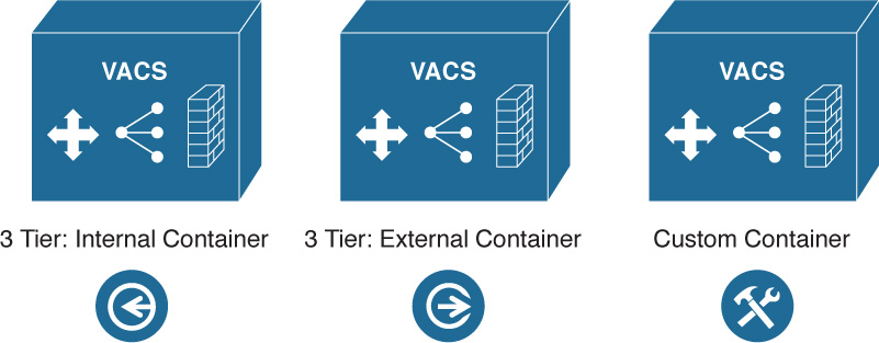
VACS 3-Tier Internal Container Template
Let’s assume the business has a requirement for you to deploy a three-tier application internally. They want to ensure that only authorized users, authenticated from the web tier, can access this application. If you were to build this manually, it would require (at a minimum):
![]() Deploying virtual web servers and configuring the application layers of the VMs
Deploying virtual web servers and configuring the application layers of the VMs
![]() Deploying virtual application servers and configuring the application layers of those VMs
Deploying virtual application servers and configuring the application layers of those VMs
![]() Deploying virtual database servers and configuring the application layers of those VMs
Deploying virtual database servers and configuring the application layers of those VMs
![]() Deploying a physical firewall and configuration application connectivity policies between the web tier, app tier, and database tier of the preceding three virtual systems
Deploying a physical firewall and configuration application connectivity policies between the web tier, app tier, and database tier of the preceding three virtual systems
![]() Determining the best way to route traffic securely through each application tier into the firewall and applying the appropriate firewall rules to each step of the application
Determining the best way to route traffic securely through each application tier into the firewall and applying the appropriate firewall rules to each step of the application
![]() Inserting load-balancing services in front of the web tier to provide proper load balancing
Inserting load-balancing services in front of the web tier to provide proper load balancing
This would be quite a bit of configuration, just to get that one instance of the three-tier application up. Whenever another application owner came along with the same request, you would find yourself completing the same steps yet again (and again as more application requirements came to you from the business side of your organization).
Using one of the defined VACS 3-tier internal container templates, you could simply click the container template and create a new container for the application. All the proper rules for firewalling, load balancing, and routing would be predefined within the 3-tier internal container template via policy (see Figure 6-23).
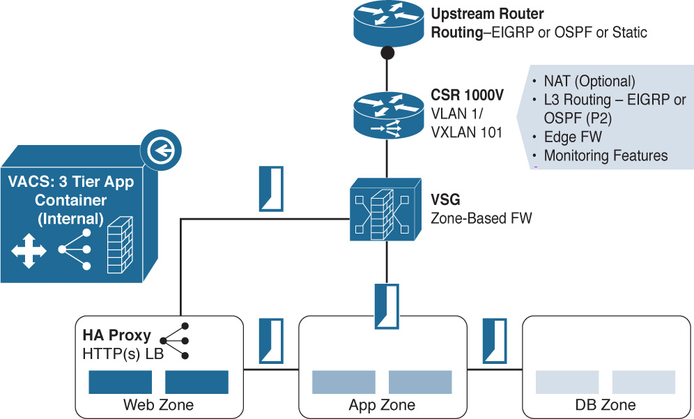
As you can see, given that security requirements are not quite as tight for this internal application, connectivity from the Virtual Security Gateway (VSG) zone-based firewall flows toward the web zone’s load balancer and, from there, to the app zone and DB zone. Now you have a template that you can predictably and repeatedly invoke whenever a new three-tier application requirement comes your way.
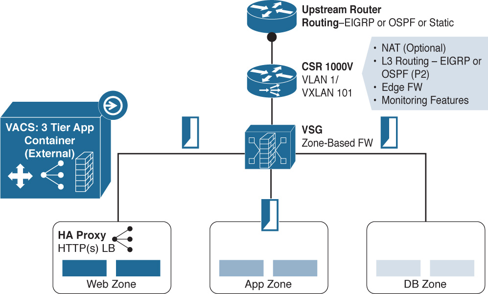
VACS 3-Tier External Container Template
If the application requires greater security and increased firewall use for security or compliance purposes, the 3-Tier External Container Template, shown in Figure 6-24, provides additional security because the firewall is in the communication path between all layers of the three-tier application.
As previously mentioned, it is also very straightforward to create custom VACS Container Templates for one-tier, two-tier, three-tier, or n-tier applications and define communication, security, load balancing, and other requirements between the different zones in the VACS custom container template. Saving this template will then give you a quick way to consistently and predictably deploy similar application services should the need arise in the future.
Building a VACS Container with Gateway of Choice
Often, existing standards in the environment may dictate using an existing technology as the default gateway for a VACS container. Within VACS, there is an option and the flexibility to combine both VACS services with standard deployed services in the environment.
For example, as shown in Figure 6-25, VACS can use
![]() The built-in virtual gateway, the CSR 1000V
The built-in virtual gateway, the CSR 1000V
![]() A physical gateway, such as one from Palo Alto Networks or Checkpoint, or a Cisco ASA
A physical gateway, such as one from Palo Alto Networks or Checkpoint, or a Cisco ASA
![]() Another virtual gateway, such as the Cisco Adaptive Security Virtual Appliance (ASAv), Juniper Virtual Gateway (vGW), or Virtual Palo Alto Networks (vPAN)
Another virtual gateway, such as the Cisco Adaptive Security Virtual Appliance (ASAv), Juniper Virtual Gateway (vGW), or Virtual Palo Alto Networks (vPAN)
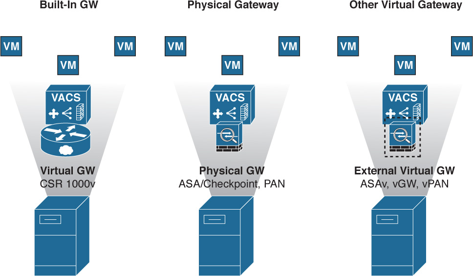
When you’re deploying VACS and choosing the gateway of choice, it’s important to know how to operationalize this choice. You will need the gateway IP and you will get it installed as part of the VACS report after you spin up a VACS container from a template. You can use this information to program in any device (physical or virtual) of your choice as mentioned in the previous list.
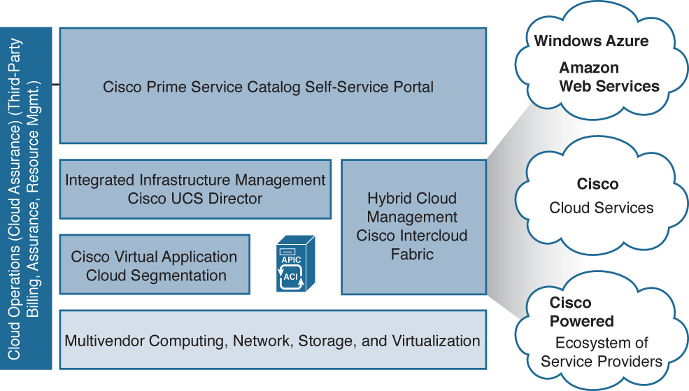
Intercloud Fabric
As we’ve looked at the core components of a Cisco Powered cloud, we’ve focused a lot of discussion on the components that exist on premises. However, many IT workloads are also taking advantage of public cloud offerings such as Microsoft Azure, Amazon Web Services, or other Cisco Powered cloud ecosystem providers (see Figure 6-26).
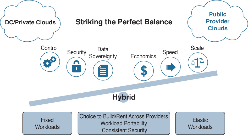
Therefore, any good cloud solution should not only address multiple clouds (on premises and public as well as hybrid), but also different capabilities for configuration of an on-premises or public cloud infrastructure across a wide variety of public cloud services. Such is the role of Intercloud Fabric.
As with any strategy, the decision on where to host IT infrastructure (on premises or in the public cloud) boils down to a variety of factors. Some of them may be regulatory (such as needs around data sovereignty), or economic (workloads that are highly elastic or only needed during a short period of time each month/quarter/year). Figure 6-27 shows some of the criteria that go into choosing where to host a particular workload in a hybrid cloud deployment.
Why Hybrid
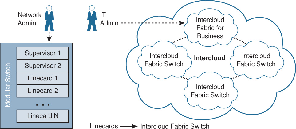
Intercloud Fabric uses a similar architecture to that of distributed virtual switches such as the Nexus 1000V, as discussed earlier in the chapter. In a modular switch such as a Nexus 7000, the supervisors and linecards all exist in one modular chassis (unless using “distributed linecards” such as a Fabric Extender). In Intercloud Fabric, you interact with the on-premises component of the virtual “supervisor” while linecards are distributed throughout various public cloud services (see Figure 6-28).
This gives you the ability to address public cloud resources in much the same way operationally as you do your internal private cloud resources. Hybrid really provides the best of both worlds. Host-critical or latency-sensitive applications and virtual machines on premises “burst or flex” less important (or seasonal) workloads out into the public cloud. This provides many benefits:
![]() Layer 2 IP addressing used within your organization can be securely extended into various public cloud spaces, allowing VMs to use similar IP addresses as they would use internally.
Layer 2 IP addressing used within your organization can be securely extended into various public cloud spaces, allowing VMs to use similar IP addresses as they would use internally.
![]() It enables integration with Prime Service Catalog to allow IT to become the broker for public cloud services. Today your IT team may be largely unaware of the extent and use of public cloud services. With Intercloud Fabric, you become aware of public cloud projects and can quickly and securely offer these services to your internal consumers of IT.
It enables integration with Prime Service Catalog to allow IT to become the broker for public cloud services. Today your IT team may be largely unaware of the extent and use of public cloud services. With Intercloud Fabric, you become aware of public cloud projects and can quickly and securely offer these services to your internal consumers of IT.
![]() Security and policy can be set within the organization and applied/enforced into public cloud services.
Security and policy can be set within the organization and applied/enforced into public cloud services.
![]() Virtual machine portability and the ability to move virtual machines from on premises to public cloud providers and back.
Virtual machine portability and the ability to move virtual machines from on premises to public cloud providers and back.
![]() Automation, including complete VM lifecycle management, automated operations, and an open API for easy programmatic access.
Automation, including complete VM lifecycle management, automated operations, and an open API for easy programmatic access.
Let’s look at how this is accomplished.
How It Works
Architecturally, Intercloud Fabric has two different products that are used to address both the on-premises and public portions of the cloud.
Intercloud Fabric for Business
Intercloud Fabric for Business is the enterprise portion of the solution that you install on premises. It allows you to transparently extend your internal VLANs and Layer 2 segments securely from within your private cloud infrastructure out to public cloud services while keeping the same level of security and policy across both the private and public environments. It is composed of two different components:
![]() Cisco Intercloud Fabric Director
Cisco Intercloud Fabric Director
![]() Cisco Intercloud Fabric Secure Extender
Cisco Intercloud Fabric Secure Extender
Cisco Intercloud Fabric Director is used to provide workload management in your hybrid cloud environment by allowing you to not only create, manage, and extend network services between private and public clouds, but also offer policy and a self-service IT portal that makes it easy for you to define and provide services (such as virtual machines and the secure network policies associated with them) to your end users. This allows you to publish catalogs to your internal end users that will rapidly allow them to request, for instance, different virtual machine types in different public cloud providers.
Intercloud Fabric for Providers
This is the portion of the architecture that exists in provider cloud environments and provides the “receiving end” of the end-to-end components that stretch from your private on-premises cloud out into a public cloud provider. Getting into more detail on Intercloud Fabric for Providers is beyond the scope of this book, but you can easily research it in greater detail on Cisco.com.
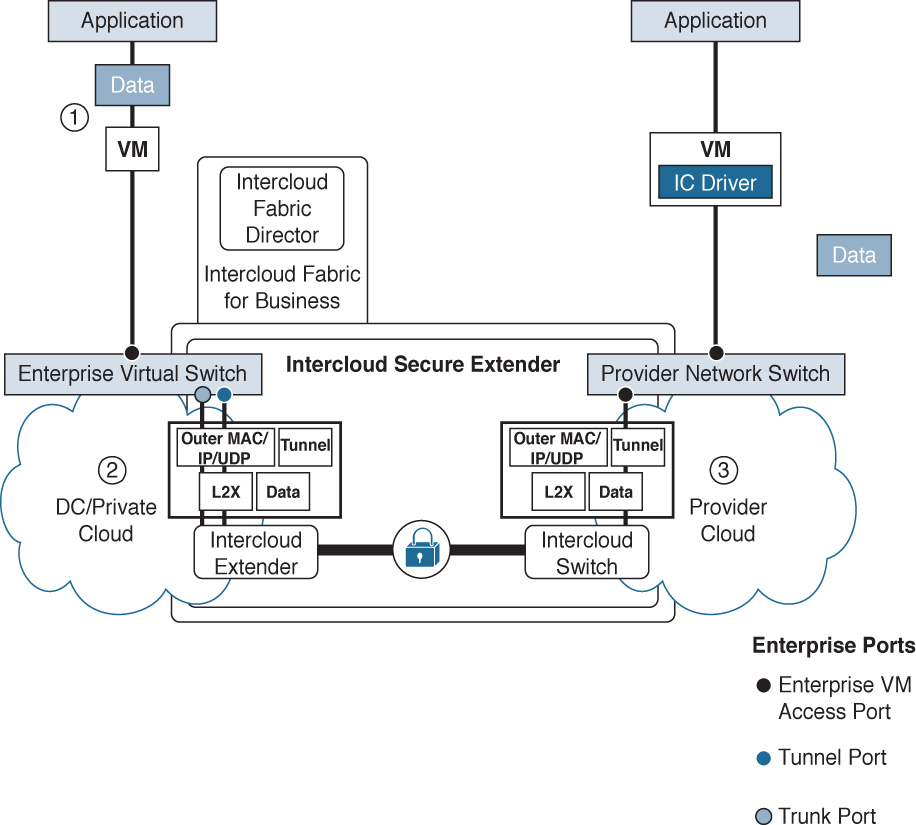
Secure Network Extender
To extend portions of your private, on-premises cloud infrastructure out into a public cloud provider, you use the Intercloud Fabric Secure Extender. This provides an AES 256-bit encrypted tunnel between your data center and the public cloud, securely extending VLANs and Layer 2 spaces out into the public provider cloud. This allows policy, security, and connectivity to be defined within the DC/private cloud infrastructure (as endpoints) while being enforced on any virtual machines created in the public cloud through Intercloud Fabric Director (see Figure 6-29).
Secure Network Extension to the Public Cloud
Once you have secure tunnels connected between your private data center cloud and certain public cloud providers, you will realize many benefits. Having a secure network extension to the public cloud with Intercloud Fabric can help with the following challenges in your organization:
![]() Shadow IT: In many cases you don’t have visibility into public cloud resources being used by your organization.
Shadow IT: In many cases you don’t have visibility into public cloud resources being used by your organization.
![]() Compliance: Your job of securing access to different resources gets obfuscated once workloads move from your purview/control on premises to public cloud infrastructures.
Compliance: Your job of securing access to different resources gets obfuscated once workloads move from your purview/control on premises to public cloud infrastructures.
![]() Different IP/VLAN/Layer 2 address ranges: If, for example, an application is rapidly prototyped externally in a public cloud space, how would you easily bring it back on premises to move it from dev/test into production?
Different IP/VLAN/Layer 2 address ranges: If, for example, an application is rapidly prototyped externally in a public cloud space, how would you easily bring it back on premises to move it from dev/test into production?
Intercloud Fabric solves these and many other challenges you face in interacting with public cloud services. For example, Intercloud Fabric provides these solutions (see Figure 6-30):
![]() Secure Layer 2 network extension from on premises to dozens of public cloud providers
Secure Layer 2 network extension from on premises to dozens of public cloud providers
![]() Automated workload mobility to and from public cloud providers
Automated workload mobility to and from public cloud providers
![]() The ability for you to manage both on-premises and public cloud resources through a single management console
The ability for you to manage both on-premises and public cloud resources through a single management console
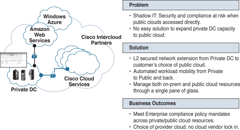
In the end, this helps you meet enterprise compliance more easily because secure networking and policy get extended into a myriad of public cloud offerings. Additionally, this gives you and your organization freedom of public cloud provider choice and prevents cloud provider vendor lock-in.
Exam Preparation Tasks
As mentioned in the section “How to Use This Book” in the Introduction, you have a couple of choices for exam preparation: the exercises here, Chapter 15, “Final Preparation,” and the exam simulation questions on the Pearson IT Certification Practice Test.
Review All Key Topics
Review the most important topics in this chapter, noted with the Key Topics icon in the outer margin of the page. Table 6-3 lists a reference of these key topics and the page number on which each is found.
Table 6-3 Key Topics for Chapter 6
Define Key Terms
Define the following key terms from this chapter and check your answers in the glossary:
Application Policy Infrastructure Controller (APIC)
Application Centric Infrastructure (ACI)
Fibre Channel over Ethernet (FCoE)
Multilayer Director Switch (MDS)
in-service software upgrade (ISSU)
Virtual Supervisor Module (VSM)
Application Virtual Switch (AVS)
Virtual Application Cloud Segmentation (VACS)
software-defined networking (SDN)
Virtual Security Gateway (VSG)