
Chapter 9. Automating Cloud Infrastructure with UCS Director
This chapter covers the following exam topics:
3.0 Cloud Provisioning
3.3 Deploy preconfigured templates and make minor changes to the service catalog offerings that do not affect workflows or services
3.3.a Describe the deployment of templates: storage, compute, network, and virtualization
3.3.b Describe differences between the templates
3.3.c Describe the need to convert between templates
There are many reasons to decide to implement a private cloud for your enterprise. The main reason should be to better enable your users to consume and manage infrastructure resources (compute, storage, network, etc.) by providing them the capability to discover services, order services, and manage their own consumption with little to no manual interaction with the IT team. Before you can provide users with this capability, you need to develop the services that will be made available. To do this, you need a comprehensive understanding of how to deliver the infrastructure that will back these services. Policies describing the consumption of compute, network, and storage resources need to be developed. And, automation workflows to deploy the standard configurations need to be built and tested.
Cisco UCS Director provides a platform for infrastructure management and automation designed for IT infrastructure teams to work together to easily build policies for standard infrastructure offerings. The virtual data centers and workflows you will build in UCS Director provide the foundation for users to begin ordering and managing their own resources within the cloud.
“Do I Know This Already?” Quiz
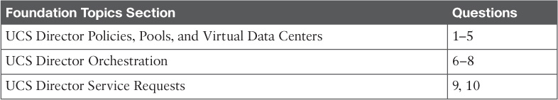
The “Do I Know This Already?” quiz allows you to assess whether you should read this entire chapter thoroughly or jump to the “Exam Preparation Tasks” section. If you are in doubt about your answers to these questions or your own assessment of your knowledge of the topics, read the entire chapter. Table 9-1 lists the major headings in this chapter and their corresponding “Do I Know This Already?” quiz questions. You can find the answers in Appendix A, “Answers to the ‘Do I Know This Already?’ Quizzes.”
Caution
The goal of self-assessment is to gauge your mastery of the topics in this chapter. If you do not know the answer to a question or are only partially sure of the answer, you should mark that question as wrong for purposes of the self-assessment. Giving yourself credit for an answer you correctly guess skews your self-assessment results and might provide you with a false sense of security.
1. How many groups will be assigned ownership of a virtual data center?
a. One group
b. One or more groups
c. No groups, because virtual data centers are assigned to users
d. All groups share the same virtual data center assignments
2. Within what construct within UCS Director will you configure the policies that determine how a new virtual machine will be deployed into a cloud?
a. Virtual private cloud (vPC)
b. Virtual pod (vPod)
c. Virtual data center (vDC)
d. Virtual tenant (vTenant)
3. Which policy determines how elements such as hostname, domain membership, DNS settings, and time zone are configured?
a. Service Delivery Policy
b. Computing Policy
c. Guest Customization Policy
d. System Policy
4. Which of the following can be configured within UCS Director as part of the integrated IP address management capabilities?
a. Static IP pools
b. VLAN pools
c. IP subnet pools
d. All of the above
e. None of the above
5. When creating a new service profile through UCS Director, which physical infrastructure policies and templates must be configured within UCS Director itself? (Choose three.)
a. vNIC template
b. UCS Network Policy
c. UCS Storage Policy
d. UCS Bios Policy
e. UCS Boot Policy
6. What does the Workflow Property “Mark as Compound Task” indicate?
a. That this workflow is made up of child workflows
b. That this workflow will be leveraged in other workflows
c. That this workflow leverages external libraries and features
d. That this workflow will target a specific virtual machine
7. How do you add a new task to a workflow?
a. Right-click in the Workflow Designer design area and choose New
b. Drag from the Available Tasks list
c. Double-click a task in the Available Tasks list
d. Any of the above
8. With what type of task can you ask an external user to provide an input value during workflow execution?
a. User Approval Task
b. Get Input Task
c. Custom Approval Task
d. Query User Task
9. Which tab(s) of a service request can an end user view? (Choose all that apply.)
a. Status
b. Log
c. Objects Created/Modified
d. Inputs/Outputs
10. True or False. In order to use the Rollback capability of UCS Director, you must first build a workflow that acts as an Undo for the action you wish to roll back.
a. True
b. False
Foundation Topics
UCS Director Policies, Pools, and Virtual Data Centers
To dynamically deliver infrastructure resources to users, your team of cloud architects and engineers must configure policies and workflows that reflect the intended standards for your enterprise. Several decisions must be made during provisioning, such as
![]() What hypervisor host and data store to instantiate new VMs on
What hypervisor host and data store to instantiate new VMs on
![]() If and how to provide network access for new VMs
If and how to provide network access for new VMs
![]() How many virtual network adapters a new bare-metal server should have
How many virtual network adapters a new bare-metal server should have
![]() What VLAN and subnet to use when creating a new network segment
What VLAN and subnet to use when creating a new network segment
You will create policies, pools, and virtual data centers to provide UCS Director with the information needed to answer these and other questions during provisioning processes.
Virtual Data Center and Policies
The virtual data center (vDC) is the logical representation of the private cloud that your end users will be deploying new virtual machines into. An individual vDC can be assigned only to a single group, but a single group can have one or many vDCs available for their use.
You will need to determine the right number and purpose for building vDCs for your enterprise, as there are many possible strategies for using the vDC construct in a cloud. For example, an enterprise may choose to implement a very small number of vDCs based on a very coarse segmentation, such as a Production vDC, Development vDC, and Test vDC. In this case all virtual machines, no matter the application, would be deployed together and subject to the same set of policies. This model has the advantage of being simpler to initially set up, but you may find that it makes reporting on application usage and implementing flexible deployment polices more challenging. At the other end of the spectrum, you would deploy a vDC per application and environment. In this case you may have three or more vDCs per application (e.g., Production, Development, and Test). This method has the benefit of providing very granular controls and visibility over the deployed resources, but will result in a much larger number of vDCs within the environment. Whichever method you initially deploy your cloud with, you can always adjust the model as your needs evolve.
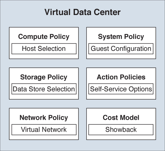
Each vDC will be made up of several policies that determine how new virtual machines will be deployed, managed, and billed back to the users and groups. Figure 9-1 provides a graphical representation of a vDC and the most important policies you will need to create.
Configuration of the vDC and policies is done in the Edit vDC window, accessed via the administrator portal by choosing Policies > Virtual/Hypervisor Policies > Virtual Data Centers, as shown in Figure 9-2. Each of the policies is leveraged by UCS Director when provisioning new virtual machines to the underlying hypervisor platform being leveraged. Therefore, you’ll find that there are tabs for each of the supported cloud types. The differences between the VMware System Policy and the HyperV System Policy, as an example, are minor, and once you understand the overall usage of each policy type, it is fairly easy to leverage a different cloud type. In our discussions of the policies, we will be assuming VMware vCenter as the cloud type.
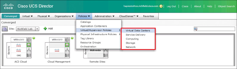
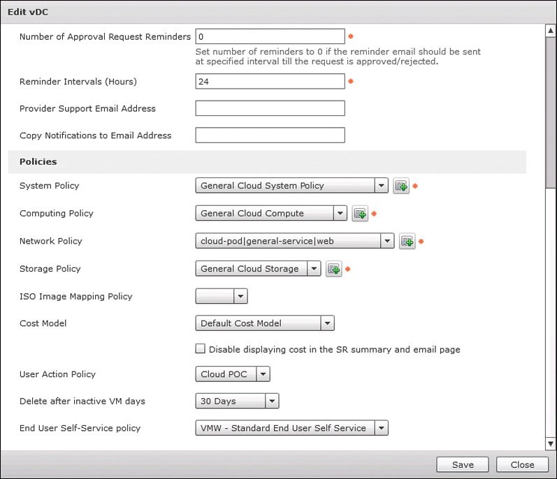
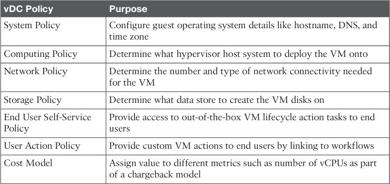
Figure 9-3 shows vDC properties where the different policies are applied. As indicated by the red asterisk, the System, Computing, Network, and Storage Policies are mandatory for vDC creation. Policies for Cost Model and User Action are optional. Table 9-2 provides a simple breakdown of each virtual data center policy and its purpose.
System Policy
You will find the System Policy under Policies > Virtual/Hypervisor Policies > Service Delivery along with other polices such as Cost Model, OS Licenses (Windows OS Product Keys), and other VM-level policies. The System Policy itself determines how the guest operating system will be configured during the customization phase of creation. As shown in Figure 9-4, the main policy elements are about VM and hostname format, time zone, and DNS settings. If you configure the policy for both Windows and Linux VMs, you’ll need to configure several Windows-specific elements for licensing and domain settings. Configuring a Windows Product ID/Key in the System Policy is optional, as it is more likely to attach the Product Key information to the Standard Catalogs to support multiple guest OS types within a single vDC.
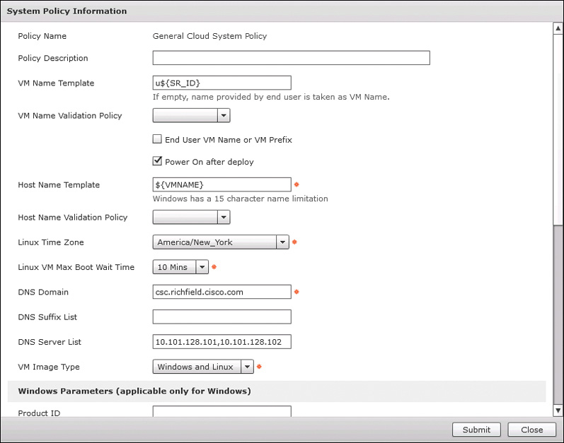
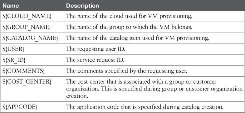
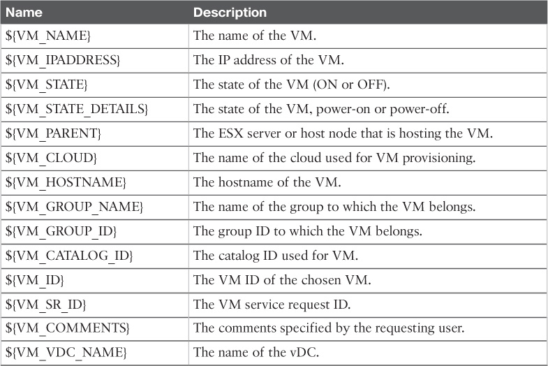
As you can see in Figure 9-4, UCS Director supports using variables within policies. Within UCS Director, variables are indicated and accessed through a ${Variable Name} syntax. For example, ${GROUP_NAME} would be replaced with the name of the group for which a resource is being provisioned, and ${USER_NAME} would represent the requesting user’s username. These variable references are often used when creating VM name and hostname templates as part of the System Policy. Table 9-3 lists and describes the available variables for use in creating hostnames and VM names.
Administrators can mix static characters with variables to create a template for name creation. For example, the VM Name Template setting shown in Figure 9-4 is u${SR_ID}. This will create a name in which the service request number will be preceded by a single lowercase “u” character. This type of name will ensure uniqueness for new virtual machines. Administrators can choose to allow end users to provide a prefix that would be inserted before the template configured in the policy.
Computing Policy
You use the VMware Computing Policy to give UCS Director the information it needs to select a vSphere host or cluster to deploy a new VM to. UCS Director will start by considering all available hosts or clusters that you indicate are available, and then filter down the selections by excluding any host that doesn’t meet the conditions specified in the policy. Figure 9-5 shows some of the common filter options, which you can use to enforce your organization’s standards for guest-to-host ratio, CPU/RAM oversubscription policies, and required available capacity on a single host.
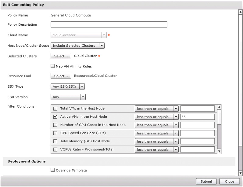
The default behavior for UCS Director when deploying a new VM is to maintain the underlying image/template settings for CPU and RAM. You can opt to give your users the ability to resize a VM at provision time by clicking the Resizing Options button near the bottom and providing a comma-separated list of options. The Override Template configuration in the policy would be a universal administrative override for all new VMs being deployed with this policy.
Network Policy
You configure network connectivity for virtual machines with the Network Policy. UCS Director supports single or multiple network connections per VM. And each can be configured for static or DHCP-assigned IP addresses. On occasions where you’d like to provide your end users some flexibility in network configuration when provisioning, you can even add choices regarding optional network adapters and the port groups being assigned.
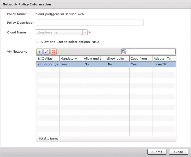
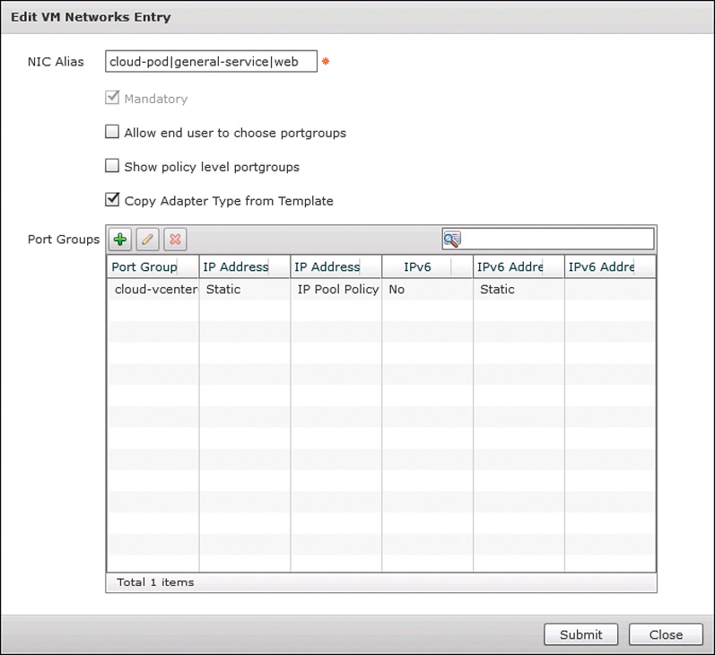
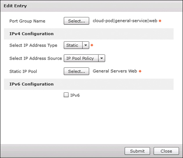
Figure 9-6 shows the main page of the VMware Network Policy. This page lists the number of VM networks (or virtual network adapters) this policy will configure. Clicking the Add button or Edit button above the table opens the dialog box shown in Figure 9-7 where you configure the settings for an individual network adapter. Each network entry has one or more port groups listed. Any single vNIC can be assigned only a single port group at a point in time. When multiple options exist, you can allow end users to choose their desired port group if you wish; otherwise, UCS Director will select the first one available (typically due to available IP addresses). Click the Add or Edit button in the Port Groups table to open the Edit Entry dialog box, shown in Figure 9-8, where the port-group and IP assignment configuration is completed. Configuring IPv6 connectivity is an optional setting in the policy.
Storage Policy
Your configuration of the VMware Storage Policy will determine what data store the VM’s disks will be stored on. Configured and applied very similarly to the Computing Policy, you will first indicate what possible data stores should be considered, and then what conditions would exclude an individual option. This enables you to ensure a single data store doesn’t get overprovisioned. Figure 9-9 shows the configuration window, including the key elements of data store selection and filters. Also similar to the Computing Policy, you can override the template disk sizes or allow your end users to resize at provisioning.

Be aware that when creating a new Storage Policy, all storage options (Local, NFS, and SAN) are selected by default. Be sure to specify which are appropriate for your cloud. A common mistake made by administrators is to leave Use Local Storage selected, in which case UCS Director will attempt to provision new VMs to local data stores.
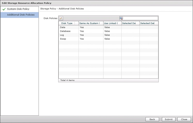
If your environment has different tiers of data stores for uses like databases, swap, or general data, you can indicate this type of configuration need in the Additional Disk Policies configuration of the Storage Policy, as shown in Figure 9-10.
Cost Model
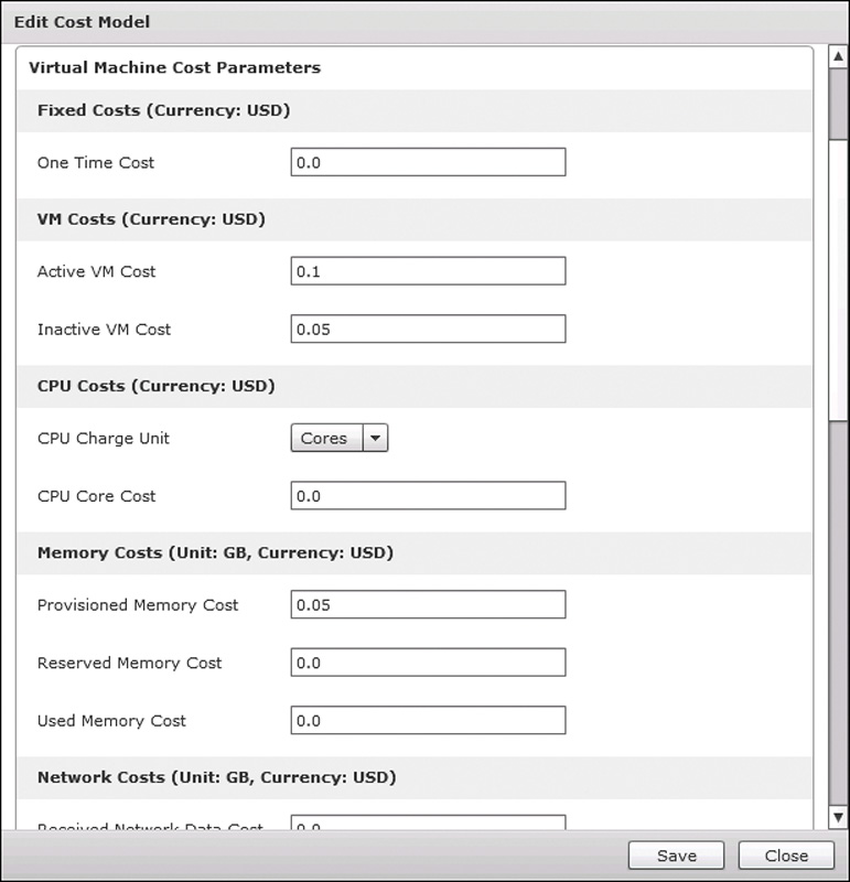
Applying a Cost Model to a virtual data center is an optional configuration for enterprises moving into a showback or chargeback model. To access the Cost Model configuration settings, choose Policies > Virtual/Hypervisor Policies > Service Delivery > Cost Model. UCS Director supports a very flexible metering and billing policy through the Cost Model policy. Charges can be issued hourly, daily, weekly, monthly, or yearly, and metrics for CPU, memory, network, and storage are all supported. Figure 9-11 shows an example section of a Cost Model configuration.
Note
Chapter 12, “Chargeback, Billing, and Reporting,” provides a complete discussion on chargeback and billing options.
Action Policies
In most cases, you will want to enable your users not only to provision new virtual machines, but also to self-manage the life cycle of those VMs. End-user productivity and satisfaction will not be much improved if end users need to open a ticket with IT every time they want to power on/off or snapshot their VM as they are managing or developing an application. There are two optional policies configurable within a vDC to enable users to take actions on their own VMs.
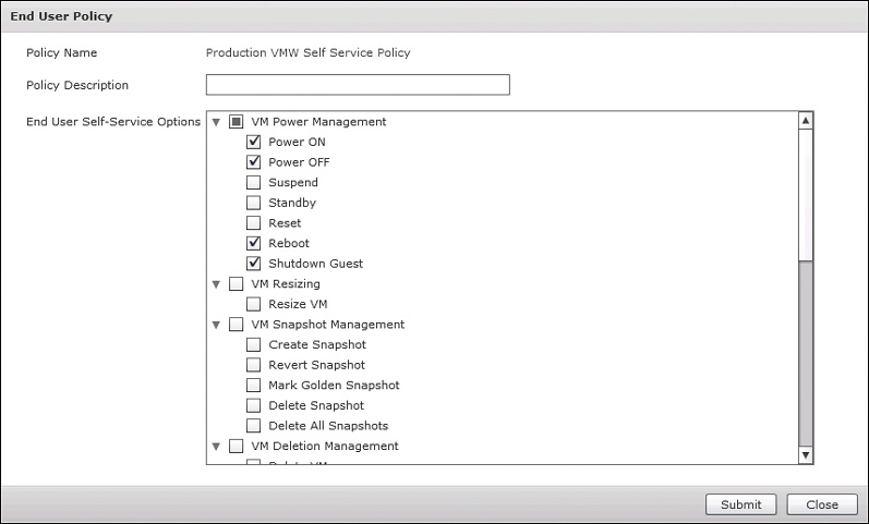
The End User Self-Service Policy is located at Policies > Virtual/Hypervisor Policies > Service Delivery > End User Self-Service Policy, and is the policy you will start with to offer end-user control of VMs. Shown in Figure 9-12, this policy provides you the options to enable which of the out-of-the-box actions supported by UCS Director the end user will have access to. There are greater than 30 possible actions you can enable covering basic power management, snapshot management, and VM resizing.
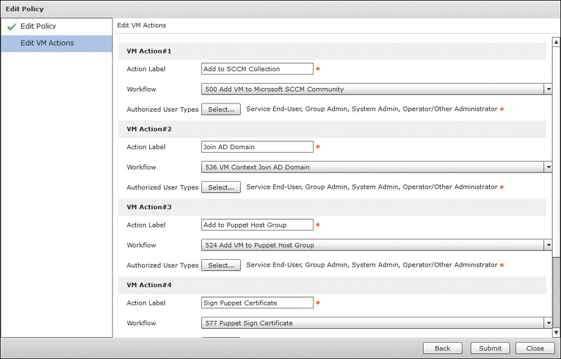
You will likely eventually find a need to enable end users to take some action on a VM that is not an out-of-the-box capability for UCS Director, or perhaps you may simply want to change or extend the behavior of an out-of-the-box task. In this case, you can build a workflow with a VM context for the new action and leverage the User Action Policy to give users access to the new capability. One common example is extending the Add VM Disk action to include mounting and formatting the disk in the guest operating system.
The User Action Policy is configured via the Policies > Orchestration menu four tabs down from Workflows. Figure 9-13 shows a sample policy with some example Actions that could be built.
vDC Categories
When you create a new vDC, part of the process is creating new policies, or selecting existing ones for each of the mandatory and optional types needed. This provides UCS Director the information needed to automatically deploy new VMs into the vDC based on the policy and governance needed by your organization. However, you will quickly realize that not all VMs deployed into a vDC have the same requirements for compute, network, and storage. Web and database servers have vastly different storage performance requirements. Some application servers may need a higher-performing CPU than a general server.
Virtual data center categories can help solve the problem of differentiating policies within a vDC. In the “Standard Catalog” section in Chapter 10, “Building a Service Catalog and User Portal with UCS Director and Prime Service Catalog,” you learn that when creating a Standard Catalog, one parameter you configure is the category of the catalog. The category selected corresponds to one of the available categories of a vDC.
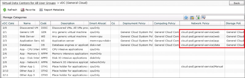
After creating a new vDC, you can select it in the Policies > Virtual/Hypervisor Policies > Virtual Data Centers menu and click Manage Categories from the action menu. Figure 9-14 shows a sample view of this interface, where you can see each of the categories listed with columns for each of the configured policies. Any policy setting configured here will override the default policy as configured on the vDC itself. In the figure you can see that the Network Policy has been adjusted to reflect web, app, and data port groups for the related categories.
IP, Subnet, and VLAN Network Pools
Part of automating infrastructure delivery includes consuming resources from the cloud. Within network automation, the three most common resources that will need to be consumed are IP addresses, subnets, and VLANs. Every enterprise network team will have some process for allocating and indicating use of these resources. Many organizations are still leveraging spreadsheets for manual tracking, while others have implemented enterprise IP address management (IPAM) tools.
Whatever method your organization is using, UCS Director supports a lite-IPAM capability that will enable it to automatically allocate and record the consumption of resources as they are provisioned to new virtual machines or during a workflow execution. You configure these pools and policies from Policies > Virtual/Hypervisor Policies > Network. Figure 9-15 shows the Static IP Pool Policy as well as the tabs for IP Subnet Pool Policy, VLAN Pool Policy, and VXLAN Pool Policy.
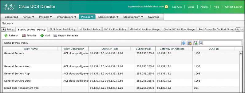
Static IP Pool Policy
The Static IP Pool Policy is a critical component of most vDC Network Policies because few data centers leverage DHCP for assigning IP addresses to servers. However, a single static IP pool can be used across many Network Policies as well as for any instance where an IP address from a given range is required. For example, if you build a workflow to build and provision a new bare-metal server, its IP address could come from the same pool used for VM IPs in a vDC Network Policy.
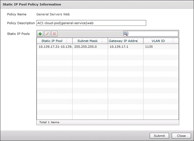
You add or edit a policy with an interface similar to Figure 9-16. A policy requires a name and optional description and one or more pools or ranges of IP addresses. If you configure more than one pool in a single policy, UCS Director will exhaust the first pool and then move to subsequent pools. Though a pool entry can include a VLAN ID, it is more for notation than an actionable piece of data. When an IP address is requested from a pool, a VLAN ID is not a consideration for determining an appropriate IP address.
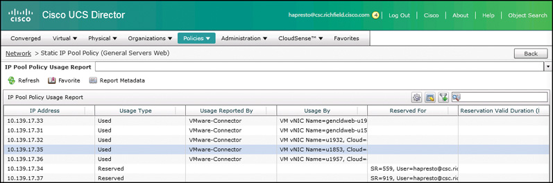
Once a policy is created, you can double-click its name to bring up a table similar to the one shown in Figure 9-17, where each of the used IP addresses is noted along with details regarding which VM or service request has it reserved. The reservation can be cleared by rolling back the service request, or manually by the administrator.
IP Subnet Pool Policy
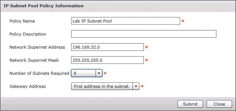
An IP Subnet Pool Policy is very handy when constructing automation jobs that will be building a new network segment that will require IP space to be assigned and configured. Some examples where you would do this include adding a new VLAN to a traditional network, creating a new bridge-domain subnet in an ACI-based network, or creating a level of segmentation with a firewall device.
You will only need a few pieces of information to create a new IP Subnet Pool Policy. In addition to the policy name and description, you’ll need to provide a network supernet address and mask, and indicate the number of subnets required. Finally, you indicate whether the gateway address should be the first or last available address in the subnet. This is helpful because the workflow task to generate a new subnet from a pool will provide several outputs to make using the new subnet easier, one of which is the gateway IP address. You can see an example of the interface in Figure 9-18.
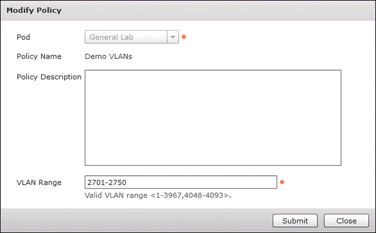
VLAN Pool Policy
You will leverage a VLAN Pool Policy to generate a new VLAN ID often along with using the IP Subnet Pool Policy to add new network segments. The VLAN Pool Policy is very simple, only requiring the range of VLAN IDs to use (see Figure 9-19).
Physical Infrastructure Policies
Your data center is made up of more than just virtual resources. Even if your application workloads are 100 percent virtualized, you still must have physical servers acting as hypervisors, storage arrays to provide disk space to store all the VMs, and a network for everything to communicate over. Because you will always have to work with both physical and virtual resources, UCS Director provides methods to configure these physical resources as well.
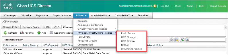
You will find that UCS Director offers many methods of configuring infrastructure as you become more familiar, but for this book we will be discussing what is available for assisting with provisioning new UCS service profiles. Figure 9-20 shows the location of both UCS Manager and UCS Central Policies, along with Rack Server (standalone Cisco C-Series) and NetApp Policies.
UCS Policies
UCS Manager and UCS Central Policies will be used when you are looking to build a new service profile template or a new service profile without using a service profile template. In these circumstances you will require UCS policies for storage and network configuration when creating a new service profile.
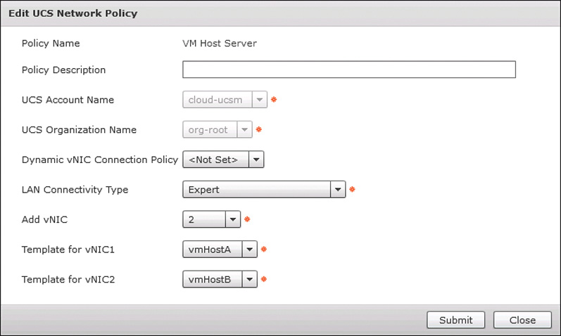
The UCS Manager (or UCS Central) Network Policy simply indicates the number and type of virtual NICs (vNIC) to configure in a new template. Figure 9-21 shows a sample UCS Manager Network Policy. In the UCS Network Policy, you specify UCS Director vNIC templates for the vNIC1 and vNIC2 templates displayed in the figure. It is typical to link the UCS Director vNIC template to an underlying UCS Manager or Central template.
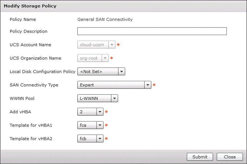
The UCS Manager Storage Policy does the same thing for virtual host bus adapters (vHBA) as the UCS Manager Network Policy does for vNICs. Figure 9-22 provides a sample.
Regarding UCS Manager and UCS Central policies, templates and profiles, UCS Director will allow the creation of policies using local (from UCS Manager) or global (from UCS Central) templates; however, you should avoid mixing them when you create a service profile or template in UCS Director. Either use only local or use only global objects underlying your policies.
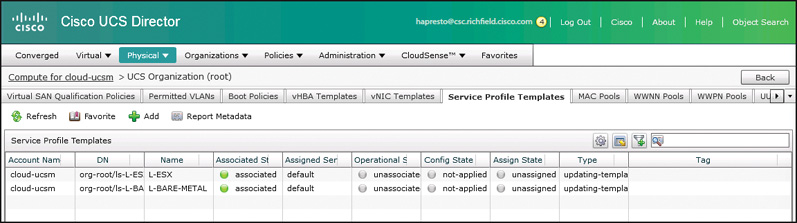
Once you have created the necessary policies, you can create a new service profile or template within UCS Director that leverages them. Most often you will create a service profile or template as part of a workflow, but you can also create one on demand by navigating to Physical > Compute and locating your UCS Account in the tree menu on the left. On the Organizations tab, double-click the UCS Organization that your new service profile or template will be created within, and then switch to the Profile or Templates tab. Figure 9-23 shows UCS Director navigated to the Service Profile Templates page.
Click the Add button to open the Create Service Profile Template dialog box, shown in Figure 9-24, where you can create a new service profile template within your UCS environment. The Storage and Network Policies are used within this dialog box to create the desired connectivity options.
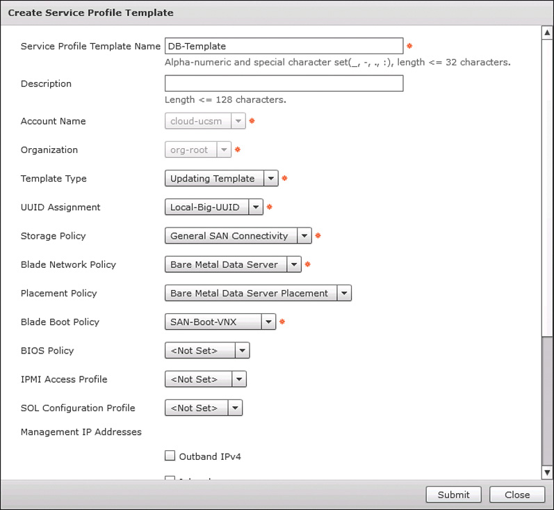
Within the dialog box to create the new service profile template is a Template Type field with options for Updating Template or Initial Template. This is an important characteristic of the service profile template to understand. New service profiles created from an Initial Template will match the template’s settings at the time of creation, but if the template were to be updated in the future, any service profiles already created would not be affected. With an Updating Template, changes to the template will also change all service profiles created and bound to the service profile template. There are circumstances where you may want to leverage both of these template types within your organization. For example, your critical production database servers may be created based on Initial Templates because any updates or changes to that server must be well planned and explicitly addressed per server. However, your virtualization host servers would be created based on Updating Templates to make sure that each host in your cluster has consistent settings when changes happen, such as new VLANs being added to vNICs.
UCS Director Orchestration
You will really start adding value to your enterprise when you begin automating the day-to-day infrastructure delivery tasks that typically require significant planning and manual processes to complete. Enterprise IT organizations receive tasks from end users, such as “provision five new bare-metal servers for a new database cluster,” and tasks more targeted at IT operational activities, such as “add capacity to the virtualization farm.” In both of these cases, providing a method to provision through automation in a matter of minutes transforms the way enterprises look at IT’s delivery capabilities.
Workflows
There is really no end to the possibilities for what you could do with UCS Director workflows, but you will find the types of tasks it is well suited for involve infrastructure provisioning and configuration tasks across the tiers of virtualization, compute, network, and storage. Here is a short list of some use cases you may consider ideal candidates for automation with UCS Director:
![]() Deploy one or more virtual machines
Deploy one or more virtual machines
![]() Deploy new bare-metal servers for running applications on a Windows or Linux OS (including full configuration of physical compute, storage, and network requirements)
Deploy new bare-metal servers for running applications on a Windows or Linux OS (including full configuration of physical compute, storage, and network requirements)
![]() Expand the cloud capacity of an existing virtualization solution, by adding either new compute hosts or shared storage
Expand the cloud capacity of an existing virtualization solution, by adding either new compute hosts or shared storage
![]() Add a new network segment to the data center across physical, virtual, and compute networking domains
Add a new network segment to the data center across physical, virtual, and compute networking domains
![]() Add new data drives to a virtual machine, including mounting and formatting
Add new data drives to a virtual machine, including mounting and formatting
![]() Perform snapshot maintenance and purging across all VMs in the cloud
Perform snapshot maintenance and purging across all VMs in the cloud
![]() Create or update a help desk ticket in an external ticketing system
Create or update a help desk ticket in an external ticketing system
![]() Construct a standard three-tier application environment including network segmentation, security policy, and load-balancing rules
Construct a standard three-tier application environment including network segmentation, security policy, and load-balancing rules
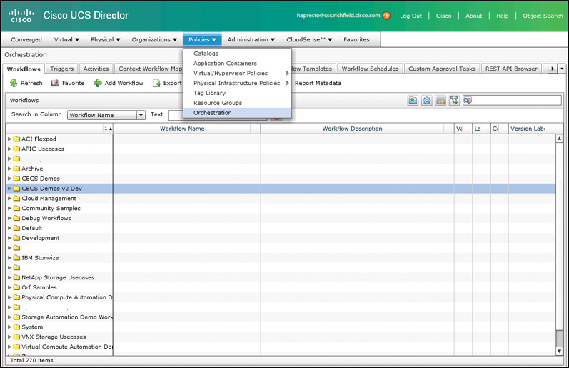
Locate the Orchestration capabilities of UCS Director under Policies > Orchestration. Figure 9-25 shows the menu location and the initial view of the Orchestration module. You will find there are several tabs and sections of the Orchestration engine. As you become more advanced, you will learn to leverage many of the capabilities available within this interface; however, for now we will focus on the first tab, Workflows, where you build and edit workflows.
Workflow Properties
Every workflow has a set of properties along with the actual automation logic. The first thing you will see after clicking Add to create a new workflow is the Add Workflow screen. Or you can click Edit Workflow on an existing workflow to view or make changes. As shown in Figure 9-26, the first page of the Edit Workflow window, Edit Workflow Details, includes the Workflow Name, which cannot be changed after initial creation, a Description field, and several other important workflow characteristics.
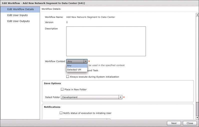
The Workflow Context field has two possible options, Any or Selected VM. Most general-purpose workflows will have a context of Any, but if you are building a workflow that is specifically intended to operate on a single VM, you can use Selected VM as the context. One advantage of setting up your workflow this way is that you will immediately have access to several inputs for tasks for details about the VM, such as its name and IP address. Table 9-4 provides a list of the additional variables available when working in a VM context. Second, this is the type of workflow you will want to use if you are building something intended to become part of a User Action Policy, as discussed earlier in this chapter.
Another important property to be familiar with is the ability to save the workflow as a compound task. This means that once the new workflow is created, it will show up in the Task Library (discussed in the next section, “Workflow Designer”) as a reusable task. This allows for you to build reusable automation structures and use them within other workflows, providing for modular development. Then when you update the underlying compound workflow, all other workflows leveraging it will immediately benefit from the changes.
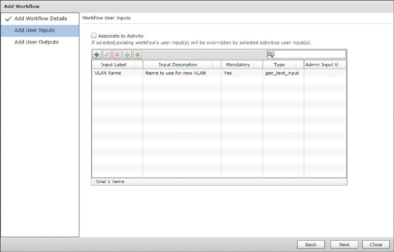
On the second page of the Edit Workflow window, Edit User Inputs, you indicate the number and types of user inputs that will be gathered, as shown in Figure 9-27. These user inputs are a collection of variables that can be leveraged during workflow execution. Some of these variables will come from the end users when they either directly execute a workflow or order an Advanced Catalog backed by your workflow. Others can be administratively defined by the user building the workflow. Common user inputs include names or descriptions for servers or networks, IP address details, username and passwords for systems, detail selections such as the operating system or application tier needed for a new server, and so on. The workflow shown in Figure 9-27 will add a new network segment to the data center. The end user provides the VLAN name to use for the new network, but other inputs you might expect, such as VLAN ID or IP subnet, will be dynamically determined from configured pools as described earlier in the chapter.

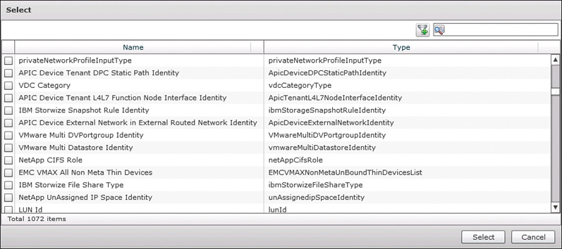
One important aspect of user inputs, and of all inputs and outputs in workflows, is that UCS Director has a strongly typed model for variables. Each input will be assigned one of many types, and when you later go to use that input within a workflow task, the type of the user input must match the type that the task is expecting. The one exception to this rule is the Generic Text Input (gen_text_input) option. In most cases, any workflow task input will accept a Generic Text Input; however, it is recommended to use this sparingly. Leveraging a type of IP address or VLAN ID for an input has the added benefit that UCS Director will make sure the value provided by the user fits the type of input expected. This means that a user would not be able to enter a value of 555.555.555.555 for an IP address. Figure 9-28 shows a sample of some of the input types available within UCS Director.
The final page of the Edit Workflow window is Edit User Outputs. Workflow outputs are used in compound tasks to pass information up to the parent workflow. Though all task outputs from the child task can be made available, often it is a subset of these outputs that will be of interest in the parent workflow. By mapping the relevant values to workflow outputs, it is much simpler to build complex workflows.
Workflow Designer
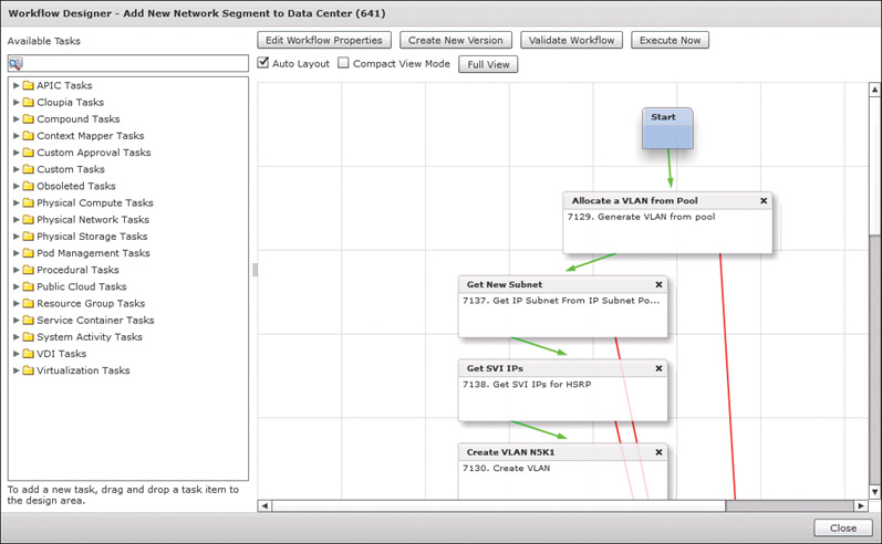
The Workflow Designer is where you build the actual automation structure for the workflow. You can access it by double-clicking the workflow name or by clicking the Workflow Designer button on the toolbar. Figure 9-29 shows an example of what you will see. The main section of the interface is the workspace where you drag and connect individual tasks, double-click a task to configure the task inputs to leverage a user input, output from a previous task, or administratively define the input within the task. On the left side is the Task Library, where you will find all of the available tasks organized into folders. UCS Director 5.3 ships with over 1600 tasks out of the box, and while the folder organization helps, you will often find it faster to locate a needed task by using the search box above the list. At the top of the window are buttons that allow you to edit the workflow properties, create a new version of a workflow, validate the workflow (ensure all tasks are connected and have all mandatory inputs configured), and execute the workflow.
Workflow Creation Walkthrough
Let’s walk through the creation of a simple sample workflow that adds a new VLAN to a Cisco Nexus switch. We will prompt the user for a VLAN name at execution, but will determine the VLAN ID by selecting one from a VLAN Pool Policy within UCS Director.
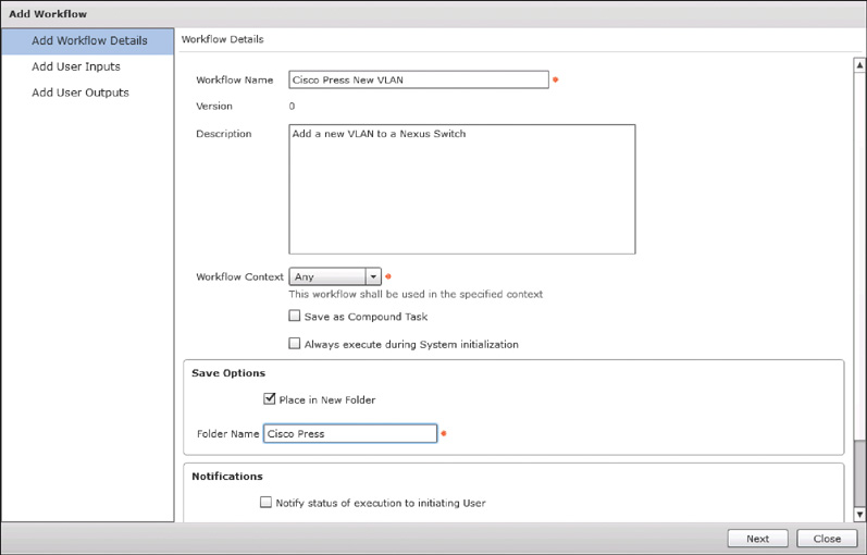
To begin, we need to create a new workflow using the procedure discussed in the previous “Workflow Properties” section. Figure 9-30 shows the Add Workflow Details page filled in for our new workflow, and Figure 9-31 shows the Add User Inputs page configured to prompt the user for a VLAN name.
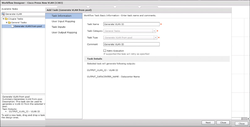
Next, open the Workflow Designer to begin creating our new workflow. Two pieces of information are required to add a VLAN to a switch: the name and ID. The user will provide the name, but we need to generate the ID within the workflow. UCS Director provides tasks to generate available resources from pools and policies, and as shown in Figure 9-32, we leverage a task called Generate VLAN from pool. After dragging this task into the Workflow Designer pallet, we provide a descriptive name and comment for our task and click Next to continue.
For this task we are not mapping any user inputs into the task, so skip the User Input Mapping page by clicking Next and move to the Task Inputs page. Here, as shown in Figure 9-33, we define the VLAN Pool Policy from which a new VLAN ID will be generated. Click Next and Submit on the Use Output Mapping page to save the task.
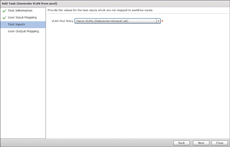
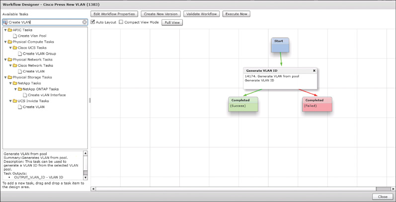
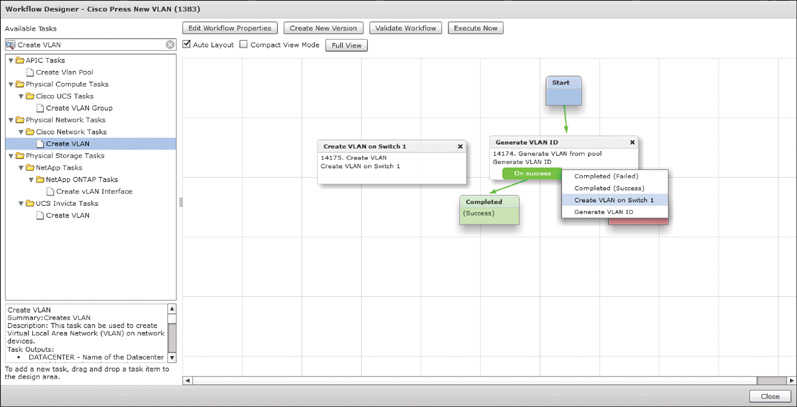
Figure 9-34 shows this first task complete and added to the design, automatically connected to Start and Completed blocks. Also shown on the left in the figure are the many possible tasks to create a new VLAN. Drag the Create VLAN task from the Cisco Network Tasks group onto the Workflow Designer for our next step.
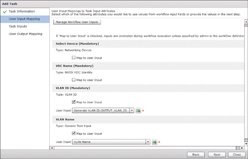
The first step after dragging any new task into the Designer is to provide it a name and comment. For this task, we use “Create VLAN on Switch 1” for both the name and comment. After you click Next, Figure 9-35 shows the User Input Mapping page of the task, where we checked the Map to User Input check boxes for VLAN ID and VLAN Name. This allows us to select either a workflow input, such as VLAN Name, or a previous task output, such as Generate VLAN ID.OUTPUT_VLAN_ID, to use as the task inputs. The latter example shows the notation used to reference task outputs within UCS Director with a TASK_NAME.OUTPUT_NAME structure.
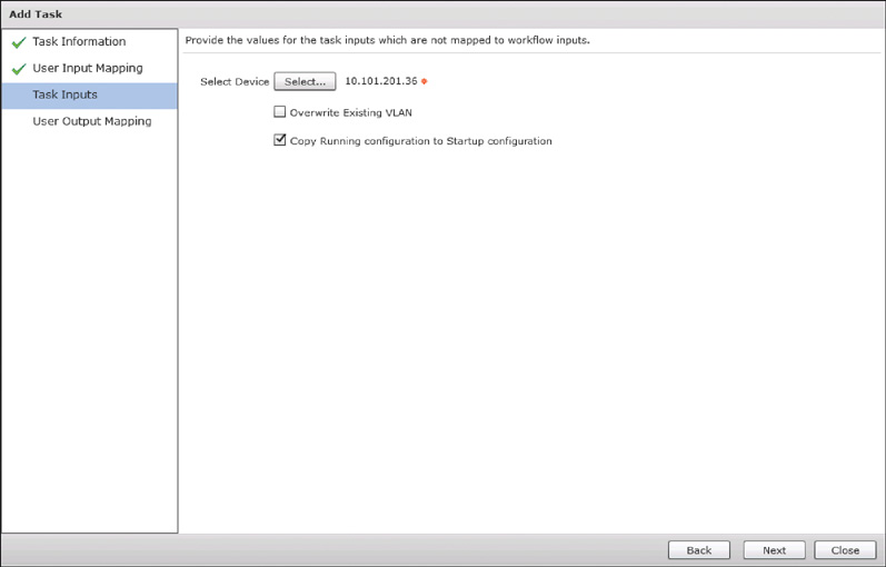
Not all of the task inputs are mapped to user inputs. After clicking Next, in Figure 9-36 we are identifying which switch we will be adding this VLAN to. Click Next and Submit on the Use Output Mapping page to save the task.
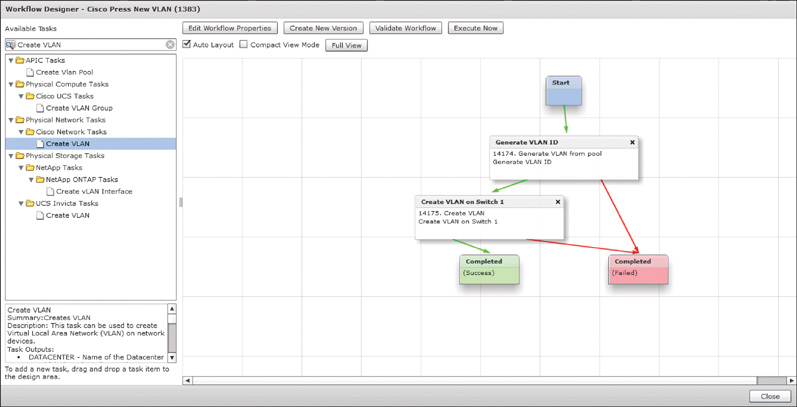
After finishing the configuration of the task inputs, we still need to place the new task into the workflow processing structure. Only the first task added to a workflow is automatically added, and in Figure 9-37 we are indicating that a successful completion of the first task will lead to our new task. Figure 9-38 shows the Workflow Designer with both tasks completely configured.
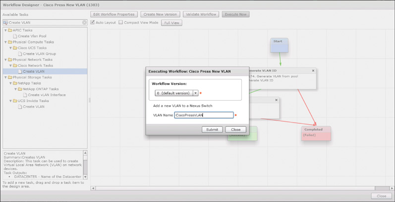
The final step in our walkthrough is shown in Figure 9-39, where we have validated our new workflow and executed it. As expected, we are prompted to provide a new VLAN name to continue.
Extending Orchestration
With practice, you will be able to build workflows that are very powerful, spanning across your infrastructure using only the available tasks shipped with UCS Director out of the box. However, there will come a time when you look for a task to accomplish some configuration or customization and it is not available natively. When confronted with this challenge, there are several options for extending the automation capabilities beyond the initial installation.
Following are descriptions of the most common methods for extending Orchestration within UCS Director. Advanced discussion of these methods is beyond the scope of this book, and leveraging them is not part of the exam topics. Review the Cisco UCS Director Orchestration Guide and Programming Cookbooks available in the Programming Guides on Cisco.com for UCS Director.
Cloupia Script
One of the first tools you will likely use is the Execute Cloupia Script task that is within the native library. This task provides you with a text input box where you can enter raw Cloupia Script to be executed during a workflow, enabling you to write the code needed to fill a need in your workflow. Cloupia Script is a slightly customized version of JavaScript that combines the JavaScript language with included libraries to access runtime details from UCS Director itself. Within a Cloupia Script you’ll have access to a context object that relates to the running instance of your workflow. This object provides details such as the requesting user, the service request details, user inputs, and task outputs.
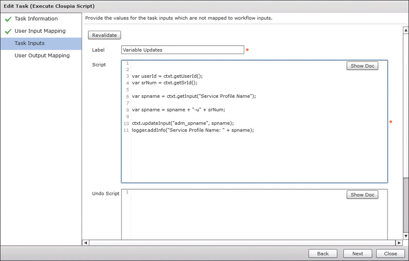
Most Cloupia Scripts that you will write will be very simple functions. A common example would be manipulating a user input to meet some organizational standard. Figure 9-40 shows one such example where a user-provided name is appended with the service request number to ensure uniqueness and document the source of the new service profile.
Custom Tasks
If you find that you are continually using the same Cloupia Script within several workflows, or have a need for something more complicated, the next option you have is to create a Custom Task. Custom Tasks are also written in Cloupia Script but are built to be much more reusable and portable between workflows. You will create task inputs and outputs, have an option to control the behavior of the task input interface to take action based on certain input values affecting others, and build your code using the same JavaScript-style construction from Cloupia Script. Once created, the Custom Task will show up in the Task Library under the Custom Tasks folder, and further organized as you indicated when creating the task.
Custom Approval Task
Many organizations find that though the goal may be full automation of infrastructure requests, many start with a need to insert approval steps into a workflow. You will find included tasks for single and multiuser approval capabilities that will pause a workflow while waiting for the designated users to indicate their approval for the request. This can be very helpful. However, what about a case where the approver needs to provide some input back to the workflow to complete execution? For example, consider an example where a new server is being provisioned, and the network operations team needs to identify the proper VLAN to place the server onto. For cases like these, you will build a custom approval task to use in your workflows.
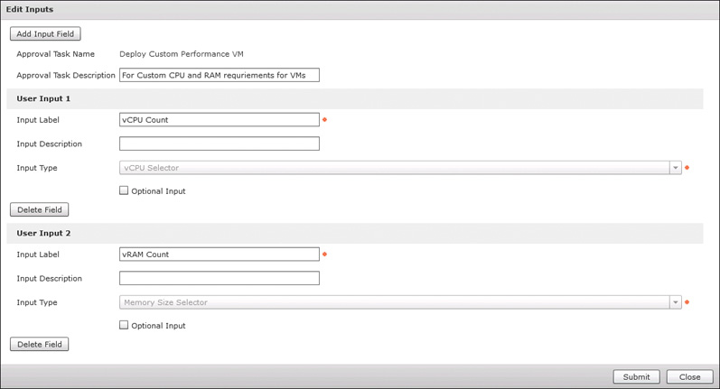
You can create Custom Approval Tasks in the Orchestration interface several tabs to the right of the Workflow list. Each Custom Approval Task can be used in multiple workflows. Once created, the new task will show up in the Task Library along with all the others in a folder called Custom Approvals. Figure 9-41 shows an example Custom Approval Task where the approver will be asked to provide the vCPU and vRAM size information for a new VM.
Custom Workflow Input
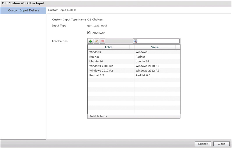
You learned about the strongly typed nature of inputs within UCS Director in the “Workflow Designer” section of this chapter. There are hundreds of input types out of the box covering everything from general details like IP address and VLAN ID to infrastructure-specific types like a UCS service profile. However, you may find that you want to have your user provide input but offer a limited selection of choices. A typical example would be choosing one option from a set of appropriate entries in a drop-down list (referred to as an LOV, or list of values). You will use the Custom Workflow Input to build a new input type to use in your workflows. When you create the Custom Workflow Input, it will be based on a native type, and useable wherever that native type is supported. Figure 9-42 shows an example Custom Workflow Input called OS Choices that is based on a Generic Text Input and provides the user with a list of available operating systems supported in our environment. You can then use this input from the end user within the workflow as part of a branching logic to differentiate some aspect of the configuration based on the operating system in question.
Cisco Community
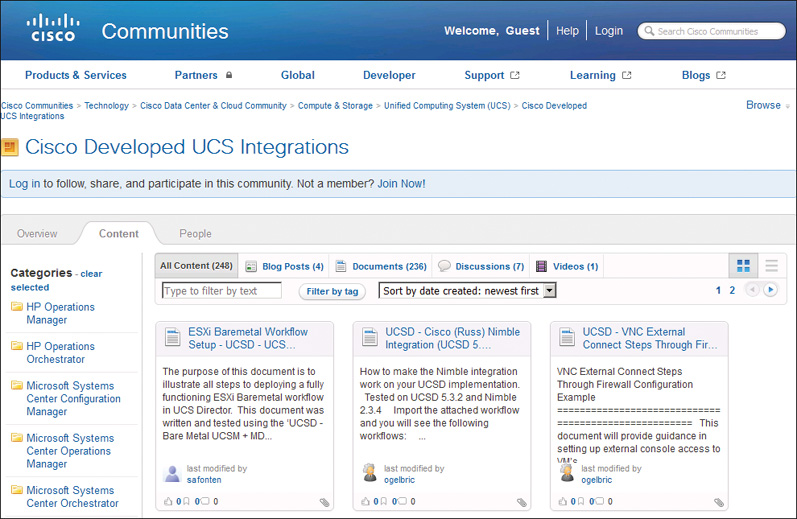
You are not alone when creating workflows and automation use cases with UCS Director, and you needn’t always start from an empty workflow. There is a Cisco Development Community where Cisco customers, partners, and employees share examples of work being done with all Cisco products, including UCS Director. At the time of the writing of this book, there are over 300 example workflows posted to the community that you can search and download to import into your system to use as inspiration or starting points for your own workflows, and more are being added weekly. In addition to sample workflows, there are many Custom Tasks that have been built to extend the native features of UCS Director to solve problems and fill gaps that others have found. When confronted with something that you may need, before building it yourself, take a look at the community to see if someone has already built a working task.
Also, you can often find third-party integrations posted in the community. At the time of writing, integrations to the Infoblox IPAM solution and Nimble Storage Array are two examples shared on the community.
You can find the home page for Cisco Communities at http://communities.cisco.com. The sample UCS Director workflows are located by navigating to Data Center Community > Unified Computing System (UCS) > UCS Integrations > UCS Director Workflows. See Figure 9-43 for a glimpse into the community.
UCS Director Service Requests
Any activity that would execute a workflow will generate a service request within UCS Director. This includes ordering any of the UCS Director Catalog types (even Standard Catalogs execute a workflow), or manually executing a workflow through the Designer or the Orchestration interface. Even rolling back a service request creates a new service request. The service request is a record of a single automation activity, and stores all the details about who initiated the request, the status and time for each step in the workflow, detailed logging throughout, and all infrastructure manipulations made during its execution.
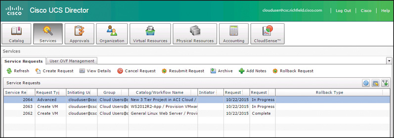
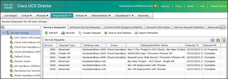
Service requests are available to be viewed and leveraged in both the administrator portal and the end-user portal, but the type of details available differ. An end user will only have visibility to the service requests initiated by themselves or other members of their group. Figure 9-44 shows the Services page of the end-user portal. The user sees only three requests that were initiated. Compare this to the page available in the administrator portal at Organizations > Service Requests shown in Figure 9-45. The administrator sees the three requests executed by clouduser as well as those executed by user cloudadmin. Also notice that administrators have access to the archived service requests. Though end users can archive one of their service requests, they can’t view or unarchive the archived requests.
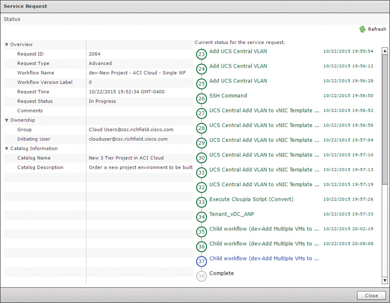
When an end user opens a service request to see more information, he will see the service request Status information, as shown in Figure 9-46. The Status page provides details on the request such as its Request ID, current status, the group and user who own the request, as well as a listing of each step or task in the underlying workflow indicating which steps have completed successfully (displayed in green with a time stamp) and which are currently in progress (displayed in blue), and, if applicable, which steps may have had errors (displayed in red or orange). The Status page is very helpful for end users to understand their request, but lacks the details available to an administrator in other tabs.
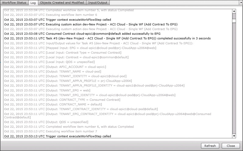
When you open a request as an administrator, the most helpful details are available on the Log tab, shown in Figure 9-47. You will find a very detailed rundown of the entire workflow and each included task. All inputs and outputs for each task are listed within the log to make it very easy to follow the progress as values change and new objects are created. When you are building a new workflow and troubleshooting a behavior that isn’t working as you intended, your best tool for debugging and fixing the problem will be the Log view of your service requests. Within the Log view, different colors indicate different types of messages. Informational messages are shown in black, debug messages in gray, errors in red, and warnings in orange.
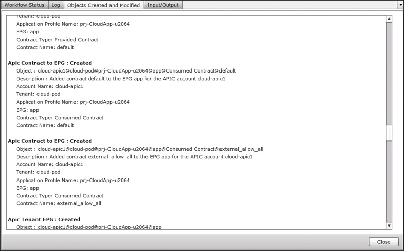
As an administrator, you will also have access to two other tabs providing details about the service request. First is the Objects Created and Modified tab, which shows some of the change-tracking capabilities of UCS Director. This view will list all VMs created, IP addresses reserved, VLANs created, LUNs created, and interfaces manipulated during the execution of the service request. An example of this view is shown in Figure 9-48. This information is useful as part of managing change, but even more important is how UCS Director can use this when rolling back or undoing a service request. The last tab is the Input/Output tab, where you will find a list of each task in the workflow and a breakdown of the different inputs and outputs involved. These details are also helpful during debugging workflows, or simply determining details such as what was the LUN ID of the new storage device that was created.
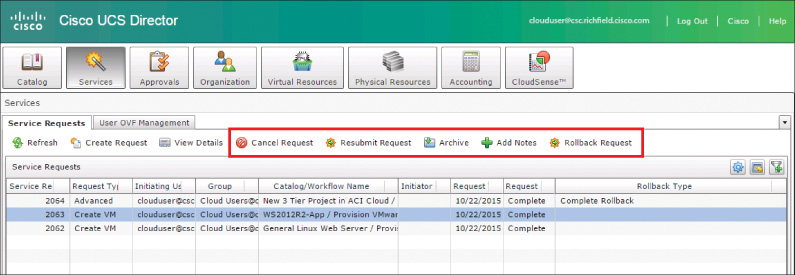
Service Request Actions
A service request is not a read-only object in UCS Director. You can take several actions on a service request depending on its current status. The actions are available for both administrators and end users through their portal interfaces in the toolbar, as shown in Figure 9-49. You can cancel a service request that is still in progress, stopping execution at the current task. You can resubmit a request if it was canceled or failed during initial execution. This is helpful when the reason for a failure can be solved and you want to just pick up the automation from where it left off. A common example of this would be the exhaustion of an IP pool. Once additional IPs are made available, you can resubmit the request and continue from where it initially failed. Archiving a service request moves it from the main list of requests that is available to end users, and into the Archive. Once a service request is in the Archive, only administrators can view it or take action on it. Administrators do have the ability to return an archived request to the main list.
The most powerful of service request actions is the ability to roll back the request. A unique value provided with the automation engine of UCS Director is the integrated ability to roll back any automation workflow. UCS Director is model based, not script based. This means that a task from the library that takes an action, such as creating a new VLAN, can be undone without needing a separate task that would delete the VLAN. All tasks included in UCS Director include the capability to be rolled back, and it is best practice to consider rollback for any custom tasks or scripts you may create.
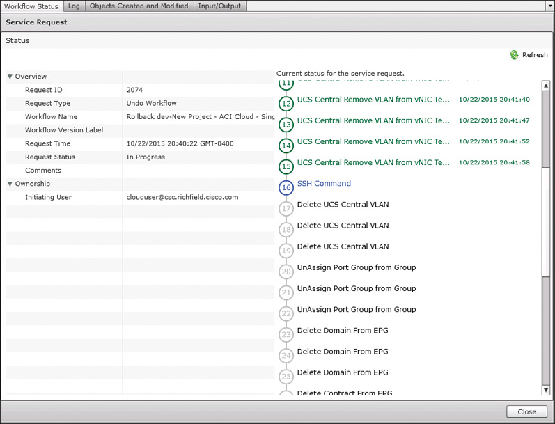
You won’t need to build separate workflows to reclaim or delete resources; that logic is included when you build the initial workflow. This capability combined with the details stored in Objects Created and Modified view (previously shown in Figure 9-48) enable UCS Director to immediately and consistently roll back service requests that are executed. When you choose to roll back a service request, a new Undo service request is created. If you were not the originator of the service request being rolled back, an approval request will be sent to the original requester. UCS Director administrators have the ability to bypass this approval step. A sample Undo service request is shown in Figure 9-50. Notice that the Undo Workflow is mostly a reverse mirror of the tasks taken in the initial workflow.
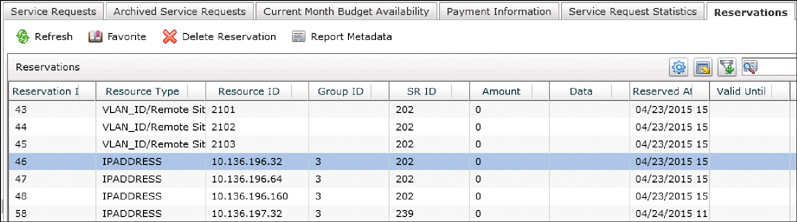
Reservations
Another tab in the Organizations > Service Requests menu worth noting is the Reservations tab. This tab, shown in Figure 9-51, provides a single view of all consumable resources that have been assigned from policies and pools to different users and groups as part of service requests. Common examples of reservations include IP address and VLANs. This view is useful for checking the status of different reservations, but can also be used to manually clear a reservation in a case where the object may have been deleted outside of UCS Director so that the reservation wasn’t automatically cleared as part of a rollback.
Exam Preparation Tasks
As mentioned in the section “How to Use This Book” in the Introduction, you have a couple of choices for exam preparation: the exercises here, Chapter 15, “Final Preparation,” and the exam simulation questions on the Pearson IT Certification Practice Test.
Review All Key Topics
Review the most important topics in this chapter, noted with the Key Topics icon in the outer margin of the page. Table 9-5 lists a reference of these key topics and the page number on which each is found.
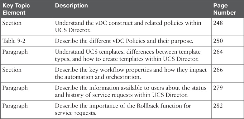
Table 9-5 Key Topics for Chapter 9
Define Key Terms
Define the following key terms from this chapter and check your answers in the glossary: