
Chapter 7
Cisco Next-Generation Firewalls and Cisco Next-Generation Intrusion Prevention Systems
This chapter covers the following topics:
Comparing Network Security Solutions That Provide Firewall Capabilities
Deployment Modes of Network Security Solutions and Architectures That Provide Firewall Capabilities
High Availability and Clustering
Cisco Firepower Intrusion Policies
Cisco Advanced Malware Protection (AMP)
The following SCOR 350-701 exam objectives are covered in this chapter:
Domain 2.0 Network Security
2.1 Compare network security solutions that provide intrusion prevention and firewall capabilities
2.2 Describe deployment models of network security solutions and architectures that provide intrusion prevention and firewall capabilities
2.5 Implement segmentation, access control policies, AVC, URL filtering, and malware protection
2.6 Implement management options for network security solutions such as intrusion prevention and perimeter security
“Do I Know This Already?” Quiz
The “Do I Know This Already?” quiz allows you to assess whether you should read this entire chapter thoroughly or jump to the “Exam Preparation Tasks” section. If you are in doubt about your answers to these questions or your own assessment of your knowledge of the topics, read the entire chapter. Table 7-1 lists the major headings in this chapter and their corresponding “Do I Know This Already?” quiz questions. You can find the answers in Appendix A, “Answers to the ‘Do I Know This Already?’ Quizzes and Q&A Sections.”
Table 7-1 “Do I Know This Already?” Section-to-Question Mapping
Foundation Topics Section |
Questions |
Introduction to Cisco Next-Generation Firewalls (NGFW) and Next-Generation Intrusion Prevention System (NGIPS) |
1 |
Comparing Network Security Solutions That Provide Firewall Capabilities |
2 |
Deployment Modes of Network Security Solutions and Architectures That Provide Firewall Capabilities |
3–5 |
High Availability and Clustering |
6 |
Implementing Access Control |
7–8 |
Cisco Firepower Intrusion Policies |
9 |
Cisco Advanced Malware Protection (AMP) |
10 |
1. Which of the following Cisco firewalls is designed for very large enterprises and service providers?
Cisco Zone-Based Firewall (ZBFW)
Cisco Firepower 9300 appliances
Cisco FTD running Cisco Unified Computing System (UCS) E-Series blades installed on Cisco ISR routers
Cisco Firepower 2140
2. Cisco IOS Zone-Based Firewall (ZBFW) can be deployed to provide firewall services in small and medium-sized organizations. Which of the following is not true about zone-based firewalls?
With ZBFWs, an interface can be assigned to only one security zone.
Zone-based firewalls cannot be implemented in an SD-WAN solution.
ZBFWs support zone pairs, which are a container that associates a source zone with a destination zone and that applies a firewall policy to the traffic that flows between the two zones.
ZBFWs support a security policy, similar to a localized security policy, that defines the conditions that the data traffic flow from the source zone must match to allow the flow to continue to the destination zone.
3. You were hired to deploy a Cisco ASA to provide separation of management and policies on a shared appliance. Which operational mode is best for this scenario?
Routed mode
Transparent mode
Multiple context mode
ERSPAN with tap mode
4. Which of the following statements is not true about firewalls deployed in Layer 3 (routed) mode?
Routed firewalls do not provide a way to filter packets that traverse from one host to another in the same LAN segment.
The Layer 3 firewalls require a new network segment to be created when they are inserted into a network, which requires quite a bit of planning, network downtime, and reconfiguration of network devices.
Layer 3 firewalls support EtherType ACLs.
In Cisco FTD deployments, ERSPAN interfaces are only supported in routed mode.
5. Which of the following statements are true about the inline interface sets and passive interfaces in Cisco FTD deployments?
Inline sets and passive interfaces are only supported on physical interfaces and EtherChannels.
Inline sets cannot use redundant interfaces or VLANs.
Inline sets and passive interfaces are supported in intra-chassis and inter-chassis clustering.
All of these answers are correct.
6. Which of the following are requirements for failover configurations?
The two participant devices must be configured in the same firewall mode (for example, routed or transparent).
The two participant devices must be running the same software version.
You can configure different Cisco FTD devices in groups (or domains) in the Cisco FMC. Devices configured for failover must be in the same domain or group on the Cisco FMC.
All of these answers are correct.
7. In Cisco ASA deployments, an access control list (ACL) is a collection of security rules or policies that allows or denies packets after looking at the packet headers and other attributes. Each permit or deny statement in the ACL is referred to as an access control entry (ACE). These ACEs classify packets by inspecting Layer 2 through Layer 7 headers for a number of parameters, including which of the following?
Layer 2 protocol information such as EtherTypes
Layer 3 header information such as source and destination IP addresses
Layer 4 header information such as source and destination TCP or UDP ports
All of these answers are correct.
8. You were tasked to configure a Cisco ASA to permit SMTP traffic from hosts in 192.168.88.0/25 to an email server (10.2.2.2). Which of the following access control entries (ACEs) in an ACL will accomplish this task?
access-list my-list extended permit eq 25 tcp 192.168.88.0 255.255.255.128 host 10.2.2.2
access-list my-list extended permit tcp 192.168.88.0 255.255.255.192 host 10.2.2.2 eq 25
access-list my-list extended permit tcp 192.168.88.0 255.255.255.128 host 10.2.2.2 eq 25
access-list my-list extended permit tcp host 10.2.2.2 192.168.88.0 255.255.255.128 eq 25
9. Which of the following is true about Cisco Firepower Intrusion Policies?
Both network analysis and intrusion policies are invoked by a parent access control policy, but at different times.
As the system analyzes traffic, the network analysis (decoding and preprocessing) phase occurs before and separately from the intrusion prevention (additional preprocessing and intrusion rules) phase.
The Cisco FTD has several similarly named network analysis and intrusion policies (for example, Balanced Security and Connectivity) that complement and work with each other.
All of these answers are correct.
10. Which of the following sandboxing technologies provides a dynamic analysis that includes an external kernel monitor, dynamic disk analysis that illuminates any modifications to the physical disk (such as the master boot record), monitoring user interaction, video capture and playback, process information, artifacts, and network traffic?
Threat Grid
Talos
Cisco Threat Response (CTR)
None of the above
Foundation Topics
Introduction to Cisco Next-Generation Firewalls (NGFW) and Next-Generation Intrusion Prevention Systems (NGIPS)
Cisco next-generation security products provide protection throughout the attack continuum. Devices such as the Cisco ASA with FirePOWER Services, available on the Cisco ASA 5500-X Series and ASA 5585-X Adaptive Security Appliances; Firepower Threat Defense (FTD); and Cisco Advanced Malware Protection (AMP) provide a security solution that helps discover threats and enforce and harden policies before an attack takes place. In addition, you can detect, block, and defend against attacks that have already taken place with next-generation intrusion prevention systems (NGIPSs), Email Security, and Web Security Appliance with AMP. These solutions provide the capabilities to contain and remediate an attack to minimize data loss and additional network degradation. Email Security and Web Security Appliances are covered in Chapter 10, “Content Security.”
You may have seen the terms FirePOWER and Firepower being used by Cisco in different instances. What is the difference between FirePOWER and Firepower? Cisco uses the term FirePOWER (uppercase POWER) when referring to the Cisco ASA FirePOWER Services module and uses Firepower (lowercase power) when referring to the FTD unified image and newer software.
Cisco Firewall History and Legacy
Cisco started in the firewall business with a legacy firewall called Centri Firewall. Through acquisitions it then released a very popular firewall called the PIX (Private Internet Exchange) Firewall. Cisco also purchased a company called WheelGroup, which introduced the Cisco legacy IDS and IPS systems. In the early 2000s, Cisco released the Cisco Adaptive Security Appliance (ASA), one of the most popular firewalls of all time.
The members of the Cisco ASA family come in many shapes and sizes, but they all provide a similar set of features. Typically, smaller model numbers represent smaller capacity for throughput. The Cisco ASA also comes in a virtual form—the Cisco Adaptive Security Virtual Appliance (ASAv). For an up-to-date list of all the models available by Cisco, visit https://www.cisco.com/c/en/us/products/security/firewalls/index.html.
Introducing the Cisco ASA
The Cisco ASA family provides a very comprehensive set of features and next-generation security capabilities. For example, it provides capabilities such as simple packet filtering (normally configured with access control lists [ACLs]) and stateful inspection. The Cisco ASA family also provides support for application inspection/awareness. A Cisco ASA device can listen in on conversations between devices on one side of the firewall and devices on the other side. The benefit of listening in is that the firewall can pay attention to application layer information.
The Cisco ASA family also supports network address translation (NAT), the capability to act as a Dynamic Host Configuration Protocol (DHCP) server or client, or both. The Cisco ASA family supports most of the interior gateway routing protocols, including Routing Information Protocol (RIP), Enhanced Interior Gateway Routing Protocol (EIGRP), and Open Shortest Path First (OSPF). It also supports static routing. A Cisco ASA device also can be implemented as a traditional Layer 3 firewall, which has IP addresses assigned to each of its routable interfaces. The other option is to implement a firewall as a transparent (Layer 2) firewall, in which case the actual physical interfaces are not configured with individual IP addresses, but a pair of interfaces that operate like a bridge. Traffic that is going across this two-port bridge is still subject to the rules and inspection that can be implemented by the ASA. In addition, a Cisco ASA device is often used as a headend or remote-end device for VPN tunnels for both remote-access VPN users and site-to-site VPN tunnels. The Cisco ASA family supports IPsec and SSL-based remote-access VPNs. The SSL VPN capabilities include support for clientless SSL VPN and full AnyConnect SSL VPN tunnels.
The Cisco ASA family also provides a basic botnet traffic-filtering feature. A botnet is a collection of computers that have been compromised and are willing to follow the instructions of someone who is attempting to centrally control them (for example, 200,000 machines all commanded to send a flood of ping requests to the IP address by the person controlling these devices). Often, users of these computers have no idea that their computers are participating in a coordinated attack. An ASA device works with an external system at Cisco that provides information about the Botnet Traffic Filter Database and so can protect against such attacks.
The Cisco ASA FirePOWER Module
Cisco introduced the Cisco ASA FirePOWER module as part of the integration of the Sourcefire technology.
The Cisco ASA FirePOWER module can be managed by the Firepower Management Center (FMC), formerly known as the FireSIGHT Management Center. The Firepower Management Center and the Cisco ASA FirePOWER module require additional licenses. In all Cisco ASA models except the 5506-X, 5508-X, and 5516-X, the licenses are installed in the FirePOWER module. There are no additional licenses required in a Cisco ASA device. FirePOWER Services running on the Cisco ASA 5506-X, 5508-X, and 5516-X can be managed using Adaptive Security Device Manager (ASDM), and the licenses can be installed using ASDM. In all Cisco ASAs with FirePOWER Services managed by a Firepower Management Center, the license is installed on the Firepower Management Center and used by the module.
Cisco Firepower Threat Defense (FTD)
Cisco FTD is unified software that includes Cisco ASA features, legacy FirePOWER Services, and new features. FTD can be deployed on Cisco Firepower 1000 Series, Firepower 2100 Series, Firepower 4100 Series, and Firepower 9000 Series appliances to provide next-generation firewall (NGFW) services.
In addition to being able to run on the Cisco Firepower appliances, FTD can also run natively on the ASA 5506-X, ASA 5506H-X, ASA 5506W-X, ASA 5508-X, ASA 5512-X, ASA 5515-X, ASA 5516-X, ASA 5525-X, ASA 5545-X, and ASA 5555-X. It is not supported in the ASA 5505 or the 5585-X.
Cisco Firepower 1000 Series
The Cisco Firepower 1000 Series appliances are next-generation firewalls that run the Cisco FTD software and features designed for small business and home offices. There are three models:
Cisco Firepower 1010: A desktop firewall with eight 1 Gigabit Ethernet ports, and scales up to 650 Mbps of NGFW throughput.
Cisco Firepower 1120: A rack-mount firewall with eight 1 Gigabit Ethernet ports and four SFP ports. The Firepower 1120 scales to up to 1.5 Gbps of NGFW throughput.
Cisco Firepower 1140: A rack-mount firewall with eight 1 Gigabit Ethernet ports and four SFP ports. The Firepower 1140 scales to up to 2.2 Gbps of NGFW throughput.
Cisco Firepower 2100 Series
The Cisco Firepower 2100 Series appliances are next-generation firewalls that run the Cisco FTD software and features designed for many use cases, including Internet edge and data center. The Cisco Firepower 2100 Series appliances scale up to 8.5 Gbps. There are four models at the time of writing:
Cisco Firepower 2110: A rack-mount 1 RU firewall with twelve 1 Gigabit Ethernet ports and four SFP ports. The Firepower 2110 scales up to 2 Gbps of NGFW throughput.
Cisco Firepower 2120: A rack-mount 1 RU firewall with twelve 1 Gigabit Ethernet ports and four SFP ports. The Firepower 2120 scales up to 3 Gbps of NGFW throughput.
Cisco Firepower 2130: A rack-mount 1 RU firewall with up-to twenty-four 1 Gigabit Ethernet ports or twelve 1 Gigabit Ethernet and twelve 10 Gigabit Ethernet ports. The Firepower 2130 scales up to 5 Gbps of NGFW throughput.
Cisco Firepower 2140: A rack-mount 1 RU firewall with up-to twenty-four 1 Gigabit Ethernet ports or twelve 1 Gigabit Ethernet and twelve 10 Gigabit Ethernet ports. The Firepower 2140 scales up to 8.5 Gbps of NGFW throughput.
Cisco Firepower 4100 Series
The Cisco Firepower 4100 Series appliances are next-generation firewalls that run the Cisco FTD software and features. There are seven models at the time of writing:
Cisco Firepower 4110: A rack-mount 1 RU firewall with 1, 10, or 40 Gbps interfaces scaling up to 35 Gbps of firewall throughput and 11 Gbps of threat inspection throughput.
Cisco Firepower 4120: A rack-mount 1 RU firewall with 1, 10, or 40 Gbps interfaces scaling up to 60 Gbps of firewall throughput and 19 Gbps of threat inspection throughput.
Cisco Firepower 4140: A rack-mount 1 RU firewall with 1, 10, or 40 Gbps interfaces scaling up to 70 Gbps of firewall throughput and 27 Gbps of threat inspection throughput.
Cisco Firepower 4150: A rack-mount 1 RU firewall with 1, 10, or 40 Gbps interfaces scaling up to 75 Gbps of firewall throughput and 39 Gbps of threat inspection throughput.
Cisco Firepower 4115: A rack-mount 1 RU firewall with 1, 10, or 40 Gbps interfaces scaling up to 80 Gbps of firewall throughput and 26 Gbps of threat inspection throughput.
Cisco Firepower 4125: A rack-mount 1 RU firewall with 1, 10, or 40 Gbps interfaces scaling up to 80 Gbps of firewall throughput and 35 Gbps of threat inspection throughput.
Cisco Firepower 4145: A rack-mount 1 RU firewall with 1, 10, or 40 Gbps interfaces scaling up to 80 Gbps of firewall throughput and 45 Gbps of threat inspection throughput.
Cisco Firepower 9300 Series
The Cisco Firepower 9300 appliances are designed for very large enterprises or service providers. They can scale beyond 1.2 Tbps and are designed in a modular way, supporting Cisco ASA software, Cisco FTD software, and Radware DefensePro DDoS mitigation software. The Radware DefensePro DDoS mitigation software is available and supported directly from Cisco on Cisco Firepower 4150 and Cisco Firepower 9300 appliances. Radware’s DefensePro DDoS mitigation software provides real-time analysis to protect the enterprise or service provider infrastructure against network and application downtime due to distributed denial-of-service (DDoS) attacks.
Cisco FTD for Cisco Integrated Services Routers (ISRs)
Cisco FTD can run on Cisco Unified Computing System (UCS) E-Series blades installed on Cisco ISR routers. Both the FMC and FTD are deployed as virtual machines. There are two internal interfaces that connect a router to an UCS E-Series blade. On ISR G2, Slot0 is a Peripheral Component Interconnect Express (PCIe) internal interface, and UCS E-Series Slot1 is a switched interface connected to the backplane Multi Gigabit Fabric (MGF). In Cisco ISR 4000 Series routers, both internal interfaces are connected to the MGF.
A hypervisor is installed on the UCS E-Series blade, and the Cisco FTD software runs as a virtual machine on it. FTD for ISRs is supported on the following platforms:
Cisco ISR G2 Series: 2911, 2921, 2951, 3925, 3945, 3925E, and 3945E
Cisco ISR 4000 Series: 4331, 4351, 4451, 4321, and 4431
Legacy IPS were traditionally used in network infrastructures to protect against known security threats. Often, two concepts were used: IPS and intrusion detection systems (IDS). IDS mostly detect and generate alerts for various attacks or intrusion attempts, whereas IPS can also prevent and mitigate attacks. The remainder of this section focuses on IPS, but you should note that there are no significant differences between the methodologies used in IPS and IDS for attack detection.
Introduction to Cisco’s NGIPS
Legacy IPSs depend mostly on matching signature-based patterns to identify and potentially prevent malicious activity. These are some of the basic characteristics of legacy IPSs:
They are sometimes deployed behind a firewall when providing IPS functionality (inline). Often, an IPS is also placed in the network without a firewall in front of it.
They often look for attempts to exploit a vulnerability and not for the existence of a vulnerability.
Legacy IPSs often generate large amounts of event data that are difficult to correlate.
They focus on individual indicators/events without focusing on contextual information to take action.
Legacy IPSs require manual tuning for better efficacy.
Thus, legacy IPSs suffer from certain shortcomings, including the following:
They often need to be operated in conjunction with other products or tools (firewalls, analytics, and correlation tools).
They are sometimes not very effective and may be ignored.
Their operation costs and the operating resources they need are high.
They can leave infrastructures imperfectly covered against attackers.
NGIPSs supplement legacy IPS functionality with more capabilities, such as the following:
Application awareness and control: NGIPSs provide visibility into Layer 7 applications and can protect against Layer 7 threats.
Content awareness of the information traversing the infrastructure: For example, knowledge about files transferred between two hosts can be used to identify viruses transferred and the trajectory of a virus infection in a system.
Contextual awareness: Helps better understand alerts and automatically deduce comprehensive information about the events taking place, which makes the NGIPS less complex and means it requires less tuning.
Host and user awareness: The infrastructure offers more conclusive information about the events taking place.
Automated tuning and recommendations: This allows an administrator to follow recommendations and tune signatures specifically to his environment.
Impact and vulnerability assessment of the events taking place: The impact of a security event identified by the system can be evaluated based on the information available for the environment. For example, a Windows system that is identified to secure a vulnerability cannot be severely impacted by an attempt to exploit the vulnerability against it.
Thus, it is clear that in the threat landscape of both today and in the future, NGIPS functionality has an important role in protecting and providing coverage against known attacks and new types of exploits.
Modern networks constantly evolve, as do miscreants and their attack methods. People and machines that could misbehave reside inside and outside a network infrastructure. Devices are communicating in many different forms. The interconnected infrastructure with attackers that could be located anywhere is called the “any-to-any challenge.” Almost all modern environments face this challenge. Cisco is a leader in NGIPS, offering Cisco Firepower NGIPS products that can provide protection against constantly evolving attack surfaces in these environments.
Modern security tools need to integrate directly into the network fabric in order to maximize performance and efficiency. Responses need to be comprehensive and simple. Protection must be continuous. Network controls should not be implemented disparately and individually. To abide by these modern security requirements, Cisco follows a new security model that looks at the actions needed before, during, and after attacks that apply to mobile devices, virtual machines, endpoints, or more. The Cisco Firepower NGIPS functionality operates mostly in the “during phase” of the attack continuum, but all phases are covered by the integrated capabilities of the Cisco Firepower product portfolio.
The Cisco Firepower NGIPS engine is based on well-defined open source Snort. Snort, originally created by SourceFire, is an open source IPS tool that is widely used in the industry. The Cisco Snort IPS rules are developed by the Cisco Talos team and are open for inspection. They are built based on collective security intelligence by Cisco Talos and a variety of other sources. The rule set offers broad product and threat coverage. In addition, third-party rules can be integrated and customized in the Cisco NGIPS.
The following are some of the most important capabilities of Cisco NGIPS:
Threat containment and remediation: Cisco Firepower NGIPS provides protection against known and new threats. Its features include file analysis, packet- and flow-based inspection, and vulnerability assessment.
Application visibility: Cisco Firepower NGIPS offers deep inspection and control of application-specific information for better efficacy.
Identity management: NGIPS policies can be enforced by using contextual user information.
Security automation: Cisco Firepower NGIPS includes automated event impact assessment and policy tuning.
Logging and traceability management: This can be used in retrospective analysis.
High availability and stacking: Cisco Firepower NGIPS provides redundancy and performance by leveraging multiple devices.
Network behavioral analysis: Key behavioral indicators and threat scores help analysts prioritize and recover from attacks.
Access control and segmentation: Access policies can be applied to separate traffic profiles in the network.
Real-time contextual awareness: NGIPS discovers and provides information about applications, users, devices, operating systems, vulnerabilities, services, processes, files, and threat data related to IT environments.
Surveying the Cisco Firepower Management Center (FMC)
Cisco FTD devices, Cisco Firepower NGIPS devices, and the Cisco ASA FirePOWER modules can be managed by the Firepower Management Center (FMC), formerly known as the FireSIGHT Management Center. The Cisco FMC, Cisco FTD, and the Cisco ASA FirePOWER module require additional licenses.
When you add a managed device to the Cisco FMC, you must provide an IP addresses of the managed device along with a registration key for authentication. The Cisco FMC and the managed device use the registration key and a NAT ID (instead of IP addresses in the case that the device is behind NAT) to authenticate and authorize for initial registration. For instance, when you add a device to the Cisco FMC, and you do not know the device IP address (or the device is behind a NAT/PAT device), you specify only the NAT ID and the registration key on the FMC and leave the IP address blank.
You typically use the NAT ID for NAT environments; however, you can also use the NAT ID to simplify adding many devices to the Cisco FMC. On the other hand, the NAT ID must be unique per device.
The Cisco FMC provides very detailed analytics and statistics of what’s happening in your network. You can select from many prebuilt dashboards or create your own. Figure 7-1 shows the Cisco FMC Summary Dashboard. In the Summary Dashboard, statistics and data about the top attackers, top targets, intrusion events, events by application protocols, and other elements are displayed. You can customize all dashboards in the Cisco FMC.

Figure 7-1 The Cisco FMC Summary Dashboard
Figure 7-2 shows the Cisco FMC Connection Summary Dashboard. The Cisco FMC Connection Summary Dashboard displays information about the allowed and denied connections by application and over time.

Figure 7-2 The Cisco FMC Connection Summary Dashboard
Figure 7-3 shows the Cisco FMC Content Explorer providing statistics of traffic and intrusions over time, indicators of compromise, and other network information.
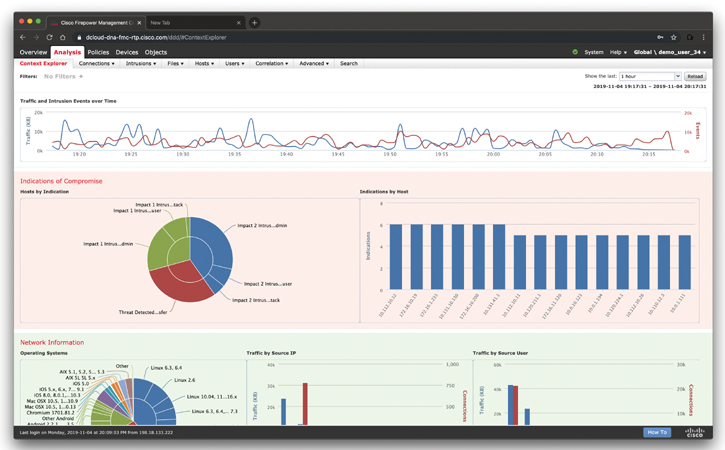
Figure 7-3 The Cisco FMC Content Explorer
The Network File Trajectory feature maps how hosts transferred files, including malware files, across your network. A trajectory charts file transfer data, the disposition of the file, and whether a file transfer was blocked or the file was quarantined. You can determine which hosts and users may have transferred malware, which hosts are at risk, and observe file transfer trends.
You can track the transmission of any file with a Cisco cloud-assigned disposition. The system can use information related to detecting and blocking malware from both AMP for Networks and AMP for Endpoints to build the trajectory. Figure 7-4 shows an example of the Network File Trajectory screen in the Cisco FMC, showing how a piece of malware infected different hosts across the network.
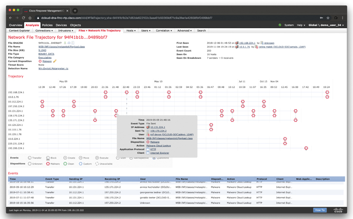
Figure 7-4 The Cisco FMC Network File Trajectory
Exploring the Cisco Firepower Device Manager (FDM)
The Cisco Firepower Device Manager (FDM) is used to configure small Cisco FTD deployments. To access the Cisco FDM, you just need to point your browser at the firewall in order to configure and manage the device.
Figure 7-5 shows the Cisco FDM Device Setup Wizard.
Figure 7-6 shows the Cisco FDM main dashboard. The Cisco FDM main dashboard includes information about the configured interfaces, configured routes, and updates (Geolocation, Rules, Vulnerability Database [VDB], Security Intelligence Feeds, and so on). It also provides information about the smart licenses that are enabled on the system, backup and restore configuration, and troubleshooting information.
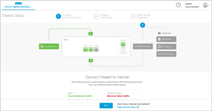
Figure 7-5 The Cisco FDM Device Setup Wizard
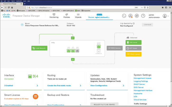
Figure 7-6 The Cisco FDM Main Dashboard
The Cisco FDM allows you to configure network address translation (NAT), access control, and intrusion policies. Figure 7-7 shows the manual NAT configuration in the Security Policies screen of the Cisco FDM. NAT will be discussed in detail later in this chapter.
Figure 7-8 shows an example of a NAT rule in the Cisco FDM.

Figure 7-7 Manual NAT Configuration in the Cisco FDM Security Policies Screen

Figure 7-8 Example of a NAT Rule in the Cisco FDM
Figure 7-9 shows an example of how an access control rule is applied to the inside and outside security zones.
A security zone is a collection of one or more inline, passive, switched, or routed interfaces (or ASA interfaces) that you can use to manage and classify traffic in different policies. Interfaces in a single zone could span multiple devices. Furthermore, you can also enable multiple zones on a single device to segment your network and apply different policies.
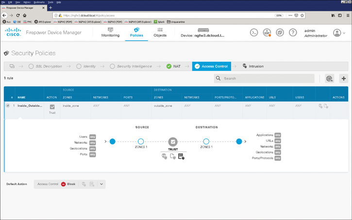
Figure 7-9 Access Control Rule Configured to Protect Traffic in Different Security Zones
You can also use zones in different places in the system’s web interface. This includes access control policies, network discovery rules, and event searches—for instance, to configure an access control rule that applies only to a specific source or destination zone or to restrict network discovery to traffic to or from a specific zone.
Cisco FTD creates security zones upon device registration, depending on the detection mode you selected for the device during its initial configuration. For instance, Cisco FTD creates a passive zone in passive deployments, while in inline deployments, Cisco FTD creates External and Internal zones. You can also create security zones when you are configuring interfaces on a Cisco Firepower device.
Figure 7-10 shows the configuration of a source- and destination-based access control rule.
Figure 7-11 shows the configuration of an application-based access control rule.
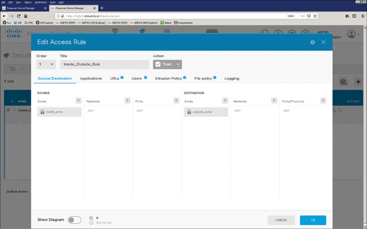
Figure 7-10 A Source- and Destination-Based Access Control Rule

Figure 7-11 An Application-Based Access Control Rule
Cisco Defense Orchestrator
The Cisco Defense Orchestrator (CDO) is a solution that allows you to manage your firewalls from the cloud. You can write a policy once and enforce it consistently across multiple Cisco ASA and Cisco FTD devices. In addition, you can compare, filter, edit, and create new policies, all from a central point (the cloud). The Cisco Defense Orchestrator allows you to analyze access control policies and objects to identify errors and inconsistencies. You can also create standard policy templates that give you consistent, effective protection across your enterprise environment.
Figure 7-12 shows the Cisco Defense Orchestrator main dashboard.
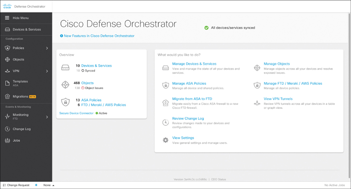
Figure 7-12 The Cisco Defense Orchestrator Main Dashboard
Figure 7-13 shows examples of Cisco ASA policies configured in Cisco Defense Orchestrator.

Figure 7-13 Examples of Cisco ASA Policies Configured in Cisco Defense Orchestrator
The Cisco Defense Orchestrator can also manage and analyze Cisco FTD, Meraki security devices, and virtual firewalls in AWS. Figure 7-14 shows examples of policies of Cisco FTD, Meraki security devices, and virtual firewalls in AWS.
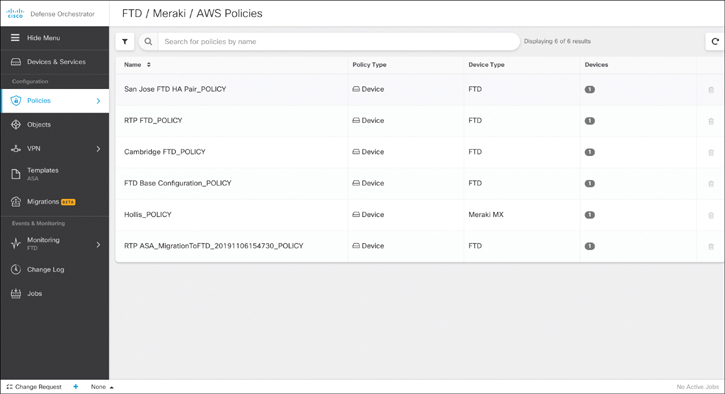
Figure 7-14 Examples of Policies of Cisco FTD, Meraki Security Devices, and Virtual Firewalls in AWS
Figure 7-15 shows a detailed example of Cisco FTD policies in Cisco Defense Orchestrator.

Figure 7-15 A Detailed Example of Cisco FTD Policies in Cisco Defense Orchestrator
Comparing Network Security Solutions That Provide Firewall Capabilities
There are different Cisco solutions that provide intrusion prevention and firewall capabilities. You already learned a few details about the Cisco ASA and the Cisco Firepower next-generation firewalls (NGFW). Next-generation firewalls also provide intrusion prevention capabilities. On the other hand, there is one more firewall solution: Cisco IOS Zone-Based Firewall (ZBFW). The Cisco IOS Zone-Based Firewall is a stateful firewall used in Cisco IOS devices. ZBFW is the successor of the legacy IOS firewall or the Context-Based Access Control (CBAC) feature.
Cisco ASA and FTD devices are considered dedicated firewall devices; however, Cisco integrated the firewall functionality into the router, which in fact will make the firewall a cost-effective device. The ZBFW includes features that are not available in CBAC (including the assignment of the router interfaces to different security zones to control IP traffic). Zone-based firewalls can also be implemented in an SD-WAN solution.
In an SD-WAN configuration, zone deployments and configurations include the following components:
Source zone: A group of VPNs where the data traffic flows originate. A VPN can be part of only one Source zone.
Destination zone: A grouping of VPNs where the data traffic flows terminate. A VPN can be part of only one Destination zone.
Firewall policy: A security policy, similar to a localized security policy, that defines the conditions that the data traffic flow from the source zone must match to allow the flow to continue to the destination zone. Firewall policies can match IP prefixes, IP ports, the protocols TCP, UDP, and ICMP, and applications. Matching flows for prefixes, ports, and protocols can be accepted or dropped, and the packet headers can be logged. Nonmatching flows are dropped by default. Matching applications can only be denied.
Zone pair: A container that associates a source zone with a destination zone and applies a firewall policy to the traffic that flows between the two zones.
Matching flows that are accepted can be processed in two different ways:
Inspect: The packet’s header can be inspected to determine its source address and port.
Pass: The packet can pass to the destination zone without the packet’s header being inspected at all.
In ZBFW deployments a zone must be configured before interfaces can be assigned to the zone. In addition, an interface can be assigned to only one security zone. All traffic to and from a given interface in a device with ZBFW configured is implicitly blocked when the interface is assigned to a zone, except traffic to and from other interfaces in the same zone as well as traffic to any interface on the router (that is, the self-zone). IP traffic is implicitly allowed to flow by default among interfaces that are members of the same zone. When you configure ZBFW, in order to permit traffic to and from a zone member interface, a policy allowing or inspecting traffic must be configured between that zone and any other zone.
The self-zone is the only exception to the default “deny all” policy. All traffic to any router interface is allowed until traffic is explicitly denied. Traffic cannot flow between a zone member interface and any interface that is not a zone member. Pass, inspect, and drop actions can only be applied between two zones.
Deployment Modes of Network Security Solutions and Architectures That Provide Firewall Capabilities
Cisco ASA and Cisco FTD devices can be configured in different deployment modes. Let’s start with the Cisco ASA. The Cisco ASA protects an internal (or protected) network from external threats sourced through (or from) an untrusted interface. Each interface is assigned a name to designate its role on the network. The most secure network is typically labeled as the inside network, whereas the least secure network is designated as the outside network. For semi-trusted networks, you can define them as demilitarized zones (DMZ) or any logical interface name. You must use the interface name to set up the configuration features that are linked to an interface.
The Cisco ASA also uses the concept of assigning security levels to the interfaces. The higher the security level, the more protected the interface. Consequently, the security level is used to reflect the level of trust of this interface with respect to the level of trust of another interface on the Cisco ASA. The security level can be between 0 and 100. Therefore, the safest network is placed behind the interface with a security level of 100, whereas the least protected network is placed behind an interface with a security level of 0. A DMZ interface should be assigned a security level between 0 and 100.
When an interface is configured with a nameif command, the Cisco ASA automatically assigns a preconfigured security level. If an interface is configured with the name “inside,” the Cisco ASA assigns a security level of 100. For all the other interface names, the Cisco ASA assigns a security level of 0.
Cisco ASA enables you to assign the same security level to more than one interface. If communication is required between the hosts on interfaces at the same security level, use the same-security-traffic permit inter-interface global configuration command. Additionally, if an interface is not assigned a security level, it does not respond at the network layer.
The most important parameter under the interface configuration is the assignment of an IP address. This is required if an interface is to be used to pass traffic in a Layer 3 firewall, also known as routed mode. An address can be either statically or dynamically assigned. For a static IP address, configure an IP address and its respective subnet mask.
The Cisco ASA also supports interface address assignment through a Dynamic Host Configuration Protocol (DHCP) server. Assigning an address via DHCP is a preferred method if an ISP dynamically allocates an IP address to the outside interface. You can also inform the Cisco ASA to use the DHCP server’s specified default gateway as the default route if the Obtain Default Route Using DHCP option is enabled.
Routed vs. Transparent Firewalls
Traditionally, network firewalls have been deployed to filter traffic passing through them. These firewalls usually examine the upper-layer headers (Layer 3 or above) and the data payload in the packets. The packets are then either allowed or dropped based on the configured access control lists (ACLs). These firewalls, commonly referred as routed firewalls, segregate protected networks from unprotected ones by acting as an extra hop in the network design. They route packets from one IP subnet to another subnet by using the Layer 3 routing table. In most cases, these firewalls translate addresses to protect the original IP addressing scheme used in the network.
If a Cisco ASA is deployed in transparent mode, the IP address is assigned in global configuration mode or on a bridge virtual interface (BVI), depending on the version of code. Assigning an interface address through DHCP is not supported if used with failover.
Routed firewalls do not provide a way to filter packets that traverse from one host to another in the same LAN segment. The Layer 3 firewalls require a new network segment to be created when they are inserted into a network, which requires quite a bit of planning, network downtime, and reconfiguration of network devices. To avoid these issues, stealth or transparent firewalls have been developed to provide LAN-based protection. You can place a transparent firewall between the LAN and the next-hop Layer 3 device (usually a router) without having to readdress the network devices.
By using transparent firewalls (also known as Layer 2 firewalls or stealth firewalls), you can optionally inspect Layer 2 traffic and filter unwanted traffic. Figure 7-16 shows SecretCorp’s network running a transparent firewall. SecretCorp.org (aka SecretCorp) wants to inspect all traffic before it hits the default gateway. When the host 192.168.10.2 sends traffic destined to www.cisco.com, the firewall makes sure that the packets are allowed before passing them to the default gateway, 192.168.10.1. In this case, the default gateway router is responsible for translating the 192.168.10.0/27 subnet to 209.165.200.224/27 to reach the Internet.

Figure 7-16 A Firewall Configured in Transparent (Layer 2) Mode
Security Contexts
Security contexts enable a physical firewall to be partitioned into multiple standalone firewalls. Each standalone firewall acts and behaves as an independent entity with its own configuration, interfaces, security policies, routing table, and administrators. In Cisco ASA, these “virtual” firewalls are known as security contexts.
The following are some sample scenarios in which security contexts are useful in network deployments:
You act as a service provider and you want to provide firewall services to customers; however, you do not want to purchase additional physical firewalls for each client.
You manage an educational institution and you want to segregate student networks from faculty networks for improved security while using one physical security appliance.
You administer a large enterprise with different departmental groups, and each department wants to implement its own security policies.
You have overlapping networks in your organization and you want to provide firewall services to all those networks without changing the addressing scheme.
You currently manage many physical firewalls and you want to integrate security policies from all firewalls into one physical firewall.
You manage a data center environment and you want to provide end-to-end virtualization to reduce operational costs and increase efficiency.
A transparent firewall can coexist with these modes to provide a great deal of flexibility for network deployments. You can set the Cisco ASA firewall mode (either routed or transparent) per context in multimode.
Single-Mode Transparent Firewalls
In a single-mode transparent firewall (SMTF), the Cisco ASA acts as a secured bridge that switches traffic from one interface to another. You do not configure IP addresses on either the inside interface or the outside interface. Rather, you must specify a global IP address that is primarily used for management purposes—Telnet and Secure Shell (SSH). The transparent firewall also uses the management IP address when it needs to source packets such as ARP requests and syslog messages.
This is the simplest form of configuration because it does not require configuration of security contexts, dynamic routing protocols, or interface-specific addresses. The configuration only requires you to define the ACLs, inspection rules, and optionally NAT policies to determine which traffic is allowed. The next section talks about how a packet flows through an SMTF.
The admin context provides connectivity to the network resources such as the AAA or syslog server. It is recommended that you assign the management interface(s) of the Cisco ASA to the admin context. You must assign IP addresses to the allocated interfaces as you would with any other context. The Cisco ASA uses the configured IP addresses to retrieve configurations for other contexts if those configurations are stored on a network share, or to provide remote management of the device through SSH or Telnet. A system administrator with access to the admin context can switch into the other contexts to manage them. The Cisco ASA also uses the admin context to send the syslog messages that relate to the physical system. Essentially, the admin context is also used by the system context to perform functions that may involve Layer 2 or Layer 3 functionality. This includes file copying and management functionality such as generating syslogs or SNMP traps.
Contexts include the admin and user contexts.
The admin context must be created before you define other contexts. Additionally, it must reside on the local disk. You can designate a new admin context at any time by using the admin-context command.
When a Cisco ASA is converted from single mode to multiple mode, the network-related configuration of the single-mode Cisco ASA is saved into the admin context. The security appliance, by default, names this context admin.
The admin context configuration is similar to a user context. Aside from its relationship to the system execution space, it can be used as a regular context. However, using it as a regular context is not recommended because of its system significance.
Each user or customer context acts as a virtual firewall with its own configuration that contains almost all the options that are available in a standalone firewall. A virtual firewall supports a number of features that are available in a standalone firewall, such as the following:
IPS functionality
Dynamic routing
Packet filtering
Network address translation (NAT)
Site-to-site VPN
IPv6 and device management
When packets traverse the Cisco ASA in multiple-context mode, they are classified and forwarded to the correct context. One of the benefits of using virtualization is the sharing of resources, such as the physical interfaces between the security contexts.
This brings up the question of how the Cisco ASA should determine which security context packets should be processed when packets are received on an interface allocated to multiple contexts. Cisco ASA makes this determination through the use of a packet classifier, identifying packets at the ingress interface. The Cisco ASA designates an assortment of packet-classifying criteria to identify the correct security context before forwarding packets. After packets are sent to a security context, they are processed based on the security policies configured in that context.
Cisco ASA uses a number of criteria to classify packets before forwarding traffic to the correct security context. Depending on how you want to implement a security appliance, the packet classifying criteria could be different. You can deploy the security contexts in either a shared interface environment or in a non-shared interface environment.
If all contexts in the Cisco ASA use unique physical or logical sub-interfaces, the packet classification becomes easier because the Cisco ASA labels these packets based on the source interface.
The Cisco ASA enables you to share one or more interfaces between the security contexts. In this deployment model, the Cisco ASA can use either a destination IP address or a unique MAC address on the Cisco ASA to classify the packet to the correct context.
If you share an interface between multiple security contexts, then, depending on the version, the interface may use the same MAC address across all virtual firewalls. With this approach, the ingress packets on the physical interface, regardless of the security context, have the same MAC address. When packets are received by the Cisco ASA for a particular security context, the classifier does not know to which security context to send the packets.
To address this challenge, the classifier uses the packet’s destination IP address to identify which security context should receive packets in a shared environment. However, the firewall cannot classify traffic based on the routing table of the contexts because multiple mode allows for overlapping networks, and the routing table might be the same for two contexts. The classifier, in this case, relies strictly on the NAT table of each security context to learn about the subnets located behind each security context.
In a multimode transparent firewall (MMTF), Cisco ASA acts in a similar fashion to how it performs in single mode, with two major exceptions:
Packets are handled in different contexts. Because each context acts and behaves as an independent entity, you must configure an IP address to the bridge virtual interface (BVI) in each context for administration and management purposes.
An interface cannot be shared between multiple contexts in this mode.
Surveying the Cisco FTD Deployment Modes
Cisco FTD devices can be configured in routed and transparent mode, just like the Cisco ASA devices.
Figure 7-17 shows a Cisco FTD in routed mode.
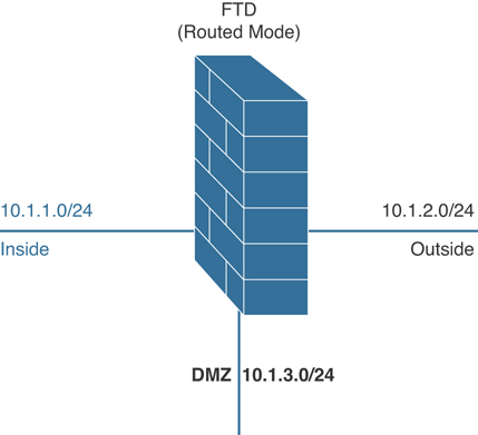
Figure 7-17 Cisco FTD in Routed Mode
Figure 7-18 shows a Cisco FTD in transparent (Layer 2) mode.

Figure 7-18 Cisco FTD in Transparent (Layer 2) Mode
Cisco FTD Interface Modes
Cisco FTD devices can also operate as next-generation firewalls and next-generation intrusion prevention devices in different interfaces. NGFW inherits operational modes from ASA and adds Firepower features. NGIPS operates as standalone Firepower with limited ASA data plane functionality.
You can configure IPS-only passive interfaces, passive ERSPAN interfaces, and inline sets in Cisco FTD devices. When interfaces are configured in IPS-only mode, they bypass many firewall checks and only support IPS (intrusion) security policies. Typically, you deploy IPS-only interfaces if you have a separate firewall protecting these interfaces and do not want the overhead of firewall functions.
Inline sets and passive interfaces are only supported on physical interfaces and EtherChannels. Inline sets cannot use redundant interfaces or VLANs. Inline sets and passive interfaces are supported in intra-chassis and inter-chassis clustering.
Bidirectional Forwarding Detection (BFD) echo packets are not allowed through the FTD when using inline sets. If there are two neighbors on either side of the FTD running BFD, then the FTD will drop BFD echo packets because they have the same source and destination IP address.
Figure 7-19 shows the Cisco FTD deployment modes, and Figure 7-20 shows the Cisco FTD interface modes.
Cisco FTD interface modes can be mixed on a single device. Figure 7-21 demonstrates intra-BVI communication. In this mode, no additional routing is needed, as long as the destination IP address is in the same subnet as the BVI interface.
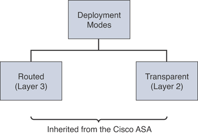
Figure 7-19 Cisco FTD Deployment Modes
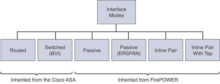
Figure 7-20 Cisco FTD Interface Modes

Figure 7-21 Cisco FTD Intra-BVI Communication
Figure 7-22 demonstrates inter-BVI communication. In this mode, no additional routing is needed, as long as the destination IP address is in the directly connected subnet as the BVI interfaces.

Figure 7-22 Cisco FTD Inter-BVI Communication
Figure 7-23 demonstrates traffic between a regular routed (Layer 3) interface and a BVI.

Figure 7-23 Traffic Between a Regular Routed (Layer 3) Interface and a BVI
Inline Pair
As in legacy IPS, Cisco NGFW and Cisco NGIPS can operate in two main modes: inline and passive (monitoring) mode. Inline mode is used for prevention. Inline devices can be placed between two assets that communicate or at a point that aggregates traffic from various sources—between a switch and a firewall or between a router and a switch—to block and mitigate threats. Two of the interfaces of the device are used in an inline pair for traffic to enter and exit the device after being inspected. Based on the configured policies, traffic can be dropped, allowed, or reset.
The caveat with inline interfaces is that in the event of a software failure or a loss of power, all traffic is dropped. The fail-open capability can be used to allow traffic to bypass the device rules and policies, and consequently, avoid traffic loss. Fail-open should not be used when the security policy doesn’t allow traffic to go unaccounted for or uninspected.
Inline mode offers two more modes of operation: routed and switched. In routed mode, the device operates at Layer 3, as a router would. As you learned earlier in this chapter, in switched mode, the device is in transparent mode and doesn’t show in the path as a Layer 3 hop. It uses two interfaces in a VLAN pair and bridges them together.
Figure 7-24 shows a Cisco FTD configured with 10 interfaces. There are two inline sets. One of the inline sets includes three pairs of interfaces, and the other includes two pairs of interfaces. You can configure the Cisco FTD in an inline NGIPS deployment or transparently on a network segment by binding two ports together. This allows the Cisco FTD to be deployed without the need to perform additional configuration in adjacent network devices. Cisco FTD inline interfaces receive all traffic unconditionally. Furthermore, all the traffic received on inline interfaces is retransmitted out of an inline set unless explicitly dropped. When you add multiple inline interface pairs to the same inline interface set, the Cisco FTD categorizes the inbound and outbound traffic as part of the same traffic flow. If you configure passive interfaces (promiscuous mode only), this traffic categorization is achieved by including the interface pairs in the same security zone.
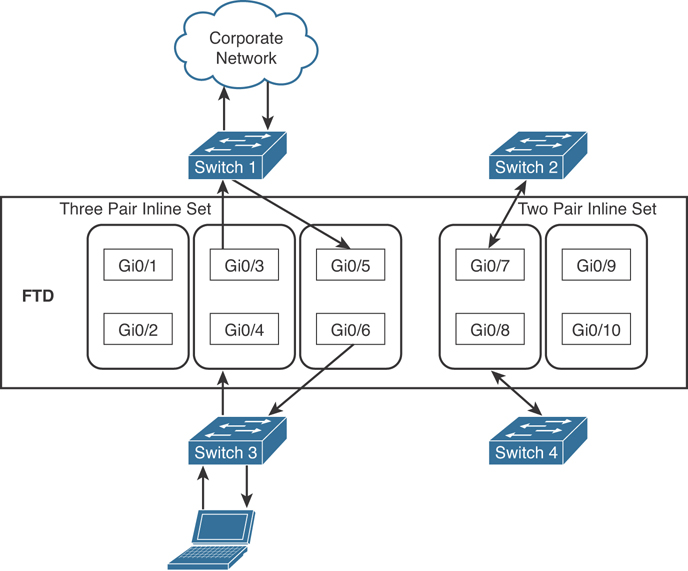
Figure 7-24 Example of Multiple Inline Interface Sets
Inline Pair with Tap
You can also configure an inline pair with a “tap,” where you have two physical interfaces internally bridged. A few firewall engine checks are applied along with full Snort engine checks to a copy of the actual traffic. Most of the traditional firewall features, such as NAT, routing, and ACLs, are not available for flows going through an inline pair. Inline pair with tap is supported in routed or transparent deployment modes.
Figure 7-25 shows an example of an inline pair with tap configuration.
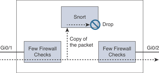
Figure 7-25 Example of Inline Pair with Tap
Passive Mode
Monitoring (passive) mode is the mode where the Cisco NGFW or NGIPS device does not usually prevent attacks. The device uses one interface to silently inspect traffic and identify malicious activity without interrupting traffic flow. It is usually connected to a switch’s span port, a mirrored port, or a network tap interface. Even though in monitoring mode the device doesn’t block traffic, there is an option to reset malicious connections, but that should not be considered as a mitigation mechanism as it can’t guarantee attack prevention. Passive mode is supported in routed or transparent deployment modes. A few firewall engine checks and full Snort engine checks are applied to a copy of the IP traffic.
Figure 7-26 shows an example of a passive mode deployment.
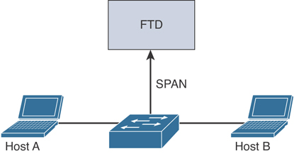
Figure 7-26 Example of Passive Mode Deployment
Passive with ERSPAN Mode
You can configure one physical interface operating as a sniffer—very similar to a traditional remote intrusion detection system (IDS). A Generic Routing Encapsulation (GRE) tunnel between the capture point and the Cisco FTD carries the packets to be inspected. An example of a passive with ERSPAN deployment mode is illustrated in Figure 7-27. Passive with ERSPAN is supported only in routed deployment mode.

Figure 7-27 Example of Passive ERSPAN Deployment Mode
Additional Cisco FTD Deployment Design Considerations
Table 7-2 provides additional design considerations.
Table 7-2 Deployment Mode Design Considerations
Design Consideration |
Recommendation/Comment |
Management |
Local (FDM) or Central (FMC). FMC recommended for multiple appliances, enhanced visual analysis, central configuration, alerting, and reporting. |
Standalone or resilient |
Resilient recommended. Has impact on the number of interfaces required. |
Link speed(s) / types |
Up/downstream speeds, internal/DMZ connections. |
Routed or Transparent mode |
Routed mode recommended for Edge. Transparent/NGIPS only for customers who already have a third-party firewall. |
Number of interfaces |
Internal, External, HA, or DMZs. |
Traffic profile |
Clear or Encrypted, Streaming, Hosting Services. |
Application control |
Typical requirement at the edge. Opportunity to discuss OpenAppID. |
URL filtering |
Good for remote/branch locations. Central/HQ may already have provision. |
Deep inspection |
Cisco strength. Industry-leading protection. Can have an impact on performance, so size accordingly. |
File and malware protection |
Cisco differentiator. Advanced Malware Protection (AMP) can enhance existing AMP solutions or lead to upsell or further expansion. |
High Availability and Clustering
You can deploy Cisco next-generation firewalls in high-availability (failover) mode or in a cluster. Let’s start with failover. High availability (failover) is supported in Cisco ASA and Cisco FTD devices. When you configure failover, you must have two identical Cisco FTD or Cisco ASA devices connected to each other through a dedicated failover link. You can also configure a state link (to pass stateful firewall information between both devices).
Cisco ASA supports Active-Standby failover, where one unit is the active unit and passes traffic. Cisco ASA also supports Active-Active failover, where both units are passing traffic at the same time. Cisco FTD supports only Active-Standby failover. Figure 7-28 illustrates the concept of Active-Standby failover.

Figure 7-28 Active-Standby Failover
In Figure 7-28, two Cisco FTD devices are deployed. The standby FTD (FTD 2) does not actively pass traffic; however, it synchronizes configuration and other state information from the active unit via the state link. When a failover occurs, the active FTD device (FTD 1) fails over to the standby device (FTD 2), which then becomes active.
The failover and the stateful failover links are dedicated connections between the two units. Cisco recommends using the same interface on both devices in a failover link or a stateful link. Configuring two separate interfaces on each of the devices—one for failover and another for stateful link—is also recommended. For instance, if Gigabit Ethernet 1 is used for the failover link in the first Cisco FTD device, then you should use the same interface (Gigabit Ethernet 1) in the second participant device. The same goes for the stateful link. If you have Gigabit Ethernet 2 for the stateful link, you should match the same interface in the second Cisco FTD device (that is, Gigabit Ethernet 2 in FTD 2).
Both of the devices in the Cisco FTD failover pair constantly communicate over the failover link to determine the operating status of each device. In a failover configuration, the health of the active unit (hardware failures, interfaces, software, and so on) is monitored to determine if specific failover conditions are met, and then, subsequently, failover occurs.
The following is the type of information being exchanged over the failover link:
The firewall state (active or standby)
Hello messages (keepalives)
Network link status
MAC address exchange
Configuration replication and synchronization
The following are requirements for failover configurations:
The two participant devices must be configured in the same firewall mode (for example, routed or transparent).
The two participant devices must be running the same software version.
You can configure different Cisco FTD devices in groups (or domains) in the Cisco FMC. Devices configured for failover must be in the same domain or group on the Cisco FMC.
The two participant devices must have the same Network Time Protocol (NTP) configuration (and time must be synchronized).
Failover participant devices must be fully deployed with no uncommitted changes in the Cisco FMC.
DHCP or PPPoE must not be configured on any of their interfaces.
Additionally, Cisco FTD devices configured for failover must have the same licenses. When you configure failover, the Cisco FMC releases any unnecessary licenses assigned to the standby device and replaces them with identical licenses assigned to the active and standby device.
The stateful failover link (also known as the state link) is used to pass connection state information. As a best practice, make sure that the bandwidth of the stateful failover link is at least the same bandwidth as the data interfaces.
Clustering
Clustering lets you group multiple Cisco FTD units together as a single logical device. Clustering is supported on the Cisco Firepower 9300 and the Cisco Firepower 4100 series. Figure 7-29 illustrates a cluster of four FTD devices connected to two switches, providing all the convenience of “a single logical entity” (management and integration into a network) while achieving the increased throughput and redundancy of multiple devices.

Figure 7-29 FTD Cluster Example
The cluster in Figure 7-29 consists of multiple devices acting as a single logical unit. When you deploy a cluster, the FTD devices create a cluster-control link (by default, port-channel 48) for unit-to-unit communication. You can also configure intra-chassis clustering in the Cisco Firepower 9300. The intra-chassis cluster link utilizes the Firepower 9300 backplane for cluster communications. For inter-chassis clustering, you need to manually assign one or more physical interfaces in an EtherChannel configuration for communications between chassis. When you deploy the cluster, the Firepower chassis supervisor pushes a minimal bootstrap configuration to each unit that includes the cluster name and cluster control link interface settings.
In the example illustrated in Figure 7-29, the FTD cluster members work together sharing the security policy and traffic flows. FTD 1 is the master unit. The master unit in a cluster configuration is determined automatically, and all other cluster members are considered “slave units.” The master is either the first unit joining the cluster or based on a configured priority. You must perform all configuration on the master unit only; the configuration is then replicated to the other units. A new master is elected only upon a departure of the existing one. The master unit handles all management and centralized functions.
The Cisco FTD cluster automatically creates the cluster control link using the port-channel 48 interface. Both data and control traffic are sent over the cluster control link. The cluster control link should be sized to match the expected throughput of each cluster participant (each Cisco FTD device). This is done to make sure that the cluster-control link can handle the worst-case scenarios of data throughput. The cluster control link traffic includes state update and forwarded packets. The amount of traffic at any given time on the cluster control link varies. The amount of forwarded traffic depends on the load-balancing efficacy or whether there is a lot of traffic for centralized features.
Figure 7-30 demonstrates the Cisco FTD cluster unit state transition.

Figure 7-30 Cisco FTD Cluster Unit State Transition
The following are the steps illustrated in Figure 7-30:
After the unit boots, it looks for a master over the cluster control link.
If there are no master units, it waits 45 seconds before assuming the master role. If a master already exists, it becomes a slave and the configuration is synchronized.
If there is a synchronization or health issue, the unit is considered disabled in the cluster.
Implementing Access Control
Access control is the crossroads for all traffic traversing the firewall. In the Cisco ASA, access control is done by configuring access control lists (ACLs). The Cisco FTD supports different access control policies that extend beyond traditional ACLs. The following sections cover how to implement access control lists in Cisco ASA and how access control is done in Cisco FTD deployments.
Implementing Access Control Lists in Cisco ASA
An ACL is a collection of security rules or policies that allows or denies packets after looking at the packet headers and other attributes. Each permit or deny statement in the ACL is referred to as an access control entry (ACE). These ACEs classify packets by inspecting Layer 2 through Layer 7 headers for a number of parameters, including the following:
Layer 2 protocol information such as EtherTypes
Layer 3 protocol information such as ICMP, TCP, or UDP
Layer 3 header information such as source and destination IP addresses
Layer 4 header information such as source and destination TCP or UDP ports
Layer 7 information such as application and system service calls
After an ACL has been properly configured, apply it to an interface to filter traffic. The Cisco ASA filters packets in both the inbound and outbound direction on an interface. When an inbound ACL is applied to an interface, the Cisco ASA analyzes packets against the ACEs after receiving them. If a packet is permitted by the ACL, the firewall continues to process the packet and eventually passes the packet out the egress interface.
ACLs can also be configured outbound. When an outbound ACL is configured, the Cisco ASA inspects the packets that are exiting out of the specific interface, but not on incoming packets.
ACLs include a five-tuple:
Source IP address (or subnet)
Source port
Destination IP address (or subnet)
Destination port
Protocol
ACLs are also identified by either a number or a name. Figure 7-31 shows an example of an ACL allowing HTTPS (TCP port 443) traffic from 10.2.2.2 to 10.1.1.2.
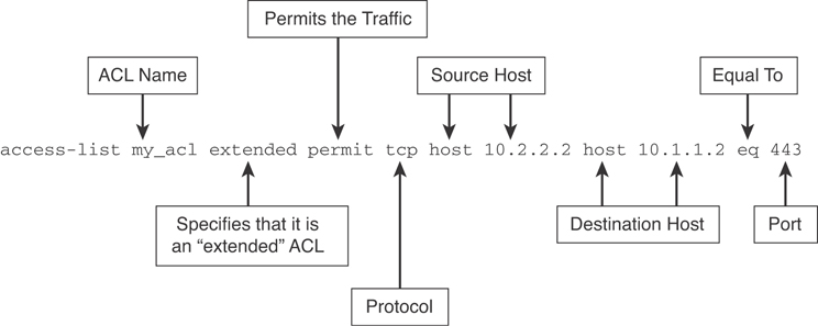
Figure 7-31 An Access Control List Example in the Cisco ASA
If a packet is denied by the ACL, the Cisco ASA discards the packet and generates a syslog message indicating that such an event has occurred. In Figure 7-32, the Cisco ASA administrator has configured an ACL that permits only HTTP traffic destined for 10.1.1.2 and has applied the ACL inbound on the outside interface. All other traffic is dropped at the outside interface by the Cisco ASA.
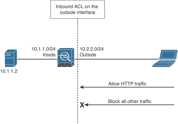
Figure 7-32 Inbound ACL Example
If an outbound ACL is applied on an interface, the Cisco ASA processes the packets by sending them through the different processes (NAT, QoS, and VPN) and then applies the configured ACEs before transmitting the packets out on the wire. The Cisco ASA transmits the packets only if they are allowed to go out by the outbound ACL on that interface. If the packets are denied by any one of the ACEs, the Cisco ASA discards the packets and generates a syslog message indicating that such an event has occurred. In Figure 7-33, the Cisco ASA administrator has configured an ACL that permits only HTTP traffic destined for 10.1.1.2 and has applied the ACL outbound on the inside interface. All other traffic gets dropped at the interface by the Cisco ASA.
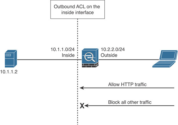
Figure 7-33 Outbound ACL Example
The Cisco ASA also allows you to define a global ACL. All inbound traffic, regardless of the interface, is subject to inspection by a global ACL. If both an inbound interface ACL and a global ACL are configured, the Cisco ASA applies the interface ACL first, then the global ACL, and eventually the implicit deny in case there is no specific match.
So, should you use an interface ACL or a global ACL? An interface-specific ACL gives you more control to filter traffic if you know which interface it enters or leaves. You can apply an interface ACL in both inbound and outbound directions. However, if you have multiple interfaces connected to a network and you are not sure where packets may enter into the security appliance, consider applying a global ACL.
The following are some important characteristics of an ACL:
When a new ACE is added to an existing ACL, it is appended to the end of the ACL, unless a specific line number is specified.
When a packet enters the security appliance, the ACEs are evaluated in sequential order. Hence, the order of an ACE is critical. For example, if you have an ACE that allows all IP traffic to pass through, and then you create another ACE to block all IP traffic, the packets are never evaluated against the second ACE because all packets match the first ACE.
There is an implicit deny at the end of all ACLs. If a packet is not matched against a configured ACE, it is dropped and a syslog with message ID of 106023 is generated.
By default, you do not need to define an ACE to permit traffic from a high-security-level interface to a low-security-level interface. However, if you want to restrict traffic flows from a high-security-level interface destined to a low-security-level interface, you can define an ACL. If you configure an ACL for traffic originating from a high-security-level interface to a low-security-level interface, it disables the implicit permit from that interface. All traffic is now subject to the entries defined in that ACL.
An ACL must explicitly permit traffic traversing the Cisco ASA from a lower- to a higher-security-level interface of the firewall. The ACL must be applied to the lower-security-level interface or globally.
The ACLs (extended or IPv6) must be applied to an interface to filter traffic that is passing through the security appliance. Beginning with Cisco ASA Software version 9.0(1), you can use a single ACL to filter both IPv4 and IPv6 traffic.
You can bind one extended ACL and one EtherType ACL in each direction of an interface at the same time.
You can apply the same ACL to multiple interfaces. However, doing so is not considered to be a good security practice because correlating ACL hit counts to a specific interface’s traffic would be impossible.
You can use ACLs to control both traffic through the Cisco ASA and traffic to the security appliance. The ACLs that control traffic to the appliance are applied differently than ACLs that filter traffic through the appliance.
When TCP or UDP traffic flows through the security appliance, the return traffic is automatically allowed to pass through because the connections are bidirectional.
Other protocols such as ICMP are considered unidirectional connections, so you need to allow ACL entries in both directions. However, when you enable the ICMP inspection engine, the inspection engine keeps track of the ICMP messages and then allows replies (such as ping packets).
The Cisco ASA supports four different types of ACLs to provide a flexible and scalable solution to filter unauthorized packets into the network:
Standard ACLs
Extended ACLs (Figure 7-31 illustrated an example of an extended ACL)
EtherType ACLs
Webtype ACLs
Standard ACLs are used to identify packets based on their destination IP addresses. These ACLs can be used in scenarios such as split tunneling for the remote-access VPN tunnels and route redistribution within route maps. These ACLs, however, cannot be applied to an interface for filtering traffic. A standard ACL can be used only if the Cisco ASA is running in routed mode, by acting as an extra Layer 3 hop in the network.
Extended ACLs, the most commonly deployed ACLs, classify packets based on the following attributes:
Source and destination IP addresses
Layer 3 protocols
Source and/or destination TCP and UDP ports
Destination ICMP type for ICMP packets
User identity attributes such as Active Directory (AD) username or group membership
An extended ACL can be used for interface packet filtering, QoS packet classification, packet identification for NAT and VPN encryption, and a number of other features. These ACLs can be set up on the Cisco ASA in both routed mode and transparent firewall mode.
EtherType ACLs are used to filter IP- and non-IP-based traffic by checking the Ethernet type code field in the Layer 2 header. IP-based traffic uses an Ethernet type code value of 0x800, whereas Novell IPX uses 0x8137 or 0x8138, depending on the Netware version. An EtherType ACL can be configured only if the Cisco ASA is running in transparent mode.
Like all ACLs, the EtherType ACL has an implicit deny at the end of it. However, this implicit deny does not affect the IP traffic passing through the security appliance. As a result, you can apply both EtherType and extended ACLs to each direction of an interface. If you configure an explicit deny at the end of an EtherType ACL, it blocks IP traffic even if an extended ACL allows those packets to pass through.
A Webtype ACL allows Cisco ASA administrators to restrict traffic coming through the SSL VPN tunnels. In cases where a Webtype ACL is defined but there is no match for a packet, the default behavior is to drop the packet because of the implicit deny. On the other hand, if no ACL is defined, the Cisco ASA allows traffic to pass through it.
Access control lists on a Cisco ASA can be used to filter out not only packets passing through the appliance but also packets destined to the appliance.
Through-the-box traffic filtering refers to traffic that is passing through the security appliances from one interface to another interface. As mentioned earlier, an ACL is a collection of access control entries. When new connections are being established through the security appliance, they are subjected to the ACL configured on the interfaces that would pass traffic. The packets are either allowed or dropped based on the configured action on each ACE. An ACE can be as simple as permitting all IP traffic from one network to another, or as complicated as permitting or denying traffic originating from a unique source IP address on a particular port destined to a specific port on the destination address in a specific time period.
The Implementing and Operating Cisco Security Core Technologies (SCOR 350-701) exam does not cover detailed configuration and troubleshooting. The CCNP Security concentration exams and the CCIE Security exam focus on configuration and troubleshooting. However, you may find some questions with high-level configuration scenarios in the SCOR exam. The following are a few examples of ACL configurations to enhance the learning.
The topology illustrated in Figure 7-34 is used in the next examples.
Cisco ASA protects the protected network from external threats. Each interface is assigned a name to designate its role on the network. The most secure network is typically labeled as the inside network, whereas the least secure network is designated as the outside network. For semi-trusted networks, you can define them as demilitarized zones (DMZ) or any logical interface name. You must use the interface name to set up the configuration features that are linked to an interface.
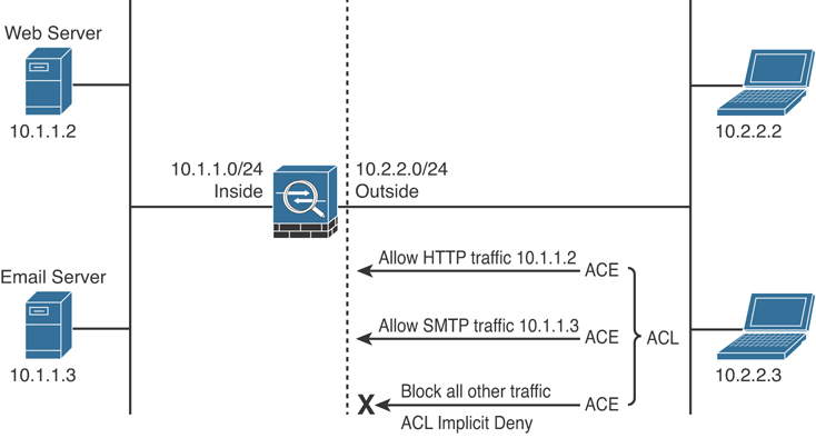
Figure 7-34 Cisco ASA Extended ACL Example Topology
As discussed earlier, the Cisco ASA also uses the concept of assigning security levels to the interfaces. The higher the security level, the more protected the interface. Consequently, the security level is used to reflect the level of trust of this interface with respect to the level of trust of another interface on the Cisco ASA. The security level can be between 0 and 100. Therefore, the safest network is placed behind the interface with a security level of 100, whereas the least protected network is placed behind an interface with a security level of 0. A DMZ interface should be assigned a security level between 0 and 100.
When an interface is configured with a nameif command, the Cisco ASA automatically assigns a preconfigured security level. If an interface is configured with the name “inside,” the Cisco ASA assigns a security level of 100. For all the other interface names, the Cisco ASA assigns a security level of 0. This is particularly important when configuring ACLs in the Cisco ASA.
In Example 7-1, an extended ACL called outside_access_in is set up with five ACEs. The first two ACEs allow HTTP traffic destined for 10.1.1.2 from the two client machines, whereas the next two ACEs allow SMTP access to 209.165.202.132 from both machines. The last ACE explicitly drops and logs all other IP packets. The ACL is then applied to the outside interface in the inbound direction.
You can apply only one extended ACL in each direction of an interface. That means you can apply an inbound and an outbound extended ACL simultaneously on an interface. Similarly, you can apply an extended ACL and an EtherType ACL in the same direction, if running in transparent firewall mode.
Example 7-1 ACL Example Allowing HTTP and SMTP Traffic
omar-asa# configure terminal
omar-asa(config)# access-list outside_access_in extended permit tcp host
10.2.2.2 host 10.1.1.2 eq http
omar-asa(config)# access-list outside_access_in extended permit tcp host
10.2.2.3 host 10.1.1.2 eq http
omar-asa(config)# access-list outside_access_in extended permit tcp host
10.2.2.2 host 209.165.202.132 eq smtp
omar-asa(config)# access-list outside_access_in extended permit tcp host
10.2.2.3 host 209.165.202.132 eq smtp
omar-asa(config)# access-list outside_access_in extended deny ip any any log
omar-asa(config)# access-group outside_access_in in interface outside
The Cisco ASA does not block the return TCP or UDP traffic on the lower-security-level interface if the traffic is originated from a host on the higher-security-level interface, and vice versa. For other connectionless protocols, such as GRE or ESP, you must permit the return traffic in the ACL applied on that interface. For ICMP, you can either allow the return traffic in the ACL or enable ICMP inspection.
Cisco ASA Application Inspection
The Cisco ASA mechanisms that are used for stateful application inspection enforce the secure use of applications and services in your network. The stateful inspection engine keeps information about each connection traversing the security appliance’s interfaces and makes sure they are valid. Stateful application inspection examines not only the packet header but also the contents of the packet up through the application layer.
Several applications require special handling of data packets when they pass through the Layer 3 devices. These include applications and protocols that embed IP addressing information in the data payload of the packet as well as open secondary channels on dynamically assigned ports. The Cisco ASA application inspection mechanisms recognize the embedded addressing information, which allows network address translation (NAT) to work and update any other fields or checksums.
Using application inspection, the Cisco ASA identifies the dynamic port assignments and allows data exchange on these ports during a specific connection.
Cisco ASA provides the Modular Policy Framework (MPF) to provide application security or perform Quality of Service (QoS) functions. The MPF offers a consistent and flexible way to configure the Cisco ASA application inspection and other features in a manner similar to that used for the Cisco IOS Software Modular QoS CLI.
As a general rule, the provisioning of inspection policies requires the following steps:
Step 1. Configure traffic classes to identify interesting traffic.
Step 2. Associate actions to each traffic class to create service policies.
Step 3. Activate the service policies on an interface or globally.
You can complete these policy provisioning steps by using these three main commands of the MPF:
class-map: Classifies the traffic to be inspected. Various types of match criteria in a class map can be used to classify traffic. The primary criterion is the use of an access control list (ACL). Example 7-2 demonstrates this.
policy-map: Configures security or QoS policies. A policy consists of a class command and its associated actions. Additionally, a policy map can contain multiple policies.
service-policy: Activates a policy map globally (on all interfaces) or on a targeted interface.
Example 7-2 Cisco ASA Application Inspection Example
omar-asa(config)# access-list tftptraffic permit udp any any eq 69
omar-asa(config)# class-map TFTPclass
omar-asa(config-cmap)# match access-list tftptraffic
omar-asa(config-cmap)# exit
omar-asa(config)# policy-map tftppolicy
omar-asa(config-pmap)# class TFTPclass
omar-asa(config-pmap-c)# inspect tftp
omar-asa(config-pmap-c)# exit
omar-asa(config-pmap)# exit
omar-asa(config)# service-policy tftppolicy global
In Example 7-2, an ACL named tftptraffic is configured to identify all TFTP traffic. This ACL is then used as a match criterion in a class map named TFTPclass.
A policy map named tftppolicy is configured that has the class map TFTPclass mapped to it. The policy map is set up to inspect all TFTP traffic from the UDP packets that are being classified in the class map. Finally, the service policy is applied globally. The Cisco ASA contains a default class map named inspection_default and a policy map named global_policy.
To-the-Box Traffic Filtering in the Cisco ASA
To-the-box traffic filtering, also known as management access rules, applies to traffic that terminates on the Cisco ASA. Some management-specific protocols such as SSH and Telnet have their own control list, where you can specify which hosts and networks are allowed to connect to the security appliance. However, they do not provide full protection from other types of traffic, such as IPsec. Before you implement management access rules, consult these guidelines:
Traffic filtering requires you to configure an ACL and then apply the ACL to the appropriate interface, using the control-plane keyword at the end.
The ACL cannot be applied to an interface designated as a management-only interface.
Management-specific protocols provide their own control-plane protection and have higher precedence than a to-the-box traffic-filtering ACL. For example, if you allow a host to establish an SSH session (by defining its IP address in the ssh command) and then block its IP address in the management access rule, the host can establish an SSH session to the security appliance.
If you want to use the CLI to define a policy, use the control-plane keyword at the end of the access-group command. This declares that it is a management access rule to block traffic destined to the security appliance. In Example 7-3, a control-plane ACL called outside_access_in_1 is configured to block all IP traffic destined to the security appliance. This ACL is then applied to the outside interface in the inbound direction using the control-plane keyword.
Example 7-3 Cisco ASA To-the-Box Traffic Filtering
omar-asa# configure terminal
omar-asa(config)# access-list outside_access_in_1 remark Blocking all
Management Traffic on the Outside Interface
omar-asa(config)# access-list outside_access_in_1 extended deny ip any any
omar-asa(config)# access-group outside_access_in_1 in interface outside
 control-plane
Object Grouping and Other ACL Features
The Cisco ASA provides many advanced packet-filtering features to suit any network environments. These features include the following:
Object grouping
Standard ACLs
Time-based ACLs
Downloadable ACLs
Object grouping is a way to group similar items together to reduce the number of ACEs. Without object grouping, the configuration on the Cisco ASA may contain thousands of lines of ACEs, which becomes hard to manage. The Cisco ASA follows the multiplication factor rule when ACEs are defined. For example, if three outside hosts need to access two internal servers running HTTP and SMTP services, the Cisco ASA will have 12 host-based ACEs, calculated as follows:
Number of ACEs = (2 internal servers) * (3 outside hosts) * (2 services) = 12
If you use object grouping, you can reduce the number of ACEs to just a single entry. Object grouping clusters network objects such as internal servers into one group and clusters outside hosts into another. The Cisco ASA can also combine both TCP services into a service-based object group. All these groups can be linked to each other in one ACE.
Although the number of viewable ACEs is reduced when object groups are used, the actual number of ACEs is not. Use the show access-list command to display the expanded ACEs in the ACL. Always be mindful when using large object groups in ACLs that seemingly minor changes may multiply out to add thousands of ACEs.
The Cisco ASA supports nesting an object group into another one. This hierarchical grouping can further reduce the number of configured ACEs in Cisco ASA.
The Cisco ASA supports six different types of objects that can group similar items or services:
Protocol
Network
Service
Local user group
Security group
ICMP type
Standard ACLs
As mentioned earlier in this chapter, standard ACLs are used when the source network in the traffic is not important. These ACLs are used by processes, such as OSPF and VPN tunnels, to identify traffic based on the destination IP addresses.
You can define standard ACLs by using the access-list command and the standard keyword after the ACL name. In Example 7-4, the Cisco ASA identifies traffic destined for host 192.168.88.10 and network 192.168.20.0/24 and discards all other traffic explicitly. The ACL name is Dest-Net.
Example 7-4 Cisco ASA Standard ACL Example
omar-asa(config)# access-list Dest-Net standard permit host 192.168.88.10
omar-asa(config)# access-list Dest-Net standard permit 192.168.20.0
255.255.255.0
omar-asa(config)# access-list Dest_Net standard deny any
After a standard ACL is defined, it must be applied to a process for implementation. In Example 7-5, a route map called OSPFMAP is set up to use the standard ACL configured in the previous example.
Example 7-5 Route Map Using a Standard ACL
omar-asa(config)# route-map OSPFMAP permit 10
omar-asa(config-route-map)# match ip address Dest_Net
Time-Based ACLs
The Cisco ASA can also enforce ACLs that are time based. These rules, commonly referred to as time-based ACLs, prevent users from accessing the network services when the traffic arrives outside the preconfigured time intervals. The Cisco ASA relies on the system’s clock when evaluating time-based ACLs. Consequently, it is important to ensure that the system clock is accurate, and thus the use of Network Time Protocol (NTP) is highly recommended. You can use time-based ACLs with the extended, IPv6, and Webtype ACLs.
Time-based ACLs apply only to new connections; therefore, existing connections are not affected when time-based ACLs become active. The Cisco ASA enables you to specify two different types of time restrictions:
Absolute: Using the absolute function, you can specify the values based on a start and/or an end time. This function is useful in cases where a company hires consultants for a period of time and wants to restrict access when they leave. In this case, you can set an absolute time and specify the start time and the end time. After the time period expires, the consultants cannot pass traffic through the security appliance. The start and end times are optional. If no start time is provided, the Cisco ASA assumes that the ACL needs to be applied right away. If no end time is configured, the Cisco ASA applies the ACL indefinitely. Additionally, only one instance of the absolute parameter is allowed to be set up in a given time range.
Periodic: Using the periodic function, you can specify the values based on the recurring events. The Cisco ASA provides many easy-to-configure parameters to suit an environment. Time-based ACLs using this option are useful when an enterprise wants to allow user access during the normal business hours on the weekdays and wants to deny access over the weekends. Cisco ASA enables you to configure multiple instances of the periodic parameter.
If both absolute and periodic parameters are configured in a time range, the absolute time parameters are evaluated first, before the periodic time value.
In periodic time ranges, you can configure a day of the week such as Monday, specify the keyword weekdays for a workweek from Monday to Friday, or specify the keyword weekend for Saturday and Sunday. The Cisco ASA can further the restrictions on the users by setting the optional 24-hour format hh:mm time specifications.
ICMP Filtering in the Cisco ASA
If you deploy interface ACLs to block all ICMP traffic, the security appliance, by default, does not restrict the ICMP traffic that is destined to its own interface. Depending on an organization’s security policy, an ICMP policy can be defined on the Cisco ASA to block or restrict the ICMP traffic that terminates at a security appliance’s interface. The Cisco ASA enables you to filter ICMP traffic to their interfaces by either deploying the control plane ACLs or defining the ICMP policy.
You can define an ICMP policy by using the icmp command, followed by an action (permit or deny), source network, ICMP type, and the interface where you want to apply this policy. As shown in Example 7-6, an ICMP policy is applied to the outside interface to block the ICMP echo packets sourced from any IP address. The second icmp statement permits all other ICMP types that are destined for the Cisco ASA’s IP address.
Example 7-6 Cisco ASA ICMP Filtering Example
omar-asa(config)# icmp deny any echo outside
omar-asa (config)# icmp permit any outside
The ICMP commands are processed in sequential order, with an implicit deny at the end of the list. If an ICMP packet is not matched against a specific entry in the ICMP list, the packet is dropped. If there is no ICMP list defined, all ICMP packets are allowed to be terminated on the security appliance. In other words, by default, you are able to ping the ASA’s interfaces. You can also use the control-plane ACLs to manage ICMP traffic that is destined to the security appliance. However, ICMP traffic filtering, discussed in this section, takes precedence over the control-plane traffic filtering mechanism.
Network Address Translation in Cisco ASA
Another core security feature of a firewall is its capability to mask the network address on the trusted side from the untrusted networks. This technique, commonly referred to as address translation, allows an organization to hide the internal addressing scheme from the outside by displaying a different IP address space. Address translation is useful in the following network deployments:
You use a private addressing scheme internally and want to assign global routable addresses to those hosts.
You change to a service provider that requires you to modify your addressing scheme. Rather than redesigning the entire IP infrastructure, you implement translation on the border appliance.
For security reasons, you do not want to advertise the internal addressing scheme to the outside hosts.
You have multiple internal networks that require Internet connectivity through the security appliance, but only one global address (or a few) is available for translation.
You have overlapping networks in your organization and you want to provide connectivity between the two without modifying the existing addressing scheme.
The Cisco ASA supports two types of address translation: namely, network address translation (NAT) and port address translation (PAT).
NAT defines a one-to-one address mapping when a packet passes through the Cisco ASA and matches criteria for translation. The Cisco ASA either assigns a static IP address (static NAT) or allocates an address from a pool of addresses (dynamic NAT).
Cisco ASA can translate an internal address to a global address when packets are destined for the public network. With this method, also known as inside NAT, the Cisco ASA converts the global address of the return traffic to the original internal address. Inside NAT is used when traffic originates from a higher-security-level interface, such as the inside interface, and is destined for a lower-security-level interface, such as the outside interface. In Figure 7-35, a host on the internal network, 192.168.10.10, sends traffic to a host on the outside network, 209.165.201.1. The Cisco ASA converts the source IP address to 209.165.200.226 while keeping the destination IP address intact. When the web server responds to the global IP address, 209.165.200.226, the Cisco ASA reverts the global IP address to the original internal IP address of 192.168.10.10.
Optionally, the hosts on the lower-security-level interface can be translated when traffic is destined for a host on the higher-security-level interface. This method, known as outside NAT, is useful when you want a host on the outside network to appear as one of the internal IP addresses. In Figure 7-36, a host on the outside network, 209.165.201.1, sends traffic to a host on the inside network, 192.168.10.10, by using its global IP address as the destination address. Cisco ASA converts the source IP address to 192.168.10.100 while changing the destination IP address to 192.168.10.10. Because both the source and destination IP addresses are changing, this is also known as bidirectional NAT.

Figure 7-35 Static NAT Example
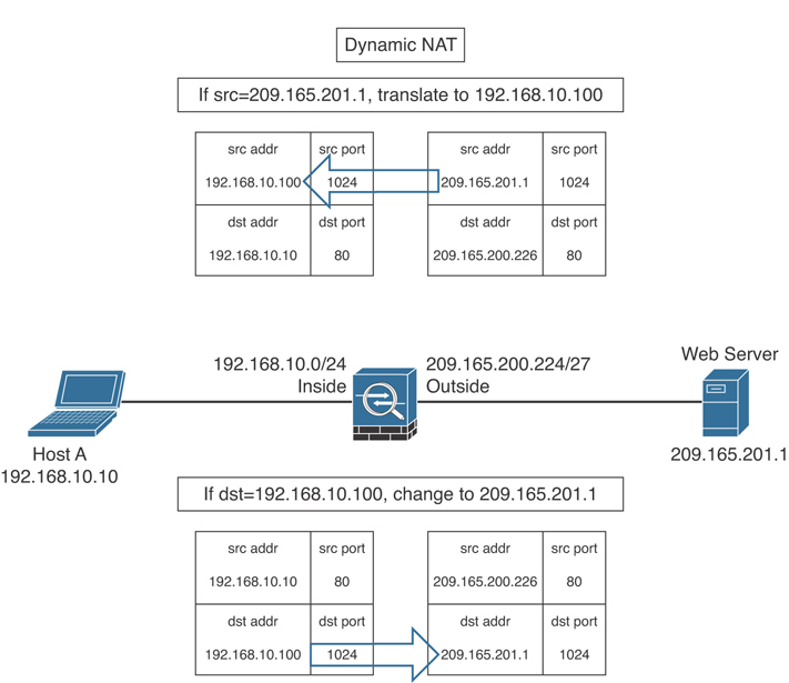
Figure 7-36 Dynamic NAT Example
Port address translation (PAT) defines a many-to-one address mapping when a packet passes through the Cisco ASA and matches criteria for translation. The Cisco ASA creates the translation table by looking at the Layer 4 information in the header to distinguish between the inside hosts using the same global IP address.
Figure 7-37 illustrates an appliance set up for PAT for the inside network of 192.168.10.0/24. However, only one global address is available for translation. If two inside hosts, 192.168.10.10 and 192.168.10.20, require connectivity to an outside host, 209.165.201.1, the Cisco ASA builds the translation table by evaluating the Layer 4 header information. In this case, because both inside hosts have the same source port number, the Cisco ASA assigns a random source port number to keep both entries unique from each other. This way, when the response from the web server returns to the security appliance, the Cisco ASA knows which inside host to forward the packets.

Figure 7-37 PAT Example
The Cisco ASA supports the following four methods to translate an address:
Static NAT/PAT
Dynamic NAT/PAT
Policy NAT/PAT
Identity NAT
Static NAT defines a fixed translation of an inside host or subnet address to a global routable address or subnet. The Cisco ASA uses the one-to-one methodology by assigning one global IP address to one inside IP address. Thus, if 100 hosts residing on the inside network require address translation, the Cisco ASA should be configured for 100 global IP addresses. Additionally, the inside hosts are assigned the same IP address whenever the Cisco ASA translates the packets going through it. This is a recommended solution in scenarios in which an organization provides services such as email, web, DNS, and FTP for outside users. Using static NAT, the servers use the same global IP address for all the inbound and outbound connections.
Static PAT, also known as port redirection, is useful when the Cisco ASA needs to statically map multiple inside servers to one global IP address. Port redirection is applied to traffic when it passes through the Cisco ASA from a lower-security-level interface to a higher-security-level interface. The outside hosts connect to the global IP address on a specific TCP or UDP port, which the Cisco ASA redirects to the appropriate internal server, as shown in Figure 7-38.
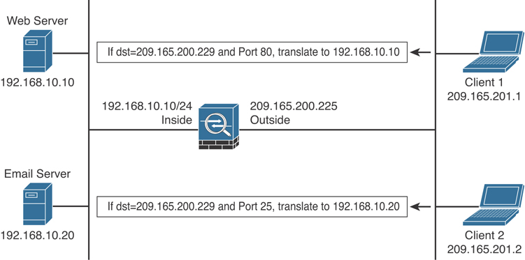
Figure 7-38 Port Redirection Example
The Cisco ASA redirects traffic destined for 209.165.200.229 on TCP port 80 to 192.168.10.10. Similarly, any traffic destined for 209.165.200.229 on TCP port 25 is redirected to 192.168.10.20. The Cisco ASA allows the use of either a dedicated IP address or the global interface’s IP address for port redirection. When port redirection is set up to use the public interface’s IP address, the Cisco ASA uses the same address for the following:
Address translation for the traffic traversing through the security appliance
Traffic destined for the security appliance
Dynamic NAT assigns a random IP address from a preconfigured pool of global IP addresses. The Cisco ASA uses a one-to-one methodology by allocating one global IP address to an inside IP address. Hence, if 100 hosts reside on the inside network, then you have at least 100 addresses in the pool of addresses. This is a recommended solution in scenarios in which an organization uses protocols that don’t contain Layer 4 information, such as Generic Routing Encapsulation (GRE), Reliable Datagram Protocol (RDP), and Data Delivery Protocol (DDP). After the Cisco ASA has built a dynamic NAT entry for an inside host, any outside machine can connect to the assigned translated address, assuming that the Cisco ASA allows the inbound connection.
With dynamic PAT, the Cisco ASA builds the address translation table by looking at the Layer 3 and Layer 4 header information. It is the most commonly deployed scenario because multiple inside machines can get outside connectivity through one global IP address. In dynamic PAT, the Cisco ASA uses the source IP addresses, the source ports, and the IP protocol information (TCP or UDP) to translate an inside host. As with static PAT, you have the option of using either a dedicated public address or the IP address of an interface for translations. As shown in Figure 7-39, two inside machines are accessing an external web server, using the IP address of the outside interface.
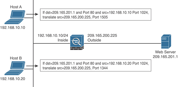
Figure 7-39 Dynamic PAT Example
The Cisco ASA supports up to 65,535 PAT translations using a single address. You can also use extended PAT, which allows you to have 65,535 PAT translations per service as opposed to per address.
Policy NAT/PAT translates the IP address of the packets passing through the Cisco ASA only if those packets match a defined criterion or policy. You define the policy by identifying interesting traffic through the use of ACLs or by using manual NAT by identifying specific traffic. If traffic matches the defined entries in the ACL, then the original source or destination address can be translated to a different address.
In many scenarios, you want to bypass address translation so that the security appliance does not change the source or the destination address. You may want to bypass address translation, also known as identity NAT, if you already have address translation defined for the inside network so that hosts can get Internet connectivity. However, you do not want to change their addresses if they send traffic to a specific host or network.
TCP Intercept is a security feature that protects the TCP-based servers from TCP SYN attacks by filtering the bogus denial-of-service (DoS) traffic. The TCP Intercept feature is configured using the MPF to set connection limits. The security appliance also protects network resources from an unexpected increase in the number of connections by setting maximum limits. This is applicable for both TCP- and UDP-based connections.
Cisco ASA Auto NAT
The Cisco ASA allows you to define your NAT policies within a network object; thus it is also known as Network Object NAT. A network object can be a host, a range of IP addresses, a subnet, or a network. This mode is typically used when you need to translate the source address of a new object or a predefined object in the configuration. NAT configuration is added with the object definition. The key point is that it is mainly used when you need to translate the source address of an object. This is a popular choice of address translation because most policies require translation of the source address.
You can also enable the Cisco ASA to perform NAT automatically with the “Auto NAT” feature. Auto NAT is helpful when you want to translate the source address of an object regardless of the destination address. In this mode, you define an object and add an address translation policy within the object definition.
Implementing Access Control Policies in the Cisco Firepower Threat Defense
As you learned in previous sections in this chapter, access control policy is the crossroads for all traffic in a firewall. The Cisco FTD provides different ways to configure access control policies. Traditionally, policies tend to proliferate and settings diverge. In addition, the defaults for new policies change over time and inconsistencies lead to problems with detection. At the end of the day, complexity is the enemy of security. It is recommended that you take a consistent approach to make things simple and not over-complicate your access control and intrusion policies.
The Cisco FTD combines the features provided by the traditional Cisco ASA firewall and next-generation Firepower services, including different advanced security technologies, such as network discovery, application control, file control, security intelligence, and a Snort-based intrusion prevention system. When you configure the Cisco FTD to block from an ingress to egress interface, the access control is performed by either the Firewall engine or the Firepower engine. Subsequently, if two hosts experience any connectivity issues while sending traffic through a Cisco FTD device, it is essential to analyze packets from both engines to determine the root cause of the problem. For example, to investigate any registration or communications issues between FTD and the FMC, capturing traffic from the Firepower management interfaces is one of the key troubleshooting steps.
Figure 7-40 provides a high-level overview of how traffic flows through a Cisco FTD. When the Firewall engine receives a packet on an ingress interface, it redirects it to the Firepower engine for inspection and policy checks. The Firepower engine will block the traffic if it is not compliant with the configured security policies or it will forward the packet via the egress interface if it complies with the configured policies.
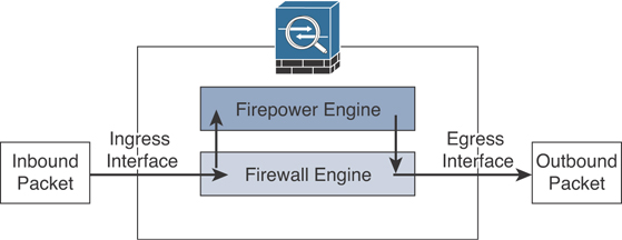
Figure 7-40 Cisco FTD Flow of Traffic High-Level Overview
The Cisco FTD supports a wide range of block actions including the following:
simple blocking
blocking with reset
interactive blocking
interactive blocking with reset
You can choose any interface mode to apply a policy, regardless of the underlying deployment mode (routed or transparent). On the other hand, the capability of an interface mode defines whether the Cisco FTD is able to block any suspicious traffic it detects.
Let’s take a look at how to configure an access control policy to block any Telnet (TCP port 23) traffic traversing the firewall.
To add a new access control policy, navigate to the Policies > Access Control > Access Control page in the Cisco FMC. Click the New Policy button to add the new policy. The screen shown in Figure 7-41 is displayed.
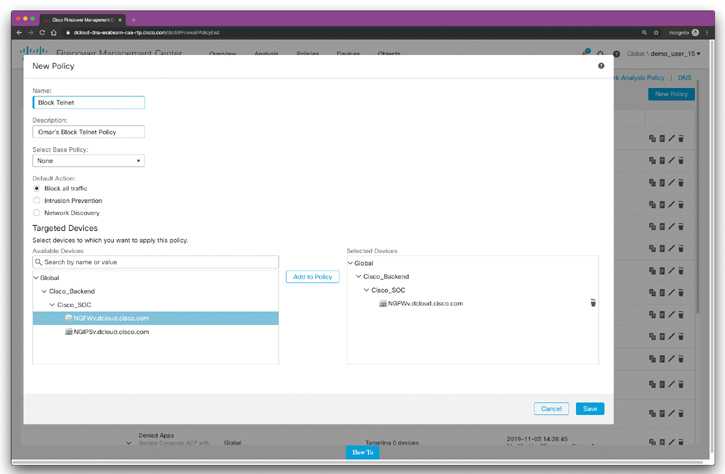
Figure 7-41 Creating an Access Control Policy in Cisco FMC
In Figure 7-41, the policy is named Block Telnet and the default action is to block all traffic. There are two available devices. The policy is applied to a virtual FTD device (vFTD). When you click Save, the new policy is added to the configuration.
The next step is to add an access control rule. To add an access control rule, click Add Rule and the screen in Figure 7-42 will appear.
The access control rule shown in Figure 7-42 is named Block Telnet Rule, and the action is set to Block with reset. The rule is configured to block TCP port 23 (Telnet) traversing all interfaces.
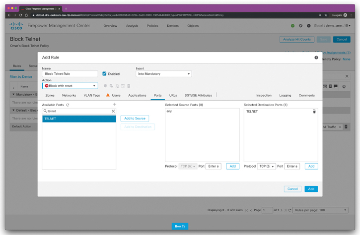
Figure 7-42 Creating an Access Control Rule for the New Policy in Cisco FMC
Cisco Firepower Intrusion Policies
Cisco delivers several intrusion policies with the Firepower System. These policies are designed by the Cisco Talos Security Intelligence and Research Group, which sets the intrusion and preprocessor rule states and advanced settings. You cannot modify these policies. However, you can change the action to take for a given rule, as described in “Changing Intrusion Rule Actions.”
For access control rules that allow traffic, you can select one of the following intrusion policies to inspect traffic for intrusions and exploits. An intrusion policy examines decoded packets for attacks based on patterns and can block or alter malicious traffic.
Network analysis and intrusion policies work together as part of the Cisco FTD intrusion detection and prevention feature. The term intrusion detection generally refers to the process of passively analyzing network traffic for potential intrusions and storing attack data for security analysis. The term intrusion prevention includes the concept of intrusion detection but adds the ability to block or alter malicious traffic as it travels across your network. Figure 7-43 shows the details about network analysis and intrusion policies.

Figure 7-43 Network Analysis and Intrusion Policies
Both network analysis and intrusion policies are invoked by a parent access control policy, but at different times. As the system analyzes traffic, the network analysis (decoding and preprocessing) phase occurs before and separately from the intrusion prevention (additional preprocessing and intrusion rules) phase. Together, network analysis and intrusion policies provide broad and deep packet inspection. They can help you detect, alert on, and protect against network traffic that could threaten the availability, integrity, and confidentiality of hosts and their data. The Cisco FTD has several similarly named network analysis and intrusion policies (for example, Balanced Security and Connectivity) that complement and work with each other. By using system-provided policies, you can take advantage of the experience of the Cisco Talos Security Intelligence and Research Group. For these policies, Talos sets intrusion and preprocessor rule states, as well as provides the initial configurations for preprocessors and other advanced settings.
Figure 7-44 shows an example of an intrusion policy.

Figure 7-44 Intrusion Policy Example
The policy in Figure 7-44 is called omar-intrusion-policy-1, and it is configured to drop noncompliant traffic inline. The policy is configured with a base policy called Balanced Security and Connectivity.
The following are a few facts about intrusion policies:
In an inline deployment (that is, where relevant configurations are deployed to devices using routed, switched, or transparent interfaces, or inline interface pairs), the system can block traffic without further inspection at almost any step in the illustrated process. Security Intelligence, the SSL policy, network analysis policies, file policies, and intrusion policies can all either drop or modify traffic. Only the network discovery policy, which passively inspects packets, cannot affect the flow of traffic.
Common issues in intrusion policies include when you deploy a flat policy structure, inconsistent rule sets, and when you configure difficult rules for a new administrator to understand.
Every user-created policy depends on another policy as its “Base.”
All policies trace their roots back to a “Talos-provided-base” policy. These base policies are as follows:
Connectivity Over Security: This policy is built for organizations where connectivity (being able to get to all resources) takes precedence over network infrastructure security. The intrusion policy enables far fewer rules than those enabled in the Security Over Connectivity policy. Only the most critical rules that block traffic are enabled. Select this policy if you want to apply some intrusion protection but you are fairly confident in the security of your network.
Balanced Security and Connectivity: This policy is designed to balance overall network performance with network infrastructure security. This policy is appropriate for most networks. Select this policy for most situations where you want to apply intrusion prevention.
Security over Connectivity: This policy is built for organizations where network infrastructure security takes precedence over user convenience. The intrusion policy enables numerous network anomaly intrusion rules that could alert on or drop legitimate traffic. Select this policy when security is paramount or for traffic that is high risk.
No Rules Active: No rules are active at this point.
Maximum Detection: This policy is built for organizations where network infrastructure security is given even more emphasis than is given by the Security Over Connectivity policy, with the potential for even greater operational impact. For example, the intrusion policy enables rules in a large number of threat categories, including malware, exploit kit, old and common vulnerabilities, and known in-the-wild exploits. If you select this policy, carefully evaluate whether too much legitimate traffic is being dropped.
When the system identifies a possible intrusion, it generates an intrusion or preprocessor event (sometimes collectively called intrusion events). Managed devices transmit their events to the Firepower Management Center, where you can view the aggregated data and gain a greater understanding of the attacks against your network assets. In an inline deployment, managed devices can also drop or replace packets that you know to be harmful. Each intrusion event in the database includes an event header and contains information about the event name and classification; the source and destination IP addresses; ports; the process that generated the event; and the date and time of the event, as well as contextual information about the source of the attack and its target. For packet-based events, the system also logs a copy of the decoded packet header and payload for the packet or packets that triggered the event.
The preceding sections explain how to configure various aspects of an IPS policy. After all the changes have been made, the policy doesn’t take effect unless it is committed. When you click the Commit Changes button (refer to Figure 7-44), you might be prompted to insert a comment that describes the change. The comment is a configurable option under the intrusion policy preferences. Comments are stored in the audit logs and thus are searchable. Alternatively, you can choose to discard the changes, in which case you remove the changes since the last commit. Finally, if you choose to leave the Intrusion Policy screen with uncommitted changes, the changes are not lost. They remain uncommitted and can be revisited later to be committed or discarded.
After a policy is committed, Firepower performs a validation check to make sure there are no incorrect or invalid settings. For example, enabling a rule that uses a disabled preprocessor would be flagged after the commit.
Variables
Variables are used in multiple locations in Cisco Firepower NGIPS. IPS rules use preconfigured variables representing networks and ports. For example, the inside (protected) network is represented by the variable $HOME_NET, and the outside (unprotected) network is represented by the variable $EXTERNAL_NET. Other variables are used in more specialized rules. For example, $HTTP_SERVERS represents the web servers and $HTTP_PORTS the ports used by these servers.
There are two types of variables:
System default variables that are the preconfigured variables in the system: These include $AIM_SERVERS, $DNS_SERVERS, $EXTERNAL_NET, $FILE_DATA_PORTS, $GTP_PORTS, $HOME_NET, $HTTP_PORTS, $HTTP_SERVERS, $ORACLE_PORTS, $SHELLCODE_PORTS, and more.
Policy variables that override default variable: They are used in specific policies.
When creating a network variable, you can use more than one address; just separate addresses with commas—for example, [192.168.1.2, 10.10.10.2, 172.18.1.2]. You can also use CIDR representation—for example, [192.168.1.2, 10.10.10.2, 172.18.1.0/24]. In addition, you can exclude addresses from a list by using an exclamation point—for example, [192.168.1.2, !10.10.10.2, 172.18.1.0/24].
When creating port variables, you can use ranges, such as [25-121]. The following are some other possibilities:
For ports less than a number, you can use the format [-1024].
For ports more than a number, you can use the format [1024-].
To exclude ports, you can use the format [!25].
To list ports, you can use the format [25, !21, 80-].
When you accurately define variables, the processing of the rules using them is optimized and the right systems are monitored for illegitimate traffic. By leveraging variables, you can more efficiently change the variable value without changing all the rules for which that variable is used. For example, if multiple rules are defined to protect the web servers, you would need only to define or update the variable $HTTP_SERVERS instead of updating all the rules.
Platform Settings Policy
Cisco Firepower deployments can take advantage of platform settings policies. These policies are a shared set of parameters that define the aspects of a Cisco Firepower device that are likely to be similar to other managed devices. Examples of these platform settings policies are time and date settings, external authentication, and other common administrative features.
Shared platform policies allow you to configure multiple managed devices at once. This, in turn, allows you to be more consistent and to streamline your management efforts.
When you perform any changes to a platform settings policy, it takes effect in all the managed devices where the policy is applied.
Cisco NGIPS Preprocessors
IPS pattern matching is almost impossible because of the different protocols and their intricacies. For example, matching a file pattern in SMTP email traffic is not performed the same way as matching it when flowing through HTTP with compression enabled. For that reason, the Cisco NGIPS offers a variety of preprocessors that normalize traffic so that it can be matched against the defined Snort rules.
The preprocessors attempt to make the streams of packets as much as possible like the reassembled packets that will be seen by the endpoints receiving them. For example, the preprocessors perform checksum calculation, stream and fragment reassembly, stateful inspection, and more. Each preprocessor has a variety of settings to be configured in order to minimize false positives and false negatives. In addition, customized ones perform dedicated resources to detect specific suspicious attack activity to avoid burdening the system with these tasks.
The following preprocessors are available in the Cisco Firepower NGIPS:
DCE/RPC: The DCE/RPC preprocessor monitors DCE/RPC and SMB protocol streams and messages for anomalous behavior or evasions.
DNS: The DNS preprocessor inspects DNS responses for overflow attempts and for obsolete and experimental DNS record types.
FTP and Telnet: The FTP and Telnet preprocessor normalizes FTP and Telnet streams before they are passed to the IPS engine. It requires TCP stream preprocessing.
HTTP: The HTTP preprocessor normalizes HTTP requests and responses for IPS processing, separates HTTP messages to improve IPS rule performance, and detects URI-encoding attacks.
Sun RPC: The Sun RPC preprocessor normalizes and reassembles fragmented SunRPC records so the rules engine can process the complete record.
SIP: The SIP preprocessor normalizes and inspects SIP messages to extract the SIP header and body for further rule processing and generates events when identifying out-of-order calls and SIP message anomalies.
GTP: The GTP preprocessor normalizes General Packet Radio Service (GPRS) Tunneling Protocol (GTP) command channel signaling messages and sends them to the rules engine for inspection.
IMAP and POP: The IMAP and POP preprocessors monitor server-to-client email traffic and alert on anomalies. They also extract and decode email attachments and allow further processing by the NGIPS rules engine and other Cisco Firepower features.
SMTP: The SMTP preprocessor inspects SMTP traffic for anomalous behavior and extracts and decodes email attachments for further processing.
SSH: The SSH preprocessor detects SSH buffer overflow attempts and monitors for illegal SSH versions.
SSL: The SSL preprocessor monitors the SSL handshake transactions. After the SSL session is encrypted, the SSL preprocessor stops inspecting. It requires TCP stream preprocessing. The SSL preprocessor can reduce the amount of false positives and save detection resources from the IPS system.
SCADA: There are two supervisory control and data acquisition (SCADA) protocols for which the Cisco Firepower NGIPS offers preprocessors: DNP3 and Modbus. These protocols monitor and control industrial facilities. The SCADA preprocessors monitor the DNP and Modbus protocols for anomalies and decode their messages for further rule inspection.
Network: Multiple network and transport layer preprocessors detect attacks exploiting the following:
Checksum verification
Ignoring VLAN headers
Inline normalization
IP defragmentation
Packet decoding
TCP stream
UDP stream
The packet decoder normalizes packet headers and payloads for further processing. The inline normalization preprocessor normalizes traffic to prevent evasion techniques in inline deployments. The rest of the network preprocessors detect anomalous network or transport layer behavior.
Threat detection: The threat detection preprocessors detect specific threats (such as port scan detection, rate-based attack prevention, and sensitive data detection).
Cisco Advanced Malware Protection (AMP)
The Cisco Advanced Malware Protection (AMP) solution enables you to detect and block malware, continuously analyze for malware, and get retrospective alerts. Traditionally, Cisco has the concept of AMP for Networks and AMP for Endpoints.
Cisco AMP for Networks provides next-generation security services that go beyond point-in-time detection. It provides continuous analysis and tracking of files and also retrospective security alerts so that a security administrator can take action during and after an attack. The file trajectory feature of Cisco AMP for Networks tracks file transmissions across the network, and the file capture feature enables a security administrator to store and retrieve files for further analysis.
Cisco acquired a security company called ThreatGRID that provides cloud-based and on-premises malware analysis solutions. Cisco integrated Cisco AMP and Threat Grid to provide a solution for advanced malware analysis with deep threat analytics. The Cisco AMP Threat Grid integrated solution analyzes millions of files and correlates them with hundreds of millions of malware samples. This provides a look into attack campaigns and how malware is distributed. This solution provides a security administrator with detailed reports of indicators of compromise and threat scores that help prioritize mitigations and recover from attacks.
Cisco AMP has the following features:
File reputation: AMP allows you to analyze files inline and block or apply policies.
File sandboxing: AMP allows you to analyze unknown files to understand true file behavior.
File retrospection: AMP allows you to continue to analyze files for changing threat levels.
There are major architectural benefits to the AMP solution, which leverages a cloud infrastructure for the heavy lifting. The architecture of AMP can be broken down into three main components: the AMP cloud, AMP client connectors, and intelligence sources. AMP client connectors include AMP for Networks, AMP for Endpoints, and AMP for Content Security.
The AMP cloud contains many different analysis tools and technologies to detect malware in files, including the Threat Grid analysis solution. Cisco’s research teams, including the Cisco Talos Security Intelligence and Research Group, feed information about malware into the AMP cloud. Threat intelligence from Cisco products, services, and third-party relationships is also sent to the AMP cloud. The following are some examples of threat intelligence sources:
Snort, ClamAV, and Immunet AV open source communities: Users of these open source projects contribute threat information daily.
Talos: The Cisco Talos Security Intelligence and Research Group is a team of leading threat researchers that contributes to the threat information ecosystem of Cisco security products. Talos team members get threat information from a variety of sources and their own internal research efforts. Talos maintains the official rule sets of Snort.org, ClamAV, SenderBase.org, and SpamCop. Talos is also the primary team that contributes to the Cisco Collective Security Intelligence (CSI) ecosystem. A variety of sources contribute to the vast amount of data provided to Cisco through submitted malware samples, data from the web, and email traffic monitored by Cisco products and other third-party sources.
Threat Grid: This deep threat analysis solution leverages many identification techniques, including sandboxing. Threat Grid is built as a cloud architecture and is used to do deep analysis of file samples submitted to the AMP Threat Grid cloud. The analysis results are fed into the AMP cloud and can be used to update file disposition (the result).
The most critical item of the Cisco AMP architecture is the AMP cloud itself. The AMP cloud has two deployment methods—public and private—and regardless of the deployment chosen, the role of the cloud is the same.
The AMP cloud houses all the detection signatures. A major benefit of storing these signatures in the cloud is that it reduces the client connector size and reduces the processing requirements on the client, since the bulk of the work is handled in the cloud.
An interesting and fairly unique feature is that AMP administrators can create custom signatures in the cloud, and then those custom signatures are pushed to the connectors. In addition, the cross-referencing of files and signatures is done in the AMP cloud, so the cloud can be self-updating, without having to constantly communicate updates to the connectors.
The AMP cloud is also responsible for large-scale data processing, or big data. The data comes to the AMP cloud from multiple sources, including honeypots, threat feeds, open source communities, AV solutions such as Immunet AV and ClamAV, and more. File samples are provided to the AMP cloud, where they are processed. If the disposition of a sample file is deemed to be malicious, it is stored in the cloud and reported to the client connectors that see the same file.
Advanced analytic engines, including Threat Grid, are part of the AMP cloud and are constantly correlating the incoming data. The analytical results are used to update the AMP signatures. In addition to the advanced analytics, machine-learning engines are employed to further refine signatures and reevaluate detections that have already been performed. The cloud is not just a repository of signatures; the decision making is performed in real time, evolving constantly based on the data received.
Prevention involves keeping malware at bay. With prevention, speed is critical. It requires real-time, dynamic decisions to be made from real-world data. The data must have high accuracy, with low false positives and false negatives. Prevention could also be viewed as the “security control mode.”
As illustrated in Figure 7-45, the AMP cloud’s prevention framework is made up of seven core components: 1-to-1 signatures, Ethos, Spero, indicators of compromise (IOCs), device flow correlation, advanced analytics, and dynamic analysis.
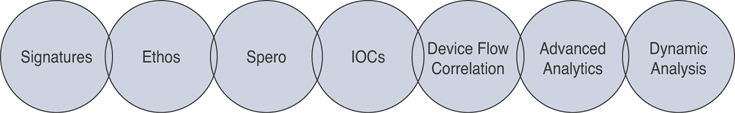
Figure 7-45 The AMP Cloud’s Protection Framework
1-to-1 signatures are a traditional technology that is used all over the security industry in various forms. With these signatures, a hash is created of a file, and that hash is compared to a database. If a match is found, the specific file is known, and a verdict—clean or malicious—is returned. If the hash has not been seen before, the cloud returns a verdict of unknown. The benefit of this method is that it can quickly identify and block malicious files. The downside is that a simple change to a file also changes the hash, thereby evading the signature.
AMP differentiates itself from other 1-to-1 signature solutions by storing the signature database in the cloud instead of on the client. The database is quite large, and many solutions cut corners by including only a subset of the signatures in the full database. Storing the database in the cloud allows AMP to leverage the entire database. Comparing the files to the database can be quite resource intensive. AMP does the comparison in the cloud, freeing those resources from the client connector. AMP is also able to collect, process, and detect in near real time.
The next component of the protection framework is the Ethos engine. Ethos is a “fuzzy fingerprinting” engine that uses static or passive heuristics. The engine creates generic file signatures that can match polymorphic variants of a threat. This is useful because when a threat morphs or a file is changed, the structural properties of that file often remain the same, even though the content has changed.
Unlike most other signature tools, Ethos uses distributed data mining to identify suitable files. It uses in-field data for sources, which provide a highly relevant collection from which to generate the signatures. Ethos is completely automated and provides rapid generation of the generic signatures that are based on in-field data instead of relying on individual “rock star” engineers to generate a limited number of generic signatures.
Spero is a machine-learning-based technology that proactively identifies threats that were previously unknown. It uses active heuristics to gather execution attributes, and because the underlying algorithms come up with generic models, it can identify malicious software based on its general appearance rather than based on specific patterns or signatures.
An indicator of compromise (IOC) is any observed artifact on a system or a network that could indicate an intrusion. There may be artifacts left on a system after an intrusion or a breach, and they can be expressed in a language that describes the threat information, known as an IOC. The sets of information describe how and where to detect the signs of the intrusion or breach. IOCs can be host-based and/or network-based artifacts, but the scan actions are carried out on the host only.
IOCs are very high-confidence indicators, and they may describe numerous specific items, including FileItem, RegistryItem, EventLogItem, ProcessItem, and ServiceItem.
Device flow correlation provides a kernel-level view into network I/O. It allows for blocking or alerting on network activity, traced back to the initiating process itself. It enables internal and external networks to be monitored, leverages IP reputation data, and offers URL/domain logging. The flow points are extra telemetry data and are not file disposition specific.
Cisco provides intelligence on many malicious destinations, including generic command-and-control (CnC or C2) servers, phishing hosts, zero-access C2 servers, and more.
Advanced analytics consists of a set of multifaceted engines that provide big data context beyond a single host and beyond a single file. Advanced analytics highlights files executed in an environment, from least common to most. This can aid in identifying previously undetected threats that may have only been seen by a small number of users.
Dynamic analysis performed by Cisco AMP Threat Grid integration is not a single tool. It is a full solution for dynamic malware analysis and threat intelligence. It performs high-speed, automated analysis with adjustable runtimes while not exposing any tags or other indicators that malware could use to detect that it is being observed.
Threat Grid provides video playbacks, a glovebox for malware interaction and operational troubleshooting, a process graph for visual representation of process lineage, and a threat score with behavior indicators.
It searches and correlates all data elements of a single sample against billions of sample artifacts collected and analyzed over years, leveraging global and historic context. This enables an analyst to better understand the relevancy of a questionable sample as it pertains to the analyst’s own environment.
Threat Grid was architected from the ground up as a cloud solution with an API designed to integrate with existing IT security solutions and to create custom threat intelligence feeds. It can automatically receive submissions from other solutions and pull the results into your environment.
Many think that Threat Grid is a sandboxing solution. It is much more than just that, however; sandboxing is a piece of the solution, and Threat Grid’s sandboxing functions are performed in a way that evades detection by malware. Threat Grid uses an outside-in approach, with no presence in the virtual machine. The sandboxing’s dynamic analysis includes an external kernel monitor, dynamic disk analysis that illuminates any modifications to the physical disk (such as the master boot record), monitoring user interaction, video capture and playback, process information, artifacts, and network traffic.
Threat Grid supports the following samples and object types:
Executable files (.EXE) and libraries (.DLL)
Java archives (.JAR)
Portable document format (.PDF)
Office documents (.RTF, .DOC, .DOCX, .XLS, .XLSX, .PPT, .PPTX)
ZIP containers (.ZIP)
Quarantine containers
URLs
HTML documents
Flash
Retrospection means taking a look at what has already transpired; it involves tracking system behavior regardless of disposition, focusing on uncovering malicious activity. Retrospection could be viewed as the “incident response mode,” using continuous analysis to reactively act on a file that was assigned a clean disposition once but was later found to have a bad disposition.
The retrospective framework is designed to show the trajectory of a malicious file, with a goal of 30 days of telemetry data. Even files that are originally given a clean verdict are tracked, and if a clean file is later found to be malicious, all connectors that have seen the file are notified to quarantine the file retrospectively.
Figure 7-46 shows the network file trajectory for a confirmed piece of malware in the Cisco FMC.
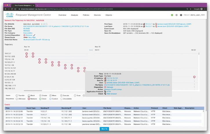
Figure 7-46 The Network File Trajectory for a Confirmed Piece of Malware in the Cisco FMC
Security Intelligence, Security Updates, and Keeping Firepower Software Up to Date
You learned that Security Intelligence uses reputation intelligence to quickly block connections to or from IP addresses, URLs, and domain names. This is called Security Intelligence blacklisting. Security Intelligence is an early phase of access control, before the system performs more resource-intensive evaluation. Blacklisting improves performance by quickly excluding traffic that does not require inspection. Although you can configure custom blacklists, Cisco provides access to regularly updated intelligence feeds. Sites representing security threats such as malware, spam, botnets, and phishing appear and disappear faster than you can update and deploy custom configurations.
Security Intelligence Updates
The following are some best practices around security intelligence updates:
The default update frequency is 2 hours. In some scenarios, you may want to reduce this for more agile blacklisting.
The minimum intervals should be as follows:
Talos network feed: 5 minutes
Talos URL/DNS feed: 30 minutes
Custom feed: 30 minutes
Use custom feeds. Everybody has a custom blacklist, and feeds are the best way to implement these in Cisco FTD and Firepower devices. Security Intelligence lists and feeds are not the same. Security intelligence lists are okay, but remember you need to deploy policy to update them.
Keeping Software Up to Date
Keeping software up to date is not exciting but it is important. The following are the different software update types in Cisco FTD and Firepower devices:
Snort rules updates (SRUs): Contain the latest Snort rules. SRUs are released on Tuesday and Thursday; however, they can also be released out-of-band for critical updates. Each SRU contains a complete rule set.
Vulnerability database (VDB) updates: Updates for known vulnerabilities, identified with a Common Vulnerability and Exposures (CVE) identifier. These vulnerability reports are used to set impact on intrusion events.
Geolocation updates: These are updated weekly.
Firepower software patches and updates.
Exam Preparation Tasks
As mentioned in the section “How to Use This Book” in the Introduction, you have a couple of choices for exam preparation: the exercises here, Chapter 12, “Final Preparation,” and the exam simulation questions in the Pearson Test Prep Software Online.
Review All Key Topics
Review the most important topics in this chapter, noted with the Key Topic icon in the outer margin of the page. Table 7-3 lists these key topics and the page numbers on which each is found.
Table 7-3 Key Topics for Chapter 7
Key Topic Element |
Description |
Page Number |
Section |
Cisco Firepower Threat Defense (FTD) |
|
List |
An introduction to Cisco’s Next-Generation Intrusion Prevention System (NGIPS) |
|
List |
List of the supplemental capabilities introduced by Cisco NGIPS |
|
List |
List of the most important capabilities of Cisco NGIPS |
|
Section |
Surveying the Cisco Firepower Management Center (FMC) |
|
Section |
Exploring the Cisco Firepower Device Manager (FDM) |
|
Section |
Cisco Defense Orchestrator |
|
Section |
Comparing Network Security Solutions That Provide Firewall Capabilities |
|
Section |
Deployment Modes of Network Security Solutions and Architectures That Provide Firewall Capabilities |
|
Section |
Routed vs. Transparent Firewalls |
|
Section |
Security Contexts |
|
Section |
Single-Mode Transparent Firewalls |
|
Section |
Surveying the Cisco FTD Deployment Modes |
|
Section |
Cisco FTD Interface Modes |
|
Section |
Inline Pair |
|
Section |
Inline Pair with Tap |
|
Section |
Passive Mode |
|
Section |
Passive with ERSPAN Mode |
|
Section |
Additional Cisco FTD Deployment Design Considerations |
|
Section |
High Availability and Clustering |
|
Section |
Implementing Access Control Lists in Cisco ASA |
|
List |
Defining the five-tuple |
|
List |
Types of ACL supported in the Cisco ASA |
|
Paragraph |
Exploring the different security levels of Cisco ASA interfaces |
|
Section |
Cisco ASA Application Inspection |
|
Section |
To-the-Box Traffic Filtering in the Cisco ASA |
|
Section |
Standard ACLs |
|
Section |
ICMP Filtering in the Cisco ASA |
|
Section |
Network Address Translation in Cisco ASA |
|
List |
Understanding the different methods to translate an address in the Cisco ASA |
|
Section |
Cisco ASA Auto NAT |
|
Section |
Implementing Access Control Policies in the Cisco Firepower Threat Defense |
|
Section |
Cisco Firepower Intrusion Policies |
|
Section |
Variables |
|
Section |
Platform Settings Policy |
|
Section |
Cisco NGIPS Preprocessors |
|
Section |
Cisco Advanced Malware Protection (AMP) |
|
Tip |
Exploring standards for threat intelligence exchange, including STIX and TAXII |
|
Paragraph |
Understanding retrospection and retrospective analysis |
Define Key Terms
Define the following key terms from this chapter and check your answers in the glossary:
Review Questions
1. When you add a Cisco FTD or Firepower device to FMC, what information is required?
Serial number
The initial access intrusion policies configured in the FTD or Firepower device
The initial access control policies configured in the FTD or Firepower device
A registration key
2. Which of the following is a best practice for security intelligence updates?
The default security intelligence update frequency is 2 hours. In some scenarios, you may want to increase this update frequency to avoid network bandwidth consumption.
The default security intelligence update frequency is 2 hours. In some scenarios, you may want to reduce this for more agile blacklisting.
Configure Snort Rule Updates to be done twice a week.
Configure vulnerability database updates every second Tuesday of the month (Microsoft Patch Tuesday).
3. Variables are used in multiple locations in Cisco Firepower NGIPS. IPS rules use preconfigured variables representing networks and ports. Which of the following are system default variables that are preconfigured in Cisco Firepower devices?
$FILE_DATA_PORTS
$HOME_NET
$HTTP_SERVERS
All of these answers are correct.
4. IPS pattern matching is almost impossible because of the different protocols and their intricacies. For example, matching a file pattern in SMTP email traffic is not performed the same way as matching it when flowing through HTTP with compression enabled. For that reason, the Cisco NGIPS offers a variety of ___________ that normalize traffic so that it can be matched against the defined Snort rules.
preprocessors
intrusion policies
variables
access control rules
5. You are tasked to deploy an intrusion policy designed to balance overall network performance with network infrastructure security. Which of the following base policies would you deploy in situations where you want to apply intrusion prevention?
Connectivity Over Security
Balanced Security and Connectivity
Balanced Security and Connectivity over Security
Maximum Detection
6. You are tasked to configure NAT and translate the source address of an object regardless of the destination address. Which of the following NAT configuration features would you deploy to accomplish this task?
Auto NAT
Destination NAT
Identity NAT
Port redirection
7. Which of the following statements is not true about standard ACLs?
Standard ACLs are used when the source network in the traffic is not important.
Standard ACLs are used by processes, such as OSPF and VPN tunnels, to identify traffic based on the destination IP addresses.
Standard ACLs can be used with route maps.
Standard ACLs provide a way to group similar items together to reduce the number of ACEs.
8. Cisco ASA provides the Modular Policy Framework (MPF) to provide application security or perform Quality of Service (QoS) functions. The MPF offers a consistent and flexible way to configure the Cisco ASA application inspection and other features in a manner similar to that used for the Cisco IOS Software Modular QoS CLI. Which of the following are commands associated with the MPF?
class-map
policy-map
service-policy
All of these answers are correct.
9. Which of the following is not a step in the Cisco FTD cluster unit transition?
After the unit boots, it looks for a master over the cluster control link.
If there are no master units, it waits 45 seconds before assuming the master role. If a master already exists, it becomes a slave and the configuration is synchronized.
If there is a synchronization or health issue, the unit is considered disabled in the cluster.
After the master boots, it creates a logical interface and assigns an IP address to that interface to communicate to the other units in the cluster.
10. Which of the following can be deployed to generate, transport, and consume threat intelligence information?
A TAXII server
A STIX server
A C2 or CnC
A Cybox server