
Chapter 6
Infrastructure Security
This chapter covers the following topics:
Common Layer 2 Threats and How to Mitigate Them
Understanding and Securing the Management Plane
Understanding the Control Plane
Understanding and Securing the Data Plane
Securing the Network Infrastructure Device Image and Configuration Files
Securing the Data Plane in IPv6
Securing Routing Protocols and the Control Plane
In this chapter, you will learn how to secure Layer 2 technologies as well as what are the common Layer 2 threats and how to mitigate them. You will learn what is Network Foundation Protection. This chapter helps you gain an understanding of the management, control, and data planes and how to secure them. You will learn how to implement logging features and how to configure infrastructure devices to synchronize the time with Network Time Protocol (NTP) servers. You will also learn how to secure the network infrastructure device image and configuration files, secure the data plane in IPv6, and how to secure routing protocol implementations.
The following SCOR 350-701 exam objectives are covered in this chapter:
Domain 2: Network Security
2.4 Configure and verify network infrastructure security methods (router, switch, wireless)
2.4.a Layer 2 methods (network segmentation using VLANs and VRF-lite; Layer 2 and port security; DHCP snooping; Dynamic ARP inspection; storm control; PVLANs to segregate network traffic; and defenses against MAC, ARP, VLAN hopping, STP, and DHCP rogue attacks
2.4.b Device hardening of network infrastructure security devices (control plane, data plane, management plane, and routing protocol security)
2.8 Configure secure network management of perimeter security and infrastructure devices (secure device management, SNMPv3, views, groups, users, authentication, and encryption, secure logging, and NTP with authentication)
“Do I Know This Already?” Quiz
The “Do I Know This Already?” quiz allows you to assess whether you should read this entire chapter thoroughly or jump to the “Exam Preparation Tasks” section. If you are in doubt about your answers to these questions or your own assessment of your knowledge of the topics, read the entire chapter. Table 6-1 lists the major headings in this chapter and their corresponding “Do I Know This Already?” quiz questions. You can find the answers in Appendix A, “Answers to the ‘Do I Know This Already?’ Quizzes and Q&A Sections.”
Table 6-1 “Do I Know This Already?” Section-to-Question Mapping
Foundation Topics Section |
Questions |
Securing Layer 2 Technologies |
1 |
Common Layer 2 Threats and How to Mitigate Them |
2 |
Network Foundation Protection |
3 |
Understanding and Securing the Management Plane |
4 |
Understanding the Control Plane |
5 |
Understanding and Securing the Data Plane |
6 |
Securing Management Traffic |
7 |
Implementing Logging Features |
8 |
Configuring NTP |
9 |
Securing the Network Infrastructure Device Image and Configuration Files |
10 |
Securing the Data Plane in IPv6 |
11 |
Securing Routing Protocols and the Control Plane |
12 |
1. Which of the following are different STP port states?
Root port
Designated
Nondesignated
All of these answers are correct.
2. Which of the following are Layer 2 best practices?
Avoid using VLAN 1 anywhere, because it is a default.
Administratively configure access ports as access ports so that users cannot negotiate a trunk and disable the negotiation of trunking (no Dynamic Trunking Protocol [DTP]).
Turn off Cisco Discovery Protocol (CDP) on ports facing untrusted or unknown networks that do not require CDP for anything positive. (CDP operates at Layer 2 and may provide attackers information we would rather not disclose.)
On a new switch, shut down all ports and assign them to a VLAN that is not used for anything else other than a parking lot. Then bring up the ports and assign correct VLANs as the ports are allocated and needed.
All of these answers are correct.
3. The Network Foundation Protection (NFP) framework is broken down into which of the following three basic planes (also called sections/areas)?
Controller plane, administrative plane, management plane
Management plane, control plane, administrative plane
Management plane, control plane, data plane
None of these answers is correct.
4. Which of the following are best practices for securing the management plane?
Enforce password policy, including features such as maximum number of login attempts and minimum password length.
Implement role-based access control (RBAC).
Use AAA services, and centrally manage those services on an authentication server (such as Cisco ISE).
Keep accurate time across all network devices using secure Network Time Protocol (NTP).
All of these answers are correct.
5. Which of the following statements is not true?
Control Plane Protection, or CPPr, allows for a more detailed classification of traffic (more than CoPP) that is going to use the CPU for handling.
The benefit of CPPr is that you can rate-limit and filter this type of traffic with a more fine-toothed comb than CoPP.
Using CoPP or CPPr, you can specify which types of management traffic are acceptable at which levels. For example, you could decide and configure the router to believe that SSH is acceptable at 100 packets per second, syslog is acceptable at 200 packets per second, and so on.
Routing protocol authentication is not a best practice for securing the control plane; it is a best practice to protect the management plane.
6. You were hired to help increase the security of a new company that just deployed network devices in two locations. You are tasked to deploy best practices to protect the data plane. Which of the following techniques and features should you consider deploying to protect the data plane? (Select all that apply.)
Use TCP Intercept and firewall services to reduce the risk of SYN-flood attacks.
Filter (deny) packets trying to enter your network (from the outside) that claim to have a source IP address that is from your internal network.
Deploy CoPP and CPPr in firewalls and IPS systems, as well as routing protocol authentication.
Configure NetFlow and NETCONF for Control Plane Protection.
7. Which of the following are best practices to protect the management plane and management traffic?
Deploy Login Password Retry Lockout to lock out a local AAA user account after a configured number of unsuccessful attempts by the user to log in using the username that corresponds to the AAA user account.
Enable role-based access control (RBAC).
Use NTP to synchronize the clocks on network devices so that any logging that includes timestamps may be easily correlated. Preferably, use NTP Version 3 to leverage its ability to provide authentication for time updates.
All of these answers are correct.
8. Which of the following commands enable timestamps in syslog messages?
service syslog timestamps log datetime
logging timestamps log datetime
service timestamps log datetime
None of these answers is correct.
9. You were hired to configure all networking devices (routers, switches, firewalls, and so on) to generate syslog messages to a security information and event management (SIEM) system. Which of the following is recommended that you do on each of the infrastructure devices to make sure that the SIEM is able to correctly correlate all syslog messages ?
Enable OSPF.
Configure the network infrastructure devices to send syslog messages in batches (at a scheduled interval).
Configure the SIEM to process the syslog messages at a scheduled interval.
Enable NTP.
10. Which of the following is a feature that’s intended to improve recovery time by making a secure working copy of a router or switch image and the startup configuration files (which are referred to as the primary bootset) so that they cannot be deleted by a remote user?
Cisco Resilient Configuration
Cisco Secure Firmware Configuration
Address Space Layout Randomization (ASLR)
None of these answers is correct.
11. If an attacker attempts to spoof many IPv6 destinations in a short time, the router can get overwhelmed while trying to store temporary cache entries for each destination. The ______________feature blocks data traffic from an unknown source and filters IPv6 traffic based on the destination address. It populates all active destinations into the IPv6 first-hop security binding table, and it blocks data traffic when the destination is not identified.
IPv6 Destination Guard
IPv6 Neighbor Cache Guard
IPv6 Hop-by-hop Extension Header
IPv6 Neighbor Cache Resource Starvation
12. BGP keychains enable keychain authentication between two BGP peers. The BGP endpoints must both comply with a keychain on one router and a password on the other router. Which of the following statements is not true regarding BGP keychains?
BGP is able to use the keychain feature to implement hitless key rollover for authentication.
Key rollover specification is time based, and in the event of clock skew between the peers, the rollover process is impacted.
The configurable tolerance specification allows for the accept window to be extended (before and after) by that margin. This accept window facilitates a hitless key rollover for applications (for example, routing and management protocols).
Routing protocols all support a different set of cryptographic algorithms. BGP supports only HMAC-SHA1-12.
Foundation Topics
Securing Layer 2 Technologies
We often take for granted Layer 2 in the network because it just works. Address Resolution Protocol (ARP) and Layer 2 forwarding on Ethernet are both proven technologies that work very well. The CCNP Security and CCIE Security certifications are built with the presumption that candidates understand some of the fundamentals of routing and switching. With this knowledge, your understanding of the details about VLANs, trunking, and inter-VLAN routing is presumed. However, so that you absolutely understand these fundamental concepts, this section begins with a review.
It is important to make sure that the basics are in place so that you can fully understand the discussion about protecting Layer 2 in the last section of this chapter, which covers the really important “stuff.” That section focuses on just a few Layer 2–related security vulnerabilities and explains exactly how to mitigate threats at Layer 2. If you are currently comfortable with VLANs, trunking, and routing between VLANs, you might want to jump right to the last section.
VLAN and Trunking Fundamentals
In Chapter 5, “Network Visibility and Segmentation,” you already learned that VLANs can be used to segment your network and are assigned to switch ports as well as wireless clients to enforce policy. In this chapter, you will also learn about several security challenges when protecting Layer 2 networks, VLAN assignment, and trunking protocols. However, you must understand the basics of how VLANs and trunking operate before you can learn to secure those features. This section reviews how VLANs and trunking are configured and how they operate.
Figure 6-1 serves as a reference for the discussion going forward. You might want to bookmark this page or take a moment to make a simple drawing of the topology. You will want to refer to this illustration often during the discussion.
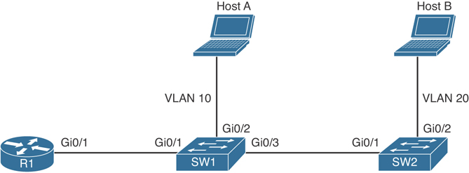
Figure 6-1 VLAN Example
What Is a VLAN?
One way to identify a local area network is to say that all the devices in the same LAN have a common Layer 3 IP network address and that they also are all located in the same Layer 2 broadcast domain. A virtual LAN (VLAN) is another name for a Layer 2 broadcast domain. VLANs are controlled by the switch. The switch also controls which ports are associated with which VLANs. In Figure 6-1, if the switches are in their default configuration, all ports by default are assigned to VLAN 1, and that means all the devices, including the two users and the router, are all in the same broadcast domain, or VLAN.
As you start adding hundreds of users, you might want to separate groups of users into individual subnets and associated individual VLANs. To do this, you assign the switch ports to the VLAN, and then any device that connects to that specific switch port is a member of that VLAN. Hopefully, all the devices that connect to switch ports that are assigned to a given VLAN also have a common IP network address configured so that they can communicate with other devices in the same VLAN. Often, Dynamic Host Configuration Protocol (DHCP) is used to assign IP addresses from a common subnet range to the devices in a given VLAN.
If you want to move the two users in Figure 6-1 to a new common VLAN, you create the VLAN on the switches and then assign the individual access ports that connect the users to the network to that new VLAN, as shown in Example 6-1.
Example 6-1 Creating New VLANs
sw1(config)# vlan 10
sw1(config-vlan)# name VLAN10
sw1(config-vlan)# state active
sw1(config)# vlan 20
sw1(config-vlan)# name VLAN20
sw1(config-vlan)# state active
In Example 6-2, interface GigabitEthernet0/2 of switch 1 (sw1) is configured as an access port (interface) and assigned to VLAN 10.
Example 6-2 Assigning VLAN 10 to an Interface in Switch 1
sw1(config)# interface GigabitEthernet0/2
sw1(config-if)# switchport
sw1(config-if)# switchport mode access
sw1(config-if)# switchport access vlan 10
In Example 6-3, interface GigabitEthernet0/2 of switch 2 (sw2) is configured as an access port (interface) and assigned to VLAN 20.
Example 6-3 Assigning VLAN 20 to an Interface in Switch 2
sw2(config)# interface GigabitEthernet0/2
sw2(config-if)# switchport
sw2(config-if)# switchport mode access
sw2(config-if)# switchport access vlan 20
You can do a quick verification of the newly created VLAN and associated ports with the show vlan brief command, as demonstrated in Example 6-4.
Example 6-4 Output of the show vlan brief Command in Switch 1
sw1# show vlan brief
VLAN Name                             Status    Ports
---- -------------------------------- --------- -------------------------------
1    default                          active
10   VLAN10                           active    Gi0/2
1002 fddi-default                     act/unsup
1003 token-ring-default               act/unsup
1004 fddinet-default                  act/unsup
1005 trnet-default                    act/unsup
sw1#
Example 6-5 demonstrates another way to verify that the port is assigned to the VLAN using the show vlan id command.
Example 6-5 Output of the show vlan id 10 Command in Switch 1
sw1# show vlan id 10
VLAN Name                             Status    Ports
---- -------------------------------- --------- -----------------------------
10   VLAN10                           active    Gi0/2

VLAN Type  SAID       MTU   Parent RingNo BridgeNo Stp  BrdgMode Trans1 Trans2
---- ----- ---------- ----- ------ ------ -------- ---- -------- ------ -----
10   enet  100010     1500  -      -      -        -    -        0      0
Remote SPAN VLAN
----------------
Disabled

Primary Secondary Type              Ports
------- --------- ----------------- -----------------------------------------
sw1#
Example 6-6 demonstrates yet another way to verify the port VLAN assignment using the show interfaces Gi0/2 switchport command.
Example 6-6 Output of the show interfaces Gi0/2 switchport Command in Switch 1
sw1# show interfaces Gi0/2 switchport
Name: Gi0/2
Switchport: Enabled
Administrative Mode: static access
Operational Mode: static access
Administrative Trunking Encapsulation: negotiate
Operational Trunking Encapsulation: native
Negotiation of Trunking: Off
Access Mode VLAN: 10 (VLAN10)
Trunking Native Mode VLAN: 1 (default)
Administrative Native VLAN tagging: enabled
Voice VLAN: none
Administrative private-vlan host-association: none
Administrative private-vlan mapping: none
Administrative private-vlan trunk native VLAN: none
Administrative private-vlan trunk Native VLAN tagging: enabled
Administrative private-vlan trunk encapsulation: dot1q
Administrative private-vlan trunk normal VLANs: none
Administrative private-vlan trunk associations: none
Administrative private-vlan trunk mappings: none
Operational private-vlan: none
Trunking VLANs Enabled: ALL
Pruning VLANs Enabled: 2-1001
Capture Mode Disabled
Capture VLANs Allowed: ALL
Protected: false
Appliance trust: none
Trunking with 802.1Q
One problem with having two users in the same VLAN but not on the same physical switch is how SW1 tells SW2 that a broadcast or unicast frame is supposed to be for VLAN 10. The answer is simple. For connections between two switches that contain ports in VLANs that exist in both switches, you configure specific trunk ports instead of configuring access ports. If the two switch ports are configured as trunks, they include additional information called a tag that identifies which VLAN each frame belongs to. 802.1Q is the standard protocol for this tagging. The most critical piece of information (for this discussion) in this tag is the VLAN ID.
Currently, the two users cannot communicate because they are in the same VLAN (VLAN 10), but the inter-switch links (between the two switches) are not configured as trunks. To configure both sets of interfaces as trunks, you would specify the trunk method of 802.1Q and then turn on the feature, as shown in Example 6-7.
Example 6-7 Configuring Interfaces as Trunk Ports
sw1(config-if)# interface GigabitEthernet0/3
sw1(config-if)# description to sw2
sw1(config-if)# switchport trunk encapsulation dot1q
sw1(config-if)# switchport mode trunk
You will repeat the same procedure on switch 2 (sw2). To verify the trunk configuration, you can use the show interface trunk command, as demonstrated in Example 6-8.
Example 6-8 Output of the show interface trunk Command in Switch 1
sw1# show interface trunk
Port        Mode             Encapsulation  Status        Native vlan
Gi0/3       on               802.1q         trunking      1
Port        Vlans allowed on trunk
Gi0/3       1-4094
Port        Vlans allowed and active in management domain
Gi0/3       1,10
Port        Vlans in spanning tree forwarding state and not pruned
Gi0/3       1,10
sw1#
Example 6-9 shows the output of the show interface trunk command in switch 2.
Example 6-9 Output of the show interface trunk Command in Switch 2
sw2# show interface trunk
Port        Mode             Encapsulation  Status        Native vlan
Gi0/1       on               802.1q         trunking      1
Port        Vlans allowed on trunk
Gi0/1       1-4094
Port        Vlans allowed and active in management domain
Gi0/1       1,10,20
Port        Vlans in spanning tree forwarding state and not pruned
Gi0/1       1,10,20
sw2#
Another way to verify the trunk configuration is with the show interfaces interface switchport command, as demonstrated in Example 6-10.
Example 6-10 Output of the show interfaces Gi0/1 switchport Command in Switch 2
sw2# show interfaces Gi0/1 switchport
Name: Gi0/1
Switchport: Enabled
Administrative Mode: trunk
Operational Mode: trunk
Administrative Trunking Encapsulation: dot1q
Operational Trunking Encapsulation: dot1q
Negotiation of Trunking: On
Access Mode VLAN: 1 (default)
Trunking Native Mode VLAN: 1 (default)
Administrative Native VLAN tagging: enabled
Voice VLAN: none
Administrative private-vlan host-association: none
Administrative private-vlan mapping: none
Administrative private-vlan trunk native VLAN: none
Administrative private-vlan trunk Native VLAN tagging: enabled
Administrative private-vlan trunk encapsulation: dot1q
Administrative private-vlan trunk normal VLANs: none
Administrative private-vlan trunk associations: none
Administrative private-vlan trunk mappings: none
Operational private-vlan: none
Trunking VLANs Enabled: ALL
Pruning VLANs Enabled: 2-1001
Capture Mode Disabled
Capture VLANs Allowed: ALL
Protected: false
Appliance trust: none
sw2#
Let’s Follow the Frame, Step by Step
A broadcast frame sent from HOST A and received by SW1 would forward the frame over the trunk tagged as belonging to VLAN 10 to SW2. SW2 would see the tag, know it was a broadcast associated with VLAN 20, remove the tag, and forward the broadcast to all other interfaces associated with VLAN 20, including the switch port that is connected to HOST B. These two core components (access ports being assigned to a single VLAN, and trunk ports that tag the traffic so that a receiving switch knows which VLAN a frame belongs to) are the core building blocks for Layer 2 switching, where a VLAN can extend beyond a single switch.
What Is the Native VLAN on a Trunk?
From the output in the earlier example, we verified our trunk interfaces between the two switches. One option shown in the output was a native VLAN. By default, the native VLAN is VLAN 1. So, what does this mean, and why do we care? If a user is connected to an access port that is assigned to VLAN 1 on SW1, and that user sends a broadcast frame, when SW1 forwards that broadcast to SW2, because the frame belongs to the native VLAN (and both switches agree to using the same native VLAN), the 802.1Q tagging is simply left off. This works because when the receiving switch receives a frame on a trunk port, if that frame is missing the 802.1Q tag completely, the receiving switch assumes that the frame belongs to the native VLAN (in this case, VLAN 1).
This is not a huge problem until somebody tries to take advantage of this, as discussed later in this chapter. In the meantime, just know that using a specific VLAN as the native VLAN (different from the default of VLAN 1) and never using that same VLAN for user traffic is a prudent idea.
So, What Do You Want to Be? (Asks the Port)
Trunks can be automatically negotiated between two switches, or between a switch and a device that can support trunking. Automatic negotiation to determine whether a port will be an access port or a trunk port is risky because an attacker could potentially negotiate a trunk with a switch; then the attacker could directly access any available VLANs simply by illegally tagging the traffic directly from his PC.
Understanding Inter-VLAN Routing
Suppose that there are two hosts communicating with each other in VLAN 10 (which is also the same IP subnet), but they cannot communicate with devices outside their local VLAN without the assistance of a default gateway. A router could be implemented with two physical interfaces: one connecting to an access port on the switch that is been assigned to VLAN 10, and another physical interface connected to yet a different access port that has been configured for yet a different VLAN. With two physical interfaces and a different IP address on each, the router could perform routing between the two VLANs.
What Is the Challenge of Only Using Physical Interfaces?
So here is the problem: What if you have 50 VLANs? Purchasing 50 physical interfaces for the router would be pricey, let alone the fact that you would also be using 50 physical interfaces on the switch. One solution is to use a technique called router-on-a-stick. Consider Figure 6-1. R1 has one physical interface physically connected to the switch. So, from a physical topology perspective, it looks like the router is a lollipop or a “router on a stick,” and that is where it gets its name.
Using Virtual “Sub” Interfaces
To use one physical interface, we have to play a little game, where we tell the switch that we are going to do trunking out to the router, which from the switch perspective looks exactly like trunking to another switch. And on the router, we tell the router to pay attention to the 802.1Q tags and assign frames from specific VLANs, based on the tags, to logical sub-interfaces. Each sub-interface has an IP address from different subnets, as shown in Example 6-11.
Example 6-11 Configuring Router-on-a-Stick and Switch Support for the Router
! Enabling trunking on the switchport connected to the router

SW1(config)# interface Gi0/1
SW1(config-if)# switchport trunk encapsulation dot1q
SW1(config-if)# switchport mode trunk

! Move to R1:
! Make sure the physical interface isn't shutdown

R1(config)# interface Gi0/1
R1(config-if)# no shutdown

! Create a logical sub interface, using any number following the "0/1"
! The sub interface is configured as "0/1.10" to correspond to VLAN 10)
R1(config-if)# interface Gi0/1.10

! Tell the router to process any dot1q frames tagged with VLAN ID 10 with
! this logical interface
R1(config-subif)# encapsulation dot1q 10

! Provide an IP address in the same subnet as other devices in VLAN 10
R1(config-subif)# ip address 10.0.0.1 255.255.255.0

! Verify that this router can ping devices in VLAN 10
R1(config-subif)# do ping 10.0.0.11

Type escape sequence to abort.
Sending 5, 100-byte ICMP Echos to 10.0.0.11, timeout is 2 seconds:
!!!!!
Success rate is 100 percent (5/5), round-trip min/avg/max = 1/2/4 ms
R1(config-subif)# do ping 10.0.0.22

Type escape sequence to abort.
Sending 5, 100-byte ICMP Echos to 10.0.0.22, timeout is 2 seconds:
!!!!!
Success rate is 100 percent (5/5), round-trip min/avg/max = 1/2/4 ms
R1(config-subif)#
The HOST A computer needs to configure R1’s address of 10.0.0.1 as its default gateway when trying to reach nonlocal networks (that is, VLANs other than VLAN 10).
You can repeat the process of creating additional sub-interfaces on the router to support more VLANs until the router has a sub-interface in every VLAN you want.
Spanning Tree Fundamentals
This section discusses the basics of how the Spanning Tree Protocol (STP) can avoid loops at Layer 2 of the OSI model. It is important to understand how it works so that you can fully understand correct mitigation techniques.
Loops in networks are bad. Without STP, whenever we have parallel connections between Layer 2 devices, such as the connections between SW1 and SW2, we would have Layer 2 loops. Let’s take a look at this using the network configured in the previous section. STP is on by default on most Cisco switches, but for the purposes of this discussion, assume that STP is not running, at least for now.
Let’s discuss the “life of a loop.” If HOST A sends an ARP request into the network, SW1 receives it and knows that this frame belongs to VLAN 10, because of the access port it came in on, and forwards it out all other ports that are also assigned to VLAN 10, in addition to any trunk ports that are allowing VLAN 10. By default, trunk ports allow all VLAN traffic. Therefore, this broadcast is tagged as belonging to VLAN 10.
Just for a moment, let’s follow just one of those ports. The traffic is being sent down port 23, and SW2 sees it and decides it needs to forward this traffic out all other ports assigned to VLAN 10, including port number 2, which is an access port assigned to VLAN 10, and also trunk port 24. Now, SW2 sends the same broadcast to SW1 on port 24. SW1 repeats the process and sends it out port 23, and there would be a loop. The loop happens in the other direction, as well. Besides having a loop, both switches become confused about which port is associated with the source MAC address of HOST A. Because a looping frame is seen inbound on both ports 23 and 24, due to the loop going both directions, MAC address flapping occurs in the dynamically learned MAC address table of the switch. Not only does this lead to excessive and unnecessary forwarding of the ARP request to switch ports, it also could present a denial-of-service condition if the switch is unable to perform all of its functions because it is wasting resources due to this loop in the network.
The Solution to the Layer 2 Loop
STP, or 802.1D, was developed to identify parallel Layer 2 paths and block on one of the redundant paths so that a Layer 2 loop would not occur. A single switch with the lowest bridge ID becomes the root bridge, and then all the other non-root switches determine whether they have parallel paths to the root and block on all but one of those paths. STP communicates using bridge protocol data units (BPDUs), and that is how negotiation and loop detection are accomplished.
Example 6-12, which contains comments and annotations, allows you to both review how STP operates and see the commands to verify it at the same time; it uses the topology from the beginning of this chapter.
Example 6-12 STP Verification and Annotations
SW1# show spanning-tree vlan 10
VLAN0010

! This top part indicates the Bridge ID of the root bridge, which is a
! combination of the Bridge Priority and Base MAC address.
! The switch with the lowest overall Bridge ID of all switches in the
! network becomes the Root Bridge.
! NOTE: If all switches in a network are enabled with default
! spanning-tree settings (default bridge priority is 32768), the switch
! with the lowest MAC address becomes the Root Bridge.
! This switch is claiming victory over the other switch (SW2)
! This is due to this switch having a lower bridge ID

 Spanning tree enabled protocol ieee
  Root ID    Priority    32778
             Address     0019.060c.9080
             This bridge is the root
             Hello Time   2 sec  Max Age 20 sec  Forward Delay 15 sec

! This is the output about the local switch.  Because this is the root
! switch,
! this information will be identical to the information above regarding the
! bridge ID, which is a combination of the Priority and Base MAC address
  Bridge ID  Priority    32778  (priority 32768 sys-id-ext 10)
             Address     0019.060c.9080
             Hello Time   2 sec  Max Age 20 sec  Forward Delay 15 sec
             Aging Time  300 sec

! This specifies the state of each interface, and the default costs
! associated with each interface if trying to reach the root switch.
! Because this switch is the root bridge/switch, the local costs are
! not relevant.
! This also shows the forwarding or blocking state.
! All ports on the root switch will be forwarding, every time, for the VLAN
! for which it is the root bridge.
Interface           Role Sts Cost      Prio.Nbr Type
------------------- ---- --- --------- -------- ---------------------------
Gi0/1               Desg FWD 19        128.3    P2p
Gi0/3               Desg FWD 19        128.5    P2p
Gi0/23              Desg FWD 19        128.25   P2p
Gi0/24              Desg FWD 19        128.26   P2p

! Road trip over to SW2, who didn't win the STP election
SW2# show spanning-tree vlan 10

! This first part identifies who the root is, and the cost for this switch
! to get to the root switch.
! SW1 advertised BPDUs that said the cost to reach me (SW1)
! is 0, and then this switch SW2 added that advertised cost to its
! only local interface cost to get to 19 as the cost for this switch to reach
! the root bridge.

VLAN0010
  Spanning tree enabled protocol ieee
  Root ID    Priority    32778
             Address     0019.060c.9080
             Cost        19
             Port        25 (GigabitEthernet0/23)
             Hello Time   2 sec  Max Age 20 sec  Forward Delay 15 sec

! This part identifies the local switch STP information. If you compare the
! bridge ID of this switch, to the bridge ID of SW1 (the root switch), you
! will notice that the priority values are the same, but SW1's MAC address
! is slightly lower (".060c" is lower than ".0617"), and as a result has
! a lower Bridge ID, which caused SW1 to win the election for root bridge
! of the spanning tree for VLAN 10.

  Bridge ID  Priority    32778  (priority 32768 sys-id-ext 10)
             Address     0019.0617.6600
             Hello Time   2 sec  Max Age 20 sec  Forward Delay 15 sec
             Aging Time  300 sec

! This is the port forwarding/blocking information for SW2.   SW2 received
! BPDUs from root bridge on both 23 and 24, and so it knew there was a
! loop. It decided to block on port 24.   The cost was the same on both
! ports, and STP used the advertised port priority of the sending switch,
! and chose the lower value. In STP lower is always preferred.   By
! default, lower numbered physical ports have lower numbered port
! priorities.


Interface           Role Sts Cost      Prio.Nbr Type
------------------- ---- --- --------- -------- ---------------------------
Gi0/2               Desg FWD 19        128.4    P2p
Gi0/23              Root FWD 19        128.25   P2p
Gi0/24              Altn BLK 19        128.26   P2p

! The blocking on port 24 is also reflected in the output of the show
! commands for trunking.   Notice that port 23 is forwarding for both
! VLAN 1 and 10, while port 24 is not forwarding for either VLAN.
SW2# show interfaces trunk

Port        Mode             Encapsulation  Status        Native vlan
Gi0/23      on               802.1Q         trunking      1
Gi0/24      on               802.1Q         trunking      1

Port        Vlans allowed on trunk
Gi0/23      1-4094
Gi0/24      1-4094

Port        Vlans allowed and active in management domain
Gi0/23      1,10
Gi0/24      1,10

Port        Vlans in spanning tree forwarding state and not pruned
Gi0/23      1,10
Gi0/24      none
STP is on by default and will have a separate instance for each VLAN. So, if you have five VLANs, you have five instances of STP. Cisco calls this default implementation Per-VLAN Spanning Tree Plus (PVST+).
STP consists of the following port states:
Root Port: The switch port that is closest to the root bridge in terms of STP path cost (that is, it receives the best BPDU on a switch) is considered the root port. All switches, other than the root bridge, contain one root port.
Designated: The switch port that can send the best BPDU for a particular VLAN on a switch is considered the designated port.
Nondesignated: These are switch ports that do not forward packets, so as to prevent the existence of loops within the networks.
STP Is Wary of New Ports
When an interface is first brought up and receives a link signal from a connected device, such as a PC or router that is connected, STP is cautious before allowing frames in on the interface. If another switch is attached, there is a possible loop. STP cautiously waits for a total of 30 seconds (by default) on a recently brought-up port before letting frames go through that interface; the first 15 seconds of that is the listening state, where STP is seeing whether any BPDUs are coming in. During this time, it does not record source MAC addresses in its dynamic table. During the next 15 seconds (out of the total of 30 seconds), STP is still looking for BPDUs, but STP also begins to populate the MAC address table with the source MAC addresses it sees in frames. This is called the learning state. After listening and learning have completed (full 30 seconds), the switch can begin forwarding frames. If a port is in a blocking state at first, an additional 20-second delay might occur as the port determines that the parallel path is gone, before moving to listening and learning.
For most administrators and users, this delay is too long. When configured, enhancements to STP, including the PortFast feature, can tell the switch to bypass the listening and learning stage and go right to forwarding. This leaves a small window for a loop if a parallel path is injected in the network.
Improving the Time Until Forwarding
Cisco had some proprietary improvements to the 802.1D (traditional STP) that allowed faster convergence in the event of a topology change and included many features, such as the PortFast, UplinkFast, and BackboneFast. Many of these features were used in a newer version of STP called Rapid Spanning Tree (also known as 802.1w). Enabling PortFast for traditional STP and configuring Rapid Spanning Tree globally are shown in Example 6-13.
Example 6-13 Configuring PortFast and Then Rapid Spanning Tree
! PortFast can be enabled locally per interface

SW2(config)# interface Gi0/2
SW2(config-if)# spanning-tree portfast
%Warning: portfast should only be enabled on ports connected to a single
 host. Connecting hubs, concentrators, switches, bridges, etc... to this
 interface  when portfast is enabled, can cause temporary bridging loops.
Use with CAUTION

%Portfast has been configured on GigabitEthernet0/2 but will only
 have effect when the interface is in a non-trunking mode.
SW2(config-if)#

! or PortFast could be enabled globally
SW2(config)# spanning-tree portfast default
%Warning: this command enables portfast by default on all interfaces. You
 should now disable portfast explicitly on switched ports leading to hubs,
 switches and bridges as they may create temporary bridging loops.

! To change the STP from 802.1D to 802.1w, it requires just this one command
SW2(config)# spanning-tree mode rapid-pvst

! The show command will display RSTP, instead of the original IEEE for the
! mode
SW2# show spanning-tree vlan 10

VLAN0010
  Spanning tree enabled protocol rstp

<snip>
Common Layer 2 Threats and How to Mitigate Them
This section discusses many security threats that focus on Layer 2 technologies and addresses how to implement countermeasures against those risks.
Think about the saying: “Disrupt the Bottom of the Wall, and the Top Is Disrupted, Too”. Everything at Layer 3 and higher is encapsulated into some type of Layer 2 frame. If the attacker can interrupt, copy, redirect, or confuse the Layer 2 forwarding of data, that same attacker can also disrupt any type of upper-layer protocols that are being used.
Let’s begin with best practices for securing your switches and then discuss in more detail which best practice mitigates which type of attack.
Best practices for securing your infrastructure, including Layer 2, include the following:
Select an unused VLAN (other than VLAN 1) and use that for the native VLAN for all your trunks. Do not use this native VLAN for any of your enabled access ports.
Avoid using VLAN 1 anywhere, because it is a default.
Administratively configure access ports as access ports so that users cannot negotiate a trunk and disable the negotiation of trunking (no Dynamic Trunking Protocol [DTP]).
Limit the number of MAC addresses learned on a given port with the port security feature.
Control spanning tree to stop users or unknown devices from manipulating spanning tree. You can do so by using the BPDU Guard and Root Guard features.
Turn off Cisco Discovery Protocol (CDP) on ports facing untrusted or unknown networks that do not require CDP for anything positive. (CDP operates at Layer 2 and may provide attackers information we would rather not disclose.)
On a new switch, shut down all ports and assign them to a VLAN that is not used for anything else other than a parking lot. Then bring up the ports and assign correct VLANs as the ports are allocated and needed.
To control whether a port is an access port or a trunk port, you can revisit the commands used earlier in this chapter, including the ones shown in Example 6-14.
Example 6-14 Administratively Locking Down Switch Ports
SW2(config)# interface Gi0/2


! Specifies that this is an access port, not a trunk, and specifies VLAN
! association
SW2(config-if)# switchport mode access
SW2(config-if)# switchport access VLAN 10

! Disables the ability to negotiate, even though we hard coded the port as
! an access port.   This command disables DTP, which otherwise is still on
! by default, even for an interface configured as an access port.
SW2(config-if)# switchport nonegotiate

SW2(config-if)# interface Gi 0/23
! Specifies the port as a trunk, using dot1q
SW2(config-if)# switchport trunk encapsulation dot1q
SW2(config-if)# switchport mode trunk

! Specify a VLAN that exists, but isn't used anywhere else, as the native
! VLAN
SW2(config-if)# switchport trunk native vlan 3

! Disables the ability to negotiate, even though we hard coded the port as
! a trunk
SW2(config-if)# switchport nonegotiate

! Note, negotiation packets  are still being sent unless we disable –
! negotiation
Do Not Allow Negotiations
The preceding example prevents a user from negotiating a trunk with the switch, maliciously, and then having full access to each of the VLANs by using custom software on the computer that can both send and receive dot1q-tagged frames. A user with a trunk established could perform “VLAN hopping” to any VLAN he desires by just tagging frames with the VLAN of choice. Other malicious tricks could be done, as well, but forcing the port to an access port with no negotiation removes this risk.
Layer 2 Security Toolkit
Cisco has many tools for protecting Layer 2, including the following:
BPDU Guard: If BPDUs show up where they should not, the switch protects itself.
Root Guard: Controls which ports are not allowed to become root ports to remote root switches.
Port security: Limits the number of MAC addresses to be learned on an access switch port.
DHCP snooping: Prevents rogue DHCP servers from impacting the network.
Dynamic ARP inspection: Prevents spoofing of Layer 2 information by hosts.
IP Source Guard: Prevents spoofing of Layer 3 information by hosts.
802.1X: You learned about 802.1X in Chapter 4, “Authentication, Authorization, Accounting (AAA) and Identity Management.” With 802.1X, you can authenticate users before allowing their data frames into the network.
Storm Control: Limits the amount of broadcast or multicast traffic flowing through the switch.
Access control lists: Used for traffic control and to enforce policy.
The key Layer 2 security technologies we focus on in the following sections include BPDU Guard, Root Guard, port security, CDP and LLDP, and DHCP snooping. With a review of the switching technologies and how they operate now in mind, let’s take a specific look at implementing security features on our switches.
BPDU Guard
When you enable BPDU Guard, a switch port that was forwarding now stops and disables the port if a BPDU is seen inbound on the port. A user should never be generating legitimate BPDUs. This configuration, applied to ports that should only be access ports to end stations, helps to prevent another switch (that is sending BPDUs) from being connected to the network. This could prevent manipulation of your current STP topology. Example 6-15 shows the implementation of BPDU Guard.
Example 6-15 Implementing BPDU Guard on a Switch Port
SW2(config-if)# interface Gi0/2
SW2(config-if)# spanning-tree bpduguard enable

! Verify the status of the switchport
SW2# show interface Gi0/2 status

Port      Name          Status       Vlan       Duplex  Speed  Type
Gi0/2                   connected    10         a-full  a-100  10/100BaseTX
SW2#
A port that has been disabled because of a violation shows a status of “err-disabled.” To bring the interface back up, issue a shutdown and then a no shutdown in interface configuration mode.
You can also configure the switch to automatically bring an interface out of the err-disabled state, based on the reason it was placed there and how much time has passed before bringing the interface back up. To enable this for a specific feature, follow Example 6-16.
Example 6-16 Configuring the Switch to Automatically Restore Err-Disabled Ports
SW2(config)# errdisable recovery cause bpduguard

! err-disabled ports will be brought back up after 30 seconds of no bpdu
! violations
SW2(config)# errdisable recovery interval 30

! You can also see the timeouts for the recovery

SW2# show errdisable recovery
ErrDisable Reason            Timer Status
-----------------            --------------
arp-inspection               Disabled
bpduguard                    Enabled
<snip>

Timer interval: 30 seconds
Interfaces that will be enabled at the next timeout:

SW2#
Root Guard
Your switch might be connected to other switches that you do not manage. If you want to prevent your local switch from learning about a new root switch through one of its local ports, you can configure Root Guard on that port, as shown in Example 6-17. This will also help in preventing tampering with your existing STP topology.
Example 6-17 Controlling Which Ports Face the Root of the Spanning Tree
SW1(config)# interface Gi0/24

SW1(config-if)# spanning-tree guard root
%SPANTREE-2-ROOTGUARD_CONFIG_CHANGE: Root guard enabled on port GigabitEthernet0/24.
Port Security
How many MAC addresses should legitimately show up inbound on an access port?
Port security controls how many MAC addresses can be learned on a single switch port. This feature is implemented on a port-by-port basis. A typical user uses just a single MAC address. Exceptions to this may be a virtual machine or two that might use different MAC addresses than their host, or if there is an IP phone with a built-in switch, which may also account for additional MAC addresses. In any case, to avoid a user connecting dozens of devices to a rogue switch that is then connected to their access port, you can use port security to limit the number of devices (MAC addresses) on each port.
This also protects against malicious applications that may be sending thousands of frames into the network, with a different bogus MAC address for each frame, as the user tries to exhaust the limits of the dynamic MAC address table on the switch, which might cause the switch to forward all frames to all ports within a VLAN so that the attacker can begin to sniff all packets. This is referred to as a CAM table overflow attack. Content-addressable memory (CAM) is a fancy way to refer to the MAC address table on the switch.
Port security also prevents the client from depleting DHCP server resources, which could have been done by sending thousands of DHCP requests, each using a different source MAC address. DHCP spoofing attacks take place when devices purposely attempt to generate enough DHCP requests to exhaust the number of IP addresses allocated to a DHCP pool.
With the port security feature, the default violation action is to shut down the port. Alternatively, we can configure the violation response to be to “protect,” which will not shut down the port but will deny any frames from new MAC addresses over the set limit. The “restrict” action does the same as protect but generates a syslog message as well.
To implement port security, follow Example 6-18.
Example 6-18 Implementing Port Security
SW2(config-if)# interface Gi0/2

! Enable the feature per interface
SW2(config-if)# switchport port-security

! Set the maximum to desired number.  Default is 1. If we administratively
! set the maximum to 1, the command won't show in the running configuration
! because the configuration matches the default value. It is handy to know
! this behavior, so you won't be surprised by what may seem to be a missing
! part of your configuration.
SW2(config-if)# switchport port-security maximum 5

! Set the violation action.  Default is err-disable. Protect will simply
! not allow
! frames from MAC addresses above the maximum.
SW2(config-if)# switchport port-security violation protect

! This will cause the dynamic mac addresses to be placed into running
! -config to save them to startup config, use copy run start
SW2(config-if)# switchport port-security mac-address sticky

! To verify settings, use this command
SW2# show port-security
Secure Port  MaxSecureAddr  CurrentAddr  SecurityViolation  Security Action
                (Count)       (Count)          (Count)
---------------------------------------------------------------------------
      Gi0/2              5            1                  0          Protect
---------------------------------------------------------------------------
Total Addresses in System (excluding one mac per port)     : 0
Max Addresses limit in System (excluding one mac per port) : 6144
! This can also provide additional information about port security:

SW2# show port-security interface Gi0/2
Port Security              : Enabled
Port Status                : Secure-up
Violation Mode             : Protect
Aging Time                 : 0 mins
Aging Type                 : Absolute
SecureStatic Address Aging : Disabled
Maximum MAC Addresses      : 5
Total MAC Addresses        : 1
Configured MAC Addresses   : 0
Sticky MAC Addresses       : 1
Last Source Address: Vlan  : 0000.2222.2222:10
Security Violation Count   : 0
CDP and LLDP
Cisco Systems introduced the Cisco Discovery Protocol (CDP) in 1994 to provide a mechanism for the management system to automatically learn about devices connected to the network. CDP runs on Cisco devices (routers, switches, phones, and so on) and is also licensed to run on some network devices from other vendors. Using CDP, network devices periodically advertise their own information to a multicast address on the network, making it available to any device or application that wishes to listen and collect it.
Over time, enhancements have been made to discovery protocols to provide greater capabilities. Applications (such as voice) have become dependent on these capabilities to operate properly, leading to interoperability problems between vendors. Therefore, to allow interworking between vendor equipment, it has become necessary to have a single, standardized discovery protocol. Cisco has been working with other leaders in the Internet and IEEE community to develop a new, standardized discovery protocol, 802.1AB (Station and Media Access Control Connectivity Discovery, or Link Layer Discovery Protocol [LLDP]). LLDP, which defines basic discovery capabilities, was enhanced to specifically address the voice application; this extension to LLDP is called LLDP-MED, or LLDP for Media Endpoint Devices.
As mentioned previously, a recommended best practice is to disable CDP on any ports facing untrusted or unknown networks that do not require CDP. CDP operates at Layer 2 and can provide attackers with information (for example, device types, hardware and software versions, and VLAN and IP address details) that you would rather not disclose. Example 6-18 details the configuration steps necessary to disable CDP on a global and per-interface basis.
In the same way it is recommended to disable CDP, it is also a best practice to disable LLDP in areas of the network that it is not needed. Example 6-19 also includes the configuration steps necessary to disable LLDP on a global basis.
Example 6-19 Disabling CDP
! Disable CDP on Interface Gi0/24
sw2(config)# interface Gi0/24
sw2(config-if)# no cdp ?
  enable  Enable CDP on interface
sw2(config-if)# no cdp enable
! Disable CDP Globally on switch
sw2(config)# no cdp run
sw2(config)# exit
sw2#
! Verify CDP has been disabled
sw2(config)# do show cdp
% CDP is not enabled
! Confirm LLDP is enabled on switch
sw2# show lldp

Global LLDP Information:
    Status: ACTIVE
    LLDP advertisements are sent every 30 seconds
    LLDP hold time advertised is 120 seconds
    LLDP interface reinitialisation delay is 2 seconds
sw2#
! Disable LLDP on a global basis
sw2# conf t
Enter configuration commands, one per line.  End with CNTL/Z.
sw2(config)# no lldp run
sw2(config)# exit
! Confirm LLDP has been disabled
sw2# show llpd
% LLDP is not enabled
sw2#
DHCP Snooping
DHCP snooping is a security feature that acts like a firewall between untrusted hosts and trusted DHCP servers. The DHCP snooping feature performs the following activities:
Validates DHCP messages received from untrusted sources and filters out invalid messages
Rate-limits DHCP traffic from trusted and untrusted sources
Builds and maintains the DHCP snooping binding database, which contains information about untrusted hosts with leased IP addresses
Utilizes the DHCP snooping binding database to validate subsequent requests from untrusted hosts
Other security features, such as dynamic ARP inspection (DAI), which is described in the next section, also use information stored in the DHCP snooping binding database.
DHCP snooping is enabled on a per-VLAN basis. By default, the feature is inactive on all VLANs. You can enable the feature on a single VLAN or a range of VLANs.
As mentioned previously, DHCP spoofing attacks take place when devices purposely attempt to generate enough DHCP requests to exhaust the number of IP addresses allocated to a DHCP pool.
The DHCP snooping feature determines whether traffic sources are trusted or untrusted. An untrusted source may initiate traffic attacks or other hostile actions. To prevent such attacks, the DHCP snooping feature filters messages and rate-limits traffic from untrusted sources.
The following steps are required to implement DHCP snooping on your network:
Step 1. Define and configure the DHCP server. Configuration of this step does not take place on the switch or router and is beyond the scope of this book.
Step 2. Enable DHCP snooping globally.
Step 3. Enable DHCP snooping on at least one VLAN. By default, DHCP snooping is inactive on all VLANs.
Step 4. Ensure that the DHCP server is connected through a trusted interface.
By default, the trust state of all interfaces is untrusted.
Step 5. Configure the DHCP snooping database agent. This step ensures that database entries are restored after a restart or switchover.
The DHCP snooping feature is not active until you complete this step. Example 6-20 provides the configuration details necessary to implement DHCP snooping to mitigate the effects of DHCP spoofing attacks.
Example 6-20 Configuring DHCP Snooping
! Enable DHCP Snooping Globally

sw2(config)# ip dhcp snooping
! Enable DHCP Snooping on VLAN 10
sw2(config)# ip dhcp snooping vlan 10
! Configure Interface Gi1/0/24 as a Trusted interface
sw2(config)# interface Gi1/0/24
sw2(config-if)# ip dhcp snooping trust
! Configure the DHCP snooping database agent to store the bindings at a
! given location
sw2(config)# ip dhcp snooping database tftp://10.1.1.1/directory/file
sw2(config)# exit
sw2#
! Verify DHCP Snooping Configuration
sw2# show ip dhcp snooping
Switch DHCP snooping is enabled
DHCP snooping is configured on following VLANs:
10
DHCP snooping is operational on following VLANs:
none
DHCP snooping is configured on the following L3 Interfaces:

Insertion of option 82 is enabled
   circuit-id default format: vlan-mod-port
   remote-id: 000f.90df.3400 (MAC)
Option 82 on untrusted port is not allowed
Verification of hwaddr field is enabled
Verification of giaddr field is enabled
DHCP snooping trust/rate is configured on the following Interfaces:

Interface                  Trusted    Allow option    Rate limit (pps)
-----------------------    -------    ------------    ----------------
GigabitEthernet1/0/24         yes        yes             unlimited
  Custom circuit-ids:
Dynamic ARP Inspection
ARP provides IP communication within a Layer 2 broadcast domain by mapping an IP address to a MAC address. For example, Host B wants to send information to Host A but does not have the MAC address of Host A in its Address Resolution Protocol (ARP) cache. Host B generates a broadcast message for all hosts within the broadcast domain to obtain the MAC address associated with the IP address of Host A. All hosts within the broadcast domain receive the ARP request, and Host A responds with its MAC address.
ARP spoofing attacks and ARP cache poisoning can occur because ARP allows a gratuitous reply from a host even if an ARP request was not received. After the attack, all traffic from the device under attack flows through the attacker’s computer and then to the router, switch, or host.
An ARP spoofing attack can target hosts, switches, and routers connected to your Layer 2 network by poisoning the ARP caches of systems connected to the subnet and by intercepting traffic intended for other hosts on the subnet. Figure 6-2 shows an example of ARP cache poisoning.
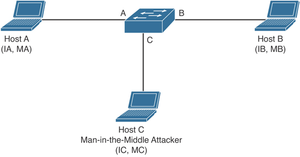
Figure 6-2 ARP Cache Poisoning
Hosts A, B, and C are connected to the switch on interfaces A, B, and C, all of which are on the same subnet. Their IP and MAC addresses are shown in parentheses; for example, Host A uses IP address IA and MAC address MA. When Host A needs to communicate to Host B at the IP layer, it broadcasts an ARP request for the MAC address associated with IP address IB. When the switch and Host B receive the ARP request, they populate their ARP caches with an ARP binding for a host with the IP address IA and a MAC address MA; for example, IP address IA is bound to MAC address MA. When Host B responds, the switch and Host A populate their ARP caches with a binding for a host with the IP address IB and the MAC address MB.
Host C can poison the ARP caches of the switch for Host A and Host B by broadcasting forged ARP responses with bindings for a host with an IP address of IA (or IB) and a MAC address of MC. Hosts with poisoned ARP caches use the MAC address MC as the destination MAC address for traffic intended for IA (or IB). This means that Host C intercepts that traffic. Because Host C knows the true MAC addresses associated with IA and IB, it can forward the intercepted traffic to those hosts by using the correct MAC address as the destination. Host C has inserted itself into the traffic stream from Host A to Host B, which is the topology of the classic man-in-the middle attack.
Dynamic ARP inspection (DAI) is a security feature that validates ARP packets in a network. DAI intercepts, logs, and discards ARP packets with invalid IP-to-MAC address bindings. This capability protects the network from some man-in-the-middle attacks.
DAI determines the validity of an ARP packet based on valid IP-to-MAC address bindings stored in a trusted database, the DHCP snooping binding database. As described in the previous section, this database is built by DHCP snooping if DHCP snooping is enabled on the VLANs and on the switch. If the ARP packet is received on a trusted interface, the switch forwards the packet without any checks. On untrusted interfaces, the switch forwards the packet only if it is valid.
You can configure DAI to drop ARP packets when the IP addresses in the packets are invalid or when the MAC addresses in the body of the ARP packets do not match the addresses specified in the Ethernet header.
Example 6-21 provides the configuration details necessary to implement DAI to mitigate the effects of ARP spoofing attacks.
Example 6-21 Configuring Dynamic ARP Inspection (DAI)
! Enable DAI on VLAN 10
sw2(config)# ip arp inspection vlan 10
sw2(config)# exit
! Verify DAI Configuration for VLAN 10
sw2# show ip arp inspection vlan 10

Source Mac Validation      : Disabled
Destination Mac Validation : Disabled
IP Address Validation      : Disabled

 Vlan     Configuration    Operation   ACL Match          Static ACL
 ----     -------------    ---------   ---------          ----------
   10     Enabled          Inactive

 Vlan     ACL Logging      DHCP Logging      Probe Logging
 ----     -----------      ------------      -------------
   10     Deny             Deny              Off

! Configure Interface Gi1/0/24 as a Trusted DAI Interface
sw2(config)# interface Gi1/0/24
sw2(config-if)# ip arp inspection trust
sw2(config-if)# exit
sw2(config)# exit
sw2# show ip arp inspection interfaces
 Interface        Trust State     Rate (pps)    Burst Interval
 ---------------  -----------     ----------    --------------
 Gi1/0/1          Untrusted               15                 1
 Gi1/0/2          Untrusted               15                 1
! output removed for brevity
 Gi1/0/23         Untrusted               15                 1
 Gi1/0/24         Trusted               None               N/A
Network Foundation Protection
The network infrastructure primarily consists of routers and switches and their interconnecting cables. The infrastructure has to be healthy and functional if we want to be able to deliver network services reliably.
If we break a big problem down into smaller pieces, such as security and what an attacker might do, we can then focus on individual components and parts. By doing this, we make the work of implementing security less daunting. That is what Network Foundation Protection (NFP) is all about: breaking the infrastructure down into smaller components and then systematically focusing on how to secure each of those components.
The Importance of the Network Infrastructure
Many pieces and parts make up a network, and even one simple component that is not working can cause a failure of the network. If a network does not work, revenue and productivity suffer. In a nutshell, if you have vulnerabilities such as weak passwords (or no passwords), software vulnerabilities, or misconfigured devices, that leaves the door open to attackers. The impact of a down network is huge; it normally affects the workforce and other systems and customers that rely on that network. The NFP framework is designed to assist you to logically group functions that occur on the network and then focus on specific security measures you can take with each of these functions.
The Network Foundation Protection Framework
For Cisco IOS routers and switches, the Network Foundation Protection (NFP) framework is broken down into three basic planes (also called sections/areas):
Management plane: This includes the protocols and traffic that an administrator uses between his workstation and the router or switch itself. An example is using a remote management protocol such as Secure Shell (SSH) to monitor or configure the router or switch. The management plane is listed here first because until the device is configured (which occurs in the management plane), the device will not be very functional in a network. If a failure occurs in the management plane, it may result in losing the ability to manage the network device altogether.
Control plane: This includes protocols and traffic that the network devices use on their own without direct interaction from an administrator. An example is a routing protocol. A routing protocol can dynamically learn and share routing information that the router can then use to maintain an updated routing table. If a failure occurs in the control plane, a router might lose the capability to share or correctly learn dynamic routing information, and as a result might not have the routing intelligence to be able to route for the network.
Data plane: This includes traffic that is being forwarded through the network (sometimes called transit traffic). An example is a user sending traffic from one part of the network to access a server in another part of the network; the data plane represents the traffic that is either being switched or forwarded by the network devices between clients and servers. A failure of some component in the data plane results in the customer’s traffic not being able to be forwarded. Other times, based on policy, you might want to deny specific types of traffic traversing the data plane.
Interdependence
Some interdependence exists between these three planes. For example, if the control plane fails, and the router does not know how to forward traffic, this scenario impacts the data plane because user traffic cannot be forwarded. Another example is a failure in the management plane that might allow an attacker to configure devices and, as a result, could cause both a control plane and data plane failure.
Implementing NFP
You learn more about each of these three planes later in this chapter as well as in subsequent chapters dedicated to each of the three planes individually. Before that, however, Table 6-2 describes security measures you can use to protect each of the three planes.
Table 6-2 Management, Control, and Data Plane Security
Management Plane |
Control Plane |
Data Plane |
Authentication, authorization, accounting (AAA) |
Control Plane Policing (CoPP) |
Access control lists (ACLs) |
Authenticated Network Time Protocol (NTP) |
Control Plane Protection (CPPr) |
Layer 2 controls, such as private VLANs and Spanning Tree Protocol (STP) Guards |
Secure Shell (SSH) |
Authentication Routing Protocol Updates |
Cisco IOS and Cisco IOS-XE Zone-based Firewall |
Transport Layer Security (TLS) |
|
SD-WAN Security |
Protected syslog |
|
|
Simple Network Management Protocol Version 3 (SNMPv3) |
|
|
NETCONF/RESTCONF |
|
|
As you might have noticed, NFP is not a single feature but rather is a holistic approach that covers the three components (that is, planes) of the infrastructure, with recommendations about protecting each one using a suite of features you can implement across your network.
A command-line utility called auto secure implements security measures (several in each category) across all three of the planes.
When implementing the best practices described by NFP, does that mean your network is going to be up forever and not have any problems? Of course not. If the network is designed poorly, with no fault tolerance, for example, and a device fails (because of a mechanical or software failure or a physical problem or because cables were removed), if you do not have the failovers in place to continue to move traffic, your data plane is going to suffer. Other factors, such as lack of change control or an administrator accidentally putting in the incorrect configuration, are, of course, ongoing potential opportunities for the network to stop functioning.
Understanding and Securing the Management Plane
This section examines what you can do to protect management access and management protocols used on the network.
As mentioned earlier, the management plane is covered first in this discussion. After all, without a configured router (whether configured through the console port or through an IP address with a secure remote-access tool such as SSH), the network device is not much good without a working configuration that either an administrator or some other type of management system such as Cisco DNA Center has put in place. (A basic Layer 2 switch with all ports in the same VLAN would be functional, but this is unlikely to be the desired configuration for that device.)
Best Practices for Securing the Management Plane
To secure the management plane, adhere to these best practices:
Enforce password policy, including features such as maximum number of login attempts and minimum password length.
Implement role-based access control (RBAC). This concept has been around for a long time in relation to groups. By creating a group that has specific rights and then placing users in that group, you can more easily manage and allocate administrators. With RBAC, we can create a role (like a group) and assign that role to the users who will be acting in it. With the role comes the permissions and access. Ways to implement RBACs include using Access Control Server (ACS) and CLI parser views (which restrict the commands that can be issued in the specific view the administrator is in). Custom privilege level assignments are also an option to restrict what a specific user may do while operating at that custom privilege level.
Use AAA services, and centrally manage those services on an authentication server (such as the Cisco ISE). With AAA, a network router or switch can interact with a centralized server before allowing any access, before allowing any command to be entered, and while keeping an audit trail that identifies who has logged in and what commands they executed while there. Your policies about who can do what can be configured on the central server, and then you can configure the routers and switches to act as clients to the server as they make their requests, asking whether it is okay for a specific user to log in or if it is okay for a specific user to issue a specific command.
Keep accurate time across all network devices using secure Network Time Protocol (NTP).
Use encrypted and authenticated versions of SNMP, which includes Version 3 (and some features from Version 2).
Control which IP addresses are allowed to initiate management sessions with the network device.
Lock down syslog. Syslog is sent in plain text. On the infrastructure of your network, only permit this type of traffic between the network device’s IP address and the destinations that the network device is configured to send the syslog messages to. In practice, not too many people are going to encrypt syslog data, although it is better to do so. Short of doing encryption, we could use an out-of-band (OOB) method to communicate management traffic between our network devices and the management stations. An example is a separate VLAN that user traffic never goes on to, and using that separate VLAN just for the management traffic. If management traffic is sent in-band, which means the management traffic is using the same networks (the same VLANs, for instance), all management traffic needs to have encryption, either built in or protected by encryption (such as using IPsec).
Disable any unnecessary services, especially those that use User Datagram Protocol (UDP). These are infrequently used for legitimate purposes, but can be used to launch denial-of-service (DoS) attacks. Following are some services that should be disabled if they are not needed:
TCP and UDP small services
Finger
BOOTP
DHCP
Maintenance Operation Protocol (MOP)
DNS
Packet assembler/disassembler (PAD)
HTTP server and Secure HTTP (HTTPS) server
CDP
LLDP
Understanding the Control Plane
This section reviews what you can do to protect network devices in the event of attacks involving traffic directed to (nontransit traffic) the network device itself.
The route processor, the CPU on a router, can only do so much. So, whenever possible, the router is going to cache information about how to forward packets (transit packets going from one device on the network to some other device). By using cached information when a packet shows up that needs to be forwarded, the CPU has to expend little effort. Forwarding of traffic is function of the data plane, and that is what really benefits from using cached information.
So, what has that got to do with the control plane? If a packet, such as an Open Shortest Path First (OSPF) or Enhanced Interior Gateway Routing Protocol (EIGRP) routing advertisement packet, is being sent to an IP address on the router, it is no longer a transit packet that can be simply forwarded by looking up information in a route cache of some type. Instead, because the packet is addressed to the router itself, the router has to spend some CPU cycles to interpret the packet, look at the application layer information, and then potentially respond. If an attacker sends thousands of packets like these to the router, or if there is a botnet of hundreds of thousands of devices, each configured to send these types of packets to the router, the router could be so busy just processing all these requests that it might not have enough resources to do its normal work. Control plane security is primarily guarding against attacks that might otherwise negatively impact the CPU, including routing updates (which are also processed by the CPU).
Best Practices for Securing the Control Plane
You can deploy CoPP and CPPr to protect the control plane. Control Plane Policing, or CoPP, can be configured as a filter for any traffic destined to an IP address on the router itself. For instance, you can specify that management traffic, such as SSH/HTTPS/SSL and so on, can be rate-limited (policed) down to a specific level or dropped completely. This way, if an attack occurs that involves an excessive amount of this traffic, the excess traffic above the threshold set could simply be ignored and not have to be processed directly by the CPU. Another way to think of this is as applying Quality of Service (QoS) to the valid management traffic and policing to the bogus management traffic.
Control Plane Protection, or CPPr, allows for a more detailed classification of traffic (more than CoPP) that is going to use the CPU for handling. The specific sub-interfaces can be classified as follows:
Host sub-interface: Handles traffic to one of the physical or logical interfaces of the router.
Transit sub-interface: Handles certain data plane traffic that requires CPU intervention before forwarding (such as IP options).
Cisco Express Forwarding (CEF): Exception traffic (related to network operations, such as keepalives or packets with Time-to-Live [TTL] mechanisms that are expiring) that has to involve the CPU.
The benefit of CPPr is that you can rate-limit and filter this type of traffic with a more fine-toothed comb than CoPP.
Using CoPP or CPPr, you can specify which types of management traffic are acceptable at which levels. For example, you could decide and configure the router to believe that SSH is acceptable at 100 packets per second, syslog is acceptable at 200 packets per second, and so on. Traffic that exceeds the thresholds can be safely dropped if it is not from one of your specific management stations. You can specify all those details in the policy.
Routing protocol authentication is another best practice for securing the control plane. If you use authentication, a rogue router on the network will not be believed by the authorized network devices (routers). The attacker may have intended to route all the traffic through his device, or perhaps at least learn detailed information about the routing tables and networks.
Although not necessarily a security feature, Selective Packet Discard (SPD) provides the ability to prioritize certain types of packets (for example, routing protocol packets and Layer 2 keepalive messages, which are received by the route processor [RP]). SPD provides priority of critical control plane traffic over traffic that is less important or, worse yet, is being sent maliciously to starve the CPU of resources required for the RP.
Understanding and Securing the Data Plane
This section covers the methods available for implementing policy related to traffic allowed through (transit traffic) network devices.
For the data plane, this discussion concerns traffic that is going through your network device rather than to a network device. This is traffic from a user going to a server, and the router is just acting as a forwarding device. This is the data plane. The following are some of the prevalent ways to control the data plane (which may be implemented on an IOS router).
Best Practices for Protecting the Data Plane
To secure the data plane, adhere to these best practices:
Block unwanted traffic at the router. If your corporate policy does not allow TFTP traffic, just implement ACLs that deny traffic that is not allowed. You can implement ACLs inbound or outbound on any Layer 3 interface on the router. With extended ACLs, which can match based on the source and/or destination address, placing the ACL closer to the source saves resources because it denies the packet before it consumes network bandwidth and before route lookups are done on a router that is filtering inbound rather than outbound. Filtering on protocols or traffic types known to be malicious is a good idea.
Reduce the chance of DoS attacks. Techniques such as TCP Intercept and firewall services can reduce the risk of SYN-flood attacks.
Reduce spoofing attacks. For example, you can filter (deny) packets trying to enter your network (from the outside) that claim to have a source IP address that is from your internal network.
Provide bandwidth management. Implementing rate-limiting on certain types of traffic can also reduce the risk of an attack (Internet Control Message Protocol [ICMP], for example, which would normally be used in small quantities for legitimate traffic).
When possible, use an IPS to inhibit the entry of malicious traffic into the network.
Additional Data Plane Protection Mechanisms
Normally, for data plane protection we think of Layer 3 and routers. Obviously, if traffic is going through a switch, a Layer 2 function is involved, as well. Layer 2 mechanisms that you can use to help protect the data plane include the following:
Port security to protect against MAC address flooding and CAM (content-addressable memory) overflow attacks. When a switch has no more room in its tables for dynamically learned MAC addresses, there is the possibility of the switch not knowing the destination Layer 2 address (for the user’s frames) and forwarding a frame to all devices in the same VLAN. This might give the attacker the opportunity to eavesdrop.
Dynamic Host Configuration Protocol (DHCP) snooping to prevent a rogue DHCP server from handing out incorrect default gateway information and to protect a DHCP server from a starvation attack (where an attacker requests all the IP addresses available from the DHCP server so that none are available for clients who really need them).
Dynamic ARP inspection (DAI) can protect against Address Resolution Protocol (ARP) spoofing, ARP poisoning (which is advertising incorrect IP-to-MAC-address mapping information), and resulting Layer 2 man-in-the-middle attacks.
IP Source Guard, when implemented on a switch, verifies that IP spoofing is not occurring by devices on that switch.
Securing Management Traffic
Fixing a problem is tricky if you are unaware of the problem. So, this first section starts by classifying and describing management traffic and identifying some of the vulnerabilities that exist. It also identifies some concepts that can help you to protect that traffic. This chapter then provides implementation examples of the concepts discussed earlier.
What Is Management Traffic and the Management Plane?
When you first get a new router or switch, you connect to it for management using a blue rollover cable that connects from your computer to the console port of that router or switch. This is your first exposure to the concept of management traffic. By default, when you connect to a console port, you are not prompted for a username or any kind of password. By requiring a username or password, you are taking the first steps toward improving what is called the management plane on this router or switch.
The management plane includes not only configuration of a system, but also who may access a system and what they are allowed to do while they are logged in to the system. The management plane also includes messages to or from a Cisco router or switch that are used to maintain or report on the current status of the device, such as a management protocol like Simple Network Management Protocol (SNMP).
Beyond the Console Cable
Using the console cable directly connected to the console port is fairly safe. Unfortunately, it is not very convenient to require the use of a console port when you are trying to manage several devices that are located in different buildings, or even on different floors of the same building. A common solution to this problem is to configure the device with an IP address that you can then use to connect to that device remotely. It is at this moment that the security risk goes up. Because you are connecting over IP, it might be possible for an unauthorized person to also connect remotely. The management plane, if it were secure, would enable you to control who may connect to manage the box, when they may connect, what they may do, and report on anything that they did. At the same time, you want to ensure that all the packets that go between the device being managed and the computer where the administrator is sitting are encrypted so that anyone who potentially might capture the individual packets while going through the network cannot interpret the contents of the packets (which might contain sensitive information about the configuration or passwords used for access).
Management Plane Best Practices
When implementing a network, remember the following best practices. Each one, when implemented, improves the security posture of the management plane for your network. In other words, each additional best practice, when put in place, raises the level of difficulty required on behalf of the attackers to compromise your device:
Strong passwords: Whenever and wherever you use passwords, make them complex and difficult to guess. An attacker can break a password in several ways, including a dictionary and/or a brute-force attack. A dictionary attack automates the process of attempting to log in as the user, running through a long list of words (potential passwords); when one attempt fails, the attack just tries the next one (and so on). A brute-force attack does not use a list of words, but rather tries thousands or millions of possible character strings trying to find a password match (modifying its guesses progressively if it incorrectly guesses the password or stops before it reaches the boundary set by the attacker regarding how many characters to guess, with every possible character combination being tried). A tough password takes longer to break than a simple password.
User authentication and AAA: Require administrators to authenticate using usernames and passwords. This is much better than just requiring a password and not knowing exactly who the user is. To require authentication using usernames and passwords, you can use a method for authentication, authorization, and accounting (AAA). Using this, you can control which administrators are allowed to connect to which devices and what they can do while they are there, and you can create an audit trail (accounting records) to document what they actually did while they were logged in.
Login Password Retry Lockout: The Login Password Retry Lockout feature allows system administrators to lock out a local AAA user account after a configured number of unsuccessful attempts by the user to log in using the username that corresponds to the AAA user account. A locked-out user cannot successfully log in again until the user account is unlocked by the administrator.
Role-based access control (RBAC): Not every administrator needs full access to every device, and you can control this through AAA and custom privilege levels/parser views. For example, if there are junior administrators, you might want to create a group that has limited permissions. You could assign users who are junior administrators to that group; they then inherit just those permissions. This is one example of using RBAC. Another example of RBAC is creating a custom privilege level and assigning user accounts to that level. Regardless of how much access an administrator has, a change management plan for approving, communicating, and tracking configuration changes should be in place and used before changes are made.
Encrypted management protocols: When using either in-band or out-of-band management, encrypted communications should be used, such as Secure Shell (SSH) or Hypertext Transfer Protocol Secure (HTTPS). Out-of-band (OOB) management implies that there is a completely separate network just for management protocols and a different network for end users and their traffic. In-band management is when the packets used by your management protocols may intermingle with the user packets (considered less secure than OOB). Whether in-band or OOB, if a plaintext management protocol must be used, such as Telnet or HTTP, use it in combination with a virtual private network (VPN) tunnel that can encrypt and protect the contents of the packets being used for management.
Logging and monitoring: Logging is a way to create an audit trail. Logging includes not only what configuration changes have been made by administrators, but also system events that are generated by the router or switch because of some problem that has occurred or some threshold that has been reached. Determine the most important information to log and identify the appropriate logging levels to use. A logging level simply specifies how much detail to include in logging messages, and may also indicate that some less-serious logging messages do not need to be logged. Because the log messages may include sensitive information, the storage of the logs and the transmission of the logs should be protected to prevent tampering or damage. Allocate sufficient storage capacity for anticipated logging demands. Logging may be done in many different ways, and your logging information may originate from many different sources, including messages that are automatically generated by the router or switch and sent to a syslog server. A syslog server is a computer that is set up to receive and store syslog messages generated from network devices. If SNMP is used, Version 3 is recommended because of its authentication and encryption capabilities. You can use SNMP to change information on a router or switch, and you can also use it to retrieve information from the router or switch. An SNMP trap is a message generated by the router or switch to alert the manager or management station of some event.
Network Time Protocol (NTP): Use NTP to synchronize the clocks on network devices so that any logging that includes timestamps may be easily correlated. Preferably, use NTP Version 3 to leverage its ability to provide authentication for time updates. This becomes very important to correlate logs between devices in case there is ever a breach and you need to reconstruct (or prove in a court of law) what occurred.
Secure system files: Make it difficult to delete, whether accidentally or on purpose, the startup configuration files and the IOS images that are on the file systems of the local routers and switches. You can do so by using built-in IOS features discussed later in this chapter.
Password Recommendations
Using passwords is one way to restrict access to only authorized users. Using passwords alone is not as good as requiring a user ID or login name associated with the password for a user.
Here are some guidelines for password creation:
It is best to have a minimum of eight characters for a password; bigger is better. This rule can be enforced by the local router if you are storing usernames and passwords on the router in the running config. The command security passwords min-length followed by the minimum password length enforces this rule on new passwords that are created, including the enable secret and line passwords on the vty, AUX, and console 0. Preexisting passwords will still operate even if they are less than the new minimum specified by the command.
Passwords can include any alphanumeric character, a mix of uppercase and lowercase characters, and symbols and spaces. As a general security rule, passwords should not use words that may be found in a dictionary, because they are easier to break. Leading spaces in a password are ignored, but any subsequent spaces, including in the middle or at the end of a password, literally become part of that password and are generally a good idea. Another good practice is using special characters or even two different words (that are not usually associated with each other) as a passphrase when combined together. Caution should be used to not require such a complex password that the user must write it down to remember it, which increases the chance of it becoming compromised.
Passwords in a perfect environment should be fairly complex and should be changed periodically. The frequency of requiring a change in passwords depends on your security policy. Passwords changed often are less likely to be compromised.
From a mathematical perspective, consider how many possibilities someone would need to try to guess a password. If only capital letters are used, you have 26 possibilities for each character. If your password is one character long, that is 261, or 26 possible variants. If you have a two-character password, that is 262, or 676 possible variants. If you start using uppercase (26) and lowercase (26), numerals (10), and basic special characters (32), your starting set becomes 94 possible variants per character. Even if we look at using an eight-character password, that is 948, or 6,095,689,385,410,816 (6.1 quadrillion), possibilities.
Multifactor authentication and Duo. In Chapter 4, you learned that the process of authentication requires the subject to supply verifiable credentials. The credentials are often referred to as “factors.” Single-factor authentication is when only one factor is presented. The most common method of single-factor authentication is the use of passwords. Multifactor authentication is when two or more factors are presented. Multilayer authentication is when two or more of the same type of factors are presented. Data classification, regulatory requirements, the impact of unauthorized access, and the likelihood of a threat being exercised should all be considered when you’re deciding on the level of authentication required. The more factors, the more robust the authentication process. Duo Security was a company acquired by Cisco that develops a very popular multifactor authentication solution used by many small, medium, and large organizations. Duo provides protection of on-premises and cloud-based applications. This is done by both preconfigured solutions and generic configurations via RADIUS, Security Assertion Markup Language (SAML), LDAP, and more. Duo integrates with many different third-party applications, cloud services, and other solutions. Duo allows administrators to create policy rules around who can access applications and under what conditions. You can customize policies globally or per user group or application. User enrollment strategy will also inform your policy configuration. Duo Beyond subscribers can benefit from additional management within their environment by configuring a Trusted Endpoints policy to check the posture of the device that is trying to connect to the network, application, or cloud resource.
Using AAA to Verify Users
Unauthorized user access to a network creates the potential for network intruders to gain information or cause harm, or both. Authorized users need access to their network resources, and network administrators need access to the network devices to configure and manage them. In Chapter 4, you learned that AAA offers a solution for both. In a nutshell, the goal of AAA is to identify who users are before giving them any kind of access to the network, and once they are identified, only give them access to the part they are authorized to use, see, or manage. AAA can create an audit trail that identifies exactly who did what and when they did it. That is the spirit of AAA. User accounts may be kept on the local AAA database or on a remote AAA server. The local database is a fancy way of referring to user accounts that are created on the local router and are part of the running configuration.
Router Access Authentication
Note that we must choose authentication first if we want to also use authorization for a user or administrator. We cannot choose authorization for a user without knowing who that user is through authentication first.
Typically, if we authenticate an administrator, we also authorize that administrator for what we want to allow him to do. Administrators traditionally are going to need access to the CLI. When an administrator is at the CLI, that interface is provided by something called an EXEC shell. If we want to authorize the router to provide this CLI, that is a perfect example of using AAA to first authenticate the user (in this case, the administrator) and then authorize that user to get a CLI prompt (the EXEC shell) and even place the administrator at the correct privilege level. This type of access (CLI) could also be referred to as character mode. Simply think of an administrator at a CLI typing in characters to assist you in remembering that this is “character” mode. With the administrator, we would very likely authenticate his login request and authorize that administrator to use an EXEC shell. If we were using a remote ISE server for this authentication and authorization of an administrator, we would very likely use TACACS+ (between the router and the ISE server) because it has the most granular control, compared with RADIUS, which is the alternative. TACACS+ and RADIUS were both discussed in Chapter 4.
The AAA Method List
To make implementing AAA modular, we can specify individual lists of ways we want to authenticate, authorize, and account for the users. To do this, we create a method list that defines what resource will be used (such as the local database, an ISE server via TACACS+ protocol or an ISE server via RADIUS protocol, and so forth). To save time, we can create a default list or custom lists. We can create authentication method lists that define the authentication methods to use, authorization method lists that define which authorization methods to use, and accounting method lists that specify which accounting methods to use. A default list, if created, applies to the entire router or switch. A custom list, to be applied, must be first created and then specifically referenced in line or interface configuration mode. You can apply a custom list over and over again in multiple lines or interfaces. The type of the method list may be authentication, authorization, or accounting.
The syntax for a method list is as follows:
aaa type {default | list-name} method-1 [method-2 method-3 method-4]
Here, list-name is used to create a custom method list. This is the name of the list, and it is used when this list is applied to a line (such as vty lines 0 through 4). The methods (method-1, method-2, and so on) are a single list that can contain up to four methods, which are tried in order from left to right. At least one method must be specified. To use the local user database, use the local keyword. In the case of an authentication method list, methods include the following:
enable: The enable password is used for authentication. This could be a good choice as the last method in a method list. This way, if the previous methods are not available (for example, if the AAA server is down or not configured), the router times out on the first methods and eventually prompts the user for the enable secret as a last resort.
krb5: Kerberos version 5 is used for authentication.
krb5-telnet: Kerberos version 5 Telnet authentication protocol is used when using Telnet to connect to the router. This is not a secure method. Using Telnet is not recommended and should be avoided.
line: The line password (the one configured with the password command, on the individual line) is used for authentication.
local: The local username database (in the router’s running configuration) is used for authentication.
Role-Based Access Control
The concept of role-based access control (RBAC) is to create a set of permissions or limited access and assign that set of permissions to users or groups. Those permissions are used by individuals for their given roles, such as a role of administrator, a role of a help desk person, and so on. There are different ways to implement RBAC, including creating custom privilege levels and creating parser views (coming up later in this section). In either case, the custom level or view can be assigned the permissions needed for a specific function or role, and then users can use those custom privilege levels or parser views to carry out their job responsibilities on the network, without being given full access to all configuration options.
Custom Privilege Levels
When you first connect to a console port on the router, you are placed into user mode. User mode is really defined as privilege level 1. This is represented by a prompt that ends with >. When you move into privileged mode by typing the enable command, you are really moving into privilege level 15. A user at privilege level 15 has access and can issue all the commands that are attached to or associated with level 15 and below. Nearly all the configuration commands, and the commands that get us into configuration mode, are associated by default with privilege level 15.
By creating custom privilege levels (somewhere between levels 2 and 14, inclusive), and assigning commands that are normally associated with privilege level 15 to this new level, you can give this subset of new commands to the individual who either logs in at this custom level or to the user who logs in with a user account that has been assigned to that level.
Limiting the Administrator by Assigning a View
Working with individual commands and assigning them to custom privilege levels is tedious at best, and it is for that reason that this method is not used very often. So, what can be done if we need users to have a subset of commands available to them, but not all of them? You can use parser views, which are also referred to as simply “a view.” You can create a view and associate it with a subset of commands. When the user logs in using this view, that same user is restricted to only being able to use the commands that are part of his current view. You can also associate multiple users with a single view.
Encrypted Management Protocols
It is not always practical to have console access to the Cisco devices you manage. There are several options for remote access via IP connectivity, and the most common is an application called Telnet. The problem with Telnet is that it uses plain text, and anyone who gets a copy of those packets can identify our usernames and passwords used for access and any other information that goes between the administrator and the router being managed (over the management plane). One solution to this is to not use Telnet. If Telnet must be used, it should only be used out of band, or placed within a VPN tunnel for privacy, or both.
Secure Shell (SSH) provides the same functionality as Telnet, in that it gives you a CLI to a router or switch; unlike Telnet, however, SSH encrypts all the packets that are used in the session. So, with SSH, if a packet is captured and viewed by an unauthorized individual, it will not have any meaning because the contents of each packet are encrypted, and the attacker or unauthorized person will not have the keys or means to decrypt the information. The encryption provides the feature of confidentiality.
With security, bigger really is better. With SSH, Version 2 is bigger and better than Version 1. Either version, however, is better than the unencrypted Telnet protocol. When you type in ip ssh version 2 (to enable Version 2), the device may respond with “Version 1.99 is active.” This is a function of a server that runs 2.0 but also supports backward compatibility with older versions. For more information, see RFC 4253, section 5.1. You should use SSH rather than Telnet whenever possible.
For graphical user interface (GUI) management tools, use HTTPS rather than HTTP because, like SSH, it encrypts the session, which provides confidentiality for the packets in that session.
Using Logging Files
I still recall an incident on a customer site when a database server had a failed disk and was running on its backup. It was like that for weeks until they noticed a log message. If a second failure had occurred, the results would have been catastrophic. Administrators should, on a regular basis, analyze logs, especially from their routers, in addition to logs from other network devices. Logging information can provide insight into the nature of an attack. Log information can be used for troubleshooting purposes. Viewing logs from multiple devices can provide event correlation information (that is, the relationship between events occurring on different systems). For proper correlation of events, accurate time stamps on those events are important. Accurate time can be implemented through Network Time Protocol (NTP).
Cisco network infrastructure devices can send log output to a variety of destinations, including the following:
Console: A router’s console port can send log messages to an attached terminal (such as your connected computer, running a terminal emulation program).
vty lines: Virtual tty (vty) connections (used by SSH and Telnet connections) can also receive log information at a remote terminal (such as an SSH or Telnet client). However, the terminal monitor command should be issued to cause log messages to be seen by the user on that vty line.
Buffer: When log messages are sent to a console or a vty line, those messages are not later available for detailed analysis. However, log messages can be stored in router memory. This “buffer” area can store messages up to the configured memory size, and then the messages are rotated out, with the first in being the first to be removed (otherwise known as first in, first out [FIFO]). When the router is rebooted, these messages in the buffer memory are lost.
SNMP server: When configured as an SNMP device, a router or switch can generate log messages in the form of SNMP traps and send them to an SNMP manager (server).
Syslog server: A popular choice for storing log information is a syslog server, which is easily configured and can store a large volume of logs. Syslog messages can be directed to one or more syslog servers from the router or switch.
A syslog logging solution consists of two primary components: syslog servers and syslog clients. A syslog server receives and stores log messages sent from syslog clients such as routers and switches.
Not all syslog messages are created equal. Specifically, they have different levels of severity. Table 6-3 lists the eight levels of syslog messages. The higher the syslog level, the more detailed the logs. Keep in mind that more-detailed logs require a bit more storage space, that syslog messages are transmitted in clear text, and that the higher levels of syslog logging consume higher amounts of CPU processing time. For these reasons, you should take care when logging to the console at the debugging level.
Table 6-3 Syslog Severity Levels
Level |
Name |
Description |
0 |
Emergencies |
System is unusable. |
1 |
Alerts |
Immediate action needed. |
2 |
Critical |
Critical conditions. |
3 |
Error |
Error conditions. |
4 |
Warnings |
Warning conditions. |
5 |
Notifications |
Normal, but significant conditions. |
6 |
Informational |
Informational messages. |
7 |
Debugging |
Highly detailed information based on debugging that is turned on. |
The syslog log entries contain timestamps, which are helpful in understanding how one log message relates to another. The log entries include severity level information in addition to the text of the syslog messages. Having synchronized time on the routers and including timestamps in the syslog messages make correlation of the syslog messages from multiple devices more meaningful.
Understanding NTP
Network Time Protocol (NTP) uses UDP port 123, and it allows network devices to synchronize their time. Ideally, they would synchronize their time to a trusted time server. You can configure a Cisco router to act as a trusted NTP server for the local network, and in the same way, that trusted NTP server (Cisco router) could turn around and be an NTP client to a trusted NTP server either on the Internet or reachable via network connectivity. NTP Version 3 supports cryptographic authentication between NTP devices, and for this reason its use is preferable over any earlier versions.
One benefit of having reliable synchronized time is that log files and messages generated by the router can be correlated. In fact, if we had 20 routers, and they were all reporting various messages and all had the same synchronized time, we could very easily correlate the events across all 20 routers if we looked at those messages on a common server such as a syslog server.
Protecting Cisco IOS, Cisco IOS-XE, Cisco IOS-XR, and Cisco NX-OS Files
Similar to the computers we use every day, a router also uses an operating system. The traditional Cisco operating system on the router is called IOS, or sometimes classic IOS. However, the newer operating system for enterprise routers is Cisco IOS-XE, for service provider routers it is Cisco IOS-XR, and for data center infrastructure devices it is NX-OS. For the purpose of this section, we will refer to all of them as “IOS.”
When a router first boots, it performs a power-on self-test and then looks for an image of IOS on the flash. After loading the IOS into RAM, the router then looks for its startup configuration. If for whatever reason an IOS image or the startup configuration cannot be found or loaded properly, the router will effectively be nonfunctional as far as the network is concerned.
To help protect a router from accidental or malicious tampering of the IOS or startup configuration, Cisco offers a resilient configuration feature. This feature maintains a secure working copy of the router IOS image and the startup configuration files at all times. Once the feature is enabled, the administrator cannot disable it remotely (but can if connected directly on the console). The secure files are referred to as a “secure bootset.”
Implementing Security Measures to Protect the Management Plane
Let’s look at some practical examples of implementing infrastructure security best practices. It requires both the understanding and implementation of these best practices to secure your networks.
Implementing Strong Passwords
The privileged EXEC secret (the one used to move from user mode to privileged mode) should not match any other password that is used on the system. Many of the other passwords are stored in plain text (such as passwords on the vty lines). If an attacker discovers these other passwords, he might try to use them to get into privileged mode, and that is why the enable secret should be unique. Service password encryption scrambles any plaintext passwords as they are stored in the configuration. This is useful for preventing someone who is looking over your shoulder from reading a plaintext password that is displayed in the configuration on the screen. Any new plaintext passwords are also scrambled as they are stored in the router’s configuration. Example 6-22 shows the use of strong passwords.
Example 6-22 Using Strong Passwords
! Use the "secret" keyword instead of the "password" for users

! This will create a secured password in the configuration by default
! The secret is hashed using the MD5 algorithm as it is stored in the
! configuration
R1(config)# username admin secret CeyeSc01$24

! At a minimum, require a login and password for access to the console port
! Passwords on lines, including the console, are stored as plain text, by
! default, in the configuration
R1(config)# line console 0
R1(config-line)# password k4(1fmMsS1#
R1(config-line)# login
R1(config-line)# exit

! At a minimum, require a login and password for access to the vty lines which
! is where remote users connect when using Telnet
! Passwords on lines, including the vty lines, are stored as plain text, by
! default, in the configuration
R1(config)# line vty 0 4
R1(config-line)# password 8wT1*eGP5@
R1(config-line)# login

! At a minimum, require a login and password for access to the AUX line
! and disable the EXEC shell if it will not be used
R1(config-line)# line aux 0
R1(config-line)# no exec
R1(config-line)# password 1wT1@ecP27
R1(config-line)# login
R1(config-line)# exit

! Before doing anything else, look at the information entered.
R1(config)# do show run | include username
username admin secret 5 $1$XJdX$9hqvG53z3lesP5BLOqggO.
R1(config)#
R1(config)# do show run | include password
no service password-encryption
 password k4(1fmMsS1#
 password 8wT1*eGP5@
 password 1wT1@ecP27
R1(config)#

! Notice that we cannot determine the admin user's password, since
! it is automatically hashed using the MD5 algorithm because of using
! the secret command, however, we can still see all the other plain text
! passwords.

! Encrypt the plain text passwords so that someone reading the configuration
! won't know what the passwords are by simply looking at the configuration.
R1(config)# service password-encryption

! Verify that the plain text passwords configured are now scrambled due to the
! command "service password-encryption"
R1(config)# do show run | begin line
line con 0
 password 7 04505F4E5E2741631A2A5454
 login
line aux 0
 no exec
 login
 password 7 075E36781F291C0627405C
line vty 0 4
 password 7 065E18151D040C3E354232
 login
!
end
User Authentication with AAA
In Chapter 4, you learned details about AAA and identity management. Example 6-23 shows the use of AAA method lists, both named and default.
Example 6-23 Enabling AAA Services and Working with Method Lists
! Enable aaa features, if not already present in the running configuration

R1(config)# aaa new-model

! Identify a AAA server to be used, and the password it is expecting with
! requests from this router. This server would need to be reachable and
! configured as a TACACS+ server to support R1's requests

R1(config)# tacacs-server host 10.8.4.1
R1(config)# tacacs-server key ToUgHPaSsW0rD-1#7

! configure the default method list for the authentication of character
! mode login (where the user will have access to the CLI)
! This default method list, created below has two methods listed "local"
! and "enable"
! This list is specifying that the local database (running-config) will
! be used first to look for the username.  If the username isn't in the
! running-config, then it will go to the second method in the list.
! The second method of "enable" says that if the user account isn't found
! in the running config, then to use the enable secret to login.
! This default list will apply to all SSH, Telnet, vty, AUX and Console
! sessions unless there is another (different) custom method list that is
! created and directly applied to one of those lines.

R1(config)# aaa authentication login default local enable

! The next authentication method list is a custom authentication
! method list named MY-LIST-1.This method list says that the first attempt
! to verify the user's name and password should be done through one of the
! tacacs servers (we have only configured one so far), and then if the server
! doesn't respond, use the local database (running-config), and if the
! username isn't in the running configuration to then use the enable secret
! for access to the device.  Note: this method list is not used until
! applied to a line elsewhere in the configuration, i.e. the default list
! configured previously is used unless MY-LIST-1 is specifically configured.

R1(config)# aaa authentication login MY-LIST-1 group tacacs local enable

! These next method lists are authorization method lists.
! We could create a default one as well, using the key
! word "default" instead of a name.    These custom method lists for
! authorization won't be used until we apply them
! elsewhere in the configuration, such as on a VTY line.
! The first method list called TAC1 is an authorization
! method list for all commands at user mode (called privilege level 1).
! The second method list called TAC15 is an
! authorization method list for commands at level 15 (privileged exec mode).
! If these method lists are applied to a line, such as the
! console or VTY lines, then before any commands
! are executed at user or privileged mode, the router will check
! with an ISE server that is one of the "tacacs+" servers, to see if the user
! is authorized to execute the command. If a tacacs+ server isn't
! reachable, then the router will use its own database of users (the local
! database) to determine if the user trying to issue the command
! is at a high enough privilege level to execute the command.

R1(config)# aaa authorization commands 1 TAC1 group tacacs+ local
R1(config)# aaa authorization commands 15 TAC15 group tacacs+ local

! The next 2 method lists are accounting method lists that will record the
! commands issued at level 1 and 15 if the lists are applied to a line, and
! if an administrator connects to this device via that line.
! Accounting method lists can have multiple methods but can't log to the
! local router.

R1(config)# aaa accounting commands 1 TAC-act1 start-stop group tacacs+
R1(config)# aaa accounting commands 15 TAC-act15 start-stop group tacacs+

! Creating a user with level 15 access on the local router is a good idea,
! in the event the ISE server can't be
! reached, and a backup method has been specified as the local database.

R1(config)# username admin privilege 15 secret 4Je7*1swEsf

! Applying the named method lists is what puts them in motion.
! By applying the method lists to the vty lines
! any users connecting to these lines will be authenticated by the
! methods specified by the lists that are applied
! and also accounting will occur, based on the lists that are applied.
R1(config)# line vty 0 4
R1(config-line)# login authentication MY-LIST-1
R1(config-line)# authorization commands 1 TAC1
R1(config-line)# authorization commands 15 TAC15
R1(config-line)# accounting commands 1 TAC-act1
R1(config-line)# accounting commands 15 TAC-act15

! Note: on the console and AUX ports, the default list will be applied,
! due to no custom method list being applied
! directly to the console or AUX ports.
Using debug as a tool to verify what you think is happening is a good idea. In Example 6-24 we review and apply AAA and perform a debug verification.
Example 6-24 Another Example of Creating and Applying a Custom Method List to vty Lines
! Creating the method list, which in this example has 3 methods.

! First the local database
! if the username exists in the configuration, and if not
! then the enable secret (if configured),  and if not then no
! authentication required
! (none)
R2(config)# aaa authentication login MY-AUTHEN-LIST-1 local enable none

! Applying the method list to the vty lines 0-4
R2(config)# line vty 0 4
R2(config-line)# login authentication MY-AUTHEN-LIST-1
R2(config-line)# exit

! Creating a local username in the local database (running-config)
R2(config)# username omar secret s0m3passwd!

! Setting the password required to move from user mode to privileged mode
R2(config)# enable secret S0mecisc0!enablePAssWD
R2(config)# interface loopback 0

! Applying an IP address to test a local telnet to this same local router
! Not needed if the device has another local IP address that is in use
R2(config-if)# ip address 10.2.2.2 255.255.255.0
R2(config-if)# exit

! Enable logging so we can see results of the upcoming debug
R2(config)# logging buffered 7
R2(config)# end

! Enabling debug of aaa authentication, so we can see what the router is
! thinking regarding aaa authentication
R2# debug aaa authentication
AAA Authentication debugging is on

R2# clear log
Clear logging buffer [confirm]

! Telnet to our own address
R2# telnet 10.2.2.2
Trying 10.2.2.2 ... Open

User Access Verification
Username: omar
AAA/BIND(00000063): Bind i/f
AAA/AUTHEN/LOGIN (00000063): Pick method list 'MY-AUTHEN-LIST-1'
Password: ***** password not shown when typing it in

R2>

! Below, after issuing the who command, we can see that bob is connected via line
! vty 0, and that from the debug messages above
! the correct authentication list was used.
R2>who
    Line       User       Host(s)              Idle       Location
   0 con 0                2.2.2.2              00:00:00
*  2 vty 0     bob        idle                 00:00:00 2.2.2.2
R2> exit

! If we exit back out, and remove all the users in the local database,
! (including omar) then the same login authentication will fail on the first
! method of the "local" database (no users there), and will go to the second
! method in the list, which is "enable", meaning use the enable secret if
! configured.

! As soon as I supply a username, the router discovers that there are no
! usernames configured in running configuration (at least none that match
! the user who is trying to login), and fails on the first method "local" in the list.
! It then tries the next method of just caring about the enable secret.

R2# telnet 10.2.2.2
Trying 10.2.2.2 ... Open
User Access Verification

AAA/BIND(00000067): Bind i/f
AAA/AUTHEN/LOGIN (00000067): Pick method list 'MY-AUTHEN-LIST-1'

! Note: omar is not a configured user in the local database on the router
Username: omar
Password: **** not shown while typing.
! This is the enable secret that was previously set.
AAA/AUTHEN/ENABLE(00000067): Processing request action LOGIN
AAA/AUTHEN/ENABLE(00000067): Done status GET_PASSWORD

R2>
AAA/AUTHEN/ENABLE(00000067): Processing request action LOGIN
AAA/AUTHEN/ENABLE(00000067): Done status PASS
R2> exit

! One more method exists in the method list we applied to the vty lines.
! If the local fails, and the enable secret fails (because neither of these
! is configured on the router), then the third method in the method list
! 'MY-AUTHEN-LIST-1' will be tried. The third method we specified is none,
! meaning no authentication required, come right in.  After removing the
! enable secret, we try once more.

R2# telnet 10.2.2.2
Trying 10.2.2.2 ... Open

User Access Verification

AAA/BIND(00000068): Bind i/f
AAA/AUTHEN/LOGIN (00000068): Pick method list 'MY-AUTHEN-LIST-1'
Username: doesn't matter
R2>
AAA/AUTHEN/ENABLE(00000068): Processing request action LOGIN
AAA/AUTHEN/ENABLE(00000068): Done status FAIL - secret not configured
R2>
! No password was required.   All three methods of the method lists were
! tried.
! The first two methods failed, and the third of "none" was accepted.
Using the CLI to Troubleshoot AAA for Cisco Routers
One tool you can use when troubleshooting AAA on Cisco routers is the debug command. You may use three separate debug commands to troubleshoot the various aspects of AAA:
debug aaa authentication: Use this command to display debugging messages for the authentication functions of AAA.
debug aaa authorization: Use this command to display debugging messages for the authorization functions of AAA.
debug aaa accounting: Use this command to display debugging messages for the accounting functions of AAA.
Each of these commands is executed from privileged EXEC mode. To disable debugging for any of these functions, use the no form of the command, such as no debug aaa authentication. If you want to disable all debugging, issue the undebug all command.
Example 6-25 shows an example of debugging login authentication, EXEC authorization, and commands at level 15 authorization. As shown in the example, you can use debug not only for verification, as in the preceding example, but also as a troubleshooting method.
Example 6-25 Using debug Commands
! R4 will have a loopback, so we can telnet to ourselves to test

R4(config-if)# ip address 10.4.4.4 255.255.255.0
R4(config-if)# exit

! Local user in the database has a privilege level of 15
R4(config)# username admin privilege 15 secret cisco1sNotAGoodPasswd!

! This method list, if applied to a line, will specify local authentication
R4(config)# aaa authentication login AUTHEN_Loc local

! This next method list, if applied to a line, will require authorization
! before giving the administrator an exec shell.   If the user has a valid
! account in the running configuration, the exec shell will be created for
! the authenticated
! user, and it will place the user in their privilege level automatically

R4(config)# aaa authorization exec AUTHOR_Exec_Loc local

! This method list, if applied to a line, will require authorization for
! each and every level 15 command issued.   Because the user is at
! privilege level 15 the router will say "yes" to any level 15 commands
! that may be issued by the user
R4(config)# aaa authorization commands 15 AUTHOR_Com_15 local

! Next we will apply the 3 custom method lists to vty lines 0-4, so that
! when anyone connects via these vty lines, they will be subject to the
! login authentication, the exec authorization, and the level 15 command
! authorizations for the duration of their session.

R4(config)# line vty 0 4
R4(config-line)# login authentication AUTHEN_Loc
R4(config-line)# authorization exec AUTHOR_Exec_Loc
R4(config-line)# authorization commands 15 AUTHOR_Com_15
R4(config-line)# exit
R4(config)#
R4(config)# do debug aaa authentication
AAA Authentication debugging is on
R4(config)# do debug aaa authorization
AAA Authorization debugging is on
R4(config)# exit

! Now test to see it all in action.
R4# telnet 10.4.4.4
Trying 10.4.4.4 ... Open
User Access Verification

Username: admin
Password: ****** (password not displayed when entering)

! The router used the login authentication list we specified
AAA/BIND(00000071): Bind i/f
AAA/AUTHEN/LOGIN (00000071): Pick method list 'AUTHEN_Loc'

! The router picked the authorization list specified for the exec shell
AAA/AUTHOR (0x71): Pick method list 'AUTHOR_Exec_Loc'
AAA/AUTHOR/EXEC(00000071): processing AV cmd=
AAA/AUTHOR/EXEC(00000071): processing AV priv-lvl=15
AAA/AUTHOR/EXEC(00000071): Authorization successful

! It picked the command level 15 authorization list, when we issued the
! configure terminal command, which is a level 15 command.
R4# config t
Enter configuration commands, one per line.  End with CNTL/Z.
R4(config)#
AAA/AUTHOR: auth_need : user= 'admin' ruser= 'R4' rem_addr= '10.4.4.4' priv= 15 list=
'AUTHOR_Com_15' AUTHOR-TYPE= 'command'
AAA: parse name=tty2 idb type=-1 tty=-1
AAA: name=tty2 flags=0x11 type=5 shelf=0 slot=0 adapter=0 port=2 channel=0
AAA/MEMORY: create_user (0x6A761F34) user='admin' ruser='R4' ds0=0 port='tty2'
rem_addr='10.4.4.4' authen_type=ASCII service=NONE priv=15 initial_task_id='0',
vrf= (id=0)
tty2 AAA/AUTHOR/CMD(1643140100): Port='tty2' list='AUTHOR_Com_15' service=CMD
AAA/AUTHOR/CMD: tty2(1643140100) user='admin'
tty2 AAA/AUTHOR/CMD(1643140100): send AV service=shell
tty2 AAA/AUTHOR/CMD(1643140100): send AV cmd=configure
tty2 AAA/AUTHOR/CMD(1643140100): send AV cmd-arg=terminal
tty2 AAA/AUTHOR/CMD(1643140100): send AV cmd-arg=<cr>
tty2 AAA/AUTHOR/CMD(1643140100): found list "AUTHOR_Com_15"
tty2 AAA/AUTHOR/CMD(1643140100): Method=LOCAL
AAA/AUTHOR (1643140100): Post authorization status = PASS_ADD
AAA/MEMORY: free_user (0x6A761F34) user='admin' ruser='R4' port='tty2'
rem_addr='10.4.4.4' authen_type=ASCII service=NONE priv=15 vrf= (id=0)
R4(config)#
! It made a big splash, with lots of debug output, but when you boil it all
! down it means the user was authorized to issue the configure terminal
! command.
There is also a test aaa command that is very useful when verifying connectivity with a remote ISE server.
RBAC Privilege Level/Parser View
You may implement RBAC through AAA, with the rules configured on an ISE server, but you may implement it in other ways, too, including creating custom privilege levels and having users enter those custom levels where they have a limited set of permissions, or creating a parser view (also sometimes simply called a view), which also limits what the user can see or do on the Cisco device. Each option can be tied directly to a username so that once users authenticate, they may be placed at the custom privilege level or in the view that is assigned to them.
Let’s implement a custom privilege level first, as shown in Example 6-26. The example includes explanations throughout.
Example 6-26 Creating and Assigning Commands to a Custom Privilege Level
! By default,  we use privilege level 1 (called user mode), and privilege
! level 15 (called privileged mode).   By creating custom levels, (between
! 1-15) and assigning commands to those levels, we are creating custom
! privilege levels.
! A user connected at level 8, would have any of the new commands -
! associated with level 8, as well as any commands that have been custom
! assigned or defaulted to levels 8 and below.    A user at level 15 has
! access to all commands at level 15 and below.
! This configuration assigns the command "configure terminal" to privilege
! level 8
R2(config)# privilege exec level 8 configure terminal

! This configuration command assigns the password for privilege level 8
! The keyword "password" could be used instead of secret, but is less secure
! as the "password" doesn't use the MD5 hash to protect the password.
! The "0" before the password implies that we are inputting a non-hashed
! (to begin with) password.  The system will hash this for us, because we
! used the enable "secret" keyword.
R2(config)# enable secret level 8 0 NewPa5s123&
R2(config)# end
R2#
%SYS-5-CONFIG_I: Configured from console by console

! To enter this level, use the enable command, followed by the level you want
! to enter.   If no level is specified, the default level is 15.

R2# disable

! Validate that user mode is really privilege level 1
R2> show privilege

Current privilege level is 1
! Context sensitive help shows that we can enter a level number after the
! word enable

R2> enable ?
  <0-15>  Enable level
  view    Set into the existing view
  <cr>

R2> enable 8
Password: [NewPa5s123&]
! note: password doesn't show when typing it in

R2# show privilege
Current privilege level is 8
! We can go into configuration mode, because "configure terminal" is at our
! level

R2# configure terminal

Enter configuration commands, one per line.  End with CNTL/Z.
! Notice we don't have further ability to configure the router, because
! level 8 doesn't include the interface configuration or other router -
! configuration commands.
R2(config)# ?
Configure commands:
  beep     Configure BEEP (Blocks Extensible Exchange Protocol)
  call     Configure Call parameters
  default  Set a command to its defaults
  end      Exit from configure mode
  exit     Exit from configure mode
  help     Description of the interactive help system
  license  Configure license features
  netconf  Configure NETCONF
  no       Negate a command or set its defaults
  oer      Optimized Exit Routing configuration submodes
  sasl     Configure SASL
  wsma     Configure Web Services Management Agents
If we are requiring login authentication, we can associate a privilege level with a given user account, and then when users authenticate with their username and password, they will automatically be placed into their appropriate privilege level. Example 6-27 shows an example of this.
Example 6-27 Creating a Local User and Associating That User with Privilege Level 8 and Assigning Login Requirements on the vty Lines
! Create the user account in the local database (running-config) and
! associate that user with the privilege level you want that user to use.
R2(config)# username Bob privilege 8 secret Cisco1231sAlsoNotAG00dPasswd
R2(config)# line vty 0 4

! "login local" will require a username and password for access if the "aaa
! new-model" command is not present.   If we have set the aaa new-model,
! then we would also want to create a default or named method list that
! specifies we want to use the local database for authentication.
R2(config-line)# login local

! Note:  Once bob logs in, he would have access to privilege level 8 and
! below, (including all the normal show commands at level 1)
Implementing Parser Views
To restrict users without having to create custom privilege levels, you can use a parser view, also referred to as simply “a view.” A view can be created with a subset of privilege level 15 commands, and when the user logs in using this view, that same user is restricted to only being able to use the commands that are part of his current view.
To create a view, an enable secret password must first be configured on the router. AAA must also be enabled on the router (aaa new-model command).
Example 6-28 shows the creation of a view.
Example 6-28 Creating and Working with Parser Views
! Set the enable secret, and enable aaa new-model
! (unless already in place)
R2(config)# enable secret aBc!2#&iU
R2(config)# aaa new-model
R2(config)# end

! Begin the view creation process by entering the "default" view, using the
! enable secret
R2# enable view
Password: ***** note password not shown when typed

R2#
%PARSER-6-VIEW_SWITCH: successfully set to view 'root'.
R2# configure terminal

! As the administrator in the root view, create a new custom view
R2(config)# parser view New_VIEW
%PARSER-6-VIEW_CREATED: view 'New_VIEW' successfully created.

! Set the password required to enter this new view
R2(config-view)# secret New_VIEW_PW

! Specify which commands you want to include as part of this view.
! commands "exec" refer to commands issued from the command prompt
! commands "configure" refer to commands issued from privileged mode
R2(config-view)# commands exec include ping
R2(config-view)# commands exec include all show
R2(config-view)# commands exec include configure

! This next line adds the ability to configure "access-lists" but nothing
! else
R2(config-view)# commands configure include access-list
R2(config-view)# exit
R2(config)# exit

! Test the view, by going to user mode, and then back in using the new view
R2# disable
R2>enable view New_VIEW
Password: [New_VIEW_PW] Password not shown when typed in

! Console message tells us that we are using the view
%PARSER-6-VIEW_SWITCH: successfully set to view 'New_VIEW'.

! This command reports what view we are currently using
R2# show parser view
Current view is 'New_VIEW'

! We can verify that the commands assigned to the view work.
! Note: we only assigned configure, not configure terminal so we have to
! use the configure command, and then tell the router we are configuring
! from the terminal.   We could have assigned the view "configure terminal"
! to avoid this.
R2# configure terminal
Enter configuration commands, one per line.  End with CNTL/Z.

! Notice that the only configuration options we have are for access-list,
! per the view
R2(config)# ?
Configure commands:
  access-list  Add an access list entry
  do           To run exec commands in config mode
  exit         Exit from configure mode
We could also assign this view to a user account so that when users log in with their username and password, they are automatically placed into their view, as shown in Example 6-29.
Example 6-29 Associating a User Account with a Parser View
R2(config)# username Lois view New_VIEW secret Cisco1231sNotAG00dPasswd
SSH and HTTPS
Because Telnet sends all of its packets as plain text, it is not secure. SSH allows remote management of a Cisco router or switch, but unlike Telnet, SSH encrypts the contents of the packets to protect them from being interpreted if they fall into the wrong hands.
To enable SSH on a router or switch, the following items need to be in place:
Hostname other than the default name of router.
Domain name.
Generating a public/private key pair, used behind the scenes by SSH.
Requiring user login via the vty lines, instead of just a password. Local authentication or authentication using an ISE server are both options.
Having at least one user account to log in with, either locally on the router or on an ISE server.
Example 6-30 shows how to implement these components, along with annotations and examples of what happens when the required parts are not in place. If you have a nonproduction router or switch handy, you might want to follow along.
Example 6-30 Preparing for SSH
! To create the public/private key pair used by SSH, we would issue the
! following command.   Part of the key pair will be the hostname and the
! domain name.
! If these are not configured first, the crypto key generate command will
! tell you as shown in the next few lines.
Router(config)# crypto key generate rsa
% Please define a hostname other than Router.
Router(config)# hostname R1
R1(config)# crypto key generate rsa
% Please define a domain-name first.
R1(config)# ip domain-name cisco.com

! Now with the host and domain name set, we can generate the key pair
R1(config)# crypto key generate rsa
The name for the keys will be: R1.cisco.com

Choose the size of the key modulus in the range of 360 to 2048 for your
  General Purpose Keys. Choosing a key modulus greater than 512 may take
  a few minutes.

! Bigger is better with cryptography, and we get to choose the size for the
! modulus.
! The default is 512 on many systems, but you would want to choose 1024 or
! more to improve security. SSH has several flavors, with version 2 being
! more secure than version 1. To use version 2, you would need at least a
! 1024 size for the key pair.
How many bits in the modulus [512]: 1024
% Generating 1024 bit RSA keys, keys will be non-exportable...

R1(config)#
%SSH-5-ENABLED: SSH 1.99 has been enabled
! Note the "1.99" is based on the specifications for SSH from RFC 4253
! which indicate that an SSH server may identify its version as 1.99 to
! identify that it is compatible with current and older versions of SSH.

! Create a user in the local database
R1(config)# username omar secret Ci#kRk*ks

! Configure the vty lines to require user authentication
R1(config)# line vty 0 4
R1(config-line)# login local

! Alternatively, we could do the following for the requirement of user
! authentication
! This creates a method list which points to the local database, and then
! applies that list to the VTY lines
R1(config)# aaa new-model
R1(config)# aaa authentication login Omar-List-1 local
R1(config)# line vty 0 4
R1(config-line)# login authentication Omar-List-1

! To test this we could SSH to ourselves from the local machine, or from
! another router that has IP connectivity to this router.

R1# ssh ?
  -c    Select encryption algorithm
  -l    Log in using this user name
  -m    Select HMAC algorithm
  -o    Specify options
  -p    Connect to this port
  -v    Specify SSH Protocol Version
  -vrf  Specify vrf name
  WORD  IP address or hostname of a remote system

! Note: one of our local IP addresses is 10.1.0.1
R1# ssh -l omar 10.1.0.1

Password: <password for Omar goes here>

R1>
! to verify the current SSH session(s)
R1> show ssh
Connection Version Mode Encryption  Hmac       State            Username
0          2.0     IN   aes128-cbc  hmac-sha1  Session started  omar
0          2.0     OUT  aes128-cbc  hmac-sha1  Session started  omar
%No SSHv1 server connections running.
R1>
Perhaps you want to manage a router via HTTPS. If so, you can implement HTTPS functionality, as shown in Example 6-31.
Example 6-31 Preparing for HTTPS
! Enable the SSL service on the local router.   If it needs to generate
! keys for this feature, it will do so on its own in the background.
R1(config)# ip http secure-server

! Specify how you want users who connect via HTTPS to be authenticated.
R1(config)# ip http authentication ?
  aaa     Use AAA access control methods
  enable  Use enable passwords
  local   Use local username and passwords

R1(config)# ip http authentication local

! If you are using the local database, make sure you have at least one user
! configured in the running-config so that you can login.  To test, open
! a browser to HTTPS://a.b.c.d where a.b.c.d is the IP address on the
! router.
Implementing Logging Features
Logging is important as a tool for discovering events that are happening in the network and for troubleshooting. Correctly configuring logging so that you can collect and correlate events across multiple network devices is a critical component for a secure network.
Configuring Syslog Support
Example 6-32 shows a typical syslog message and how to control what information is included with the message.
Example 6-32 Using Service Timestamps with Syslog Events
R4(config)# interface Gi0/0

R4(config-if)# shut
%LINK-5-CHANGED: Interface GigabitEthernet0/0, changed state to administratively down
%LINEPROTO-5-UPDOWN: Line protocol on Interface GigabitEthernet0/0,
changed state to down
R4(config-if)#

! If we add time stamps to the syslog messages, those time stamps can assist
! in correlating events that occurred on multiple devices

R4(config)# service timestamps log datetime
R4(config)# int Gi0/0
R4(config-if)# no shutdown

! These syslog messages have the date of the event, the event (just after
! the %) a description, and also the level of the event (the first event in
! the example below is level 3 with the second event being level 5).
*Sep 22 12:08:13: %LINK-3-UPDOWN: Interface GigabitEthernet0/0,
changed state to up
*Sep 22 12:08:14: %LINEPROTO-5-UPDOWN: Line protocol on
Interface GigabitEthernet0/0, changed state to up
Configuring NTP
Because time is such an important factor, you should use Network Time Protocol (NTP) to synchronize the time in the network so that events that generate messages and timestamps can be correlated.
To configure the NTP, you first need to know what the IP address is of the NTP server you will be working with, and you also want to know what the authentication key is and the key ID. NTP authentication is not required to function, but it’s a good idea to ensure that the time is not modified because of a rogue NTP server sending inaccurate NTP messages using a spoofed source IP address.
NTP supports authentication on a Cisco router because the router supports NTPv3. Example 6-33 demonstrates how to configure NTPv3 in a router. The NTP server’s IP address is 192.168.78.96 and is reachable via the GigabitEthernet0/1 interface.
Example 6-33 Using Authentication via Keys with NTPv3
ntp authentication-key 1 md5 141411050D 7
ntp authenticate
ntp trusted-key 1
ntp update-calendar
ntp server 192.168.78.96 key 1 prefer source GigabitEthernet0/1
To verify the status on this router acting as an NTP client, you could use the commands from the CLI shown in Example 6-34.
Example 6-34 Verifying Synchronization from the NTP Client
LAB-Router# show ntp status

Clock is synchronized, stratum 4, reference is 192.168.78.96
nominal freq is 250.0000 Hz, actual freq is 249.9980 Hz, precision is
2**24 reference time is D8147295.4E6FD112 (13:11:49.306 UTC Mon Feb 3 2020)
clock offset is -0.3928 msec, root delay is 83.96 msec
root dispersion is 94.64 msec, peer dispersion is 2.22 msec
loopfilter state is 'CTRL' (Normal Controlled Loop),
drift is 0.000007749 s/s, system poll interval is 64,
last update was 126 sec ago.
LAB-Router#

LAB-Router# show ntp association

  address         ref clock       st   when   poll reach  delay  offset   disp
*~192.168.78.96    208.75.89.4    3    49     64   377  1.341  -0.392  2.424
 * sys.peer, # selected, + candidate, - outlyer, x falseticker, ~ configured
LAB-Router#
Securing the Network Infrastructure Device Image and Configuration Files
If a router has been compromised, and the flash file system and NVRAM have been deleted, there could be significant downtime as the files are put back in place before restoring normal router functionality. The Cisco Resilient Configuration feature is intended to improve the recovery time by making a secure working copy of the IOS image and startup configuration files (which are referred to as the primary bootset) that cannot be deleted by a remote user.
To enable and save the primary bootset to a secure archive in persistent storage, follow Example 6-35.
Example 6-35 Creating a Secure Bootset
! Secure the IOS image

R6(config)# secure boot-image
%IOS_RESILIENCE-5-IMAGE_RESIL_ACTIVE: Successfully secured running image

! Secure the startup-config
R6(config)# secure boot-config
%IOS_RESILIENCE-5-CONFIG_RESIL_ACTIVE: Successfully secured config archive
   [flash:.runcfg-20111222-230018.ar]

! Verify the bootset
R6(config)# do show secure bootset
IOS resilience router id FTX1036A13J

IOS image resilience version 16.4 activated at 23:00:10 UTC Thu Dec 22 2011
Secure archive flash:router-164-24.bin type is image (elf) []
  file size is 60303612 bytes, run size is 60469256 bytes
  Runnable image, entry point 0x80010000, run from ram

IOS configuration resilience version 16.4 activated at
23:00:18 UTC Thu Dec 22 2019
Secure archive flash:runcfg-20111222-230018.ar type is config
configuration archive size 1740 bytes

! Note: to undo this feature, (using the "no" option in front of the command)
! you must be connected via the console.  This prevents remote users from
! disabling the feature.
Securing the Data Plane in IPv6
This book and the exam assume that you are familiar with IPv6 fundamentals. To make certain that you are, this chapter explains how IPv6 works and how to configure it, and then you learn how to develop a security plan for IPv6.
Understanding and Configuring IPv6
When compared to IPv4, both similarities and differences exist as to how IPv6 operates. The CCNP Security and CCIE Security certifications require that you know the fundamentals of IPv6, and that is the focus of this section, which first reviews IPv6 basics and then shows you how to configure it.
Why IPv6? Here are two good reasons to move to IPv6:
IPv6 has more address space available.
We are running out of public IPv4 addresses.
For more than a decade, the requirement to implement IPv6 has been threatened as imminent. The lifetime of its predecessor (IPv4) was extended more than a decade because of features such as network address translation (NAT), which enables you to hide thousands of users with private IP addresses behind a single public IP address.
With IPv6, upper-layer applications still work like you are used to with IPv4. The biggest change is that we are doing a forklift upgrade to Layer 3 of the OSI model. Along with this change, there are some modifications as to how IPv6 interacts with the rest of the protocol stack and some modifications to its procedures for participating on the network.
Table 6-4 describes a few of the notable differences and some similarities between IPv4 and IPv6.
Table 6-4 IPv4 Versus IPv6
IPv4 |
IPv6 |
32-bit (4-byte) address supports 232 (or 4,294,967,296) addresses. |
128-bit (16-byte) address supports 2128 (about 3.4 x 1038) addresses. 438 quintillion addresses per square inch of land on Earth (so a LOT!). |
You can use NAT to extend address space limitations. |
Does not support NAT by design, since it has plenty of addresses available. |
Administrators must use Dynamic Host Configuration Protocol (DHCP) or static configuration to assign IP addresses to hosts. |
Hosts can use stateless address autoconfiguration to assign an IP address to themselves, but can also use DHCP features to learn more information, such as information about DNS servers. |
IPsec support is an optional add-on concept to protect IP packets by using encryption, validating a peer, ensuring data integrity, and supporting anti-replay. |
IPsec is fully supported in IPv6. In fact, IPsec was supposed to be mandatory when using IPv6; however, IPv6 does not actually require IPsec to be enabled in order for IPv6 to work. |
An IPv4 header consists of multiple fields. |
Simplified (but larger) IPv6 header, with options for header extension as needed. |
Uses broadcasts for several functions, including Address Resolution Protocol (ARP). |
Does not use any broadcasts and does not use ARP. Instead, it uses multicast addresses and Neighbor Discovery Protocol (NDP), also called ND. ND replaces ARP. Devices can automatically discover the IPv6 network address and many other housekeeping features such as discovering any routers on the network. ND uses IPv6’s version of Internet Control Message Protocol (ICMP) as the workhorse behind most of its functions. |
Both support common Layer 4 protocols such as UDP and TCP. |
|
Both support common application layer (Layer 7) protocols (HTTP, FTP, and so on) that are encapsulated in their respective Layer 4 protocols. |
|
Both support common Layer 2 technologies, such as Ethernet and WAN standards. |
|
Both contain two parts in the IP address: the network on the left side of the address and the host part on the right side of the address. |
|
Both use a network mask to identify which part of the address is the network (on the left), indicated by the mask bits that are on (or 1), and the rest of the bits to the right represent the host part of the IPv4 or IPv6 address. |
|
The Format of an IPv6 Address
Understanding the basic format of an IPv6 address is important for certification and for the actual implementation of IPv6. Here are a few key details about IPv6 and its format:
Length: IPv6 addresses are 128 bits (16 bytes) long.
Groupings: IPv6 addresses are segmented into eight groups of four hex characters.
Separation of groups: Each group is separated by a colon (:).
Length of mask: Usually 50 percent (64 bits long) for network ID, which leaves 50 percent (also 64 bits) for interface ID (using a 64-bit mask).
IPv6 Address Types: There are three types of IPv6 addresses (global unicast addresses, link local addresses, and unique local addresses).
We can represent an IPv6 address the hard way or the easier way. The hard way is to type in every hexadecimal character for the IP address. In Example 6-36, we put in a 128-bit IPv6 address, typed in as 32 hexadecimal characters, and a 64-bit mask.
Example 6-36 An IPv6 Address Configured the Hard Way
R1(config-if)# ipv6 address 2001:0db8:0000:0000:1234:0000:0052:0001/64

! The output reflects how we could have used some shortcuts in representing
! the groups of zeros.
R1(config-if)# do show ipv6 interface brief
GigabitEthernet0/1            [up/up]
    FE80::C800:41FF:FE32:6
    2001:DB8::1234:0:52:1
R1(config-if)#
Understanding the Shortcuts
Example 6-36 shows the address being configured and the abbreviated address from the output of the show command. When inserting a group of four hexadecimal numbers, you can limit your typing a bit. For example, if any leading characters in the group are 0, you can omit them (just as the 0 in front of DB8 is in the second group from the left). In addition, if there are one or more consecutive groups of all 0s, you can input them as a double colon (::). The system knows that there should be eight groups separated by seven colons, and when it sees ::, it just looks at how many other groups are configured and assumes that the number of missing groups plus the existing groups that are configured totals eight. In the example, the first two groups of consecutive 0s are shortened in the final output. This shortcut may be done only once for any given IPv6 address. This example contains three groupings of 0s, and if you use the shortcut twice, the system will not know whether there should be four 0s after the DB8: and eight 0s (or two groups) after the 1234:, or vice versa.
Did We Get an Extra Address?
Besides the IPv6 global address configured in Example 6-36, the system automatically configured for itself a second IPv6 address known as a link-local address, which begins with FE80. A link-local address is an IPv6 address that you can use to communicate with other IPv6 devices on the same local network (local broadcast domain). If an IPv6 device wants to communicate with a device that is remote, it needs to use its global and routable IPv6 address for that (not the link-local one). To reach remote devices, you also need to have a route to that remote network or a default gateway to use to reach the remote network.
The following section covers the other types of addresses you will work with in IPv6 networks.
IPv6 Address Types
In IPv6, you must be familiar with several types of addresses. Some are created and used automatically; others you must configure manually. These address types include the following:
Link-local address: Link-local addresses may be manually configured, but if they are not, they are dynamically configured by the local host or router itself. These always begin with the characters FE80. The last 64 bits are the host ID (also referred to as the interface ID), and the device uses the modified EUI-64 format (by default) to create that. The modified EUI-64 uses the MAC address (if on Ethernet; and if not on Ethernet, it borrows the MAC address of another interface) and realizes it is only 48 bits. To get to 64 bits for the host ID, it inserts four hexadecimal characters of FFFE (which is the 16 more bits we need) and injects those into the middle of the existing MAC address to use as the 64-bit host ID. It also looks at the seventh bit from the left (of the original MAC address) and inverts it. If it is a 0 in the MAC address, it is a 1 in the host ID, and vice versa. To see an example of this, look back at Example 6-35, at the output of the show command there, focusing on the address that begins with FE80.
Loopback address: In IPv4, this was the 127 range of IP addresses. In IPv6, the address is ::1 (which is 127 0s followed by a 1).
All-nodes multicast address: In IPv6, multicasts begin with FFxx: (where the xx is some other hex number). The number 02 happens to designate a multicast address that is link-local in scope. There are other preset scopes, but you do not have to worry about them here. The IPv6 multicast group that all IPv6 devices join is FF02::1. If any device needs to send a packet/frame to all other local IPv6 devices, it can send the packet to the multicast address of FF02::1, which translates to a specific multicast Layer 2 address, and then all the devices that receive those frames continue to de-encapsulate them. If a device receives a frame, and the receiving device determines that the Layer 2 destination in the frame is not destined for itself and not destined for any multicast groups that the local device has joined, it discards the frame instead of continuing to de-encapsulate it to find out what is inside (in the upper layers).
All-routers multicast address: In addition to the multicast group address of FF02::1 that is joined by all devices configured for IPv6, routers that have had routing enabled for IPv6 also join the multicast group FF02::2. By doing so, any client looking for a router can send a request to this group address and get a response if there is a router on the local network. You might have noticed a pattern here: FF02 is just like 224.0.0.x in IPv4 multicast: 224.0.0.1 = all devices, and 224.0.0.2 = all routers.
Unicast and anycast addresses (configured automatically or manually): A global IPv6 address, unlike a link-local address, is routable and can be reached through one or more routers that are running IP routing and that have a correct routing table. Global IPv6 unicast addresses have the first four characters in the range of 2000 to 3FFF, and may be manually configured, automatically discovered by issuing a router solicitation request to a local router, or be learned via IPv6 Dynamic Host Configuration Protocol (DHCP). An anycast address can be a route or an IP address that appears more than one time in a network, and then it is up to the network to decide the best way to reach that IP. Usually, two DNS servers, if they both use the same anycast address, are functional to the users so that regardless of which DNS server that packets are forwarded to, the client gets the DNS response it needs.
Solicited-node multicast address for each of its unicast and anycast addresses: When a device has global and link-local addresses, it joins a multicast group of FF02::1:FFxx:xxxx The x characters represent the last 24 bits of the host ID being used for the addresses. If a device needs to learn the Layer 2 address of a peer on the same network, it can send out a neighbor solicitation (request) to the multicast group that the device that has that address should have joined. This is the way IPv6 avoids using broadcasts.
Multicast addresses of all other groups to which the host belongs: If a router has enabled IPv6 routing, it joins the FF02::2 group (all routers), as mentioned earlier. If a router is running RIPng (the IPv6 flavor), it joins the multicast group for RIPng, which is FF02::9, so that it will process updates sent to that group from other RIP routers. Notice again some similarities. RIPv2 in IPv4 uses 224.0.0.9 as the multicast address.
Example 6-37 shows the output for a router that has been enabled for IPv6 routing, RIPng, and has an IPv6 global address.
Example 6-37 IPv6 Interface Information
! MAC address, for reference, that is currently used on the Gi0/1
! interface
R1# show interfaces Gi0/1 | include bia
  Hardware is i82543 , address is ca00.4132.0006 (bia ca00.4132.0006)

R1# show ipv6 interface Gi0/1
GigabitEthernet0/1 is up, line protocol is up


! Link-local address, beginning with FE80::
! and using modified EUI-64 for the host ID.
! Notice that CA from the MAC address is C8 in the host ID
! due to inverting the 7th bit for the modified EUI-64 formatting
  IPv6 is enabled, link-local address is FE80::C800:41FF:FE32:6

! Global addresses have the first group range of 2000-3fff
  Global unicast address(es):
    2001:DB8::1234:0:52:1, subnet is 2001:DB8::/64


! Multicast begins with FFxx:
  Joined group address(es):

! Because we are enabled for IPv6 on this interface
    FF02::1

! Because we are enabled for IPv6 routing
    FF02::2

! Because we are enabled for RIPng
    FF02::9

! Because our link-local address ends in 32:0006
! this is a solicited node multicast group
    FF02::1:FF32:6

! Because our global address ends in 52:0001
! this is a solicited node multicast group
    FF02::1:FF52:1

<snip>
Configuring IPv6 Routing
To support multiple IPv6 networks and allow devices to communicate between those networks, you need to tell the routers how to reach remote IPv6 networks. You can do so through static routes, IPv6 routing protocols, and default routes. For the router to route any customer’s IPv6 traffic, you need to enable unicast routing for IPv6 from global configuration mode. If you fail to do this, the router can send and receive its own packets, but it will not forward packets for others, even if it has the routes in its IPv6 routing table.
IPv6 can use the new and improved flavors of these dynamic routing protocols with their versions that support IPv6:
RIP, called RIP next generation (RIPng)
OSPFv3
EIGRP for IPv6
One difference with the interior gateway routing protocols for IPv6 is that none of them support network statements. To include interfaces of the routing process, you use interface commands. For EIGRP, you also need to issue the no shutdown command in EIGRP router configuration mode. Example 6-38 shows the enabling of unicast routing and the configuring of IPv6 routing protocols.
Example 6-38 Enabling IPv6 Routing and Routing Protocols
! Enables IPv6 routing of other devices' packets

R1(config)# ipv6 unicast-routing

! Enabling all 3 IGPs on interface Gi0/1
! Note: that in a production network, we would only need 1 routing protocol
! on a given interface.   If we did have multiple identical learned routes
! the Administrative Distance (same as in IPv4) would determine which
! routing protocols would be the "best" and be placed in the routing table.
R1(config)# interface Gi0/1

! Enabling RIPng on the interface
! Simply create a new "name" for the process.  I called this one "MYRIP"
! Use the same name on all the interfaces on the local router where you
! want RIPng to be used on that same router.

R1(config-if)# ipv6 rip MYRIP enable

! Enabling OSPFv3 on the interface
! Syntax is the keywords ipv6 ospf, followed by the process ID (the process ID
! is locally assigned and can be a positive integer from 1 to 65535), then the
! area information
R1(config-if)# ipv6 ospf 1 area 0

! Enabling IPv6 EIGRP on the interface
R1(config-if)# ipv6 eigrp 1
R1(config-if)# exit

! Bringing the EIGRP routing process out of its default shutdown state
! Note: This is done in global (not interface) configuration mode.
! This is not needed for RIPng or OSPFv3.
R1(config)# ipv6 router eigrp 1
R1(config-rtr)# no shutdown

! Verify which routing protocols are running
R1# show ipv6 protocol
IPv6 Routing Protocol is "connected"
IPv6 Routing Protocol is "rip MYRIP"
  Interfaces:
    GigabitEthernet0/1
  Redistribution:
    None
IPv6 Routing Protocol is "ospf 1"
  Interfaces (Area 0):
    GigabitEthernet0/1
  Redistribution:
    None
IPv6 Routing Protocol is "eigrp 1"
  EIGRP metric weight K1=1, K2=0, K3=1, K4=0, K5=0
  EIGRP maximum hopcount 100
  EIGRP maximum metric variance 1
  Interfaces:
    GigabitEthernet0/1
  Redistribution:
    None
  Maximum path: 16
  Distance: internal 90 external 170
The command show ipv6 route outputs the IPv6 routes the router knows how to reach, including the ones learned through dynamic routing protocols.
Moving to IPv6
Moving to IPv6 will be more of a transition or migration than a one-time event. As such, there are mechanisms in place to support coexistence between IPv4 and IPv6, including the ability for a router or network device to run both protocol stacks at the same time, and the ability to perform tunneling. A tunneling example would be when there are two isolated portions of the network that want to run IPv6, and between them, there is a big patch of IPv4 only. Tunneling would take the IPv6 packets and re-encapsulate them into IPv4 for transport across the IPv4 portion of the network. At the other end of the tunnel, the router would de-encapsulate the IPv6 from the IPv4 shell and then continue forwarding the IPv6 packet on toward its final destination.
Developing a Security Plan for IPv6
Most security risks associated with the older IPv4 are the same security risks associated with the newer IPv6. Now what does that mean to you? It means that you need to make sure you have considered and implemented security controls to address both protocol stacks. This section discusses many security threats common to both IPv4 and IPv6 (and some specific to IPv6) and how to address them.
Best Practices Common to Both IPv4 and IPv6
For both protocol stacks, here are some recommended best practices—a great place to start your network configuration:
Physical security: Keep the room where the router is housed free (safe) from electrostatic and magnetic interference. It should also be temperature and humidity controlled. There should be controlled and logged access to that physical room. Redundant systems for electricity that feed into the routers are part of this, as well.
Device hardening: Disable services that are not in use and features and interfaces that are not in use. A great reference for these best practices is the Cisco Guide to Harden Cisco IOS Devices (http://www.cisco.com/c/en/us/support/docs/ip/access-lists/13608-21.html).
Control access between zones: Enforce a security policy that clearly identifies which packets are allowed between networks. You can use either simple access list controls or more advanced controls such as stateful inspection, which leverages firewall features on a router or a dedicated firewall appliance (all of which are covered extensively in other chapters in this book).
Routing protocol security: Use authentication with routing protocols to help stop rogue devices from abusing the information being used in routing updates by your routers.
Authentication, authorization, and accounting (AAA): Require AAA so that you know exactly who is accessing your systems, when they are accessing your systems, and what they are doing. You learned about AAA in earlier chapters. Network Time Protocol (NTP) is a critical part to ensure that timestamps reflect reality. Check log files periodically. All management protocols should be used with cryptographic services. Secure Shell (SSH) and Hypertext Transfer Protocol Secure (HTTPS) include these features. Place Telnet and HTTP inside of an encrypted virtual private network (VPN) tunnel to meet this requirement.
Mitigating DoS attacks: Denial of service refers to willful attempts to disrupt legitimate users from getting access to the resources they intend to use. Although no complete solution exists, administrators can do specific things to protect the network from a DoS attack and to lessen its effects and prevent a would-be attacker from using a system as a source of an attack directed at other systems. These mitigation techniques include filtering based on bogus source IP addresses trying to come into the networks, and vice versa. Unicast reverse path verification is one way to assist with this, as are access lists. Unicast reverse path verification looks at the source IP address as it comes into an interface, and then looks at the routing table. If the source address seen would not be reachable out of the same interface it is coming in on, the packet is considered bad, potentially spoofed, and is dropped.
Have and update a security policy: A security policy should be referenced and possibly updated whenever major changes occur to the administrative practices, procedures, or staff. If new technologies are implemented, such as a new VPN or a new application that is using unique protocols or different protocols than your current security policy allows, this is another reason to revisit the security policy. Another time a security policy might need to be updated is after a significant attack or compromise to the network has been discovered.
Threats Common to Both IPv4 and IPv6
The following threats and ways to mitigate them apply to both IPv4 and IPv6:
Application layer attacks: An attacker is using a network service in an unexpected or malicious way. To protect against this, you can place filters to allow only the required protocols through the network. This will prevent services that aren’t supposed to be available from being accessed through the network. You can also use application inspection, done through the Adaptive Security Appliance (ASA) or the IOS zone-based firewall, or intrusion prevention system (IPS) functionality to identify and filter protocols that are not being used in their intended way. Being current on system and application patches will also help mitigate an application layer attack.
Unauthorized access: Individuals not authorized for access are gaining access to network resources. To protect against this, use AAA services to challenge the user for credentials, and then authorize that user for only the access they need. This can be done for users forwarding traffic through the network and for administrators who want to connect directly for network management. Accounting records can create a detailed record of the network activity that has taken place.
Man-in-the-middle attacks: Someone or something is between the two devices who believe they are communicating directly with each other. The “man in the middle” may be eavesdropping or actively changing the data that is being sent between the two parties. You can prevent this by implementing Layer 2 dynamic ARP inspection (DAI) and Spanning Tree Protocol (STP) guards to protect spanning tree. You can implement it at Layer 3 by using routing protocol authentication. Authentication of peers in a VPN is also a method of preventing this type of attack.
Sniffing or eavesdropping: An attacker is listening in on the network traffic of others. This could be done in a switched environment, where the attacker has implemented a content-addressable memory (CAM) table overflow, causing the switch to forward all frames to all other ports in the same VLAN. To protect against this, you can use switch port security on the switches to limit the MAC addresses that could be injected on any single port. In general, if traffic is encrypted as it is transported across the network, either natively or by a VPN, that is a good countermeasure against eavesdropping.
Denial-of-service (DoS) attacks: Making services that should be available unavailable to the users who should normally have the access/services. Performing packet inspection and rate limiting of suspicious traffic, physical security, firewall inspection, and IPS can all be used to help mitigate a DoS attack.
Spoofed packets: Forged addressing or packet content. Filtering traffic that is attempting to enter the network is one of the best first steps to mitigating this type of traffic. Denying inbound traffic that is claiming to originate from inside the network will stop this traffic at the edge of the network. Reverse path checks can also help mitigate this type of traffic.
Attacks against routers and other network devices: Turning off unneeded services and hardening the routers will help the router be less susceptible to attacks against the router itself.
The Focus on IPv6 Security
With IPv6, you do have a few advantages related to security. If an attacker issues a ping sweep of your network, he will not likely find all the devices via a traditional ping sweep to every possible address, so reconnaissance will be tougher for the attacker using that method because there are potentially millions of addresses on each subnet—264 possibilities, or about 18 quintillion! Be aware, however, that this is a double-edged sword, because each device on an IPv6 network joins the multicast group of FF02::1. So, if the attacker has local access to that network, he could ping that local multicast group and get a response that lets him know about each device on the network. FF02::1 is local in scope, so the attacker cannot use this technique remotely; he would have to be on the local network.
The scanners and worms that used to operate in IPv4 will still very likely be able to operate in IPv6, but they will just use a different mechanism to do it. Customers unaware that IPv6 is even running on their workstations represent another security risk. They could be using IPv4 primarily but still have an active IPv6 protocol stack running. An attacker may leverage a newfound vulnerability in some aspect of IPv6 and then use that vulnerability to gain access to the victim’s computer. Disabling an unused protocol stack (in this case, the unused IPv6 stack) would appropriately mitigate this risk.
New Potential Risks with IPv6
Any new feature or way of operating could be open to a new form of attack. Here is a list of features that are implemented differently or have slightly different methods than IPv4, and as a result, any manipulation of how these features work could result in a compromise of the network:
Network Discovery Protocol (NDP): Clients discover routers using NDP, and if a rogue router is present, it could pretend to be a legitimate router and send incorrect information to the clients about the network, the default gateway, and other parameters. This could also lead to a man-in-the-middle attack, where the rogue router now has the opportunity to see all packets from the hosts that are being sent to remote networks.
Neighbor cache resource starvation: If an attacker attempts to spoof many IPv6 destinations in a short time, the router can get overwhelmed while trying to store temporary cache entries for each destination. The IPv6 Destination Guard feature blocks data traffic from an unknown source and filters IPv6 traffic based on the destination address. It populates all active destinations into the IPv6 first-hop security binding table, and it blocks data traffic when the destination is not identified.
DHCPv6: A rogue router that has fooled a client about being a router could also manipulate the client into using incorrect DHCP-learned information. This could cause a man-in-the-middle attack because the host could be using the address of the rogue router as the default gateway.
Hop-by-hop extension headers: With IPv4, there were IP options that could be included in IP headers. Malicious use of these headers could cause excessive CPU utilization on the routers that receive or forward these packets, in addition to dictating the path the packet should take through the network. There are no IP options in IPv6; instead, there are IPv6 extensions, which can also be misused. One of the IPv6 extension headers is the Routing Header, type 0 (also referred to as RH0). RH0 can be used to identify a list of one or more intermediate nodes to be included on the path toward the final destination (think IP source routing). This can enable an attacker to dictate the path a packet can take through the network. By default, Cisco routers and switches disable the processing of RH type 0 headers on most of the current versions of Cisco IOS, Cisco IOS-XE, Cisco NX-OS, and Cisco IOS-XR. You can find more information on the use of IPv6 extension headers in the Cisco.com document “IPv6 Extension Headers Review and Considerations” (http://tinyurl.com/ipv6ext-headers). As noted in this white paper, there is always the possibility that IPv6 traffic with a significant number of (or very long) extension headers is sent into the network maliciously to attempt to overwhelm the HW resources of the router. Regardless of the platform HW design, this provides for a distributed DoS (DDoS) attack vector, and security mechanisms should be put in place to reduce the risk of a DDoS attack. To protect the CPU from being overwhelmed by high rates of this type of traffic, Cisco routers implement rate limiting of packets that are diverted from the hardware to software path. This rate limiting reduces the chance that the CPU resources of the router will be depleted while trying to process the combination of extensions headers.
Packet amplification attacks: Using multicast addresses rather than IPv4 broadcast addresses could allow an attacker to trick an entire network into responding to a request. An example is to send a neighbor solicitation request (which is part of the NDP) to the all-hosts multicast address of FF02::1, which would cause all devices to respond. Another example is if a packet is sent with the header extensions set so that a packet is just looped around the network until the Time-To-Live (TTL) mechanism expires, and perhaps injecting thousands of these to consume bandwidth and resources on the network devices forwarding them.
ICMPv6: This protocol is used extensively by IPv6 as its NDP. A great deal of potential harm can result from manipulation of this protocol by an attacker.
Tunneling options: Tunneling IPv6 through IPv4 parts of a network may mean that the details inside the IPv6 packet might not be inspected or filtered by the IPv4 network. Filtering needs to be done at the edges of the tunnel to ensure that only authorized IPv6 packets are successfully sent end to end.
Autoconfiguration: Because an IPv6 host can automatically configure an IP address for itself, any trickery by a rogue router could also cause the host’s autoconfiguration to be done incorrectly, which could cause a failure on the network or a man-in-the-middle attack as the client tries to route all traffic through the rogue router.
Dual stacks: If a device is running both IPv4 and IPv6 at the same time, but is aware of only one (or is primarily only using one), the other protocol stack, if not secured, provides a potential vector for an attacker to remotely access the device. Once access is obtained this way, the attacker could then change IP settings or other configuration options based on the end goal the attacker is trying to achieve.
Bugs in code: Any software has the potential to have bugs, including the software that is supporting the IPv6 features in the network or end-station devices.
IPv6 Best Practices
Implementing security measures at the beginning of a deployment improves the initial security posture instead of waiting until after an attack has occurred. IPv6 best practices include the following:
Filter bogus addresses: Drop, at the edge of your network, any addresses that should never be valid source or destination addresses. These are also referred to as “bogon addresses.”
Filter nonlocal multicast addresses: If you are not running multicast applications, you should never need multicast to be forwarded beyond a specific VLAN. Local multicast is often used by IPv6 (for example, in routing updates and neighbor discovery).
Filter ICMPv6 traffic that is not needed on your specific networks: Normal NDP uses ICMPv6 as its core protocol. A path’s maximum transmission unit (MTU) is also determined by using ICMP. Outside of its normal functionality, you want to filter the unused parts of ICMP so that an attacker cannot use it against your network.
Drop Routing Header type 0 packets: Routing Header 0, also known as RH0, may contain many intermediate next hops, and if followed an attacker could control the path of a packet through a network. The attacker could also use this to create an amplification attack that could loop until the TTL expires on the packet. Cisco routers, by default, drop packets with this type of header.
Use manual tunnels rather than automatic tunnels: If tunneling, do not use automatic tunnel mechanisms such as automatic 6to4, because you cannot control all of them. (They are dynamic.) With the manual tunnels, avoid allowing the tunnels to go through the perimeter of your network, as you will not have tight controls on the contents of the tunneled packets.
Protect against rogue IPv6 devices: There are a number of mechanisms available within IPv6 to help defend against the spoofing of IPv6 neighbors. These include the following:
IPv6 first-hop security binding table: This table is used to validate that the IPv6 neighbors are legitimate.
IPv6 device tracking: This feature provides the IPv6 neighbor table with the ability to immediately reflect changes when an IPv6 host becomes inactive.
IPv6 port-based access list support: Similar to IPv4 port access control lists (PACL), this feature provides access control on Layer 2 switch ports for IPv6 traffic.
IPv6 RA Guard: Provides the capability to block or reject rogue RA Guard messages that arrive at the network switch platform.
IPv6 ND Inspection: IPv6 ND inspection analyzes neighbor discovery messages to build a trusted binding table database, and IPv6 neighbor discovery messages that do not conform are dropped.
Secure Neighbor Discovery in IPv6 (SeND): Although platform support of SeND still remains limited, this feature defines a set of new ND options, and two new ND messages, Certification Path Solicitation (CPS) and Certification Path Answer (CPA), to help mitigate the effects of the ND spoofing and redirection.
IPv6 Access Control Lists
As with IPv4, network administrators can use access control lists (ACLs) on IOS devices to filter and restrict the types of IPv6 traffic that enter the network at ingress points. The configuration in Example 6-39 prevents unauthorized IPv6 packets on UDP port 53 (DNS) from entering the network from interface Gigabit0/0. In this example, 2001:DB8:1:60::/64 represents the IP address space that is used by DNS servers that the network administrator is trying to protect, and 2001:DB8::100:1 is the IP address of the host that is allowed to access the DNS servers.
Example 6-39 IPv6 Access Control List
LAB-Router-1# configure terminal

Enter configuration commands, one per line.  End with CNTL/Z.
LAB-Router-1(config)# ipv6  access-list IPv6-ACL
!
!Include explicit permit statements for trusted sources that
!require access on UDP port 53 (DNS)
!
LAB-Router-1(config-ipv6-acl)# permit udp host
2001:DB8::100:1 2001:DB8:1:60::/64 eq 53
LAB-Router-1(config-ipv6-acl)#  deny udp any 2001:DB8:1:60::/64 eq 53

! Allow IPv6 neighbor discovery packets, which
! include neighbor solicitation packets and neighbor
! advertisement packets

LAB-Router-1(config-ipv6-acl)#  permit icmp any any nd-ns
LAB-Router-1(config-ipv6-acl)#  permit icmp any any nd-na
!
!-- Explicit deny for all other IPv6 traffic
!
LAB-Router-1(config-ipv6-acl)#  deny ipv6 any any
! There is an explicit deny at the end of an ACL. The deny statement
! is configured as a demonstration, but it is not needed since the router
! will deny all remaining IPv6 traffic that does not match any of the
! permit statements.
!
! Apply ACL to interface in the ingress direction
!
LAB-Router-1(config-ipv6-acl)# interface GigabitEthernet0/0
LAB-Router-1(config-if)# ipv6 traffic-filter IPv6-ACL in
LAB-Router-1(config-if)# exit
LAB-Router-1(config)# exit
LAB-Router-1#
Securing Routing Protocols and the Control Plane
Protection of the control plane of a network device is critical because the control plane ensures that the management and data planes are maintained and operational. If the control plane were to become unstable during a security incident, it can be impossible for you to recover the stability of the network.
Control plane packets are network device–generated or received packets that are used for the creation and operation of the network itself. From the perspective of the network device, control plane packets always have a receive destination IP address and are handled by the CPU in the network device route processor. Some examples of control plane functions include routing protocols (for example, BGP, OSPF, and EIGRP) as well as protocols like Internet Control Message Protocol (ICMP) and the Resource Reservation Protocol (RSVP).
Minimizing the Impact of Control Plane Traffic on the CPU
In many cases, you can disable the reception and transmission of certain types of packets on an interface to minimize the amount of CPU load that is required to process unneeded packets. These types of packets fall into a category known as process-switched traffic. This traffic must be handled by the CPU and hence results in a performance impact on the CPU of the network device.
Process-switched traffic falls into two primary categories:
Receive adjacency traffic: This traffic contains an entry in the Cisco Express Forwarding (CEF) table whereby the next router hop is the device itself, which is indicated by the term “receive” in the show ip cef command-line interface (CLI) output. This indication is the case for any IP address that requires direct handling by the Cisco IOS device CPU, which includes interface IP addresses, multicast address space, and broadcast address space.
Example 6-40 provides sample output generated when issuing the show ip cef command. Any of the IP addresses/subnets for which “receive” is listed as the next hop indicates that packets destined for this address space will end up hitting the control plane and CPU.
Example 6-40 show ip cef Output
LAB-Router-1# show ip cef
Prefix               Next Hop             Interface
0.0.0.0/0            no route
0.0.0.0/8            drop
0.0.0.0/32           receive
10.2.2.0/24          192.168.10.2         GigabitEthernet0/1
127.0.0.0/8          drop
192.168.10.0/24      attached             GigabitEthernet0/1
192.168.10.0/32      receive              GigabitEthernet0/1
192.168.10.1/32      receive              GigabitEthernet0/1
192.168.10.2/32      attached             GigabitEthernet0/1
192.168.10.255/32    receive              GigabitEthernet0/1
192.168.15.0/24      attached             Loopback1
192.168.15.0/32      receive              Loopback1
192.168.15.1/32      receive              Loopback1
192.168.15.255/32    receive              Loopback1
192.168.30.0/24      192.168.10.2         GigabitEthernet0/1
192.168.100.0/24     attached             Loopback0
192.168.100.0/32     receive              Loopback0
192.168.100.1/32     receive              Loopback0
192.168.100.255/32   receive              Loopback0
192.168.200.0/24     192.168.10.2         GigabitEthernet0/1
224.0.0.0/4          drop

LAB-Router-1#
Data plane traffic requiring special processing by the CPU: The following types of data plane traffic require special processing by the CPU, resulting in a performance impact on the CPU:
Access control list (ACL) logging: ACL logging traffic consists of any packets that are generated due to a match (permit or deny) of an access control entry (ACE) on which the log keyword is used.
Unicast Reverse Path Forwarding (Unicast RPF): Unicast RPF, used in conjunction with an ACL, can result in the process switching of certain packets.
IP options: Any IP packets with options included must be processed by the CPU.
Fragmentation: Any IP packet that requires fragmentation must be passed to the CPU for processing.
Time-To-Live (TTL) expiry: Packets that have a TTL value less than or equal to 1 require “Internet Control Message Protocol Time Exceeded (ICMP Type 11, Code 0)” messages to be sent, which results in CPU processing.
ICMP unreachables: Packets that result in ICMP unreachable messages due to routing, maximum transmission unit (MTU), or filtering are processed by the CPU.
Traffic requiring an ARP request: Destinations for which an ARP entry does not exist require processing by the CPU.
Non-IP traffic: All non-IP traffic is processed by the CPU.
Details about CoPP
Control Plane Policing (CoPP) can be used to identify the type and rate of traffic that reaches the control plane of the Cisco IOS device. Control Plane Policing can be performed through the use of granular classification ACLs, logging, and the use of the show policy-map control-plane command.
CoPP is a Cisco IOS-wide feature designed to allow users to manage the flow of traffic handled by the route processor of their network devices. CoPP is designed to prevent unnecessary traffic from overwhelming the route processor that, if left unabated, could affect system performance. Route processor resource exhaustion, in this case, refers to all resources associated with the punt path and route processors, such as Cisco IOS process memory and buffers and ingress packet queues.
As just discussed, more than just control plane packets can be punted to be processed by the CPU and affect the route processor and system resources. Management plane traffic, as well as certain data plane exception IP packets and some services plane packets, may also require the use of route processor resources. Even so, it is common practice to identify the resources associated with the punt path and route processors as the control plane.
In Example 6-41, only Telnet and DNS traffic from trusted hosts (that is, devices in the 192.168.1.0/24 subnet) is permitted to reach the Cisco IOS device CPU. In addition, certain types of ICMP traffic destined to the network infrastructure (that is, devices with IP addresses in the 10.1.1.0/24 subnet) will be rate-limited to 5000 packets per second (pps).
Example 6-41 Control Plane Policing Configuration
access-list 101 permit icmp any 10.1.1.0 0.0.0.255 echo
access-list 101 permit icmp any 10.1.1.0 0.0.0.255 echo-reply
access-list 101 permit icmp any 10.1.1.0 0.0.0.255 time-exceeded
access-list 101 permit icmp any 10.1.1.0 0.0.0.255 ttl-exceeded
access-list 123 deny   tcp 192.168.1.0 0.0.0.255 any eq telnet
access-list 123 deny   udp 192.168.1.0 0.0.0.255 any eq domain
access-list 123 permit tcp any any eq telnet
access-list 123 permit udp any any eq domain
access-list 123 deny ip any any
!
!
class-map match-all ICMP
 match access-group 101
class-map match-all UNDESIRABLE-TRAFFIC
 match access-group 123!
policy-map COPP-INPUT-POLICY
 class UNDESIRABLE-TRAFFIC
  drop
 class ICMP
  police 50000 5000 5000 conform-action transmit  exceed-action drop
!
control-plane
 service-policy input COPP-INPUT-POLICY
!
To display the CoPP currently configured on the device, issue the show policy-map control-plane command, as demonstrated in Example 6-42.
Example 6-42 Verifying the Control Plane Policing Configuration
LAB-Router-1# show policy-map control-plane

 Control Plane

  Service-policy input: COPP-INPUT-POLICY

    Class-map: UNDESIRABLE-TRAFFIC (match-all)
      0 packets, 0 bytes
      5 minute offered rate 0000 bps, drop rate 0000 bps
      Match: access-group 123
      drop

    Class-map: ICMP (match-all)
      0 packets, 0 bytes
      5 minute offered rate 0000 bps, drop rate 0000 bps
      Match: access-group 101
      police:
          cir 50000 bps, bc 5000 bytes, be 5000 bytes
        conformed 0 packets, 0 bytes; actions:
          transmit
        exceeded 0 packets, 0 bytes; actions:
          drop
        violated 0 packets, 0 bytes; actions:
          drop
        conformed 0000 bps, exceeded 0000 bps, violated 0000 bps

    Class-map: class-default (match-any)
      3 packets, 551 bytes
      5 minute offered rate 0000 bps, drop rate 0000 bps
      Match: any
LAB-Router-1#
Details about CPPr
CPPr is the other feature, similar to Control Plane Policing, that can help to mitigate the effects on the CPU of traffic that requires processing by the CPU.
CPPr can restrict traffic with finer granularity by dividing the aggregate control plane into three separate control plane categories known as sub-interfaces. The three sub-interfaces are as follows:
Host sub-interface
Transit sub-interface
CEF-Exception sub-interface
In addition to providing three more granular buckets in which to place packets destined to the device’s control plane, the CPPr feature also provides the following:
Port-filtering feature: Enables the policing and dropping of packets that are sent to closed or nonlistening TCP or UDP ports
Queue-thresholding feature: Limits the number of packets for a specified protocol that are allowed in the control plane IP input queue
Securing Routing Protocols
By default, network devices send routing information to and from their routing peers in the clear, making this information visible to all interested parties. Failure to secure the exchange of routing information allows an attacker to introduce false routing information into the network. By using password authentication with routing protocols between routers, you can enhance the overall security of the network. However, because this authentication is sent as clear text, it can be simple for an attacker to subvert this security control.
If you add Message Digest 5 (MD5) algorithm hash capabilities to the authentication process, routing updates no longer contain cleartext passwords, and the entire contents of the routing update are more resistant to tampering. However, MD5 authentication is still susceptible to brute-force and dictionary attacks if weak passwords are chosen. You are advised to use passwords with sufficient randomization. Because MD5 authentication is much more secure when compared to password authentication, these examples are specific to MD5 authentication.
Implementing Routing Update Authentication on OSPF
MD5 authentication for OSPF requires configuration at either the interface level (that is, for each interface in which OSPF will be used) or within the router OSPF process itself.
The authentication type must be the same for all routers and access servers in an area. The authentication password for all OSPF routers on a network must be the same if they are to communicate with each other via OSPF. Use the ip ospf authentication-key interface command to specify this password.
If you enable MD5 authentication with the message-digest keyword, you must configure a password with the ip ospf message-digest-key interface command.
To remove the authentication specification for an area, use the no form of this command with the authentication keyword.
Example 6-43 shows the portion of a configuration required to implement OSPF router authentication using MD5.
Example 6-43 OSPF MD5 Authentication Configuration
interface GigabitEthernet0/1
 ip address 192.168.10.1 255.255.255.0
 ip ospf authentication message-digest
 ip ospf message-digest-key 1 md5 LAB
!
router ospf 65000
 router-id 192.168.10.1
 area 0 authentication message-digest
 network 10.1.1.0 0.0.0.255 area 10
 network 192.168.10.0 0.0.0.255 area 0
!
Implementing Routing Update Authentication on EIGRP
The addition of authentication to your routers’ EIGRP messages ensures that your routers accept routing messages only from other routers that know the same pre-shared key. Without this authentication configured, if someone introduces another router with different or conflicting route information onto the network, the routing tables on your routers could become corrupt and a denial-of-service attack could ensue. Thus, when you add authentication to the EIGRP messages sent between your routers, it prevents someone from purposely or accidentally adding another router to the network and causing a problem.
As with OSPF, MD5 authentication for EIGRP requires configuration at the interface level (that is, for each interface in which EIGRP will be used); however, there is no specific configuration required within the router EIGRP process itself. In addition, unlike OSPF, EIGRP authentication also makes use of a key chain that is configured in global configuration mode. The key chain consists of a key number and a key string.
Example 6-44 shows the portion of a configuration required to implement EIGRP router authentication using MD5.
Example 6-44 EIGRP MD5 Authentication Configuration
key chain LAB
 key 1
  key-string LAB-SECURITY
!
!
interface Loopback0
 ip address 192.168.100.1 255.255.255.0
!
interface GigabitEthernet0/1
 ip address 192.168.10.1 255.255.255.0
 ip authentication mode eigrp 65000 md5
 ip authentication key-chain eigrp 65000 LAB
!
router eigrp 65000
 network 192.168.10.0
 network 192.168.100.0
!
Implementing Routing Update Authentication on RIP
The Cisco implementation of RIPv2 supports two modes of authentication: plaintext authentication and MD5 authentication. Plaintext authentication mode is the default setting in every RIPv2 packet, when authentication is enabled. Plaintext authentication should not be used when security is an issue because the unencrypted authentication password is sent in every RIPv2 packet.
As with both OSPF and EIGRP, MD5 authentication for RIPv2 requires configuration at the interface level (that is, for each interface in which RIP will be used). However, as with EIGRP, no specific configuration is required within the router RIP process. Also, like EIGRP, RIPv2 authentication makes use of a key chain, which is configured in global configuration mode. The key chain consists of a key number and a key string.
Example 6-45 shows the portion of a configuration required to implement RIPv2 router authentication using MD5.
Example 6-45 RIPv2 MD5 Authentication Configuration
key chain LAB
 key 1
  key-string LAB-SECURITY
!

!
interface Loopback0
 ip address 192.168.100.1 255.255.255.0
!
!
interface GigabitEthernet0/1
 ip address 192.168.10.1 255.255.255.0
 ip rip authentication mode md5
 ip rip authentication key-chain LAB
!
router rip
 version 2
 network 192.168.10.0
 network 192.168.100.0
!
Implementing Routing Update Authentication on BGP
Routing protocols each support a different set of cryptographic algorithms. BGP supports only HMAC-MD5 and HMAC-SHA1-12.
Peer authentication with HMAC-MD5 creates an MD5 digest of each packet sent as part of a BGP session. Specifically, portions of the IP and TCP headers, TCP payload, and a secret key are used to generate the digest. It is recommended to use HMAC-SHA1-12.
The created digest is then stored in TCP option Kind 19, which was created specifically for this purpose by RFC 2385. The receiving BGP speaker uses the same algorithm and secret key to regenerate the message digest. If the received and computed digests are not identical, the packet is discarded.
Peer authentication with MD5 is configured with the password option to the neighbor BGP router configuration command.
As shown in Example 6-46, MD5 authentication for BGP is much simpler than the other routing protocols (OSPF, EIGRP, and RIPv2) discussed earlier. All that is required is one additional neighbor statement within the router BGP process.
Example 6-46 shows the portion of a configuration required to implement BGP router authentication using MD5.
Example 6-46 BGP MD5 Authentication Configuration
interface Loopback1
 ip address 192.168.15.1 255.255.255.0
!
interface GigabitEthernet0/1
 ip address 192.168.10.1 255.255.255.0!
router bgp 65000
 bgp log-neighbor-changes
 network 192.168.15.0
 neighbor 192.168.10.2 remote-as 65100
 neighbor 192.168.10.2 password LAB-SECURITY
!
To verify that MD5 authentication is used between the BGP peers, issue the show ip bgp neighbors | include Option Flags command and look for md5 in the output, as demonstrated in Example 6-47.
Example 6-47 Verifying MD5 Authentication Between BGP Peers
LAB-Router-1#show ip bgp neighbors | include Option Flags

Option Flags: nagle, path mtu capable, md5, Retrans timeout
LAB-Router-1#
Exam Preparation Tasks
As mentioned in the section “How to Use This Book” in the Introduction, you have a couple of choices for exam preparation: the exercises here, Chapter 12, “Final Preparation,” and the exam simulation questions in the Pearson Test Prep Software Online.
Review All Key Topics
Review the most important topics in this chapter, noted with the Key Topic icon in the outer margin of the page. Table 6-5 lists these key topics and the page numbers on which each is found.
Table 6-5 Key Topics for Chapter 6
Key Topic Element |
Description |
Page Number |
List |
Understanding Layer 2 best practices |
|
List |
Layer 2 Security Toolkit |
|
Section |
CDP and LLDP |
|
Section |
DHCP Snooping |
|
Section |
Dynamic ARP Inspection |
|
Section |
The Network Foundation Protection Framework |
|
Section |
Best Practices for Securing the Management Plane |
|
Section |
Best Practices for Securing the Control Plane |
|
Section |
Best Practices for Protecting the Data Plane |
|
Section |
Additional Data Plane Protection Mechanisms |
|
Section |
Management Plane Best Practices |
|
Section |
Password Recommendations |
|
Section |
Using AAA to Verify Users |
|
Section |
Router Access Authentication |
|
Section |
The AAA Method List |
|
Section |
Custom Privilege Levels |
|
Paragraph |
Understanding syslog and the different syslog severity levels |
|
Section |
Understanding NTP |
|
Section |
Protecting Cisco IOS, Cisco IOS-XE, Cisco IOS-XR, and Cisco NX-OS Files |
|
Section |
User Authentication with AAA |
|
Section |
RBAC Privilege Level/Parser View |
|
Section |
SSH and HTTPS |
|
Section |
Configuring Syslog Support |
|
Section |
Configuring NTP |
|
Section |
Securing the Network Infrastructure Device Image and Configuration Files |
|
Identifying the notable differences and some similarities between IPv4 and IPv6 |
||
Section |
Best Practices Common to Both IPv4 and IPv6 |
|
Section |
Threats Common to Both IPv4 and IPv6 |
|
Section |
IPv6 Best Practices |
|
Section |
Minimizing the Impact of Control Plane Traffic on the CPU |
|
Section |
Details about CoPP |
|
Section |
Details about CPPr |
|
Section |
Securing Routing Protocols |
Define Key Terms
Define the following key terms from this chapter and check your answers in the glossary:
Review Questions
1. You have been asked to restrict users without having to create custom privilege levels. Which of the following features or functionality would you deploy to accomplish this task?
Parser views (or “views”)
AAA profiles
DAI
All of these answers are correct.
2. The concept of _____________ is to create a set of permissions or limited access and assign that set of permissions to users or groups. Those permissions are used by individuals for their given roles, such as a role of administrator, a role of a help desk person, and so on.
ABAC
RBAC
Dynamic groups
Downloadable ACLs
3. Which feature can protect against Address Resolution Protocol (ARP) spoofing, ARP poisoning (which is advertising incorrect IP-to-MAC-address mapping information), and resulting Layer 2 man-in-the-middle attacks?
DHCP spoofing
Dynamic ARP Inspection (DAI)
IP Source Guard
All of these answers are correct.
4. Which of the following statements is not true?
CoPP is applied to a logical control plane interface (not directly to any Layer 3 interface) so that the policy can be applied globally to the router.
The benefit of CPPr is that you can rate-limit and filter this type of traffic with a more fine-toothed comb than CoPP.
The host sub-interface that handles traffic to one of the physical or logical interfaces of the router is one of the sub-interfaces of CPPr.
CPPr is not applied to a physical interface, so regardless of the logical or physical interface on which the packets arrive, the router processor can still be protected.
5. DHCP snooping is a security feature that acts like a firewall between untrusted hosts and trusted DHCP servers. Which of the following are activities performed by DHCP snooping?
Validates DHCP messages received from untrusted sources and filters out invalid messages.
Rate-limits DHCP traffic from trusted and untrusted sources.
Builds and maintains the DHCP snooping binding database, which contains information about untrusted hosts with leased IP addresses.
Utilizes the DHCP snooping binding database to validate subsequent requests from untrusted hosts.
All of these answers are correct.
6. Your switch might be connected to other switches that you do not manage. If you want to prevent your local switch from learning about a new root switch through one of its local ports, you can configure which of the following features?
Dynamic Root Inspection
Root Guard
DHCP Guard
Port Security
A and C
7. Which of the following prevents spoofing of Layer 2 information by hosts?
Dynamic ARP Inspection
BPDU Guard
Root Guard
All of these answers are correct.
8. Which of the following prevents spoofing of Layer 3 information by hosts?
Dynamic ARP Inspection
BPDU Guard
IP Source Guard
All of these answers are correct.
9. Which of the following limits the amount of broadcast or multicast traffic flowing through the switch?
Root Guard
BPDU Guard
Storm Control
DHCP snooping
10. CDP operates at _________ and may provide attackers information we would rather not disclose.
Layer 2
Layer 3
Layer 4
Layer 7