
Chapter 8
Virtual Private Networks (VPNs)
This chapter covers the following topics:
Virtual Private Network (VPN) Fundamentals
Deploying and Configuring Site-to-Site VPNs in Cisco Routers
Configuring Site-to-Site VPNs in Cisco ASA Firewalls
Configuring Remote-Access VPNs in the Cisco ASA
Configuring Clientless Remote-Access SSL VPNs in the Cisco ASA
Configuring Client-Based Remote-Access SSL VPNs in the Cisco ASA
Configuring Remote-Access VPNs in FTD
Configuring Site-to-Site VPNs in FTD
The following SCOR 350-701 exam objectives are covered in this chapter:
Domain 1.0: Security Concepts
1.3 Describe functions of the cryptography components, such as hashing, encryption, PKI, SSL, IPsec, NAT-T IPv4 for IPsec, pre-shared key, and certificate-based authorization
1.4 Compare site-to-site VPN and remote-access VPN deployment types such as sVTI, IPsec, Cryptomap, DMVPN, FLEXVPN, including high availability considerations, and AnyConnect
Domain 2.0: Network Security
2.9 Configure and verify site-to-site VPN and remote-access VPN
2.9.a Site-to-site VPN utilizing Cisco routers and IOS
2.9.b Remote-access VPN using Cisco AnyConnect Secure Mobility client
2.9.c Debug commands to view IPsec tunnel establishment and troubleshooting
“Do I Know This Already?” Quiz
The “Do I Know This Already?” quiz allows you to assess whether you should read this entire chapter thoroughly or jump to the “Exam Preparation Tasks” section. If you are in doubt about your answers to these questions or your own assessment of your knowledge of the topics, read the entire chapter. Table 8-1 lists the major headings in this chapter and their corresponding “Do I Know This Already?” quiz questions. You can find the answers in Appendix A, “Answers to the ‘Do I Know This Already?’ Quizzes and Q&A Sections.”
Table 8-1 “Do I Know This Already?” Section-to-Question Mapping
Foundation Topics Section |
Questions |
Virtual Private Network (VPN) Fundamentals |
1–2 |
Deploying and Configuring Site-to-Site VPNs in Cisco Routers |
3–4 |
Configuring Site-to-Site VPNs in Cisco ASA Firewalls |
5 |
Configuring Remote-Access VPNs in the Cisco ASA |
6 |
Configuring Clientless Remote-Access SSL VPNs in the Cisco ASA |
7 |
Configuring Client-Based Remote-Access SSL VPNs in the Cisco ASA |
8 |
Configuring Remote-Access VPNs in FTD |
9 |
Configuring Site-to-Site VPNs in FTD |
10 |
1. Which of the following VPN protocols do not provide encryption?
Point-to-Point Tunneling Protocol (PPTP)
Layer 2 Forwarding (L2F) Protocol
Layer 2 Tunneling Protocol (L2TP)
Generic Routing Encapsulation (GRE)
All of these answers are correct.
2. You are hired to configure a site-to-site VPN between a Cisco FTD device and a Cisco IOS-XE router. Which of the following encryption and hashing protocols will you select for optimal security?
AES-192, SHA, Diffie-Hellman Group 21
IDEA, SHA, Diffie-Hellman Group 2
AES-192, SHA, Diffie-Hellman Group 5
AES-256, SHA, Diffie-Hellman Group 21
3. Which of the following technologies groups many spokes into a single mGRE interface?
DMVPN
GETVPN
FlexVPN
GRE over IPsec
4. You are hired to deploy site-to-site VPN tunnels in a Cisco router where the VPN peers are third-party devices from different vendors. These devices have IKEv2 enabled. Which of the following technologies will you choose?
DMVPN
GETVPN
FlexVPN
GRE over IPsec
5. An IPsec transform (proposal) set specifies what type of encryption and hashing to use for the data packets after a secure connection has been established. This provides data authentication, confidentially, and integrity. The IPsec transform set is negotiated during quick mode. Which of the following commands is used to create an IPsec proposal (transform set) in a Cisco ASA?
crypto ipsec ikev2 ipsec-proposal mypolicy
crypto ipsec ikev2 transform_set mypolicy
crypto ikev2 mypolicy 1
crypto isakmp policy mypolicy
6. Refer to the following configuration snippet:
tunnel-group SecretCorp_TG general-attributes
 address-pool pool_1
 default-group-policy SecretCorp_GP
 authentication-server-group LOCAL
Which VPN implementation type does this configuration snippet apply to?
Remote Access VPN in Cisco routers
Remote Access VPN in Cisco ASA
Site-to-site VPN in Cisco ASA
Site-to-site VPN in Cisco routers
7. Which of the following are key points you need to take into consideration before you choose your SSL VPN deployment mode?
Before designing and implementing the SSL VPN solution for your corporate network, you need to determine whether your users connect to your corporate network from public shared computers, such as workstations made available to guests in a hotel or computers in an Internet kiosk. In this case, using a clientless SSL VPN is the preferred solution to access the protected resources.
The SSL VPN functionality on the ASAs requires that you have appropriate licenses. Make sure that you have the appropriate license for your SSL VPN deployment.
Network security administrators need to determine the size of the SSL VPN deployment, especially the number of concurrent users that will connect to gain network access. If one Cisco ASA is not enough to support the required number of users, clustering or load balancing must be considered to accommodate all the potential remote users.
All of these answers are correct.
8. Which of the following are AnyConnect deployment modes? (Select all that apply.)
Web-enabled mode, where the AnyConnect client is downloaded to a user computer through a browser. The user opens a browser and references the IP address or the FQDN of a Cisco ASA or Cisco FTD device to establish an SSL VPN tunnel, and the client is downloaded to the user’s system.
FlexVPN mode, where the AnyConnect client is downloaded to a user computer through a browser. The user opens a browser and references the IP address or the FQDN of a Cisco ASA or Cisco FTD device to establish an SSL VPN tunnel, and the client is downloaded to the user’s system.
Standalone mode. With this method, the client is downloaded as a standalone application from a file server or directly from Cisco.com.
All of these answers are correct.
9. Which of the following statements are true about Cisco FTD VPN deployments?
Rapid Threat Containment is supported by Cisco FTD using RADIUS Change of Authorization (CoA) or RADIUS dynamic authorization.
Double authentication is supported using an additional AAA server for secondary authentication.
Remote access VPN can be configured on both FMC and FDM.
All of these answers are correct.
10. Which of the following statements are true about site-to-site VPN deployments in Cisco FTD?
A site-to-site VPN connection in Cisco FTD devices can only be made across domains by using an extranet peer for the endpoint not in the current domain.
A VPN topology cannot be moved between domains.
Network objects with a “range” option are not supported in VPN.
All of these answers are correct.
Foundation Topics
Virtual Private Network (VPN) Fundamentals
Organizations deploy VPNs to provide data integrity, authentication, and data encryption to ensure confidentiality of the packets sent over an unprotected network or the Internet. VPNs were originally designed to avoid the cost of unnecessary leased lines. However, they now play a critical role of security and in some cases privacy. Individuals use VPNs to connect to their corporate network, but also use them for privacy.
Many different protocols have been used throughout the years for VPN implementations, including the following:
Point-to-Point Tunneling Protocol (PPTP)
Layer 2 Forwarding (L2F) Protocol
Layer 2 Tunneling Protocol (L2TP)
Generic Routing Encapsulation (GRE) Protocol
Multiprotocol Label Switching (MPLS) VPN
Internet Protocol Security (IPsec)
Secure Sockets Layer (SSL)
L2F, L2TP, GRE, and MPLS VPNs do not provide data integrity, authentication, and data encryption. On the other hand, you can combine L2TP, GRE, and MPLS with IPsec to provide these benefits. Many organizations use IPsec as their preferred protocol because it supports all three of these features.
VPN implementations are categorized into two distinct groups:
Site-to-site VPNs: Enable organizations to establish VPN tunnels between two or more network infrastructure devices in different sites so that they can communicate over a shared medium such as the Internet. Many organizations use IPsec, GRE, and MPLS VPN as site-to-site VPN protocols.
Remote-access VPNs: Enable users to work from remote locations such as their homes, hotels, and other premises as if they were directly connected to their corporate network.
Figure 8-1 illustrates a site-to-site IPsec tunnel between two sites (corporate headquarters and a branch office).
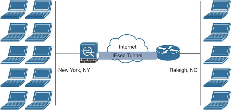
Figure 8-1 Site-to-Site VPN Example
Cisco IPsec VPN solutions have evolved over the years to very robust and comprehensive technologies. Figure 8-2 lists the different Cisco IPsec site-to-site VPN technologies.

Figure 8-2 Site-to-Site VPN Technologies
Figure 8-3 shows an example of a remote-access VPN. In this case, a telecommuter employs an IPsec VPN while a remote user from a hotel employs an SSL VPN to connect to the corporate headquarters.

Figure 8-3 Remote-Access VPN Example
An Overview of IPsec
IPsec uses the Internet Key Exchange (IKE) protocol to negotiate and establish secured site-to-site or remote-access VPN tunnels. IKE is a framework provided by the Internet Security Association and Key Management Protocol (ISAKMP).
IKEv1 Phase 1
Within Phase 1 negotiation, several attributes are exchanged:
Encryption algorithms
Hashing algorithms
Diffie-Hellman groups
Authentication method
Vendor-specific attributes
The following are the traditional encryption algorithms used in IKE:
Data Encryption Standard (DES): 64 bits long (should be avoided in favor of AES)
Triple DES (3DES): 168 bits long (should be avoided in favor of AES)
Advanced Encryption Standard (AES): 128 bits long
AES 192: 192 bits long
AES 256: 256 bits long
Hashing algorithms include the following:
Secure Hash Algorithm (SHA)
Message digest algorithm 5 (MD5)
The common authentication methods in VPNs are pre-shared keys (where peers use a shared secret to authenticate each other) and digital certificates with the use of Public Key Infrastructure (PKI). Typically, small and medium-sized organizations use pre-shared keys as their authentication mechanism. Several large organizations employ digital certificates for scalability, centralized management, and additional security mechanisms.
You can establish a Phase 1 security association (SA) in main mode or aggressive mode. In main mode, the IPsec peers complete a six-packet exchange in three round trips to negotiate the ISAKMP SA, whereas aggressive mode completes the SA negotiation in three packet exchanges. Main mode provides identity protection if pre-shared keys are used. Aggressive mode offers identity protection only if digital certificates are employed.
Figure 8-4 illustrates the six-packet exchange in main mode negotiation.
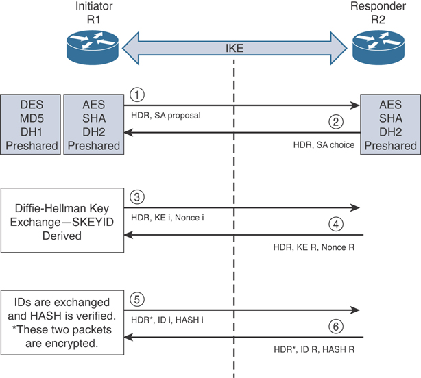
Figure 8-4 IKEv1 Phase 1 Negotiation
In Figure 8-4, two routers are configured to terminate a site-to-site VPN tunnel between them. The router labeled as R1 is the initiator, and R2 is the responder. The following steps are illustrated in Figure 8-3:
R1 (the initiator) has two ISAKMP proposals configured. In the first packet, R1 sends its configured proposals to R2.
R2 evaluates the received proposal. Because it has a proposal that matches the offer of the initiator, R2 sends the accepted proposal back to R1 in the second packet.
Diffie-Hellman exchange and calculation is started. Diffie-Hellman is a key agreement protocol that enables two users or devices to authenticate each other’s pre-shared keys without actually sending the keys over the unsecured medium. R1 sends the Key Exchange (KE) payload and a randomly generated value called a nonce.
R2 receives the information and reverses the equation, using the proposed Diffie-Hellman group/exchange to generate the SKEYID. The SKEYID is a string derived from secret material that is known only to the active participants in the exchange.
R1 sends its identity information. The fifth packet is encrypted with the keying material derived from the SKEYID. The asterisk in Figure 1-8 is used to illustrate that this packet is encrypted.
R2 validates the identity of R1, and R2 sends its own identity information to R1. This packet is also encrypted.
IKEv1 Phase 2
Phase 2 is used to negotiate the IPsec SAs. This phase is also known as quick mode. The ISAKMP SA protects the IPsec SAs because all payloads are encrypted except the ISAKMP header.
A single IPsec SA negotiation always creates two security associations—one inbound and one outbound. Each SA is assigned two unique security parameter index (SPI) values—one by the initiator and the other by the responder.
Another interesting point is that if the VPN router needs to connect multiple networks over the tunnel, it must negotiate twice as many IPsec SAs. Remember, each IPsec SA is unidirectional, so if three local subnets need to go over the VPN tunnel to talk to the remote network, then six IPsec SAs are negotiated. IPsec can use quick mode to negotiate these multiple Phase 2 SAs, using the single pre-established ISAKMP (IKEv1 Phase 1) SA. The number of IPsec SAs can be reduced, however, if source and/or destination networks are summarized.
In addition to generating the keying material, quick mode also negotiates identity information. The Phase 2 identity information specifies which network, protocol, and/or port number to encrypt. Hence, the identities can vary anywhere from an entire network to a single host address, allowing a specific protocol and port.
Figure 8-5 illustrates the Phase 2 negotiation between the two routers that just completed Phase 1.

Figure 8-5 IPsec Phase 2 Negotiation
The following are the steps illustrated in Figure 8-5:
ASA-1 sends the identity information, IPsec SA proposal, nonce payload, and (optional) Key Exchange (KE) payload if Perfect Forward Secrecy (PFS) is used. PFS is employed to provide additional Diffie-Hellman calculations.
ASA-2 evaluates the received proposal against its configured proposal and sends the accepted proposal back to ASA-1, along with its identity information, nonce payload, and the optional KE payload.
ASA-1 evaluates the ASA-2 proposal and sends a confirmation that the IPsec SAs have been successfully negotiated. This starts the data encryption process.
IPsec uses two different protocols to encapsulate the data over a VPN tunnel:
Encapsulation Security Payload (ESP): IP Protocol 50
Authentication Header (AH): IP Protocol 51
ESP is defined in RFC 4303, “IP Encapsulating Security Payload (ESP),” and AH is defined in RFC 4302, “IP Authentication Header.”
IPsec can use two modes with either AH or ESP:
Transport mode: Protects upper-layer protocols, such as User Datagram Protocol (UDP) and TCP
Tunnel mode: Protects the entire IP packet
Transport mode is used to encrypt and authenticate the data packets between the peers. A typical example is the use of GRE over an IPsec tunnel. Tunnel mode is employed to encrypt and authenticate the IP packets when they are originated by the hosts connected behind the VPN device.
Figure 8-6 illustrates the differences between IPsec transport mode versus tunnel mode.

Figure 8-6 IPsec Transport Mode Versus Tunnel Mode
NAT Traversal (NAT-T)
The security protocols (AH and ESP) are Layer 3 protocols and do not have Layer 4 port information. If an IPsec peer is behind a PAT device, the ESP or AH packets are typically dropped. To work around this, many vendors, including Cisco Systems, use a feature called IPsec pass-through. The PAT device that is capable of IPsec pass-through builds the Layer 4 translation table by looking at the SPI values on the packets.
Many industry vendors, including Cisco Systems, implement another feature called NAT Traversal (NAT-T). With NAT-T, the VPN peers dynamically discover whether an address translation device exists between them. If they detect a NAT/PAT device, they use UDP port 4500 to encapsulate the data packets, subsequently allowing the NAT device to successfully translate and forward the packets.
IKEv2
IKE version 2 (IKEv2) is defined in RFC 5996 and enhances the function of performing dynamic key exchange and peer authentication. IKEv2 simplifies the key exchange flows and introduces measures to fix vulnerabilities present in IKEv1. Both IKEv1 and IKEv2 protocols operate in two phases. IKEv2 provides a simpler and more efficient exchange.
Phase 1 in IKEv2 is IKE_SA, consisting of the message pair IKE_SA_INIT. IKE_SA is comparable to IKEv1 Phase 1. The attributes of the IKE_SA phase are defined in the Key Exchange Policy. Phase 2 in IKEv2 is CHILD_SA. The first CHILD_SA is the IKE_AUTH message pair. This phase is comparable to IKEv1 Phase 2. Additional CHILD_SA message pairs can be sent for rekey and informational messages. The CHILD_SA attributes are defined in the data policy.
The following differences exist between IKEv1 and IKEv2:
IKEv1 Phase 1 has two possible exchanges: main mode and aggressive mode. There is a single exchange of a message pair for IKEv2 IKE_SA.
IKEv2 has a simple exchange of two message pairs for the CHILD_SA. IKEv1 uses an exchange of at least three message pairs for Phase 2. In short, IKEv2 has been designed to be more efficient than IKEv1, since fewer packets are exchanged and less bandwidth is needed compared to IKEv1.
IKEv2 supports the use of next-generation encryption protocols and anti-DoS capabilities.
Despite IKEv1 supporting some of the authentication methods used in IKEv2, IKEv1 does not allow the use of Extensible Authentication Protocol (EAP). EAP allows IKEv2 to provide a solution for remote-access VPN, as well.
Figure 8-7 illustrates the attributes negotiated in IKEv1 exchanges in comparison to IKEv2.
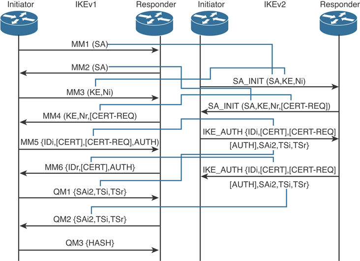
Figure 8-7 Attributes Negotiated in IKEv1 Exchanges in Comparison to IKEv2
Because the message exchanges within IKEv2 are fewer than IKEv1 and cryptographically expensive key material is exchanged in the first two messages (SA_INIT), an attacker could cause a denial-of-service (DoS) condition on an IKEv1-enabled device by sending many SA_INIT requests with a spoofed source address. Subsequently, the gateway would generate key material and dedicate resources to connections that would not be established. The good news is that IKEv2 has the ability to use a stateless cookie. The use of this stateless cookie results in a zero state being assigned to an IKEv2 session if the VPN gateway is under attack.
In IKEv1 implementations, the lifetime of the IKE Phase 1 security association (SA) is negotiated in the first pair of messages (MM1 and MM2). The lifetime configured on the responder must be equal to or less than the lifetime proposed by the initiator in order for Phase 1 to be established. This introduced incompatibilities among different vendors because IKEv1 sessions may not be able to be established if the IKEv1 lifetimes don’t match. In IKEv2, the lifetime is a locally configured value that is not negotiated between peers. This means that a device that is a participant of a VPN tunnel will delete or rekey a session when its local lifetime expires. Each IKEv2 peer can dictate which entity will initiate a rekey. Consequently, the incompatibility issues faced many times in IKEv1 implementations are not present in IKEv2.
IKE also supports three authentication methods: pre-shared keys (PSK), digital signatures, and EAP. IKEv2 clients can authenticate via an already established standardized mechanism, in contrast to IKEv1 (since IKEv1 required non-standard extensions). EAP is a standard that allows the use of a number of different authentication methods to validate the identities of IPsec VPN peers. This is why it is used natively in IKEv2 implementations.
SSL VPNs
SSL-based VPNs leverage the SSL protocol. SSL is a legacy protocol and has been replaced by Transport Layer Security (TLS). However, most of the TLS-based VPNs are still being referred to as “SSL VPNs.” The Internet Engineering Task Force (IETF) created TLS to consolidate the different SSL vendor versions into a common and open standard.
One of the most popular features of SSL VPN is the capability to launch a browser such as Google Chrome, Microsoft Internet Explorer, or Firefox and simply connect to the address of the VPN device, as opposed to running a separate VPN client program to establish an IPsec VPN connection. In most implementations, a clientless solution is possible. Users can access corporate intranet sites, portals, and email from almost anywhere (even from an airport kiosk). Because most people allow SSL (TCP port 443) over their firewalls, it is unnecessary to open additional ports.
The most successful application running on top of SSL is HTTP because of the huge popularity of the World Wide Web. All the most popular web browsers in use today support HTTPS (HTTP over SSL/TLS). This ubiquity, if used in remote-access VPNs, provides some appealing properties:
Secure communication using cryptographic algorithms: HTTPS/TLS offers confidentiality, integrity, and authentication.
Ubiquity: The ubiquity of SSL/TLS makes it possible for VPN users to remotely access corporate resources from anywhere, using any PC, without having to preinstall a remote-access VPN client.
Low management cost: The clientless access makes this type of remote-access VPN free of deployment costs and free of maintenance problems at the end-user side. This is a huge benefit for the IT management personnel, who would otherwise spend considerable resources to deploy and maintain their remote-access VPN solutions.
Effective operation with a firewall and NAT: SSL VPN operates on the same port as HTTPS (TCP/443). Most Internet firewalls, proxy servers, and NAT devices have been configured to correctly handle TCP/443 traffic. Consequently, there is no need for any special consideration to transport SSL VPN traffic over the networks. This has been viewed as a significant advantage over native IPsec VPN, which operates over IP protocol 50 (ESP) or 51 (AH), which in many cases needs special configuration on the firewall or NAT devices to let traffic pass through.
As SSL VPN evolves to fulfill another important requirement of remote-access VPNs—namely, the requirement of supporting any application—some of these properties are no longer applicable, depending on which SSL VPN technology the VPN users choose. But overall, these properties are the main drivers for the popularity of SSL VPN in recent years and are heavily marketed by SSL VPN vendors as the main reasons for IPsec replacement.
Today’s SSL VPN technology uses TLS as secure transport and employs a heterogeneous collection of remote-access technologies such as reverse proxy, tunneling, and terminal services to provide users with different types of access methods that fit different environments.
HTTPS provides secure web communication between a browser and a web server that supports the HTTPS protocol. SSL VPN extends this model to allow VPN users to access corporate internal web applications and other corporate application servers that might or might not support HTTPS, or even HTTP. SSL VPN does this by using several techniques that are collectively called reverse proxy technology.
A reverse proxy is a proxy server that resides in front of the application servers, normally web servers, and functions as an entry point for Internet users who want to access the corporate internal web application resources. To the external clients, a reverse proxy server appears to be the true web server. Upon receiving the user’s web request, a reverse proxy relays the user request to the internal web server to fetch the content on behalf of the user and relays the web content to the user with or without additional modifications to the data being presented to the user.
Many web server implementations support reverse proxy. One example is the mod_proxy module in Apache. With so many implementations, you might wonder why you need an SSL VPN solution to have this functionality. The answer is that SSL VPN offers much more functionality than traditional reverse proxy technologies:
SSL VPN can transform complicated web and some non-web applications that simple reverse proxy servers cannot handle. The content transformation process is sometimes called “webification.” For example, SSL VPN solutions enable users to access Windows or UNIX file systems. The SSL VPN gateway must be able to communicate with internal Windows or UNIX servers and webify the file access in a web browser–presentable format for the VPN users.
SSL VPN supports a wide range of business applications. For applications that cannot be webified, SSL VPN can use other resource access methods to support them. For users who demand ultimate access, SSL VPN provides network-layer access to directly connect a remote system to the corporate network, in the same manner as an IPsec VPN.
SSL VPN provides a true remote-access VPN package, including user authentication, resource access privilege management, logging and accounting, endpoint security, and user experience.
The reverse proxy mode in SSL VPN is also known as clientless web access or clientless access because it does not require any client-side applications to be installed on the client machine. Client-based SSL VPN provides a solution where you can connect to the corporate network by just pointing your web browser to the Cisco ASA without the need of additional software being installed in your system.
Cisco AnyConnect Secure Mobility
There is a new wave of technological adoption and security threats—mobile devices that allow employees to work from anywhere at any time. Mobility is not completely new for enterprises. As discussed earlier in this chapter, remote-access and telecommuting solutions have existed for quite some time. However, the rapid proliferation of mobile devices increases on a daily basis. Every organization must embrace mobility to remain competitive and evolve to a new model of efficient workloads, especially because many organizations have spent millions of dollars enabling remote-access VPNs to their networks. In some environments, smartphones, tablets, and other mobile devices have surpassed traditional PC-based devices.
The Cisco AnyConnect Secure Mobility solution is designed to secure connections from these mobile devices. The combination of the Cisco AnyConnect Secure Mobility Client, the Cisco ASA, Cisco ISE, Cisco AMP, Cisco Umbrella, and Cisco content security appliances provides a complete, secure mobility solution.
The Cisco AnyConnect Secure Mobility Client is built on SSL VPN technology that enables security to the network behind the Cisco ASA and also provides corporate policy enablement when users are not connected to the corporate Cisco ASA.
Figure 8-8 shows the Cisco AnyConnect Secure Mobility Client.
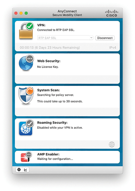
Figure 8-8 The Cisco AnyConnect Secure Mobility Client
Deploying and Configuring Site-to-Site VPNs in Cisco Routers
As you recall from Figure 8-2, many technologies have been used for site-to-site VPN and have evolved through the years—from static traditional crypto maps (traditional site-to-site VPNs in Cisco IOS and Cisco IOS-XE devices) to DMVPN, GETVPN, and FlexVPN. The sections that follow discuss all of these technologies in more detail.
Traditional Site-to-Site VPNs in Cisco IOS and Cisco IOS-XE Devices
Some people refer to the traditional (original) configuration of site-to-site VPNs in Cisco IOS and Cisco IOS-XE devices as “crypto maps.” However, a crypto map is a Cisco IOS and/or Cisco IOS-XE software configuration command that performs a number of functions related to setting up an IPsec SA. When you configure a crypto map, the networks you want to be protected by the IPsec tunnel are referenced with access control lists. The IPsec Phase 2 security policy, protocol, mode, and algorithms are defined by a transform set (these settings include to whom the session will be established and is defined by the peer statement). Crypto maps are applied to an interface. A crypto map can be applied on a physical or tunnel interface (with certain restrictions).
So, let’s take a look at how this all is configured in Cisco routers. Let’s assume that you were hired by SecretCorp to establish a site-to-site VPN tunnel between two routers (R1 in London and R2 in Raleigh, North Carolina). The topology shown in Figure 8-9 is used to illustrate this scenario. The goal is for the devices in 10.1.1.0/24 be able to communicate to the devices in 192.168.1.0/24.

Figure 8-9 Site-to-Site IPsec VPN Configuration Topology
Example 8-1 shows R1’s configuration. The highlighted comments explain each section of the configuration. In this example, IKEv1 and crypto maps are used.
Example 8-1 R1’s Configuration
!--- Create an ISAKMP policy for IKEv1 Phase 1
crypto isakmp policy 10
 hash sha
 authentication pre-share
!--- Define the pre-shared key and the remote peer address
crypto isakmp key superSecretKey! address 10.2.2.1
!
!--- Create the Phase 2 policy in a transform-set.
!--- The transform set is configured with AES-256 and SHA-HMAC.
crypto ipsec transform-set myset esp-aes 256 esp-sha-hmac
!
!--- Create the crypto map and define the peer IP address, transform
!--- set, and an access control list (ACL) for the tunnel.
crypto map mymap 10 ipsec-isakmp
 set peer 10.2.2.1
 set transform-set myset
 match address 100
!
interface GigabitEthernet0/0
 ip address 10.1.1.0 255.255.255.0
!
!--- Apply the crypto map on the "outside" interface.
interface GigabitEthernet0/1
 ip address 10.1.2.1 255.255.255.0
 crypto map mymap
!
!--- Add a route for the default gateway (10.1.2.2)
ip route 0.0.0.0 0.0.0.0 10.1.2.2
!
!--- Create an ACL for the traffic to be encrypted over the tunnel.
access-list 100 permit ip 10.1.1.0 0.0.0.255 192.168.1.0 0.0.0.255
!
Example 8-2 shows R2’s configuration.
Example 8-2 R2’s configuration
!--- Create an ISAKMP policy for IKEv1 Phase 1
crypto isakmp policy 10
 hash sha
 authentication pre-share
!--- Define the pre-shared key and the remote peer address
crypto isakmp key superSecretKey! address 10.1.2.1
!
!--- Create the Phase 2 policy in a transform-set.
!--- The transform set is configured with AES-256 and SHA-HMAC.
crypto ipsec transform-set myset esp-aes 256 esp-sha-hmac
!
!--- Create the crypto map and define the peer IP address, transform
!--- set, and an access control list (ACL) for the tunnel.
crypto map mymap 10 ipsec-isakmp
 set peer 10.1.2.1
 set transform-set myset
 match address 100
!
interface GigabitEthernet0/0
 ip address 192.168.1.0 255.255.255.0
!
!--- Apply the crypto map on the "outside" interface.
interface GigabitEthernet0/1
 ip address 10.2.2.1 255.255.255.0
 crypto map mymap
!
!--- Add a route for the default gateway (10.2.2.2)
ip route 0.0.0.0 0.0.0.0 10.2.2.2
!
access-list 100 permit ip 192.168.1.0 0.0.0.255 10.1.1.0 0.0.0.255!
Tunnel Interfaces
Cisco IOS also has an alternative to crypto maps: tunnel interfaces with tunnel protection. This is accomplished by creating a logical interface that represents the source and destination endpoints of the tunnel. The tunnel interface connects the transport network and the overlay network (the traffic that will transverse within the tunnel). Cisco IOS and Cisco IOS-XE tunnel interfaces support different types of encapsulation (or modes):
Generic Routing Encapsulation (GRE) protocol
IP-in-IP
Distance Vector Multicast Routing Protocol (DVMRP)
IPv6-in-IPv4
The most common type of encapsulation used with these IPsec implementations is GRE over IPsec.
Generic Routing Encapsulation (GRE) over IPsec is covered next, as well as the reasons why this is needed when using non-IP protocols or multicast.
GRE over IPsec
GRE (protocol 47) is defined by RFC 2784 and extended by RFC 2890. GRE provides a simple mechanism to encapsulate packets of any protocol (the payload packets) over any other protocol (the delivery protocol) between two endpoints. In a GRE tunnel implementation, the GRE protocol adds its own header (4 bytes plus options) between the payload (data) and the delivery header.
The following is the overhead of a GRE packet compared to the original packet:
4 bytes (+ GRE options) for the GRE header,
20 bytes (+ IP options) for the outer IPv4 header (GRE over IPv4), or
40 bytes (+ extension headers) for the outer IPv6 header (GRE over IPv6).
In GRE over IPsec, the original packets are first encapsulated within GRE, which results in a new IP packet being created inside the network infrastructure device. This GRE packet is then selected for encryption and encapsulated into IPsec, as shown in Figure 8-10.

Figure 8-10 Site-to-site IPsec VPN Configuration Topology
The actual encapsulation depends on whether tunnel or transport mode is used. Figure 8-10 shows a representation of GRE over IPsec in tunnel mode. When you deploy GRE over IPsec in tunnel mode, the plaintext IPv4 or IPv6 packet is encapsulated into GRE. Then that packet is encapsulated into another IPv4 or IPv6 packet containing the tunnel source and destination IP addresses. This is protected by IPsec for confidentiality and/or integrity assurance, with finally an additional outer IP header being used as the tunnel source and tunnel destination to route the traffic to the destination.
In contrast, with GRE over IPsec transport mode, a plaintext IPv4 or IPv6 packet is GRE-encapsulated and then protected by IPsec for confidentiality and/or integrity protection; the outer IP header with the GRE tunnel source and destination addresses helps route the packet correctly.
The following is the IPsec tunnel mode overhead compared to the original packet:
40 bytes (more if IP options are present) for the outer and inner IPv4 headers, or
80 bytes (more if extension headers are present) for the outer and inner IPv6 headers, plus the GRE (4 byte) and encryption overhead.
Traditional GRE over IPsec configuration is pretty straightforward. Let’s use the same topology shown in Figure 8-9 and configure a GRE over IPsec tunnel between R1 and R2. Traditional GRE is configured with Tunnel interfaces. Example 8-3 shows the Tunnel interface configuration of R1.
Example 8-3 R1’s GRE Tunnel Interface Configuration
interface Tunnel0
 ip address 192.168.16.2 255.255.255.0
 tunnel source GigabitEthernet0/1
 tunnel destination 10.2.2.1
 crypto map mymap
In traditional GRE over IPsec configurations, the crypto map is applied to the Tunnel interface, as demonstrated in Example 8-3. R2’s configuration will mimic and reciprocate R1’s configuration.
One of the main use cases for GRE over IPsec is to be able to carry routing protocol information (that is, multicast packets in the case of OSPF) over the VPN tunnel. Additional technologies and standards have been developed for this purpose, as well. The following are examples of such standards and technologies:
Multicast Group Security Architecture (RFC 3740)
Group Domain of Interpretation (RFC 6407)
Cisco’s GETVPN (covered later in this chapter)
More About Tunnel Interfaces
As you know by now, the original implementation of IPsec VPNs used on Cisco IOS was known as crypto maps. The concept of configuring a crypto map was closely aligned to the IPsec protocol, with traffic that was required to be encrypted being defined in an access control list. This list was then referenced within an entry in the crypto map along with the IPsec cryptographic algorithms within the transform set. This configuration could become overly complex, and administrators introduced many errors when long access control lists were used.
Cisco introduced the concept of logical tunnel interfaces. These logical interfaces are basically doing the same as traditional crypto maps but they are user configurable. The attributes used by this logical tunnel interface are referenced from the user-configured IPsec profile used to protect the tunnel. All traffic traversing this logical interface is protected by IPsec. This technique allows for traffic routing to be used to send traffic with the logical tunnel being the next hop and results in simplified configurations with greater flexibility for deployments. When the requirement for a user to configure what traffic was to be protected is removed, it reduces the chances of misconfigurations, which frequently occurred with manual configurations of access control lists with crypto maps.
On Cisco routers, every access control entry (ACE) in an access control list (ACL) consumes a ternary content-addressable memory (TCAM) entry. TCAM has a limited number of entries. Consequently, crypto map implementations that contain a large number of access control entries and the device TCAM can become exhausted. Tunnel protection uses only a single TCAM entry and allows for a larger number of IPsec security associations to be established compared to using crypto maps.
The tunnel mode command was introduced to simplify IPsec and GRE configurations. The difference between the two tunnel interface types is the sequence of encapsulation. In short, VTI (tunnel mode ipsec {ipv4 | ipv6}) carries IPv4 or IPv6 traffic directly within IPsec tunnel mode, while GRE over IPsec (tunnel mode gre {ip | ipv6}) first encapsulates traffic within GRE and a new IP header before encapsulating the resulting GRE over IP packet within IPsec transport mode.
You can use static virtual interfaces (IPsec or GRE over IPsec) on routers configured as initiators and responders. Example 8-4 includes a static Tunnel interface configuration.
Example 8-4 A Static Tunnel Interface Configuration (IPsec Mode)
interface Tunnel0
 ip address 192.168.16.2 255.255.255.0
 tunnel source GigabitEthernet0/0
 tunnel mode ipsec ipv4
 tunnel destination 209.165.200.225
 tunnel protection ipsec profile default
You can also use dynamic tunnel interfaces. When you configure dynamic interfaces (IPsec tunnel or GRE over IPsec), the tunnel interface is in a responder-only mode. In the case of IKEv2 implementations, the tunnel negotiation triggers the cloning of a virtual template into a virtual-access interface (interface Virtual-Access number) that represents the point-to-point link to the remote peer that is protected by IPsec.
Example 8-5 shows a sample virtual template (dynamic VTI) configuration.
Example 8-5 A Dynamic Virtual-Template Configuration
interface Loopback1
 ip address 10.3.3.3 255.255.255.255

interface Virtual-Template1 type tunnel
 ip unnumbered Loopback1
 tunnel mode ipsec ipv4
 tunnel protection ipsec profile default
Multipoint GRE (mGRE) Tunnels
A particular type of GRE encapsulation is multipoint GRE (mGRE). mGRE interfaces are configured with the tunnel mode gre multipoint command. A single static GRE tunnel interface is used as the endpoint for multiple site-to-site tunnels. DMVPN is based on this mode and uses a single interface on each hub as well as on each spoke to terminate all static and dynamic tunnels. FlexVPN does not rely on multipoint interfaces.
An mGRE interface is basically a GRE tunnel interface that acts as if it is directly connected to a group of remote mGRE interfaces. DMVPN uses mGRE and the Next Hop Resolution Protocol (NHRP), acting as a resolution mechanism between a peer’s tunnel address (the IP address configured on the peer’s mGRE interface) and the mGRE endpoint address on that peer, called the Non-Broadcast Multiple Access (NBMA) address.
DMVPN
DMVPN is a technology created by Cisco that aims to reduce the hub router configuration. In legacy hub-and-spoke IPsec configuration, each spoke router has a separate block of configuration lines on the hub router that define the crypto map characteristics, the crypto ACLs, and the GRE tunnel interface. When deploying DMVPN, you configure a single mGRE tunnel interface, a single IPsec profile, and no crypto access lists on the hub router. The main benefit is that the size of the configuration on the hub router remains the same even if spoke routers are added at a later point.
DMVPN groups many spokes into a single mGRE interface. This allows you to not have to configure a distinct physical or logical interface for each spoke.
DMVPN also uses Next Hop Resolution Protocol (NHRP), which is a client and server protocol (the hub is the server and the spokes are the clients). The hub (or server) maintains an NHRP database of the public interface addresses of the each spoke. Each spoke registers its real address when it boots and queries the NHRP database for real addresses of the destination spokes to build direct tunnels.
DMVPN also eliminates the need for spoke-to-spoke configuration for direct tunnels. When a spoke router tries to transmit a packet to another spoke router, it uses NHRP to dynamically determine the required destination address of the target spoke router. Then the two spoke routers dynamically create an IPsec tunnel between them so data can be directly transferred. This is illustrated in Figure 8-11.
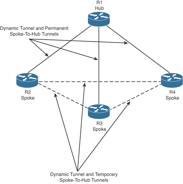
Figure 8-11 DMVPN Example
In Figure 8-11, each spoke (R2, R3, and R4) has a permanent IPsec tunnel to the hub (R1), not to the other spokes within the network. Each spoke registers as clients of R1 (the NHRP server). If a spoke wants to send traffic to another spoke, it queries the NHRP server (R1), and after the originating spoke “learns” the peer address of the target spoke, it initiates a dynamic IPsec tunnel to the target spoke.
Example 8-6 shows an example of a hub configuration for DMVPN.
Example 8-6 A Hub Configuration for DMVPN
!The ISAKMP policy
crypto isakmp policy 1
 encryption aes
 authentication pre-share
 group 14
! A dynamic ISAKMP key and IPsec profile
crypto isakmp key supersecretkey address 0.0.0.0
crypto ipsec transform-set trans2 esp-aes esp-sha-hmac
mode transport
!
crypto ipsec profile my_hub_vpn_profile
 set transform-set trans2
!
! The tunnel interface with NHRP
Interface Tunnel0
 ip address 10.0.0.1 255.255.255.0
 ip nhrp authentication anothersupersecretkey
 ip nhrp map multicast dynamic
 ip nhrp network-id 99
 ip nhrp holdtime 300
 tunnel source GigabitEthernet0/0
 tunnel mode gre multipoint
! This line must match on all nodes that want to use this mGRE tunnel.
 tunnel key 100000
 tunnel protection ipsec profile my_hub_vpn_profile
!
interface GigabitEthernet0/0
 ip address 172.16.0.1 255.255.255.0
!
interface GigabitEthernet0/1
 ip address 192.168.0.1 255.255.255.0
!
router eigrp 1
 network 10.0.0.0 0.0.0.255
 network 192.168.0.0 0.0.0.25
Example 8-7 shows an example of a spoke configuration in a DMVPN deployment.
Example 8-7 A Spoke Configuration Example in a DMVPN Deployment
crypto isakmp policy 1
 encr aes
 authentication pre-share
 group 14
crypto isakmp key supersecretkey address 0.0.0.0
!
crypto ipsec transform-set trans2 esp-aes esp-sha-hmac
 mode transport
!
crypto ipsec profile my_spoke_vpn_profile
 set transform-set trans2
!
interface Tunnel0
 ip address 10.0.0.2 255.255.255.0
 ip nhrp authentication anothersupersecretkey
 ip nhrp map 10.0.0.1 172.17.0.1
 ip nhrp map multicast 172.17.0.1
 ip nhrp network-id 99
 ip nhrp holdtime 300
! Configures the hub router as the NHRP next-hop server.
 ip nhrp nhs 10.0.0.1
  tunnel source GigabitEthernet0/0
 tunnel mode gre multipoint
 tunnel key 100000
 tunnel protection ipsec profile my_spoke_vpn_profile
!
interface GigabitEthernet0/0
 ip address dhcp hostname Spoke1
!
interface GigabitEthernet0/1
 ip address 192.168.1.1 255.255.255.0
!
router eigrp 1
 network 10.0.0.0 0.0.0.255
 network 192.168.1.0 0.0.0.255
GETVPN
Cisco’s Group Encrypted Transport VPN (GETVPN) provides a collection of features and capabilities to protect IP multicast group traffic or unicast traffic over a private WAN. GETVPN combines the keying protocol Group Domain of Interpretation (GDOI) and IPsec. GETVPN enables the router to apply encryption to “native” (non-tunneled) IP multicast and unicast packets and removes the requirement to configure tunnels to protect multicast and unicast traffic. GETVPN allows Multiprotocol Label Switching (MPLS) networks to maintain full-mesh connectivity, natural routing path, and Quality of Service (QoS).
GETVPN incorporates Multicast Rekeying. Multicast Rekeying and GETVPN are based on GDOI, as defined in RFC 3547. GDOI is defined as the ISAKMP Domain of Interpretation (DOI) for group key management. The GDOI protocol operates between a group member and a group controller or key server (GCKS), which establishes SAs among authorized group members.
In addition to the existing IKE, IPsec, and multicast technologies, a GETVPN solution relies on the following core building blocks to provide the required functionality:
GDOI (RFC 6407)
Key servers (KSs)
Cooperative (COOP) KSs
Group members (GMs)
IP tunnel header preservation
Group security association
Rekey mechanism
Time-based anti-replay (TBAR)
G-IKEv2
IP-D3P
Figure 8-12 shows a sample topology of a GETVPN implementation.

Figure 8-12 GETVPN Example
In the example illustrated in Figure 8-12, the group members are customer edge (CE) routers connected to provider edge (PE) routers. The group members register with the key server to get the SAs that are necessary to communicate with the group. The group member sends the group ID to the key server to get the respective policy and keys for this group. These keys are refreshed periodically, and before the current IPsec SAs expire, so that there is no loss of traffic.
The key server creates and maintains the keys for the group. During the registration process of a new group member participant, the key server downloads this policy and the keys to the group member. The key server is also in charge of rekeying before existing keys expire. In short, the key server has two major roles: servicing registration requests and sending rekeys.
GETVPN group members can register at any time. When they register the new group member, it receives the most current policy and keys. The key server verifies the group ID that the group member is attempting to join. If this ID is a valid group ID, the key server sends the SA policy to the group member. After the group member acknowledges that it can handle the downloaded policy, the key server downloads the respective keys.
Figure 8-13 includes details about the two types of keys that group members can retrieve from the key server.
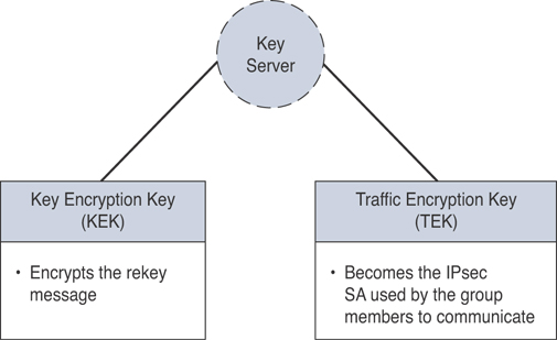
Figure 8-13 GETVPN Keys
The key server will send rekey messages if an impending IPsec SA expiration occurs or if the policy has changed on the key server. The rekey messages could also be retransmitted intermittently to account for possible packet loss (if the rekey messages fail for some reason).
The following are the minimum requirements of a basic GETVPN key server configuration:
IKE policy
RSA key for re-keying (used to secure the re-key messages)
IPsec Phase 2 polices
Traffic classification ACL (to specify which traffic should be encrypted)
The following are the minimum requirements of a basic GETVPN group member configuration:
IKE policy
GDOI crypto map
Crypto map applied to an interface
FlexVPN
As you learned earlier in this chapter, FlexVPN is an IKEv2-based solution that provides several benefits beyond traditional site-to-site VPN implementations. The following are some of the benefits of FlexVPN deployments:
Standards-based solution that can interoperate with non-Cisco IKEv2 implementations.
Supports different VPN topologies, including point-to-point, remote-access, hub-and-spoke, and dynamic mesh (including per-user or per-peer policies).
Combines all these different VPN technologies using one command-line interface (CLI) set of configurations. FlexVPN supports unified configuration and show commands, the underlying interface infrastructure, and features across different VPN topologies.
Support for dynamic overlay routing.
Integration with Cisco IOS Authentication, Authorization, and Accounting (AAA) infrastructure.
Supports GRE and native IPsec encapsulations by automatically detecting the encapsulation protocol.
Supports IPv4 and IPv6 overlay and underlay by automatically detecting the IP transport type.
Figure 8-14 illustrates the FlexVPN IKE authentication and configuration generation process between a FlexVPN client (IKEv2 initiator) and the FlexVPN server.

Figure 8-14 FlexVPN IKE Authentication and Configuration Generation Process
FlexVPN implementations support EAP only as a remote authentication method (leveraging an external EAP server). The FlexVPN server does not support EAP as a local authentication method and acts a pass-through authenticator relaying EAP messages between an EAP server and the IKEv2 clients (otherwise known as EAP supplicants or peers). The FlexVPN server authenticates the client or supplicant using a digital certificate-based authentication method. This authentication process is illustrated in Figure 8-15.
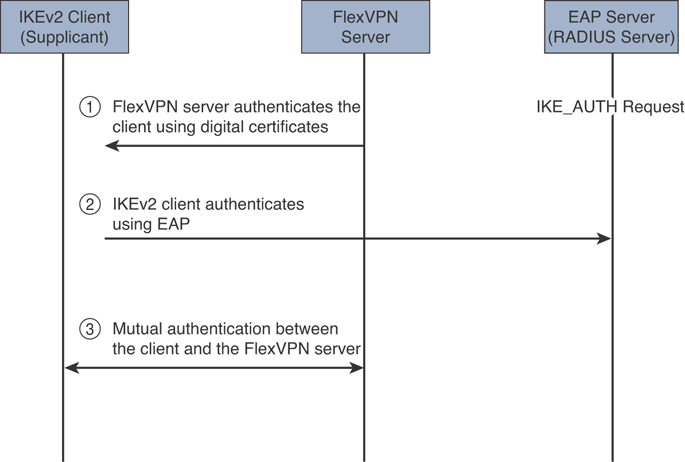
Figure 8-15 FlexVPN High-Level IKEv2 and EAP Authentication Process
The EAP messages between the IKEv2 client and the FlexVPN server are embedded within the IKEv2 EAP payload and are transported within the IKE_AUTH request and response messages. The EAP messages between the FlexVPN server and the RADIUS-based EAP server are embedded within the RADIUS EAP-Message attribute. Several other things happen during the second step illustrated in Figure 8-15. The EAP server (RADIUS server) uses an EAP-Request message to request information from the IKEv2 client (EAP supplicant), and the IKEv2 client uses an EAP-Response message to provide the requested information. Subsequently, the RADIUS/EAP server uses EAP-Success or EAP-Failure messages to communicate the authentication result.
EAP is configured in the IKEv2 profile. In order to configure EAP as a remote authentication method, the local authentication method must be certificate-based. You can define the AAA authentication method list to specify the RADIUS server hosting the EAP server, as demonstrated in Example 8-8.
Example 8-8 Defining the AAA Parameters on the FlexVPN Server
aaa new-model
aaa authentication login my_radius_list group my_radius_group
aaa group server radius my_radius_group
 server name radius_server
Example 8-9 shows how to define the RADIUS server. The RADIUS server has the IP address 10.1.2.3. UDP port 1645 is used for RADIUS authentication, and UDP port 1646 is used for RADIUS accounting.
Example 8-9 Defining the RADIUS Server
radius server radius_server
 address ipv4 10.1.2.3 auth-port 1645 acct-port 1646
 key radius_key
Example 8-10 shows the EAP configuration in the FlexVPN server (remote authentication method with the authentication remote eap command). This configuration assumes that you have AAA enabled using a RADIUS-based external EAP server.
Example 8-10 FlexVPN Server EAP Configuration
crypto ikev2 profile ikev2_profile
 aaa authentication eap my_radius_list
 authentication remote eap query-identity
 authentication remote eap timeout 120
 authentication remote rsa-sig
 aaa authentication eap my_radius_list
Let’s take a look at the FlexVPN deployment example illustrated in Figure 8-16. R1 is configured as a FlexVPN server, and R2 is configured as a FlexVPN client. The server interacts with the RADIUS server (10.1.2.3) for authentication. This is a scalable management of per-peer pre-shared keys using a RADIUS server (AAA-based pre-shared keys).

Figure 8-16 FlexVPN Configuration Example Topology
Example 8-11 shows the configuration of the FlexVPN server (R1). The highlighted lines explain each configuration section.
Example 8-11 FlexVPN Server’s (R1) Configuration
! AAA configuration. R1 is configured with AAA authorization to use
! the RADIUS server (10.1.2.3) to retrieve the IKEv2 pre-shared keys.

aaa new-model
aaa group server radius radius_group1
 server name radius_server1
!
aaa authorization network aaa_psk_list group radius_group1
!
radius server radius_server1
 address ipv4 10.1.2.3 auth-port 1645 acct-port 1646
 key radius_server1_key
! The IKEv2 name mangler is configured to derive the AAA username from
! the hostname portion of the peer IKEv2 identity of type FQDN.
! When each branch router is configured with a unique local FQDN identity,
! the name mangler will yield a unique AAA username for the pre-shared key
! lookup on the RADIUS server.
! The IKEv2 profile is configured to match all the branch routers, based on
! the domain portion (secretcorp.org) of the peer FQDN identity.
! The profile is configured to use an AAA-based keyring that would retrieve
! the pre-shared keys, using AAA authorization from the RADIUS
! server specified in the referenced AAA method list.
! The referenced IKEv2 name mangler will yield a unique AAA username for
! pre-shared key lookup on the RADIUS server that is derived from the
! username portion the peer FQDN identity.
crypto ikev2 name-mangler aaa_psk_name_mangler
 fqdn hostname
!
crypto ikev2 profile default
 match identity remote fqdn domain example.com
 identity local fqdn hq.example.com
 authentication local pre-share
 authentication remote pre-share
 keyring aaa aaa_psk_list name-mangler aaa_psk_name_mangler
Example 8-12 shows the FlexVPN client’s (R2) configuration. R2 is configured with a unique local IKEv2 identity and a local IKEv2 keyring with a symmetric pre-shared key for authentication with the hub router at headquarters.
Example 8-12 FlexVPN Client’s (R2) Configuration
crypto ikev2 keyring local_keyring
peer hub-router
 address 10.1.1.1
 pre-shared-key branch1-hub-key

crypto ikev2 profile default
match identity remote fqdn hq.secretcorp.org
identity local fqdn rtp-branch.secretcorp.org
authentication local pre-share
authentication remote pre-share
keyring local local_keyring
Debug and Show Commands to Verify and Troubleshoot IPsec Tunnels
When you configure IPsec VPNs in supported Cisco devices, you can use a plethora of debug and show commands for IP connectivity, IKEv1, IKEv2, IPsec, GRE encapsulation, RADIUS authentication, and many other related technologies. Furthermore, these technologies are fairly complex and often are made up of a number of components themselves.
Figure 8-17 shows different methods to obtain valuable information from a Cisco infrastructure device for troubleshooting.
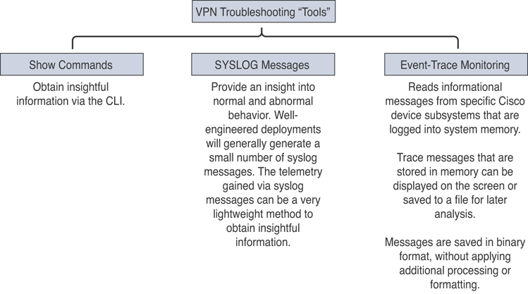
Figure 8-17 Different Methods to Obtain Valuable Information for IPsec Troubleshooting
Figure 8-18 shows the different IPsec VPN’s functions, protocols, and related troubleshooting commands.
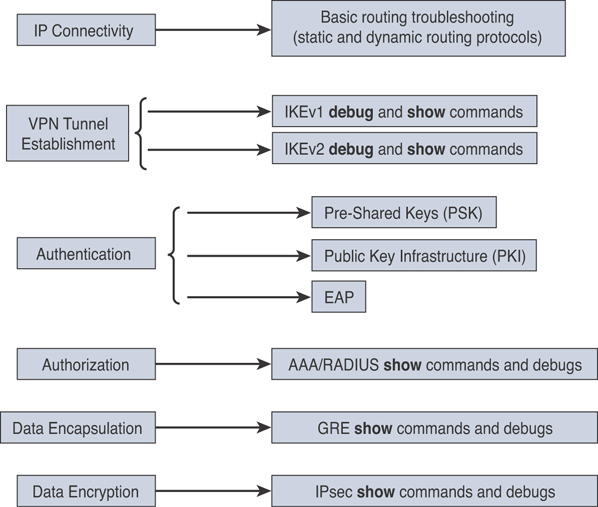
Figure 8-18 IPsec VPN Functions, Protocols, and Related Troubleshooting Commands
Let’s start by going over some of the most popular show commands for troubleshooting IPsec VPNs in Cisco routers. In legacy VPN implementations, you can use the show crypto isakmp sa command to troubleshoot and display information about the security associations (SAs) built between the IPsec peers. Example 8-13 shows the output of the show crypto isakmp sa command for a connection between 10.1.1.1 and 10.2.2.2.
Example 8-13 The Output of the show crypto isakmp sa Command
R2# show crypto isakmp sa
dst       src        state     conn-id     slot
10.1.1.1  10.2.2.2   QM_IDLE    1          0
In newer IKEv2 implementations, you can display the IKE SAs with the show crypto ikev2 sa command, as shown in Example 8-14.
Example 8-14 Displaying the IKE SAs with the show crypto ikev2 sa Command
R1# show crypto ikev2 sa
Tunnel-id   Local          Remote           fvrf/ivrf          Status
2           10.1.1.1/500   10.2.2.2/500     (none)/(none)      READY
      Encr: 3DES, Hash: SHA96, DH Grp:2, Auth: PSK
      Life/Active Time: 86400/361 sec
You can also display more detailed information about the IKEv2 SAs with the show crypto ikev2 sa detailed command, as demonstrated in Example 8-15.
Example 8-15 The Output of the show crypto ikev2 sa detailed Command
R1# show crypto ikev2 sa detailed
Tunnel-id   Local          Remote           fvrf/ivrf          Status
2           10.1.1.1/500    10.2.2.2/500      (none)/(none)      READY
      Encr: 3DES, Hash: SHA96, DH Grp:2, Auth: PSK
      Life/Active Time: 86400/479 sec
      CE id: 0, Session-id: 2, MIB-id: 2
      Status Description: Negotiation done
      Local spi: ACF1453548BE731C
      Remote spi: 45CB158F05817B3A
      Local id:      10.1.1.1           Remote id:     10.2.2.2
      Local req mess id:    3           Remote req mess id: 0
      Local next mess id:    3          Remote next mess id: 1
      Local req queued:    3            Remote req queued: 0
      Local window:    5                Remote window: 5
      DPD configured for 0 seconds
      NAT-T is not detected
      Redirected From: 10.1.1.88
To display information about the active IKEv2 sessions, use the show crypto ikev2 session command, as shown in Example 8-16.
Example 8-16 Output of the show crypto ikev2 session Command
R1# show crypto ikev2 session
Session-id:1, Status:UP-ACTIVE, IKE count:1, CHILD count:1
Tunnel-id   Local           Remote           fvrf/ivrf          Status
1           10.1.1.1/500    10.2.2.2/500     (none)/(none)      READY
      Encr: 3DES, Hash: SHA96, DH Grp:2, Auth: PSK
      Life/Active Time: 86400/65 sec
Child sa: local selector  10.0.0.1/0 - 10.0.0.1/65535
          remote selector 10.0.0.2/0 - 10.0.0.2/65535
          ESP spi in/out: 0x9430B91/0x6C060041
          CPI in/out: 0x9FA4/0xC669
The following are some additional show commands to display IKEv2 statistics:
show crypto ikev2 stats
show crypto ikev2 stats exchange
show crypto ikev2 stats ext-service
show crypto ikev2 stats priority-queue
show crypto ikev2 stats timeout
You can also use numerous debug commands to troubleshoot IPsec implementations, such as the following:
debug crypto isakmp (for legacy IKE implementations)
debug crypto ikev2 (for IKEv2 implementations)
debug crypto ikev2 internal
debug radius authentication (useful to troubleshoot authentication communication between the router and the RADIUS server)
debug crypto ipsec
Example 8-17 includes the output of the debug crypto ikev2, debug crypto ikev2 internal, and debug radius authentication commands during a FlexVPN tunnel establishment between R1 and R2.
Example 8-17 Troubleshooting a FlexVPN Deployment Using debug crypto ikev2, debug crypto ikev2 internal, and debug radius authentication
IKEv2:(SESSION ID = 69,SA ID = 1):Received Packet [From 10.1.1.1:59040/To
10.2.2.2:500/VRF i0:f0]
Initiator SPI : 3A1C6331D3A4726E - Responder SPI : 123A08C78505C625 Message id: 1
IKEv2 IKE_AUTH Exchange REQUEST
Payload contents:
IKEv2-INTERNAL:Parse Vendor Specific Payload: (CUSTOM) VID IDi CERTREQ CFG SA
IKEv2:(SESSION ID = 69,SA ID = 1):Generating EAP request
IKEv2:(SESSION ID = 69,SA ID = 1):Building packet for encryption.
Payload contents:
 VID IDr CERT CERT AUTH EAP
IKEv2:(SESSION ID = 69,SA ID = 1):Sending Packet [To 10.1.1.1:59040/From
10.2.2.2:4500/VRF i0:f0]
Initiator SPI : 3A1C6331D3A4726E - Responder SPI : 123A08C78505C625 Message id: 1
IKEv2 IKE_AUTH Exchange RESPONSE
IKEv2:(SESSION ID = 69,SA ID = 1):Received Packet [From 10.1.1.1:59040/To
10.2.2.2:4500/VRF i0:f0]
Initiator SPI : 3A1C6331D3A4726E - Responder SPI : 123A08C78505C625 Message id: 2
IKEv2 IKE_AUTH Exchange REQUEST

Payload contents:
 EAP

IKEv2:(SESSION ID = 69,SA ID = 1):Processing EAP response
IKEv2:Use authen method list TEST
IKEv2:pre-AAA: client sent User1 as EAP-Id response
IKEv2:sending User1 [EAP-Id] as username to AAA
IKEv2:(SA ID = 1):[IKEv2 -> AAA] Authentication request sent
RADIUS(00000049): Send Access-Request to 10.1.2.3:1812 id 1645/36, len 196
RADIUS:  authenticator 5A 04 CC CF DA 86 4C D3 - 4E B8 8A F3 75 47 52 81
RADIUS:  Service-Type        [6]   6   Login                     [1]
RADIUS:  Vendor, Cisco       [26]  26
RADIUS:   Cisco AVpair       [1]   20  "service-type=Login"
RADIUS:  Vendor, Cisco       [26]  28
RADIUS:   Cisco AVpair       [1]   22  "isakmp-phase1-id=router1"
RADIUS:  Calling-Station-Id  [31]  16  "10.2.2.2"
RADIUS:  Vendor, Cisco       [26]  63
RADIUS:   Cisco AVpair       [1]   57  "audit-session-
id=L2L0127842111ZO2L40A6869A2ZH1194B127221"
RADIUS:  User-Name           [1]   4   "omar"
RADIUS:  EAP-Message         [79]  9
RADIUS:   02 3B 00 07 01 70 31               [ ;omar]
RADIUS:  Message-Authenticato[80]  18
RADIUS:   41 41 1E 2B 3B B9 4A 55 F0 1C 04 0A D4 60 62 86          [ AA+;JU`b]
RADIUS:  NAS-IP-Address      [4]   6   10.1.2.17
RADIUS: Received from id 1645/36 172.16.1.3:1812, Access-Challenge, len 1159
RADIUS:  authenticator 52 73 15 7B 6F A2 46 38 - 7D 6B EB 3D 81 88 71 D0
RADIUS:  Service-Type        [6]   6   NAS Prompt                [7]
RADIUS:  EAP-Message         [79]  24

IKEv2:(SESSION ID = 69,SA ID = 1):Generating EAP request
IKEv2:(SESSION ID = 69,SA ID = 1):Building packet for encryption.
Payload contents:
 EAP
IKEv2:(SESSION ID = 69,SA ID = 1):Sending Packet [To 10.1.1.1:59040/From
10.2.2.2:4500/VRF i0:f0]
Initiator SPI : 3A1C6331D3A4726E - Responder SPI : 123A08C78505C625 Message id: 2
IKEv2 IKE_AUTH Exchange RESPONSE
In Example 8-17, all the IKEv2-related debug messages start with the “IKEv2” label. All the RADIUS debug messages start with the “RADIUS” label. The router starts by negotiating the IKEv2 exchange from 10.1.1.1 to 10.2.2.2. It then generates the EAP request, authenticates the peers, and sends an authentication request to the RADIUS server (for username omar). After the user is authenticated, the IKEv2 SAs are established.
Enabling detailed debugging (with debug commands) could potentially increase the load on busy systems. The event-trace monitoring feature allows logging information to be stored in binary files so that you can later retrieve them without adding any more stress on the infrastructure device.
You can use the show monitor event-trace crypto ikev2 command to obtain and view errors, events, or exceptions in IKEv2 negotiations, as demonstrated in Example 8-18.
Example 8-18 The show monitor event-trace crypto ikev2 Command
R1# show monitor event-trace crypto ikev2 ?
  error      Show IKEv2 Errors
  event      Show IKEv2 Events
  exception  Show IKEv2 Exceptions
Each of the show monitor event-trace crypto ikev2 command options have several other options, as shown in Example 8-19.
Example 8-19 The show monitor event-trace crypto ikev2 Command Options
R1# show monitor event-trace crypto ikev2 error ?
  all         Show all the traces in current buffer
  back        Show trace from this far back in the past
  clock       Show trace from a specific clock time/date
  from-boot   Show trace from this many seconds after booting
  latest      Show latest trace events since last display
  parameters  Parameters of the trace
Example 8-20 demonstrates the gathering of information pertaining to IKEv2 using the event-trace monitoring feature by invoking the show monitor event-trace crypto ikev2 error all command.
Example 8-20 Output of the show monitor event-trace crypto ikev2 error all Command
R1# show monitor event-trace crypto ikev2 error all
SA ID:1 SESSION ID:1 Remote: 10.2.2.2/500 Local:
                      10.1.1.1/500
SA ID:1 SESSION ID:1 Remote: 10.2.2.2/500 Local:
                      10.1.1.1/500  : Auth exchange failed
SA ID:1 SESSION ID:1 Remote: 10.2.2.2/500 Local:
                      10.1.1.1/500  Negotiation aborted due to ERROR: Auth
                      exchange failed
ID:0 SESSION ID:0    Optional profile description not
                      updated in PSH
In Example 8-20, the IKEv2 negotiation failed because of an authentication failure.
You can also use the following commands to take advantage of the event-trace feature to troubleshoot other IPsec VPN functions:
show monitor event-trace crypto ipsec (for IPsec Phase 2 information)
show monitor event-trace crypto pki error all, show monitor event-trace crypto pki event all, and show monitor event-trace crypto pki event internal all (for PKI troubleshooting)
show monitor event-trace dmvpn (for PKI troubleshooting)
show monitor event-trace gdoi (for GDOI and GETVPN troubleshooting)
Configuring Site-to-Site VPNs in Cisco ASA Firewalls
There are several ways to configure static site-to-site VPNs in the Cisco ASA (via ASDM and via the CLI). The configuration is very similar to the traditional Cisco IOS site-to-site IPsec VPN configuration. The configuration process includes the following steps:
Step 1. Enable ISAKMP.
Step 2. Create ISAKMP policy.
Step 3. Set the tunnel type.
Step 4. Define the IPsec policy.
Step 5. Configure the crypto map.
Step 6. Configure traffic filtering (optional).
Step 7. Bypass NAT (optional).
Step 8. Enable Perfect Forward Secrecy (optional).
Step 1: Enable ISAKMP in the Cisco ASA
IKE Phase 1 configuration starts by enabling ISAKMP (version 1 or version 2) on the interface that terminates the VPN tunnels. Typically, it is enabled on the outside, Internet-facing interface. If ISAKMP is not enabled on an interface, the Cisco ASA does not listen for the ISAKMP traffic (UDP port 500) on that interface. So even if you have a fully configured IPsec tunnel, if ISAKMP is not enabled on the outside interface, the Cisco ASA will not respond to a tunnel initialization request.
Example 8-21 shows the CLI output if you want to enable IKEv2 on the outside interface. If you want to use IKEv1, use the crypto ikev1 enable outside command.
Example 8-21 Enabling IKEv2 in the Cisco ASA
omar-asa(config)# crypto ikev2 enable outside
Step 2: Create the ISAKMP Policy
After you enable ISAKMP on the interface, create a Phase 1 policy that matches the other end of the VPN connection. The Phase 1 policy negotiates the encryption and other parameters that are useful in authenticating the remote peer and establishing a secure channel for both VPN peers to use for communication.
In the ISAKMP policy, you can specify the following attributes:
Priority: Enter a number between 1 and 65535. If multiple ISAKMP policies are configured, the Cisco ASA checks the ISAKMP policy with the lowest priority number first. If there is no match, it checks the policy with the next highest priority number, and so on, until all policies have been evaluated. A priority value of 1 is evaluated first, and a priority value of 65535 is evaluated last.
Encryption: Select the respective encryption type. Choosing AES 256-bit encryption is recommended because the performance impact is pretty much the same as using a weaker encryption algorithm, such as DES.
D-H Group: Choose the appropriate Diffie-Hellman (D-H) group from the drop-down list. The D-H group is used to derive a shared secret to be used by the two VPN devices.
Integrity Hash: A hashing algorithm provides data integrity by verifying that the packet has not been changed in transit. You have the option to use SHA-1 or MD5. Using SHA-1 is recommended because it provides better security than MD5 and results in fewer hash collisions.
Pseudo Random Function PRF Hash (IKEv2 only): Choose the PRF that you want to use to construct the keying material for all the cryptographic algorithms used in the SAs.
Authentication (IKEv1 only): Choose the appropriate authentication type. The authentication mechanism establishes the identity of the remote IPsec peer. You can use pre-shared keys for authenticating a small number of IPsec peers, whereas RSA signatures are useful if you are authenticating a large number of peers.
Lifetime: Specify the lifetime within which a new set of ISAKMP keys can be renegotiated. You can specify a finite lifetime between 120 and 2,147,483,647 seconds. You can also check Unlimited in case the remote peer does not propose a lifetime. Cisco recommends that you use the default lifetime of 86,400 seconds for IKE rekeys.
Example 8-22 shows how to configure an ISAKMP policy for AES-256 encryption, SHA integrity and PRF hashing, D-H group 5, with 86,400 seconds as the ISAKMP key lifetime.
Example 8-22 Configuring an IKEv2 Policy in the Cisco ASA
omar-asa(config)# crypto ikev2 policy 1
omar-asa(config-isakmp-policy)# encryption aes-256
omar-asa(config-isakmp-policy)# integrity sha
omar-asa(config-isakmp-policy)# group 5
omar-asa(config-isakmp-policy)# prf sha
omar-asa(config-isakmp-policy)# lifetime seconds 86400
If one of the ISAKMP attributes is not configured, the Cisco ASA adds that attribute with its default value. To remove an ISAKMP policy, use the clear config crypto ikev2 policy command, followed by the policy number to be removed.
Step 3: Set Up the Tunnel Groups
A tunnel group, also known as a connection profile, defines a site-to-site or a remote-access tunnel and is used to map the attributes that are assigned to a specific IPsec peer. The remote-access connection profile is used to terminate all types of remote-access VPN tunnels, such as IPsec, L2TP over IPsec, and SSL VPN.
For the site-to-site IPsec tunnels, the IP address of the remote VPN device is used as the tunnel group name. For an IPsec device whose IP address is not defined as the tunnel group, the Cisco ASA tries to map the remote device to the default site-to-site group called DefaultL2LGroup, given that the pre-shared key between the two devices matches.
If you are using pre-shared keys as an authentication mechanism, configure a long alphanumeric key with special characters. It is difficult to decode a complex pre-shared key, even if someone tries to break it by using brute force.
Example 8-23 shows how to configure a site-to-site tunnel group on Cisco ASA if the peer’s public IP address is 209.165.201.1. You define the pre-shared key under the ipsec-attributes of the tunnel group by using the pre-shared-key command.
Example 8-23 Setting Up the Tunnel Group
omar-asa(config)# tunnel-group 209.165.201.1 type ipsec-l2l
omar-asa(config)# tunnel-group 209.165.201.1 ipsec-attributes
omar-asa(config-tunnel-ipsec)# ikev2 remote-authentication pre-shared-key mY!PsK3y
omar-asa(config-tunnel-ipsec)# ikev2 local-authentication pre-shared-key mY!PsK3y
Step 4: Define the IPsec Policy
An IPsec transform set specifies what type of encryption and hashing to use for the data packets after a secure connection has been established. This provides data authentication, confidentially, and integrity. The IPsec transform set is negotiated during quick mode. You can configure the following attributes within the IPsec policy (transform set):
Set Name: Specify the name for this transform set. This name has local significance and is not transmitted during IPsec tunnel negotiations.
Encryption: Choose the appropriate encryption type. As mentioned earlier in the IKE configuration, it is recommended that you select AES 256-bit encryption because the performance impact is pretty much the same as using a weaker encryption algorithm such as DES.
Integrity Hash (IKEv2 only): Choose the appropriate hash type. A hashing algorithm provides data integrity by verifying that the packet has not been changed in transit. You have the option to use MD5, SHA-1, SHA-256, SHA-384, SHA-512, or None. It is recommended to use SHA-512 because it provides stronger security than all the other options.
ESP Authentication (IKEv1 only): Choose the appropriate ESP authentication method. Refer to the Cisco Next-Generation Cryptography whitepaper at the following link for the most up-to-date recommendations about encryption and hashing algorithms: https://tools.cisco.com/security/center/resources/next_generation_cryptography.
Mode (IKEv1 only): Choose the appropriate encapsulation mode. You have the option to use transport mode or tunnel mode. Transport mode is used to encrypt and authenticate the data packets that are originated by the VPN peers. Tunnel mode is used to encrypt and authenticate the IP packets when they are originated by the hosts connected behind the VPN device. In a typical site-to-site IPsec connection, tunnel mode is always used.
Example 8-24 shows how an IPsec (IKEv2) policy can be configured through the CLI.
Example 8-24 Configuring the IPsec Policy in the Cisco ASA
omar-asa(config)# crypto ipsec ikev2 ipsec-proposal mypolicy
omar-asa(config-ipsec-proposal)# protocol esp encryption aes-256
omar-asa(config-ipsec-proposal)# protocol esp integrity sha-512
Step 5: Create the Crypto Map in the Cisco ASA
After you have configured both ISAKMP and IPsec policies, create a crypto map so that these policies can be applied to a static site-to-site IPsec connection. A crypto map instance is considered complete when it has the following three parameters:
At least one IPsec policy (transform set)
At least one VPN peer
An encryption ACL
A crypto map uses a priority number (or sequence number) to define an IPsec instance. Each IPsec instance defines a VPN connection to a specific peer. You can have multiple IPsec tunnels destined to different peers. If the Cisco ASA terminates an IPsec tunnel from another VPN peer, a second VPN tunnel can be defined, using the existing crypto map name with a different priority number. Each priority number uniquely identifies a site-to-site tunnel. However, the Cisco ASA evaluates the site-to-site tunnel with the lowest priority number first.
Using ASDM, you can configure the following attributes in a Cisco ASA crypto map:
Interface: You must choose an interface that terminates the IPsec site-to-site tunnel. As mentioned earlier, it is usually the outside, Internet-facing interface. You can apply only one crypto map per interface. If there is a need to configure multiple site-to-site tunnels, you must use the same crypto map with different priority numbers.
Policy Type: If the remote IPsec peer has a static IP address, choose static. For a remote static peer, the local Cisco ASA can both initiate and respond to an IPsec tunnel request. Choosing dynamic is useful if the remote peer receives a dynamic IP address on its outside interface. In this scenario, where the peer is marked as dynamic, it is the peer’s responsibility to initiate the VPN connection; it cannot be initiated by the hub.
Priority: You must specify the priority number for this site-to-site connection. If multiple site-to-site connections are defined for a particular crypto map, Cisco ASA checks the connection with the lowest priority number first. A priority value of 1 is evaluated first; a priority value of 65535 is evaluated last.
IPsec Proposals (Transform Sets): Choose a predefined IPsec policy (transform set). You can choose multiple transform sets, in which case the Cisco ASA sends all the configured transform sets to its peer if it is initiating the connection. If the Cisco ASA is responding to a VPN connection from the peer, it matches the received transform sets with the locally configured transform sets and chooses one to use for the VPN connection. You can add up to 11 transform sets with varying algorithms.
Connection Type: If you want either VPN peer to initiate an IPsec tunnel, choose Bidirectional from the drop-down menu.
IP Address of Peer to Be Added: Specify the IP address of the remote VPN peer. Typically, it is the public IP address of the remote VPN device.
Enable Perfect Forward Secrecy: If you choose to enable Perfect Forward Secrecy (PFS), enable this option and specify the Diffie-Hellman group you want to use. PFS is discussed later in this chapter.
A crypto map is not complete until you define an ACL for the interesting traffic that needs to be encrypted. When a packet enters the Cisco ASA, it gets routed based on the destination IP address. When it leaves the interface, which is set up for a site-to-site tunnel, the encryption engine intercepts that packet and matches it against the encryption access control entries (ACE) to determine whether it needs to be encrypted. If a match is found, the packet is encrypted and then sent out to the remote VPN peer.
An ACL can be as simple as permitting all IP traffic from one network to another or as complicated as permitting traffic originating from a unique source IP address on a particular port destined to a specific port on the destination address. Deploying complicated crypto ACLs using TCP or UDP ports is not recommended. Many IPsec vendors do not support port-level encryption ACLs.
Encryption ACLs also perform a security check for the inbound encrypted traffic. If a cleartext packet matches one of the encryption ACEs, the Cisco ASA drops that packet and generates a syslog message indicating this incident.
Example 8-25 shows that the Cisco ASA is configured to protect all IP traffic sourced from 192.168.10.0 with a mask of 255.255.255.0 and destined to 10.10.10.0 with a mask of 255.255.255.0. The ACL name is outside_cryptomap.
Example 8-25 Configuring a Crypto Map in the Cisco ASA
omar-asa# configure terminal
omar-asa(config)# access-list outside_cryptomap line 1 remark ACL to encrypt traffic
from omar-asa to NY-asa
omar-asa(config)# access-list outside_cryptomap line 2 extended permit ip
192.168.10.0 255.255.255.0 10.10.10.0 255.255.255.0
omar-asa(config)# crypto map outside_map 1 match address outside_cryptomap
omar-asa(config)# crypto map outside_map 1 set  peer  209.165.201.1
omar-asa(config)# crypto map outside_map 1 set  ikev2 ipsec-proposal mypolicy
omar-asa(config)# crypto map outside_map interface outside
The Cisco ASA does not allow IP traffic from the remote private network to connect directly to the ASA’s inside interface by default. Many enterprises prefer to manage the Cisco ASA using its inside interface from the management network using the VPN connection. You can configure this feature by using the management-access command.
Step 6: Configure Traffic Filtering (Optional)
Like a traditional firewall, the Cisco ASA can protect the trusted (inside) network by blocking new inbound connections from the outside, unless the ACL explicitly permits these connections. However, by default, the Cisco ASA allows all inbound connections from the remote VPN network to the inside network without an ACL explicitly allowing them. What that means is that even if the inbound ACL on the outside interface denies the decrypted traffic to pass through, the Cisco ASA still allows it.
This default behavior can be changed if you want the outside interface ACL to inspect the IPsec protected traffic. If you want to configure the Cisco ASA so that specific traffic is allowed or blocked from two hosts or networks, you must follow these steps:
Step 1. Define an inbound ACE on the Cisco ASA outside interface ACL.
Step 2. Disable the vpn sysopt feature that allows new inbound connections initiated from over the VPN to bypass all access list checks.
Example 8-26 shows how the outside ACL (outside_acl) allows traffic from remote host 10.10.10.10 to go to local host 192.168.10.10 on TCP port 23. The no sysopt connection permit-vpn command enables the Cisco ASA to subject all new inbound connections through the firewall to the configured interface ACLs. You can see this from the CLI with the command show run all sysopt.
Example 8-26 Configuring Traffic Filtering over the VPN Tunnel
omar-asa(config)# access-list outside_acl extended permit tcp host 10.10.10.10 host
192.168.10.10 eq 23
omar-asa(config)# access-group outside_acl in interface outside
omar-asa(config)# no sysopt connection permit-vpn
Step 7: Bypass NAT (Optional)
In most cases, you do not want to change the IP addresses for the traffic going over the tunnel. If NAT is configured on the Cisco ASA to change the source or destination IP addresses for non-VPN traffic, you can set up the policies to bypass address translation for traffic destined over the VPN tunnels. You learned about the different NAT implementations in Chapter 7, “Cisco Next-Generation Firewalls and Cisco Next-Generation Intrusion Prevention Systems.”
To bypass address translation, you must identify traffic that needs to go over the VPN tunnel and then apply the NAT exemption rule. Example 8-27 shows a NAT exempt policy configuration for IPsec encryption. A network object group is created for the internal network of 192.168.10.0/24 network (called 192.168-Net). A separate network object group for the 10.10.10.0/24 subnet (called 10.10-Net) is also configured. Both of the network object groups are associated with the nat command to “bypass NAT” or create an exception for traffic originating from the 192.168.10.0/24 network not to be “translated” when communicating to devices over VPN.
Example 8-27 Configuring a NAT Exempt Policy for IPsec Encryption
omar-asa(config)# object network 192.168-Net
omar-asa(config-network-object)# subnet 192.168.10.0 255.255.255.0
omar-asa(config-network-object)# object network 10.10-Net
omar-asa(config-network-object)# subnet 10.10.10.0 255.255.255.0
omar-asa(config-network-object)# exit
omar-asa(config)# nat (inside,outside) source static 192.168-Net 10.10-Net
destination static 192.168-Net 10.10-Net
If you do not define a NAT exemption policy and NAT is performed for VPN traffic, then the crypto ACL should match the post-NAT (or global) IP addresses.
Step 8: Enable Perfect Forward Secrecy (Optional)
Perfect Forward Secrecy (PFS) is a cryptographic technique where the newly generated keys are unrelated to any previously generated key. With PFS enabled, the Cisco ASA creates a new set of keys that is used during the IPsec Phase 2 negotiations. Without PFS, the Cisco ASA uses Phase 1 keys in the Phase 2 negotiations. The Cisco ASA uses Diffie-Hellman groups 1, 2, and 5 for PFS to generate the keys.
Example 8-28 shows how to enable PFS D-H group 5 for a peer that uses sequence number 10, using the CLI.
Example 8-28 Enabling PFS
omar-asa(config)# crypto map outside_map 10 set pfs group5
Additional Attributes in Cisco Site-to-Site VPN Configurations
Cisco ASA provides many advanced features to suit your site-to-site VPN implementations. These features include the following:
OSPF updates over IPsec: Open Shortest Path First (OSPF) uses the multicast methodology to communicate with its neighbors. IPsec, on the other hand, does not allow encapsulation of the multicast traffic. Cisco ASA solves this problem by enabling you to statically define the neighbors so that unicast OSPF packets can be sent to the remote VPN peer.
Reverse route injection: Reverse route injection (RRI) is a way to distribute remote network information into the local network with the help of a routing protocol. With RRI, the Cisco ASA automatically adds static routes about the remote private networks across the tunnel to its routing table and then announces these routes to its neighbors on the local private network, using OSPF.
NAT Traversal (NAT-T): As you learned earlier in this chapter, traditionally, the IPsec tunnels fail to pass traffic if there is a PAT device between the peers. By default, IPsec devices use the Encapsulated Security Payload (ESP) protocol, which does not have any Layer 4 information, and therefore the PAT device ends up dropping the IPsec packet. You can use NAT Traversal (NAT-T) to encapsulate the ESP packets into a UDP port connection on port 4500 so that any intermediate PAT device would have no trouble translating the encrypted packets. NAT-T is dynamically negotiated if both VPN peers are NAT-T capable or if there is a NAT or PAT device between the peers. If both conditions are met, VPN peers start their communication using ISAKMP (UDP port 500), and as soon as a NAT or PAT device is detected, they switch to UDP port 4500 to complete the rest of their negotiations. NAT-T is globally enabled on the Cisco ASA by default. In many cases, the NAT/PAT devices time out the NAT-T encrypted connection on UDP port 4500 entries if there is no active traffic passing through them. NAT-T keepalives are used so that the Cisco ASA can send periodic keepalive messages to prevent the entries from timing out on the intermediary devices. You can specify a NAT-T keepalive range between 10 and 3600 seconds, with a default keepalive timeout of 20 seconds.
Tunnel default gateway: A Layer 3 device typically has a default gateway that it uses to route packets when the destination address is not found in its routing table. The tunnel default gateway is used to route the packets if they reach the Cisco ASA over an IPsec tunnel and their destination IP address is not found in the routing table. The tunneled traffic can be either remote-access or site-to-site VPN traffic. The tunnel default gateway next-hop address is generally the IP address of the inside router. The tunnel default gateway feature is important if you do not want to define routes to your internal networks on the Cisco ASA and you prefer the tunneled traffic to be sent to the internal router for routing.
Management access: As briefly mentioned earlier in the chapter, Cisco ASA does not allow the remote private network to manage the Cisco ASA if the traffic traverses a VPN tunnel. The traffic accesses the inside (or any interface other than the interface through which the VPN traffic entered the firewall) of the Cisco ASA. This is true even if the inside interface’s IP address is included in the encryption ACL. Many enterprises want to monitor the status of the inside interface over the tunnel to check the appliance’s health. To solve this, enable the Management Access feature on the inside interface of the appliance. With this feature turned on, remote devices can use management applications such as SNMP polling, ASDM, Telnet, SSH, ping, HTTPS requests access, syslog messages, and NTP requests.
Fragmentation policies: The outbound maximum transmission unit (MTU) of an Ethernet interface is typically 1500 bytes. IPsec appends headers when it encrypts the data packets. Therefore, when an original packet is the same size or larger than the outbound interface’s MTU, the packet must be fragmented so that IPsec can successfully add its headers. Most of the VPN devices perform fragmentation after encryption. Therefore, the other end of the VPN tunnel is responsible for defragmenting and then decrypting the packet. The problem with this approach is that packet reassembly is typically done at the processor level, which utilizes extra CPU cycles for this additional task. If the packets are fragmented before they are encrypted, then the other side of the tunnel is responsible only for decrypting the packets, and the destination host is responsible for defragmenting them. Thus, you save the CPU overhead of defragmentation on the Cisco ASA by delegating this task to the end hosts. The Cisco ASA, by default, allows fragmentation to occur before packets are encrypted. However, if the do-not-fragment (DF) bit is set on the packets, the Cisco ASA retains the DF bit and the original packet does not get fragmented. Therefore, if large packets with the DF bit set try to pass through the Cisco ASA, they are dropped. This may be something you do not want to occur in your network.
Configuring Remote Access VPNs in the Cisco ASA
Remote-access VPN services provide a way to connect home and mobile users to the corporate network. Until a decade ago, the only way to provide this service was through dialup connections using analog modems. Corporations had to maintain a huge pool of modems and access servers to accommodate remote users. Additionally, they were billed for providing toll-free and long-distance phone services. With the rapid growth of Internet technologies, most remote users have migrated from dialup connections to broadband DSL or cable-modem connections. In response, corporations have moved these users to remote-access VPNs for faster communication.
There are many remote-access VPN protocols available to provide secure network access. The commonly used remote-access VPN protocols include the following:
Point-to-Point Tunneling Protocol (PPTP)
Layer 2 Tunneling Protocol (L2TP)
Layer 2 Forwarding (L2F) Protocol
IPsec
L2TP over IPsec
Secure Sockets Layer (SSL) VPN
The Cisco ASA supports the native IPsec and L2TP over IPsec to provide VPN services in a secure manner. The Cisco IPsec VPN solution uses Cisco VPN Client, whereas L2TP over IPsec uses the built-in VPN client on Microsoft Windows and Android operating systems. AnyConnect supports the Internet Key Exchange version 2 (IKEv2) protocol; it does not support IKE version 1.
Cisco ASA allows mobile and remote users to establish an IPsec VPN tunnel by using the following:
Cisco AnyConnect Secure Mobility Client (SSL VPN or IKEv2)
Built-in clients in operating systems such as macOS and Apple iOS products (iPhones, iPads, and iPods)
The Cisco ASA supports VPN connections from Android mobile devices when using the L2TP over IPsec protocol and the native Android VPN client.
The Cisco ASA IKEv2 support uses Cisco’s IKEv2 implementation toolkit, which is common in AnyConnect, Cisco ASA, and Cisco IOS devices. It includes a few extensions for fragmentation and client redirection support and uses a proprietary EAP method (AnyConnect EAP). However, it uses the same authentication methods supported previously with IPsec and SSL VPN.
Configuring IPsec Remote Access VPN in the Cisco ASA
Let’s suppose you are hired by SecretCorp to configure the Cisco ASA illustrated in Figure 8-19 to allow remote-access IPsec VPN clients to connect to the corporate network.
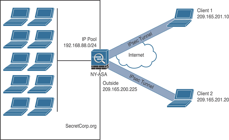
Figure 8-19 SecretCorp’s Remote Access IPsec VPN Deployment
At the end of the day, the configuration steps are very similar to the ones you have learned throughout this chapter:
Step 1. Enable ISAKMP (IKEv1).
Step 2. Create the IKEv1 (ISAKMP) policy.
Step 3. Set up tunnel and group policies.
Step 4. Define the IPsec policy.
Step 5. Configure user authentication.
Step 6. Assign an IP address.
Step 7. Create a crypto map.
Step 8. Configure traffic filtering (optional).
Step 9. Bypass NAT (optional).
Step 10. Set up split tunneling (optional).
Step 11. Define DNS and WINS addresses (optional).
Example 8-29 shows the Cisco ASA IKEv2 policy, the IPsec policy, and a dynamic crypto map to terminate the remote VPN clients.
Example 8-29 Cisco ASA Remote Access IPsec VPN IKEv2 Policy, IPsec Policy, and Dynamic Crypto Map
crypto ikev2 policy 1
 encryption aes-256
 integrity sha
 group 5
 prf sha
 lifetime seconds 86400
crypto ikev2 enable outside
!
crypto ikev2 remote-access trustpoint HeadEnd
crypto ipsec ikev2 ipsec-proposal AES256
 protocol esp encryption aes-256
 protocol esp integrity sha-1 md5
!
crypto dynamic-map Anyconnect 65535 set ikev2 ipsec-proposal AES256
crypto map outside_map 65535 ipsec-isakmp dynamic Anyconnect
crypto map outside_map interface outside
Example 8-30 shows how the group policy (SecretCorp_GP) is configured for the IKEv2 tunnels.
Example 8-30 Configuring the Group Policy in the Cisco ASA
group-policy SecretCorp_GP internal
group-policy SecretCorp_GP attributes
 vpn-tunnel-protocol ikev2
After defining the group policy, you must configure an IP address pool to assign IP addresses to the remote access VPN clients, as demonstrated in Example 8-31.
Example 8-31 Creating the IP Pool for the VPN Clients
ip local pool VPN_Pool_1 192.168.88.1-192.168.88.254 mask 255.255.255.0
Create a tunnel group, assign the IP pool, and associate the previously configured group policy, as demonstrated in Example 8-32.
Example 8-32 Creating the Tunnel Group for the Remote Access VPN Clients
tunnel-group SecretCorp_TG type remote-access
tunnel-group SecretCorp_TG general-attributes
 address-pool VPN_Pool_1
 default-group-policy SecretCorp_GP
 authentication-server-group LOCAL
You also need to specify the authentication server group under the tunnel group. In Example 8-32, local authentication is used. In large deployments, an external AAA server (such as a RADIUS server) should be used.
The next step is to configure the tunnel group IPsec attributes and enable IKEv2 authentication, as shown in Example 8-33.
Example 8-33 Configuring the Tunnel Group IPsec Attributes
tunnel-group SecretCorp_TG ipsec-attributes
 ikev2 remote-authentication certificate
 ikev2 local-authentication certificate SecretCorpHeadEnd
 tunnel-group-map enable rules
 tunnel-group-map CERT_MAP 10 SecretCorp_TG
crypto ca certificate map CERT_MAP 10
 issuer-name co SecretCorp-ROOT-CA
In Example 8-33, authentication is done using certificates. Detailed information about certificate configuration and enrollment in the Cisco ASA can be obtained from https://www.cisco.com/c/en/us/support/docs/security-vpn/public-key-infrastructure-pki/200339-Configure-ASA-SSL-Digital-Certificate-I.html.
The final step is to configure a NAT exemption rule for the IP addresses that will be assigned to the VPN clients, as demonstrated in Example 8-34.
Example 8-34 Configuring a NAT Exemption Rule for the VPN Clients
object network NETWORK_OBJ_192.168.88.0_24
 subnet 192.168.88.0 255.255.255.0
nat (inside,outside) source static any any destination static NETWORK_
OBJ_192.168.88.0_24 NETWORK_OBJ_192.168.88.0_24 no-proxy-arp route-lookup
Configuring Clientless Remote Access SSL VPNs in the Cisco ASA
The Cisco ASA supports the following SSL VPN modes:
Clientless: The remote client needs only an SSL-enabled browser to access resources on the private network of the Cisco ASAs. SSL clients can access internal resources such as HTTP, HTTPS, and even Windows file shares over the SSL tunnel.
Thin client: The remote client needs to install a small Java-based applet to establish a secure connection to the TCP-based internal resources. SSL clients can access TCP-based internal resources such as HTTP, HTTPS, SSH, and Telnet servers.
Full tunnel: The remote client needs to install an SSL VPN client first to give full access to the internal private network over an SSL tunnel. Using the full tunnel client mode, remote machines to send all IP unicast traffic such as TCP-, UDP-, or even ICMP-based traffic. SSL clients can access internal resources such as HTTP, HTTPS, DNS, SSH, and Telnet servers. Most customers prefer using the full tunnel mode option because a VPN client can be automatically pushed to a user after a successful authentication.
Typically, clientless and thin client solutions are grouped under one umbrella and classified as clientless SSL VPN.
Cisco ASA Remote-Access VPN Design Considerations
The following are several key points that you need to take into consideration before you choose your SSL VPN deployment mode:
Before you implement the SSL VPN services in Cisco ASA, you must analyze your current environment and determine which features and modes might be useful in your implementation.
Before designing and implementing the SSL VPN solution for your corporate network, you need to determine whether your users connect to your corporate network from public shared computers, such as workstations made available to guests in a hotel or computers in an Internet kiosk. In this case, using a clientless SSL VPN is the preferred solution to access the protected resources.
Network security administrators need to determine the size of the SSL VPN deployment, especially the number of concurrent users that will connect to gain network access. If one Cisco ASA is not enough to support the required number of users, clustering or load balancing must be considered to accommodate all the potential remote users.
The Cisco ASA supports load-balancing the clientless SSL VPN sessions, because the SSL VPN load-balancing configuration is identical to the remote-access IPsec load-balancing configuration.
The SSL VPN functionality on the ASAs requires that you have appropriate licenses. Make sure that you have the appropriate license for your SSL VPN deployment.
The infrastructure requirements for SSL VPNs include, but are not limited to, the following options:
ASA placement: If you are installing a new Cisco ASA, determine the location that best fits your requirements. If you plan to place it behind an existing corporate firewall, make sure you allow appropriate SSL VPN ports to pass through the firewall.
User account: Before SSL VPN tunnels are established, users must authenticate themselves to either the local database or to an external authentication server. The supported external servers include RADIUS, RADIUS one-time password (OTP), RSA SecurID, Active Directory/Kerberos, generic Lightweight Directory Access Protocol (LDAP), and Duo integration with SAML authentication. Make sure that SSL VPN users have accounts and appropriate access.
Administrative privileges: Administrative privileges on the local workstation are required for all connections with port forwarding if you want to use host mapping.
Pre-SSL VPN Configuration Steps
After analyzing the deployment considerations and selecting the SSL VPN as the remote-access VPN solution, you must follow the configuration steps described in this section to properly set up the SSL VPN so that it can be enabled on a Cisco ASA. These tasks include the following:
Enroll digital certificates (recommended)
Set up tunnel and group policies
Set up user authentication
Enrollment is the process of obtaining a certificate from a certificate authority (CA). Even though the Cisco ASA can generate self-signed certificates, use of an external CA is highly recommended. The enrollment process can be broken into three steps, as described in the following sections.
Obtain a CA/root certificate before requesting an identity certificate from the CA server. Make sure you have received a CA certificate from the server in Base64 format. Define a trustpoint and then use the crypto ca authenticate command to import the CA certificate, as demonstrated in Example 8-35.
Example 8-35 Importing the CA Certificate Manually
omar-asa(config)# crypto ca trustpoint SecretCorpSSLCert
omar-asa(config-ca-trustpoint)# enrollment terminal
omar-asa(config)# crypto ca authenticate SecretCorpSSLCert
Enter the base 64 encoded CA certificate.
End with the word "quit" on a line by itself

——-BEGIN CERTIFICATE——-
MIIC0jCCAnygAwIBAgIQIls45kcfzKZJQnk0zyiQcTANBgkqhkiG9w0BAQUFADCB
hjEeMBwGCSqGSIb3DQEJARYPamF6aWJAY2lzY28uY29tMQswCQYDVGEwJVUzEL
MAkGA1UECBMCTkMxDDAKBgNVBAcTA1JUUDEWMBQGA1UEChMNQ2lzY28gU3lzdGVt
czEMMAoGA1UECxMDVEFDMRYwFAYDVDEw1KYXppYkNBU2VydmVyMB4XDTA0MDYy
——-END CERTIFICATE——-

quit

INFO: Certificate has the following attributes:
Fingerprint:     2224ced6 55a0095e 243a5ad1 a62ed6a9
Do you accept this certificate? [yes/no]: yes
Trustpoint CA certificate accepted.
% Certificate successfully imported
Before requesting an identity certificate, you must generate the RSA key pair through ASDM or through the CLI. If you already have the RSA keys generated that you want to use for SSL encryption, you can skip creating new ones. After generating the RSA keys, request an identity certificate to be used for SSL VPN. In Example 8-36, the CLI configuration for manual enrollment is shown. The enrollment terminal subcommand in SecretCorpSSLCert configuration is used to declare manual enrollment of the CA server. This trustpoint uses the SecreCorpSSLCert RSA key.
Example 8-36 Manual Certificate Enrollment
omar-asa# configure terminal
omar-asa(config)# domain-name secretcorp.org
omar-asa(config)# crypto key generate rsa label SecretCorpSSLRSA
The name for the keys will be: omar-asa.secretcorp.org

% The key modulus size is 1024 bits
% Generating 1024 bit RSA keys, keys will be non-exportable...[OK]

omar-asa(config)# crypto ca trustpoint SecretCorpSSLCert
omar-asa(ca-trustpoint)# keypair SecretCorpSSLRSA
omar-asa(ca-trustpoint)# id-usage ssl-ipsec
omar-asa(ca-trustpoint)# no fqdn
omar-asa(ca-trustpoint)# subject-name CN=omar-asa
omar-asa(ca-trustpoint)# enrollment terminal
omar-asa(ca-trustpoint)# crypto ca enroll SecretCorpSSLCert
After the identity certificate is approved by the CA server administrator, use the crypto ca import command to import the Base64-encoded ID certificate, as demonstrated in Example 8-37.
Example 8-37 Importing the ID Certificate
omar-asa(config)# crypto ca import SecretCorpSSLCert certificate

% The fully-qualified domain name in the certificate will be: omar-asa.secretcorp.
org
Enter the base 64 encoded certificate.
End with the word "quit" on a line by itself

——-BEGIN CERTIFICATE——-
MIIECDCCA7KgAwIBAgIKHJGvRQAAAAAADTANBgkqhkiG9w0BAQUFADCBhjEeMBwG
CSqGSIb3DQEJARYPamF6aWJAY2lzY28uY29tMQswCQYDVGEwJVUzELMAkGA1UE
CBMCTkMxDDAKBgNVBAcTA1JUUDEWMBQGA1UEChMNQ2lzY28gU3lzdGVtczEMMAoG
A1UECxMDVEFDMRYwFAYDVDEw1KYXppYkNBU2VydmVyMB4XDTA0MDkwMjAyNTgw
NVoXDTA1MDkwMjAzMDgwNVowLzEQMA4GA1UEBRMHNDZmZjUxODEbMBkGCSqGSIb3
SGzFQHtnqURciJBtay9RNnMpZmZYpfOHzmeFmQ==
——-END CERTIFICATE——-
You must activate the identity certificate to the interface terminating the VPN tunnels, as demonstrated in Example 8-38. In Example 8-38, the interface terminating the VPN tunnels is the outside interface.
Example 8-38 Activating the Identity Certificate
omar-asa(config)# ssl trust-point SecretCorpSSLCert outside
Understanding the Remote Access VPN Attributes and Policy Inheritance Model
As you learned earlier in this chapter, the Cisco ASA uses an inheritance model when it pushes network and security policies to the end-user sessions. Using this model, you can configure policies at the following three policy locations:
Under the default group policy
Under the user’s assigned group policy
Under the specific user’s policy
In the inheritance model, a user receives the attributes and policies from the user policy, which inherits its attributes and policies from the user group policy, which in turn receives its attributes and policies from the default group policy, as illustrated in Figure 8-20. A user with ID derek receives a traffic ACL and an assigned IP address from the user policy, the domain name from the user group policy, and Windows Internet Naming Server (WINS) information along with the number of simultaneous logins from the default group policy.

Figure 8-20 Cisco ASA Attributes and Policies Inheritance Model
After these policies are defined, they must be bound to a tunnel group where users terminate their sessions. This way, a user who establishes his or her VPN session to a tunnel group inherits all the policies mapped to that tunnel. The tunnel group defines a VPN connection profile, of which each user is a member.
Configuring Clientless SSL VPN Group Policies
You need to configure the user group and default group policies. This group policy allows only clientless SSL VPN tunnels to be established and strictly rejects all the other tunneling protocols. If you would rather assign attributes to a default group policy, modify DfltGrpPolicy (System Default). Any attribute that is modified under DfltGrpPolicy is propagated to any user group policy that inherits that attribute. A group policy name other than DfltGrpPolicy is treated as a user group policy.
Example 8-39 demonstrates how to define a user group policy called ClientlessGroupPolicy. This policy allows only the clientless tunnels to be terminated on the group, by using the webvpn keyword.
Example 8-39 Clientless SSL VPN Group Policy Definition
omar-asa(config)# group-policy ClientlessGroupPolicy internal
omar-asa(config)# group-policy ClientlessGroupPolicy attributes
omar-asa(config-group-policy)# vpn-tunnel-protocol webvpn
The user, group, and default group polices can be applied to clientless, AnyConnect, and IPsec-based remote-access VPN tunnels. The clientless SSL VPN–specific attributes are discussed in detail in the next few sections of this chapter.
Configuring the Tunnel Group for Clientless SSL VPN
You can configure a tunnel group, also known as a connection profile, as demonstrated in Example 8-40.
Example 8-40 Configuring the Tunnel Group for Clientless SSL VPN
omar-asa(config)# tunnel-group SecretCorpClientlessTunnel type remote-access
omar-asa(config)# tunnel-group SecretCorpClientlessTunnel general-attributes
omar-asa(config-tunnel-general)# default-group-policy ClientlessGroupPolicy
omar-asa(config-tunnel-general)# exit
omar-asa(config)# dns server-group DefaultDNS
omar-asa(config-dns-server-group)# domain-name ssecretcorp.org
omar-asa(config-dns-server-group)# name-server 192.168.3.4
After configuring a connection profile, you can define a URL that users can employ to connect to this tunnel group. This is beneficial if you want to create a specific URL for each connection profile you create and distribute the URL accordingly so that users do not have to decide to which connection profile they should connect.
You define a specific URL by modifying the connection profile. Example 8-41 demonstrates how to specify a group-url of https://sslvpn.secretcorp.org/SecretCorpClientless for SecretCorpClientlessTunnel.
Example 8-41 Specifying the Tunnel Group URL
omar-asa(config)# tunnel-group SecretCorpClientlessTunnel webvpn-attributes
omar-asa(config-tunnel-webvpn)# group-url https://sslvpn.secretcorp.org/
SecretCorpClientless enable
Configuring User Authentication for Clientless SSL VPN
Cisco ASA supports a number of authentication mechanisms and databases:
RADIUS
NT domain
Kerberos
SDI
LDAP
Digital certificates
Smart cards
SAML
Local databases
For small organizations, a local database can be set up for user authentication. For medium to large SSL VPN deployments, it is highly recommended that you use an external authentication server, such as RADIUS or Kerberos, as the user authentication database. If you are deploying the SSL VPN feature for a few users, use the local database.
The Cisco ASA supports SAML 2.0 for Clientless VPN. With SAML 2.0, VPN users are able to input their credentials only one time when they switch between Clientless VPN and other SAAS applications outside of the private network. For instance, an organization may have Duo enabled for single sign-on (SSO) multifactor authentication and has accounts on Service-Now, GitHub, Microsoft ADFS, or Dropbox that have been SAML 2.0 SSO enabled. When you configure the Cisco ASA to support SAML 2.0 SSO as a Service Provider (SP), end users are able to sign in once and have access to all these services, including Clientless VPN.
In Example 8-42, two accounts, hannah and adminuser, are configured for user authentication. The hannah account, with a password of C1$c0123, is used for SSL VPN user authentication, whereas adminuser, with a password of @dm1n123, is used to manage the Cisco ASA.
Example 8-42 Local User Accounts
omar-asa(config)# username hannah password C1$c0123
omar-asa(config)# username adminuser password @dm1n123
Many organizations use either a RADIUS server or Kerberos to leverage their existing Active Directory infrastructure for user authentication. Before configuring an authentication server on Cisco ASA, you must specify authentication, authorization, and accounting (AAA) server groups. User passwords are sent as encrypted values from the Cisco ASA to the RADIUS server. This protects this critical information from an intruder. The Cisco ASA hashes the password, using the shared secret that is defined on the Cisco ASA and the RADIUS server.
After defining the authentication server group, you need to bind it to the SSL VPN process under a tunnel group. Example 8-43 shows how a RADIUS server can be defined. The RADIUS group name is Radius, and it is located toward the inside interface at 192.168.10.123. The shared secret is R4diuzkeyz!.
Example 8-43 Configuring the Cisco ASA to Authenticate Users Using a RADIUS Server
omar-asa(config)# aaa-server Radius protocol radius
omar-asa(config)# aaa-server Radius (inside) host 192.168.10.123
omar-asa(config-aaa-server-host)# key R4diuzkeyz!
omar-asa(config-aaa-server-host)# exit
Enabling Clientless SSL VPN
The clientless configuration of SSL VPN describes the mandatory steps for enabling SSL VPNs and setting up the user interface for clientless SSL VPN users. The following sections focus on the clientless SSL VPN users who want to access internal corporate resources but do not have an SSL VPN client loaded on their workstations. These users typically access protected resources from shared workstations or even from hotels or Internet cafes. The clientless configuration on Cisco ASA can be broken down into the following subsections:
Enable clientless SSL VPN on an interface
Configure SSL VPN portal customization
Configure bookmarks
Configure WebType ACLs
Configure application access
Configure client-server plug-ins
The first step in setting up a clientless SSL VPN on the Cisco ASA is to enable an SSL VPN on the interface that will terminate the user session. If SSL VPN is not enabled on the interface, the Cisco ASA does not accept any connections, even if SSL VPN is globally enabled.
Example 8-44 shows that SSL VPN functionality is enabled on the outside interface. Historically, SSL VPN has been referred to as WebVPN. Thus, why you see the webvpn configuration command.
Example 8-44 Enabling SSL VPN on the Outside Interface
omar-asa(config)# webvpn
omar-asa(config-webvpn)# enable outside
After SSL VPN is enabled on an interface, the Cisco ASA is ready to accept the connections. However, you still need to go through other configuration steps to successfully accept user connections and to allow traffic to pass through.
Configuring WebType ACLs
The Cisco ASA enables network administrators to further their clientless SSL VPN security by configuring WebType access control lists to manage access to the following:
Web
Telnet
SSH
Citrix
FTP
File and email servers
All types of traffic
These ACLs affect only the clientless SSL VPN traffic and are processed in sequential order until a match is found. If an ACL is defined but no match exists, the default behavior on the Cisco ASA is to drop packets. On the other hand, if no WebType ACL is defined, Cisco ASA allows all traffic to pass through it.
Moreover, this feature allows these ACLs to be downloaded from a RADIUS server such as the Cisco Identity Services Engine (ISE) through the use of vendor-specific attributes (VSA). This permits central control and management of user access into the corporate network because ACL definitions are offloaded to an external server.
The Cisco ASA allows you to filter based on the following protocols for all types of URLs:
CIFS
Citrix
FTP
HTTP/HTTPS
IMAP4/POP3/SMTP
NFS
Smart tunnel
SSH
Telnet
VNC
RDP
If you want to include all URLs that are not explicitly matched in the ACL, include an asterisk (*) as a wildcard.
Example 8-45 shows a WebType ACL called Restrict being configured to allow http://internal.secretcorp.org. This ACL is then applied to ClientlessGroupPolicy.
Example 8-45 Defining a WebType ACL
omar-asa(config)# access-list Restrict webtype permit url
http://internal.secretcorp.org
omar-asa(config)# group-policy ClientlessGroupPolicy attributes
omar-asa(config-group-policy)# webvpn
omar-asa(config-group-webvpn)# filter value Restrict
Configuring Application Access in Clientless SSL VPNs
Cisco ASA allows clientless SSL VPN users to access applications that reside on the protected network. Application access supports only applications that use TCP ports such as SSH, Outlook, and Remote Desktop. The Cisco ASA allows the following two methods to configure application access:
Port forwarding
Smart tunnels
Using port forwarding, the clientless SSL VPN users can access corporate resources over the known and fixed TCP ports such as Telnet, SSH, Terminal Services, SMTP, and so on. The port-forwarding feature requires you to install Oracle’s Java Runtime Environment (JRE) and configure applications on the end user’s PC. If users are establishing the SSL VPN tunnel from public computers, such as Internet kiosks or web cafes, they might not be able to use this feature because JRE installation requires administrative rights on the client computer. Port forwarding is supported only on the 32-bit-based operating systems.
As discussed earlier, port forwarding provides access to applications that use static TCP ports. It modifies the HOSTS files on a host so that traffic can be redirected to a forwarder that encapsulates traffic over the SSL VPN tunnel. Additionally, with port forwarding, the Cisco ASA administrator needs to know to which addresses and ports the SSL VPN users will connect and requires the SSL VPN users to have admin rights to modify the HOSTS file. To overcome some of the challenges related to port forwarding, Cisco ASA presents a new method to tunnel application-specific traffic called smart tunnels. Smart tunnels define which applications can be forwarded over the SSL VPN tunnel, whereas port forwarding defines which TCP ports can be forwarded over the tunnel.
Smart tunnels do not require administrators to preconfigure the addresses of the servers running the applications or the ports for those applications. In fact, smart tunnels work at the application layer by establishing a Winsock 2 connection between the client and the server. A stub is loaded into each process for the application that needs to be tunneled and then intercepts socket calls through the Cisco ASA. Thus, the principal benefit of smart tunnels over port forwarding is that users do not need to have administrative rights to use this feature.
Smart tunnels provide better performance than port forwarding, and the user experience is simpler because users don’t need to configure their applications for a loopback address and for a specific local port.
Smart tunnels require browsers with ActiveX, Java, or JavaScript support. Both 32- and 64-bit-based operating systems are supported.
Configuring Client-Based Remote-Access SSL VPNs in the Cisco ASA
As you learned earlier in this chapter, clientless VPN application does not provide full network access to your remote users. If you want your users to have full network connectivity from their remote workstations, similar to what they would have with remote-access IPsec but by using SSL VPN, you can implement the full tunnel mode functionality on the Cisco ASA. Using the full tunnel client mode, remote machines can send all IP unicast traffic, including TCP-, UDP-, or even ICMP-based packets. SSL clients can access internal resources via HTTP, HTTPS, SSH, or Telnet, to name a few.
Many enterprises are in the process of migrating from an existing IPsec-based deployment. Their main motivation is that the Cisco AnyConnect Secure Mobility Client is easy to deploy and maintain, has a smaller package size, requires no machine reboots during client installation, and is easy to configure.
In the full tunnel mode, Cisco AnyConnect Secure Mobility Client can be pushed to or installed on the remote workstations after a successful authentication. After it is installed, you can choose to keep the client installed permanently and thus reduce the connection time for the remote user.
Setting Up Tunnel and Group Policies
As discussed earlier in this chapter, the Cisco ASA uses an inheritance model when it pushes network and security policies to the end-user sessions. Using this model, you can configure policies at the following three policy locations:
Under the default group policy
Under the user’s assigned group policy
Under the specific user’s policy
In the inheritance model, a user receives the attributes and policies from the user policy, which inherits its attributes and policies from the user group policy, which in turn receives its attributes and policies from the default group policy.
After defining these policies, you must bind them to a tunnel group where users terminate their sessions. This way, a user who establishes her VPN session to a tunnel group inherits all the policies mapped to that tunnel. The tunnel group defines a VPN connection profile, of which each user is a member. Configure the user group and default group policies.
The user, group, and default group polices can be applied to clientless, Cisco AnyConnect Secure Mobility Client, and IPsec-based remote-access VPN tunnels. The Cisco AnyConnect Secure Mobility Client SSL VPN–specific attributes are discussed in detail in the next few sections of this chapter.
Example 8-46 illustrates how to define a user group policy called Cisco AnyConnectGroupPolicy. This policy allows only the AnyConnect tunnels to be terminated on the group, by using the svc keyword.
Example 8-46 Group Policy Definition
omar-asa(config)# group-policy AnyConnectGroupPolicy internal
omar-asa(config)# group-policy AnyConnectGroupPolicy attributes
omar-asa(config-group-policy)# vpn-tunnel-protocol svc
Configure a tunnel group, also known as connection profile, as demonstrated in Example 8-47.
Example 8-47 Tunnel Group Definition
omar-asa(config)# tunnel-group SecretCorpAnyConnect type remote-access
omar-asa(config)# tunnel-group SecretCorpAnyConnect general-attributes
omar-asa(config-tunnel-general)# default-group-policy AnyConnectGroupPolicy
After configuring a connection profile, you can define a specific URL for users to connect to this tunnel group. This is beneficial if you want to create a specific URL for each connection profile you design. Distribute the URL accordingly so that users do not have to decide to which connection profile to connect.
Example 8-48 shows how a RADIUS server is defined. The RADIUS group name is secretcorp-radius-group, and it is located toward the inside interface at 192.168.1.123. The shared secret is R4diuzkeyz!. The RADIUS server is added to SecretCorpAnyConnect.
Example 8-48 Defining the RADIUS Server for Client-Based SSL VPN
omar-asa(config)# aaa-server Radius protocol radius
omar-asa(config)# aaa-server secretcorp-radius-group (inside) host 192.168.1.123
omar-asa(config-aaa-server-host)# key R4diuzkeyz!
omar-asa(config-aaa-server-host)# exit
omar-asa(config)# tunnel-group SecretCorpAnyConnect general-attributes
omar-asa(config-tunnel-general)# authentication-server-group secretcorp-radius-group
Deploying the AnyConnect Client
Cisco AnyConnect Secure Mobility Client VPN client can be installed on a user’s computer using one of these methods:
Web-enabled mode: With this method, the client is downloaded to a user’s computer through a browser. The user opens a browser and references the IP address or the FQDN of Cisco ASA to establish an SSL VPN tunnel. The user is presented with the standard SSL VPN logon page and is prompted for credentials.
Standalone mode: With this method, the client is downloaded as a standalone application from a file server or directly from Cisco.com. The Windows Installer is executed to install the client to the workstation. If the client is not preconfigured, the user needs to specify the IP address or FQDN of the Cisco ASA, the tunnel group to connect to, the username, and the associated password.
In the case of mobile devices (such as iPhones, iPads, and Android devices), Cisco AnyConnect Secure Mobility Client can be downloaded directly from the Apple App Store or from Google Play, respectively.
The configuration of Cisco AnyConnect Secure Mobility Client VPN client is a two-step process:
Step 1. Load the Cisco AnyConnect Secure Mobility Client package.
Step 2. Define Cisco AnyConnect Secure Mobility Client VPN client attributes.
After loading the Cisco AnyConnect Secure Mobility Client package in the Cisco ASA’s configuration, you can define client parameters such as the IP address that the client should receive via ASDM. Before a Cisco AnyConnect Secure Mobility Client SSL VPN tunnel is functional, you have to configure the following two required actions:
Enabling Cisco AnyConnect Secure Mobility Client connections
Address pool definition
Optionally, you can define other attributes to enhance the functionality of the Cisco AnyConnect Secure Mobility Client configuration, including the following:
Split tunneling
DNS and WINS assignment
Keeping SSL VPN client installed
DTLS
Configuring traffic filters
Configuring a tunnel group
During the SSL VPN tunnel negotiations, an IP address is assigned to the VPN adapter of the Cisco AnyConnect Secure Mobility Client. The client uses this IP address to access resources on the protected side of the tunnel. Cisco ASA supports three different methods to assign an IP address back to the client:
Local address pool
DHCP server
RADIUS server
Many organizations prefer assigning an IP address from the local pool of addresses for flexibility. You assign the IP address by configuring an address pool and then linking the pool to a group policy. You can either create a new pool of addresses or select a preconfigured address pool.
Example 8-49 demonstrates how SSL VPN (WebVPN) is enabled on the outside interface (similarly to the clientless SSL VPN configuration you learned earlier in this chapter). In Example 8-49, a local IP pool is configured to assign IP addresses to the VPN clients. The pool is then assigned to the AnyConnectGroupPolicy group policy.
Example 8-49 Enabling SSL VPN and Configuring the IP Pool
omar-asa(config)# webvpn
omar-asa(config-webvpn)# enable outside
omar-asa(config)# ip local pool SSLVPNPool 192.168.88.1-192.168.88.100 mask
255.255.255.0
omar-asa(config)# group-policy AnyConnectGroupPolicy attributes
omar-asa(config-group-policy)# address-pools value SSLVPNPool
Understanding Split Tunneling
After the tunnel is established, the default behavior of the Cisco AnyConnect Secure Mobility Client is to encrypt traffic to all the destination IP addresses. This means that if an SSL VPN user wants to browse to http://www.cisco.com over the Internet, as illustrated in Figure 8-21, the packets are encrypted and sent to Cisco ASA. After decrypting them, the Cisco ASA searches its routing table and forwards the packet to the appropriate next-hop IP address in clear text. These steps are reversed when traffic returns from the web server and is destined to the SSL VPN client.

Figure 8-21 VPN Traffic with No Split Tunneling
The behavior illustrated in Figure 8-21 might not always be desirable for the following two reasons:
Traffic destined to the nonsecure networks traverses over the Internet twice: once encrypted and once in clear text.
The Cisco ASA handles extra VPN traffic destined to the nonsecure subnet. The Cisco ASA analyzes all traffic leaving and coming from the Internet.
With split tunneling, the Cisco ASA notifies the Cisco AnyConnect Secure Mobility Client about the secured subnets. The VPN client, using the secured routes, encrypts only those packets that are destined for the networks behind the security appliance. With split tunneling, the remote computer is susceptible to threat actors, who can potentially take control over the computer and direct traffic over the tunnel. To mitigate this behavior, a personal firewall is highly recommended on the Cisco AnyConnect Secure Mobility Client workstations.
Split tunneling can be configured under a user policy, user group policy, or default group policy. In split tunneling configurations, you define the traffic that will be encrypted by creating an ACL and assigning it to the group policy attributes, as demonstrated in Example 8-50.
Example 8-50 Configuring Split Tunneling
omar-asa(config)# access-list SplitTunnelList standard permit 192.168.0.0
255.255.255.0
omar-asa(config)# group-policy AnyConnectGroupPolicy attributes
omar-asa(config-group-policy)# split-tunnel-policy tunnelspecified
omar-asa(config-group-policy)# split-tunnel-network-list value SplitTunnelList
Cisco AnyConnect Secure Mobility Client supports split DNS functionality for Windows and macOS operating systems. It tunnels any DNS queries that match specified domain names to the private corporate DNS server. True split DNS allows tunnel access only to DNS requests that match the domains pushed to the client by the ASA. This DNS traffic is encrypted; however, if the DNS requests do not match the domains sent by the ASA, Cisco AnyConnect Secure Mobility Client permits the client operating system’s DNS resolver to submit the hostname in the clear for DNS resolution.
Understanding DTLS
The Datagram Transport Layer Security (DTLS), defined in RFC 6347, provides security and privacy for UDP packets. This allows UDP-based applications to send and receive traffic in a secure fashion without concern about packet tampering and message forgery. Thus, applications can avoid the delays associated with TCP but still communicate securely by using DTLS.
Cisco AnyConnect Client supports both SSL and DTLS transport protocols. DTLS is enabled, by default, on the security appliance. If it is enabled and UDP is blocked or filtered, communication between the client and the security appliance reverts to the TCP-based SSL protocol.
Configuring Remote Access VPNs in FTD
Cisco FTD supports remote access SSL and IPsec-IKEv2 VPNs. Many organizations use the Cisco AnyConnect Secure Mobility Client (or AnyConnect for short) in combination with Cisco FTD devices to provide secure SSL and IPsec-IKEv2 and additional protections for remote users. AnyConnect is the only client supported on endpoint devices for remote VPN connectivity to Cisco FTD devices. The client gives remote users the benefits of an SSL or IPsec-IKEv2 VPN client without the need for network administrators to install and configure clients on remote computers.
The following are the features related to remote access VPN supported in Cisco FTD devices:
SSL and IPsec-IKEv2 remote access using the Cisco AnyConnect Secure Mobility Client.
Cisco FMC support for all combinations such as IPv6 over an IPv4 tunnel.
Configuration support on both FMC and FDM.
Support for multiple interfaces and multiple AAA servers.
Support for both FMC and FTD high-availability environments.
Rapid Threat Containment support using RADIUS Change of Authorization (CoA) or RADIUS dynamic authorization.
AAA server authentication using self-signed or CA-signed identity certificates.
AAA username and password-based remote authentication using RADIUS server or LDAP or AD.
RADIUS group and user authorization attributes as well as RADIUS accounting.
Double authentication support using an additional AAA server for secondary authentication.
NGFW Access Control policy integration using VPN Identity.
VPN Tunneling address assignment.
Split tunneling and Split DNS support.
Client Firewall ACLs.
Session timeouts for maximum connect and idle time.
VPN dashboard widget in FMC showing VPN users by various characteristics, such as duration and client application.
Remote-access VPN events, including authentication information such as username and OS platform.
Tunnel statistics available using the FTD Unified CLI.
Using the Remote Access VPN Policy Wizard
You can use the Remote Access VPN Policy Wizard in the Firepower Management Center (FMC) to easily configure SSL and IPsec-IKEv2 remote-access VPNs with basic capabilities. You can then enhance the policy configuration (if desired) and deploy it to your Cisco FTD devices.
The following are the steps to configure SSL and IPsec-IKEv2 remote-access VPNs with the Remote Access VPN Policy Wizard.
Step 1. To start the Remote Access VPN Policy Wizard in the Cisco FMC, navigate to Devices > VPN > Remote Access. Click Add to create a new Remote Access VPN Policy. The wizard walks you through a basic policy configuration. You must complete all the steps in order for the wizard to create a new policy. Keep in mind that the policy is not saved if you cancel before completing the wizard.
Step 2. After you start the wizard, the screen shown in Figure 8-22 is displayed. Enter a name and an optional description for the new policy. Select VPN Protocols and Target Devices, as demonstrated in Figure 8-22. You can select SSL or IPsec-IKEv2, or both the VPN protocols. The Cisco FTD devices selected in the screen shown in Figure 8-22 will function as your remote-access VPN gateways for the VPN client users. You can select the devices from the list or add a new device.

Figure 8-22 The FMC Remote Access VPN Policy Wizard Policy Assignment
Step 3. Configure the Connection Profile and Group Policy settings, as demonstrated in Figure 8-23. A connection profile specifies a set of parameters that define how the remote users connect to the VPN device. The parameters include settings and attributes for authentication, address assignments to VPN clients, and group policies. The Cisco FTD provides a default connection profile named DefaultWEBVPNGroup when you configure a remote access VPN policy. The Connection Profile Name used in this example is secretcorp-RA-VPN-policy-1.

Figure 8-23 Configuring the Remote Access VPN Connection Profile in Cisco FTD Devices
Step 4. You can also set the AAA method (AAA, certificates, or both) and the AAA servers that will be used for the VPN connections, as shown in Figure 8-23. If you do not have an authentication server defined, you can click the plus sign (+) to define a new AAA server. The screen shown in Figure 8-24 is displayed after you click the plus sign (+) to define a new AAA server.

Figure 8-24 Adding a New AAA Server (RADIUS Server Group)
Step 5. Figure 8-25 shows the authentication server that you configured (RADIUS-1 in this example). You can select the same RADIUS server or a different one for authorization (Authorization Server) or accounting (Accounting Server). In the example shown in Figure 8-25, the same RADIUS server (RADIUS-1) is selected as the authentication, authorization, and accounting server.

Figure 8-25 Configuring the Authentication, Authorization, and Accounting Servers in the Connection Policy
Step 6. A group policy is a set of attribute and value pairs, stored in a group policy object, that define the remote-access VPN experience for VPN users. You can configure different attributes in the group policy such as user authorization profile, IP addresses, AnyConnect settings, VLAN mapping, and user session settings. The RADIUS authorization server assigns the group policy, or it is obtained from the current connection profile. Figure 8-26 shows the client address assignment section for the group policy.
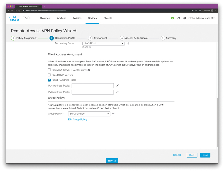
Figure 8-26 The Client Address Assignment Section for the Group Policy
Step 7. Click the pencil icon to add an Address Pool. The screen shown in Figure 8-27 is displayed.
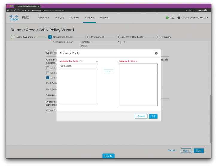
Figure 8-27 Adding an Address Pool
Step 8. To add an IPv4 pool click the plus sign next to Available IPv4 Pools. The screen shown in Figure 8-28 is displayed. In Figure 8-28, the IPv4 address pool is called Pool-1 and the pool will assign IP addresses from 10.10.10.1 through 10.10.10.100. Clients addresses are configured with a 24-bit (/24 or 255.255.255.0) subnet mask.
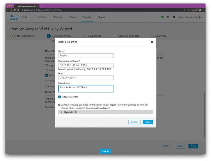
Figure 8-28 Adding an IPv4 Pool
Once you click Save, the screen shown in Figure 8-29 is displayed. Add the newly created pool (Pool-1 in this example) to the Selected IPv4 Pools section on the right of the screen, as shown in Figure 8-29.
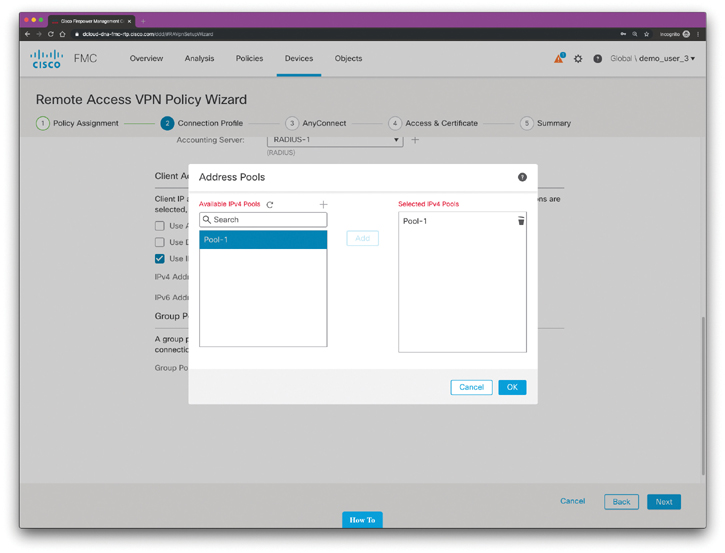
Figure 8-29 Selecting the IPv4 Pool
Step 9. Select the AnyConnect Client Image that the VPN users will use to connect to the remote access VPN. After you configure the remote access VPN policy, VPN users can enter the IP address of the configured device interface in their browser to download and install the AnyConnect client. The AnyConnect Client Image page shown in Figure 8-30 is displayed.
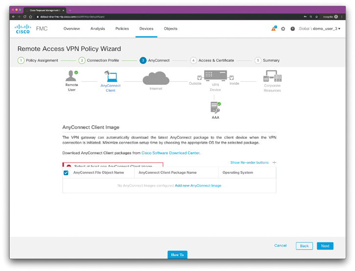
Figure 8-30 Adding AnyConnect Images to the Cisco FTD Device(s)
Click Add new AnyConnect Image to add the AnyConnect software image for VPN clients. The screen shown in Figure 8-31 is displayed. Enter a name for the AnyConnect file and browse your local computer to locate the AnyConnect image to be uploaded to the Cisco FTD device. In Figure 8-31, the user-friendly name for the file is MAC-AnyConnect. A Mac OS X AnyConnect image is used in this example. You can also enter an optional description, as shown in Figure 8-31.

Figure 8-31 Uploading the AnyConnect File
You can click additional AnyConnect images by clicking the plus sign (+) shown in Figure 8-32.
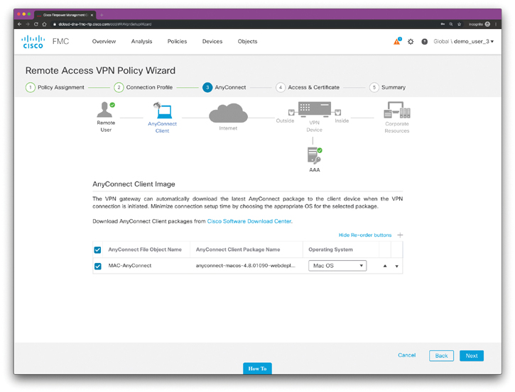
Figure 8-32 Adding Additional AnyConnect Client Images
Step 10. Select the Network Interface and Identity Certificate. Interface objects segment your network to help you manage and classify traffic flow. A security zone object combines (groups) interfaces. These groups may span multiple Cisco FTD devices. In addition, you can configure multiple zones interface objects on a single device. There are two types of interface objects: security zones and interface groups. An interface can belong to only one security zone. In contrast, an interface can belong to multiple interface groups (and to one security zone). You can add the network interface for incoming VPN connections in the wizard screen shown in Figure 8-33.
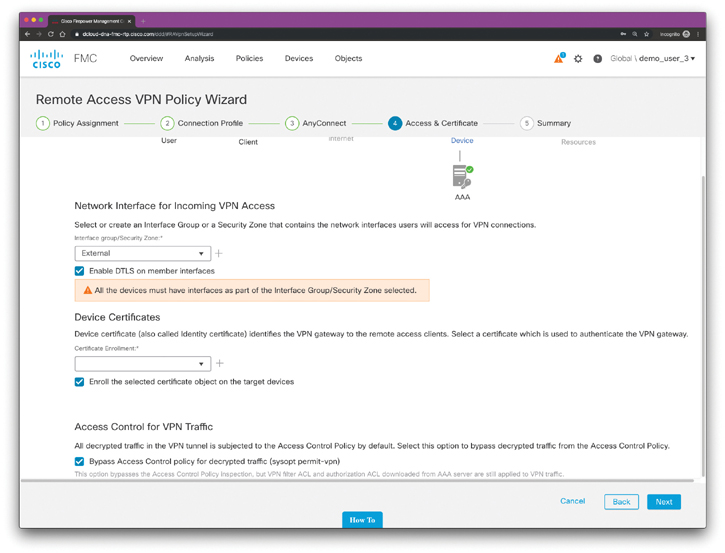
Figure 8-33 Adding the Network Interface for Incoming VPN Connections
You can perform digital certificate enrollment for the Cisco FTD device in the wizard. To enroll and obtain a new certificate, click the plus sign next to Certificate Enrollment in the screen shown in Figure 8-33. The screen shown in Figure 8-34 is displayed.

Figure 8-34 Adding Certificate Enrollment
Step 11. View the Summary of the Remote Access VPN policy configuration. The Summary page displays all the remote access VPN settings you have configured so far and provides links to the additional configurations that need to be performed before deploying the remote-access VPN policy on the selected devices. After you complete the wizard, it returns to the policy listing page. You can then set up the DNS configuration for the VPN clients, configure access control for VPN users, and enable NAT exemption (if necessary) to complete a basic RA VPN Policy configuration. After completing these additional configuration steps, deploy the configuration and establish VPN connections.
When the AnyConnect negotiates a connection with the security appliance, the client connects using TLS and, optionally, using the Datagram Transport Layer Security (DTLS) protocol to prevent latency and bandwidth problems associated with some SSL connections. DTLS also improves the performance of real-time applications that are sensitive to packet delays.
Troubleshooting Cisco FTD Remote Access VPN Implementations
The Cisco FTD provides several debug commands that can be useful to troubleshoot remote access VPN connections. The command debug feature [ subfeature] [ level] can be used to enable debugging for specific features in Cisco FTD devices. The level option might not be available for all features. The default debugging level is 1.
When you have multiple clients connecting via VPN, troubleshooting can be difficult given the size of the logs. To ease the troubleshooting task, you can use the debug webvpn condition command to set up filters to target your debug process more precisely. The following is the syntax of the debug webvpn condition command:
debug webvpn condition {group name | p-ipaddress ip_address
[{subnet subnet_mask | prefix length}] | reset | user name}
When you use the group name keyword, the debug filters on a group policy (not a tunnel group or connection profile). The p-ipaddress ip_address [{subnet subnet_mask | prefix length}] filters on the public IP address of the client. The subnet mask (for IPv4) or prefix (for IPv6) is optional. You can use the reset option to reset all filters, and you can use the no debug webvpn condition command to turn off a specific conditional debug.
Example 8-51 shows an example of enabling a conditional debug to filter messages for the connections associated with the user hannah.
Example 8-51 Enabling Conditional Debugs to Filter Connections by VPN Users
firepower# debug webvpn condition user hannah
firepower# show webvpn debug-condition
INFO: Webvpn conditional debug is turned ON
INFO: User name filters:
INFO: hannah
firepower# debug webvpn
INFO: debug webvpn  enabled at level 1.
firepower# show debug
debug webvpn  enabled at level 1
INFO: Webvpn conditional debug is turned ON
INFO: User name filters:
INFO: hannah
Configuring Site-to-Site VPNs in FTD
Cisco FTD devices support site-to-site IPsec tunnels using both IKEv1 and IKEv2. Similarly to the Cisco ASA, the Cisco FTD also supports certificates and automatic or pre-shared keys for authentication. IPv4 and IPv6 are both supported in Cisco FTD site-to-site VPN deployments.
The following are the steps to configure site-to-site IPsec in Cisco FTD devices:
Step 1. To configure a site-to-site VPN in a Cisco FTD, you have to create a new site-to-site VPN topology by navigating to Devices > VPN > Site-to-Site VPN in the Cisco FMC. The screen shown in Figure 8-35 is displayed, allowing you to add a new VPN topology by clicking the Firepower Device or Firepower Threat Defense Device link.

Figure 8-35 VPN Topologies for Site-To-Site VPN
Step 2. Let’s create a new VPN topology by clicking the Firepower Device link. The screen shown in Figure 8-36 is displayed.
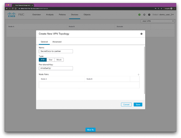
Figure 8-36 Creating a New VPN Topology for Site-to-Site VPN
Step 3. Enter a unique name for the new topology and specify a topology type, as demonstrated in Figure 8-36. Point-to-point (PTP) deployments establish a VPN tunnel between two endpoints. Hub and Spoke (Star) topologies establish a group of VPN tunnels connecting a hub endpoint to a group of spoke nodes. Full Mesh (Mesh) deployments establish a group of VPN tunnels among a set of endpoints.
Step 4. Specify the node pairs by clicking the plus sign (+) shown in Figure 8-36. After you click the plus sign, the screen shown in Figure 8-37 is displayed.
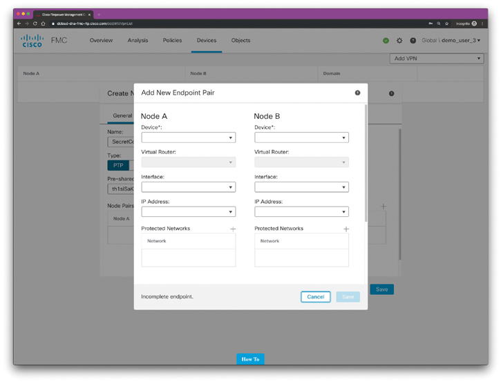
Figure 8-37 Adding the New Endpoint Pair
Step 5. Select the devices you want to configure to establish the site-to-site VPN tunnel, their associated interfaces, and the IP addresses. Also specify the protected networks at each VPN endpoint device.
Exam Preparation Tasks
As mentioned in the section “How to Use This Book” in the Introduction, you have a couple of choices for exam preparation: the exercises here, Chapter 12, “Final Preparation,” and the exam simulation questions in the Pearson Test Prep Software Online.
Review All Key Topics
Review the most important topics in this chapter, noted with the Key Topic icon in the outer margin of the page. Table 8-2 lists these key topics and the page numbers on which each is found.
Table 8-2 Key Topics for Chapter 8
Key Topic Element |
Description |
Page Number |
List |
Identifying the different protocols that have been used throughout the years for VPN implementations |
|
List |
Identifying the different VPN implementation modes |
|
Section |
An Overview of IPs |
|
List |
Understanding the protocols used to encapsulate the data over an IPsec VPN tunnel |
|
Section |
NAT Traversal (NAT-T) |
|
List |
Comparing the differences between IKEv1 and IKEv2 |
|
Section |
SSL VPNs |
|
Section |
Cisco AnyConnect Secure Mobility |
|
Section |
Traditional Site-to-Site VPNs in Cisco IOS and Cisco IOS-XE Devices |
|
Section |
Tunnel Interfaces |
|
Section |
GRE over IPsec |
|
Section |
More About Tunnel Interfaces |
|
Tip |
Understanding what are static and dynamic VTIs |
|
Section |
Multipoint GRE (mGRE) Tunnels |
|
Section |
DMVPN |
|
Section |
GETVPN |
|
Section |
FlexVPN |
|
An example of a FlexVPN deployment |
||
Section |
Debug and Show Commands to Verify and Troubleshoot IPsec Tunnels |
|
Section |
Configuring Site-to-Site VPNs in Cisco ASA Firewalls |
|
Section |
Configuring IPsec Remote Access VPN in the Cisco ASA |
|
List |
Identifying SSL VPN modes |
|
Section |
Cisco ASA Remote-Access VPN Design Considerations |
|
Section |
Pre-SSL VPN Configuration Steps |
|
Section |
Understanding the Remote Access VPN Attributes and Policy Inheritance Model |
|
Section |
Deploying the AnyConnect Client |
|
Section |
Understanding Split Tunneling |
|
Section |
Configuring Remote Access VPN in FTD |
|
Section |
Using the Remote Access VPN Policy Wizard |
|
Section |
Troubleshooting Cisco FTD Remote Access VPN Implementations |
|
Section |
Configuring Site-to-Site VPNs in FTD |
Define Key Terms
Define the following key terms from this chapter and check your answers in the glossary:
Review Questions
1. With NAT-T, the VPN peers dynamically discover whether an address translation device exists between them. If they detect a NAT/PAT device, they use _________ to encapsulate the data packets, subsequently allowing the NAT device to successfully translate and forward the packets.
UDP port 4500
UDP port 500
TCP port 4500
TCP port 443
2. GDOI is defined as the ISAKMP Domain of Interpretation (DOI) for group key management. The GDOI protocol operates between a group member and a group controller or key server (GCKS), which establishes SAs among authorized group members. Which of the following technologies use GDOI to establish SAs between authorized peers (group members)?
FlexVPN
GETVPN
DMVPN
None of these answers is correct.
3. The EAP messages between the IKEv2 client and the FlexVPN server are embedded within the IKEv2 EAP payload and are transported within the IKE_AUTH request and response messages. The EAP messages between the FlexVPN server and the RADIUS-based EAP server are embedded within which of the following?
The RADIUS EAP-Message attribute
The RADIUS AV-Pair attribute
The RADIUS Accounting packet
The EAP-Failure message
4. Refer to the following configuration snippet:
crypto ikev2 keyring local_keyring
peer hub-router
 address 10.1.1.1
 pre-shared-key branch1-hub-key
!
crypto ikev2 profile default
match identity remote fqdn hq.secretcorp.org
identity local fqdn rtp-branch.secretcorp.org
authentication local pre-share
authentication remote pre-share
keyring local local_keyring
Which VPN technology is used in the configuration snippet?
DMVPN
GRE over IPsec
GETVPN
FlexVPN
5. You configured a site-to-site VPN tunnel between two Cisco routers. IKE Phase 1 is established; however, the tunnel Phase 2 negotiation is failing. Which of the following commands will you use to troubleshoot IPsec Phase 2 negotiations? (Select all that apply.)
show crypto isakmp sa
show crypto ipsec sa
show crypto ikev2 sa detailed
show crypto ikev2 session
6. Enabling debugs could potentially increase the load on busy network infrastructure devices. Which of the following is a feature that allows logging information to be stored in binary files so that you can later retrieve them without adding any more stress on the infrastructure device?
Event-trace monitoring
FMC health debugs
Diagnostics and Reporting Tool (DART)
Debug Binary Decomposition (DBD)
7. Which of the following are examples of the differences that exist between IKEv1 and IKEv2?
IKEv1 Phase 1 has two possible exchanges: main mode and aggressive mode. There is a single exchange of a message pair for IKEv2 IKE_SA.
IKEv2 has a simple exchange of two message pairs for the CHILD_SA. IKEv1 uses an exchange of at least three message pairs for Phase 2. In short, IKEv2 has been designed to be more efficient than IKEv1, since fewer packets are exchanged and less bandwidth is needed compared to IKEv1.
Despite that IKEv1 supports some of the authentication methods that are used in IKEv2, IKEv1 does not allow the use of Extensible Authentication Protocol (EAP).
All of these answers are correct.
8. Which of the following statements is true?
IKEv1 and IKEv2 are incompatible protocols; consequently, you cannot configure an IKEv1 device to establish a VPN tunnel with an IKEv2 device.
IKEv1 and IKEv2 are compatible protocols; consequently, you can configure an IKEv1 device to establish a VPN tunnel with an IKEv2 device.
IKEv1 and IKEv2 are incompatible protocols; however, they both support EAP for authentication.
In IKEv1 implementations, fewer packets are exchanged and less bandwidth is needed compared to IKEv2.
9. You were hired to deploy a VPN solution that will provide connectivity to kiosks at a retail store that are used by all customers to find information about the services and products offered. Which VPN solution will you implement?
FlexVPN with AnyConnect
GETVPN
Clientless SSL VPN
None of these answers is correct.
10. IPsec tunnels can be set up statically or dynamically using virtual interfaces of type VTI (Virtual-Tunnel Interface) or GRE over IPsec. These types of interfaces already existed in legacy IKEv1, and their use has been extended to which of the following solutions?
Clientless SSL VPN
MPLS VPNs
AnyConnect
FlexVPN