Chapter 3
ISO Model, Protocols, Network Security, and Network Infrastructure
THE CISSP EXAM TOPICS COVERED IN THIS CHAPTER INCLUDE:
- Telecommunications and Network Security
- Establish secure data communications
- Understand secure network architecture and design
- OSI and TCP/IP models; IP networking
- Secure network components
- Hardware (e.g., modems, switches; routers); transmission media; filtering devices (e.g., firewalls, proxies); end-point security
- Establish secure multimedia communications
- Voice over IP (VoIP); multimedia collaboration (e.g., remote meeting technology, instant messaging); Virtual Private Networks (VPN); remote access
Computers and networks emerge from the integration of communication devices, storage devices, processing devices, security devices, input devices, output devices, operating systems, software, services, data, and people. The CISSP CBK states that a thorough knowledge of these hardware and software components is an essential element of being able to implement and maintain security. This chapter discusses the OSI model as a guiding principle in networking, cabling, wireless connectivity, TCP/IP and related protocols, networking devices, firewalls, remote access security, encryption and authentication protocols, and avoiding single points of failure.
The Telecommunications and Network Security domain for the CISSP certification exam deals with topics related to network components (primarily network devices and protocols); specifically, how they function and how they are relevant to security. This domain is discussed in this chapter and in Chapter 4, “Communications Security and Countermeasures.” Be sure to read and study the materials in both chapters to ensure complete coverage of the essential material for the CISSP certification exam.
Communications between computers over networks are made possible by protocols. A protocol is a set of rules and restrictions that define how data is transmitted over a network medium (e.g., twisted-pair cable, wireless transmission). In the early days of network development, many companies had their own proprietary protocols, which meant interaction between computers of different vendors was often difficult, if not impossible. In an effort to eliminate this problem, the International Organization for Standardization (ISO) developed the OSI Reference Model for protocols in the early 1980s. Specifically, ISO 7498 defines the OSI Reference Model (more commonly called the OSI model). Understanding the OSI model and how it relates to network design, deployment, and security is essential in preparing for the CISSP exam.
In order to properly establish secure data communications, it is important to fully understand all of the technologies involved in computer communications. From hardware to software to protocols to encryption and beyond, there are lots of details to know, standards to understand, and procedures to follow. Additionally, the basis of secure network architecture and design is a thorough knowledge of the OSI and TCP/IP models as well as IP networking in general.
History of the OSI Model
The OSI model wasn’t the first or only attempt to streamline networking protocols or establish a common communications standard. In fact, the most widely used protocol today, TCP/IP (which is based upon the DARPA model, also known now as the TCP/IP model), was developed in the early 1970s. The OSI model was not developed until the late 1970s.
The OSI protocol was developed to establish a common communication structure or standard for all computer systems. The actual OSI protocol was never widely adopted, but the theory behind the OSI protocol, the OSI model, was readily accepted. The OSI model serves as an abstract framework, or theoretical model, for how protocols should function in an ideal world on ideal hardware. Thus, the OSI model has become a common reference point against which all protocols can be compared and contrasted.
OSI Functionality
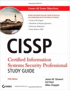
The OSI model divides networking tasks into seven distinct layers. Each layer is responsible for performing specific tasks or operations for the ultimate goal of supporting data exchange (in other words, network communication) between two computers. The layers are always numbered from bottom to top (see Figure 3.1). They are referred to by either their name or their layer number. For example, layer 3 is also known as the Network layer. The layers are ordered specifically to indicate how information flows through the various levels of communication. Each layer communicates directly with the layer above it as well as the layer below it, plus the peer layer on a communication partner system.
FIGURE 3.1 A representation of the OSI model
The OSI model is an open network architecture guide for network product vendors. This standard, or guide, provides a common foundation for the development of new protocols, networking services, and even hardware devices. By working from the OSI model, vendors are able to ensure that their products will integrate with products from other companies and be supported by a wide range of operating systems. If all vendors developed their own networking framework, interoperability between products from different vendors would be next to impossible.
The real benefit of the OSI model is its expression of how networking actually functions. In the most basic sense, network communications occur over a physical connection (whether that physical connection is electrons over copper, photons over fiber, or radio signals through the air). Physical devices establish channels through which electronic signals can pass from one computer to another. These physical device channels are only one type of the seven logical communication types defined by the OSI model. Each layer of the OSI model communicates via a logical channel with its peer layer on another computer. This enables protocols based on the OSI model to support a type of authentication by being able to identify the remote communication entity as well as authenticate the source of the received data.
Encapsulation/Deencapsulation
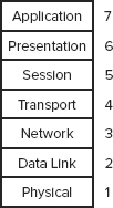
Protocols based on the OSI model employ a mechanism called encapsulation. Encapsulation is the addition of a header, and possibly a footer, to the data received by each layer from the layer above before it’s handed off the data to the layer below. As the message is encapsulated at each layer, the previous layer’s header and payload become the payload of the current layer. Encapsulation occurs as the data moves down through the OSI model layers from Application to Physical. The inverse action occurring as data moves up through the OSI model layers from Physical to Application is known as deencapsulation. The encapsulation/deencapsulation process is as follows:
1. The Application layer creates a message.
2. The Application layer passes the message to the Presentation layer.
3. The Presentation layer encapsulates the message by adding information to it. Information is usually added only at the beginning of the message (called a header); however, some layers also add material at the end of the message (called a footer), as shown in Figure 3.2.
4. The process of passing the message down and adding layer-specific information continues until the message reaches the Physical layer.
5. At the Physical layer, the message is converted into electrical impulses that represent bits and is transmitted over the physical connection.
6. The receiving computer captures the bits from the physical connection and re-creates the message in the Physical layer.
7. The Physical layer converts the message from bits into a Data Link frame and sends the message up to the Data Link layer.
8. The Data Link layer strips its information and sends the message up to the Network layer.
9. This process of deencapsulation is performed until the message reaches the Application layer.
10. When the message reaches the Application layer, the data in the message is sent to the intended software recipient.
FIGURE 3.2 A representation of OSI model encapsulation
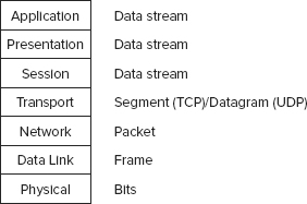
The information removed by each layer contains instructions, checksums, and so on that can be understood only by the peer layer that originally added or created the information (see Figure 3.3). This information is what creates the logical channel that enables peer layers on different computers to communicate.
FIGURE 3.3 A representation of the OSI model peer layer logical channels

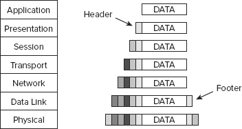
The message sent into the protocol stack at the Application layer (layer 7) is called the data stream. It retains the label of data stream until it reaches the Transport layer (layer 4), where it is called a segment (TCP protocols) or a datagram (UDP protocols). In the Network layer (layer 3), it is called a packet. In the Data Link layer (layer 2), it is called a frame. In the Physical layer (layer 1), the data has been converted into bits for transmission over the physical connection medium. Figure 3.4 shows how each layer changes the data through this process.
FIGURE 3.4 The OSI model data names
OSI Layers
Understanding the functions and responsibilities of each layer of the OSI model will help you understand how network communications function, how attacks can be perpetrated against network communications, and how security can be implemented to protect network communications. We discuss each layer, starting with the bottom layer, in the following sections.
![]()
For more information on the TCP/IP stack, search for TCP/IP at Wikipedia (http://en.wikipedia.org).
![]()
Remember the OSI
Although it can be argued that the OSI has little practical use and that most technical workers don’t use the OSI on a regular basis, you can rest assured that the OSI model and its related concepts are firmly positioned within the CISSP exam. To make the most of the OSI, you must first be able to remember the names of the seven layers in their proper order. One common method of memorizing them is to create a mnemonic from the initial letters of the layer names so they are easier to remember. One of our favorites is Please Do Not Teach Surly People Acronyms. Do take note that this memorization mnemonic works from the Physical layer up to the Application layer. A mnemonic working from the Application layer down is All Presidents Since Truman Never Did Pot. There are many others of these memorization schemes out there; just be sure you know whether they are top-down or bottom-up.
Physical Layer
The Physical layer (layer 1) accepts the frame from the Data Link layer and converts the frame into bits for transmission over the physical connection medium. The Physical layer is also responsible for receiving bits from the physical connection medium and converting them into a frame to be used by the Data Link layer.
The Physical layer contains the device drivers that tell the protocol how to employ the hardware for the transmission and reception of bits. Located within the Physical layer are electrical specifications, protocols, and interface standards such as the following:
- EIA/TIA-232 and EIA/TIA-449
- X.21
- High-Speed Serial Interface (HSSI)
- Synchronous Optical Network (SONET)
- V.24 and V.35
Through the device drivers and these standards, the Physical layer controls throughput rates, handles synchronization, manages line noise and medium access, and determines whether to use digital or analog signals or light pulses to transmit or receive data over the physical hardware interface.
Network hardware devices that function at layer 1, the Physical layer, are network interface cards (NICs), hubs, repeaters, concentrators, and amplifiers. These devices perform hardware-based signal operations, such as sending a signal from one connection port out on all other ports (a hub) or amplifying the signal to support greater transmission distances (a repeater).
Data Link Layer
The Data Link layer (layer 2) is responsible for formatting the packet from the Network layer into the proper format for transmission. The proper format is determined by the hardware and the technology of the network. There are numerous possibilities, such as Ethernet (IEEE 802.3), Token Ring (IEEE 802.5), asynchronous transfer mode (ATM), Fiber Distributed Data Interface (FDDI), and Copper DDI (CDDI). Within the Data Link layer resides the technology-specific protocols that convert the packet into a properly formatted frame. Once the frame is formatted, it is sent to the Physical layer for transmission.
The following list includes some of the protocols found within the Data Link layer:
- Serial Line Internet Protocol (SLIP)
- Point-to-Point Protocol (PPP)
- Address Resolution Protocol (ARP)
- Reverse Address Resolution Protocol (RARP)
- Layer 2 Forwarding (L2F)
- Layer 2 Tunneling Protocol (L2TP)
- Point-to-Point Tunneling Protocol (PPTP)
- Integrated Services Digital Network (ISDN)
Part of the processing performed on the data within the Data Link layer includes adding the hardware source and destination addresses to the frame. The hardware address is the Media Access Control (MAC) address, which is a 6-byte (48-bit) binary address written in hexadecimal notation (for example, 00-13-02-1F-58-F5). The first 3 bytes (24 bits) of the address denotes the vendor or manufacturer of the physical network interface. This is known as the Organizationally Unique Identifier (OUI). OUIs are registered with IEEE, who controls their issuance. The OUI can be used to discover the manufacture of a NIC through the IEEE website at http://standards.ieee.org/regauth/oui/index.shtml. The last 3 bytes (24 bits) represent a unique number assigned to that interface by the manufacturer. No two devices can have the same MAC address.
Among the protocols at the Data Link layer (layer 2) of the OSI model, the two you should be familiar with are Address Resolution Protocol (ARP) and Reverse Address Resolution Protocol (RARP). ARP is used to resolve IP addresses into MAC addresses. Traffic on a network segment (for example, cables across a hub) is directed from its source system to its destination system using MAC addresses. RARP is used to resolve MAC addresses into IP addresses.
The Data Link layer contains two sublayers: the Logical Link Control (LLC) sublayer and the MAC sublayer. Details about these sublayers are not critical for the CISSP exam.
Network hardware devices that function at layer 2, the Data Link layer, are switches and bridges. These devices support MAC-based traffic routing. Switches receive a frame on one port and send it out another port based on the destination MAC address. MAC address destinations are used to determine whether a frame is transferred over the bridge from one network to another.
Network Layer
The Network layer (layer 3) is responsible for adding routing and addressing information to the data. The Network layer accepts the segment from the Transport layer and adds information to it to create a packet. The packet includes the source and destination IP addresses.
The routing protocols are located at this layer and include the following:
- Internet Control Message Protocol (ICMP)
- Routing Information Protocol (RIP)
- Open Shortest Path First (OSPF)
- Border Gateway Protocol (BGP)
- Internet Group Management Protocol (IGMP)
- Internet Protocol (IP)
- Internet Protocol Security (IPSec)
- Internetwork Packet Exchange (IPX)
- Network Address Translation (NAT)
- Simple Key Management for Internet Protocols (SKIP)
The Network layer is responsible for providing routing or delivery information, but it is not responsible for verifying guaranteed delivery (that is the responsibility of the Transport layer). The Network layer also manages error detection and node data traffic (in other words, traffic control).
Routers and brouters are among the network hardware devices that function at layer 3. Routers determine the best logical path for the transmission of packets based on speed, hops, preference, and so on. Routers use the destination IP address to guide the transmission of packets. A brouter, working primarily in layer 3 but in layer 2 when necessary, is a device that attempts to route first, but if that fails, it defaults to bridging.
Routing Protocols
There are two broad categories of routing protocols: distance vector and link state. Distance vector routing protocols maintain a list of destination networks along with metrics of direction and distance as measured in hops (in other words, the number of routers to cross to reach the destination). Link state routing protocols maintain a topography map of all connected networks and use this map to determine the shortest path to the destination. Common examples of distance vector routing protocols are RIP, IGRP, and BGP, while a common example of a link state routing protocol is OSPF.
Transport Layer
The Transport layer (layer 4) is responsible for managing the integrity of a connection and controlling the session. It accepts a PDU from the Session layer and converts it into a segment. The Transport layer controls how devices on the network are addressed or referenced, establishes communication connections between nodes (also known as devices), and defines the rules of a session. Session rules specify how much data each segment can contain, how to verify the integrity of data transmitted, and how to determine whether data has been lost. Session rules are established through a handshaking process. (You should recall the discussion of the SYN/ACK three-way handshake for TCP/IP from Chapter 2, “Attacks and Monitoring.”)
The Transport layer establishes a logical connection between two devices and provides end-to-end transport services to ensure data delivery. This layer includes mechanisms for segmentation, sequencing, error checking, controlling the flow of data, error correction, multiplexing, and network service optimization. The following protocols operate within the Transport layer:
- Transmission Control Protocol (TCP)
- User Datagram Protocol (UDP)
- Sequenced Packet Exchange (SPX)
- Secure Sockets Layer (SSL)
- Transport Layer Security (TLS)
Session Layer
The Session layer (layer 5) is responsible for establishing, maintaining, and terminating communication sessions between two computers. It manages dialogue discipline or dialogue control (simplex, half-duplex, full-duplex), establishes checkpoints for grouping and recovery, and retransmits PDUs that have failed or been lost since the last verified checkpoint. The following protocols operate within the Session layer:
- Network File System (NFS)
- Structured Query Language (SQL)
- Remote Procedure Call (RPC)
Communication sessions can operate in one of three different discipline or control modes:
Simplex One-way direction communication
Half-duplex Two-way communication, but only one direction can send data at a time
Full-duplex Two-way communication, in which data can be sent in both directions simultaneously
Presentation Layer
The Presentation layer (layer 6) is responsible for transforming data received from the Application layer into a format that any system following the OSI model can understand. It imposes common or standardized structure and formatting rules onto the data. The Presentation layer is also responsible for encryption and compression. Thus, it acts as an interface between the network and applications. It is what allows various applications to interact over a network, and it does so by ensuring that the data formats are supported by both systems. Most file or data formats operate within this layer. This includes formats for images, video, sound, documents, email, web pages, control sessions, and so on. The following list includes some of the format standards that exist within the Presentation layer:
- American Standard Code for Information Interchange (ASCII)
- Extended Binary-Coded Decimal Interchange Mode (EBCDIC)
- Tagged Image File Format (TIFF)
- Joint Photographic Experts Group (JPEG)
- Moving Picture Experts Group (MPEG)
- Musical Instrument Digital Interface (MIDI)
![]()
So Many Protocols, So Many Layers
With seven layers and more than 50 protocols, it may seem daunting to remember the layer in which each protocol resides. One way to learn this is to create flash cards. On the front of each card, write the name of the protocol; then on the back, write the layer name. After shuffling the cards, put each protocol in a pile representing its supposed layer. Once you have placed all the protocols, check your work by viewing the backs of the cards. Repeat this process until you are able to place each one correctly.
Application Layer
The Application layer (layer 7) is responsible for interfacing user applications, network services, or the operating system with the protocol stack. It allows applications to communicate with the protocol stack. The Application layer determines whether a remote communication partner is available and accessible. It also ensures that sufficient resources are available to support the requested communications.
The application is not located within this layer; rather, the protocols and services required to transmit files, exchange messages, connect to remote terminals, and so on are found here. Numerous application-specific protocols are found within this layer, such as the following:
- Hypertext Transfer Protocol (HTTP)
- File Transfer Protocol (FTP)
- Line Print Daemon (LPD)
- Simple Mail Transfer Protocol (SMTP)
- Telnet
- Trivial File Transfer Protocol (TFTP)
- Electronic Data Interchange (EDI)
- Post Office Protocol version 3 (POP3)
- Internet Message Access Protocol (IMAP)
- Simple Network Management Protocol (SNMP)
- Network News Transport Protocol (NNTP)
- Secure Remote Procedure Call (S-RPC)
- Secure Electronic Transaction (SET)
There is a network device (or service) that works at the Application layer, namely, the gateway. However, an Application layer gateway is a specific type of component. It serves as a protocol translation tool. For example, an IP-to-IPX gateway takes inbound communications from TCP/IP and translates them over to IPX/SPX for outbound transmission.
TCP/IP Model
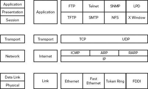
The TCP/IP model (also called the DARPA or the DOD model) consists of only four layers, as opposed to the OSI Reference Model’s seven. The four layers of the TCP/IP model are Application, Transport (previously known as Host-to-Host), Internet (sometimes Internetworking), and Link (although Network Interface and sometimes Network Access are used). Figure 3.5 shows how they compare to the seven layers of the OSI model. The TCP/IP protocol suite was developed before the OSI Reference Model was created. The designers of the OSI Reference Model took care to ensure that the TCP/IP protocol suite fit their model because of its established deployment in networking.
FIGURE 3.5 Comparing the OSI model with the TCP/IP model
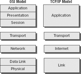
The TCP/IP model’s Application layer corresponds to layers 5, 6, and 7 of the OSI model. The TCP/IP model’s Transport layer corresponds to layer 4 from the OSI model. The TCP/IP model’s Internet layer corresponds to layer 3 from the OSI model. The TCP/IP model’s Link layer corresponds to layers 1 and 2 from the OSI model.
It has become common practice (through confusion, misunderstanding, and probably laziness) to also call the TCP/IP model layers by their OSI model layer equivalent names. The TCP/IP model’s Application layer is already using a name borrowed from the OSI, so that one is a snap. The TCP/IP model’s Host-to-Host layer is sometimes called the Transport layer (the OSI model’s fourth layer). The TCP/IP model’s Internet layer is sometimes called the Network layer (the OSI model’s third layer). And the TCP/IP model’s Link layer is sometimes called the Data Link or the Network Access layer (the OSI model’s second layer).
![]()
Since the TCP/IP model layer names and the OSI model layer names can be used interchangeably, it is important to know which model is being addressed in various contexts. Unless informed otherwise, always assume the OSI model provides the basis for discussion because it’s the most widely used network reference model.
Communications and Network Security
Establishing security on a network involves more than just managing the operating system and software. You must also address physical issues, including cabling, topology, and technology.
LANs vs. WANs
There are two basic types of networks: LANs and WANs. A local area network (LAN) is a network typically spanning a single floor or building. This is commonly a limited geographical area. Wide area network (WAN) is the term usually assigned to the long-distance connections between geographically remote networks.
WAN connections and communication links can include private circuit technologies and packet-switching technologies. Common private circuit technologies include dedicated or leased lines and PPP, SLIP, ISDN, and DSL connections. Packet-switching technologies include X.25, Frame Relay, asynchronous transfer mode (ATM), Synchronous Data Link Control (SDLC), and High-Level Data Link Control (HDLC). Packet-switching technologies use virtual circuits instead of dedicated physical circuits. A virtual circuit is created only when needed, which makes for efficient use of the transmission medium and is extremely cost-effective. (We discuss the WAN technologies in Chapter 4.)
Network Cabling
The type of connectivity media employed in a network is important to the network’s design, layout, and capabilities. Without the right cabling or transmission media, a network may not be able to span your entire enterprise, or it may not support the necessary traffic volume. In fact, the most common causes of network failure (in other words, violations of availability) are caused by cable failures or misconfigurations. It is important for you to understand that different types of network devices and technologies are used with different types of cabling. Each cable type has unique useful lengths, throughput rates, and connectivity requirements.
Coaxial Cable
Coaxial cable, also called coax, was a popular networking cable type used throughout the 1970s and 1980s. In the early 1990s, its use quickly declined because of the popularity and capabilities of twisted-pair wiring (explained in more detail later). Coaxial cable has a center core of copper wire surrounded by a layer of insulation, which is in turn surrounded by a conductive braided shielding and encased in a final insulation sheath.
The center copper core and the braided shielding layer act as two independent conductors, thus allowing two-way communications over a coaxial cable. The design of coaxial cable makes it fairly resistant to electromagnetic interference (EMI) and makes it able to support high bandwidths (in comparison to other technologies of the time period), and it offers longer usable lengths than twisted-pair. It ultimately failed to retain its place as the popular networking cable technology because of twisted-pair’s much lower cost and ease of installation. Coaxial cable requires the use of segment terminators, whereas twisted-pair cabling does not. Coaxial cable is bulkier and has a larger minimum arc radius than twisted-pair. (The arc radius is the maximum distance the cable can be bent before damaging the internal conductors.) Additionally, with the widespread deployment of switched networks, the issues of cable distance became moot because of the implementation of hierarchical wiring patterns.
There are two main types of coaxial cable: thinnet and thicknet. Thinnet, also known as 10Base2, was commonly used to connect systems to backbone trunks of thicknet cabling. Thinnet can span distances of 185 meters and provide throughput up to 10 Mbps. Thicknet, also known as 10Base5, can span 500 meters and provide throughput up to 10 Mbps.
The most common problems with coax cable are as follows:
- Bending the coax cable past its minimum arc radius and thus breaking the center conductor
- Deploying the coax cable in a length greater than its maximum recommended length (which is 185 meters for 10Base2 or 500 meters for 10Base5)
- Not properly terminating the ends of the coax cable with a 50 ohm resistor
Baseband and Broadband
The naming convention used to label most network cable technologies follows the syntax XXyyyyZZ. XX represents the maximum speed the cable type offers, such as 10 Mbps for a 10Base2 cable. The next series of letters, yyyy, represents the baseband or broadband aspect of the cable, such as baseband for a 10Base2 cable. Baseband cables can transmit only a single signal at a time, and broadband cables can transmit multiple signals simultaneously. Most networking cables are baseband cables. However, when used in specific configurations, coaxial cable can be used as a broadband connection, such as with cable modems. ZZ either represents the maximum distance the cable can be used or acts as shorthand to represent the technology of the cable, such as the approximately 200 meters for 10Base2 cable (actually 185 meters, but it’s rounded up to 200) or T or TX for twisted-pair in 10Base-T or 100Base-TX. (Note that 100Base-TX is implemented using two CAT 5 UTP or STP cables—one issued for receiving, the other for transmitting.)
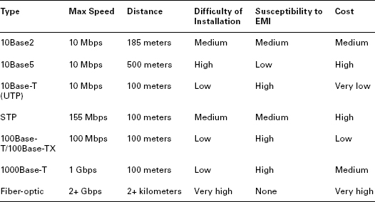
TABLE 3.1 shows the important characteristics for the most common network cabling types.
Table 3.1 Important characteristics for common network cabling typesa
Twisted-Pair
Twisted-pair cabling is extremely thin and flexible compared to coaxial cable. It consists of four pairs of wires that are twisted around each other and then sheathed in a PVC insulator. If there is a metal foil wrapper around the wires underneath the external sheath, the wire is known as shielded twisted-pair (STP). The foil provides additional protection from external EMI. Twisted-pair cabling without the foil is known as unshielded twisted-pair (UTP). UTP is most often referred to as just 10Base-T.
The wires that make up UTP and STP are small, thin copper wires that are twisted in pairs. The twisting of the wires provides protection from external radio frequencies and electric and magnetic interference and reduces crosstalk between pairs. Crosstalk occurs when data transmitted over one set of wires is picked up by another set of wires due to radiating electromagnetic fields produced by the electrical current. Each wire pair within the cable is twisted at a different rate (in other words, twists per inch); thus, the signals traveling over one pair of wires cannot cross over onto another pair of wires (at least within the same cable). The tighter the twist (the more twists per inch), the more resistant the cable is to internal and external interference and crosstalk, and thus the capacity for throughput (that is, higher bandwidth) is greater.
There are several classes of UTP cabling. The various categories are created through the use of tighter twists of the wire pairs, variations in the quality of the conductor, and variations in the quality of the external shielding. TABLE 3.2 shows the UTP categories.
Table 3.2 UTP categories
| UTP Category | Throughput | Notes |
| Cat 1 | Voice only | Not suitable for networks, but usable by modems |
| Cat 2 | 4 Mbps | Not suitable for most networks; often employed for host-to-terminal connections on mainframes |
| Cat 3 | 10 Mbps | Primarily used in 10Base-T Ethernet networks (offers only 4 Mpbs when used on Token Ring networks) |
| Cat 4 | 16 Mbps | Primarily used in Token Ring networks |
| Cat 5 | 100 Mbps | Used in 100Base-TX, FDDI, and ATM networks |
| Cat 6 | 155 Mbps | Used in high-speed networks |
| Cat 7 | 1 Gbps | Used on gigabit-speed networks |
![]()
Cat 5e is an enhanced version of Cat 5 designed to protect against far-end crosstalk. In 2001, the TIA/EIA-568-B no longer recognized the original Cat 5 specification. Now, the Cat 5e standard is rated for use by 100Base-T and even 1000Base-T deployments.
The following problems are the most common with twisted-pair cabling:
- Using the wrong category of twisted-pair cable for high-throughput networking
- Deploying a twisted-pair cable longer than its maximum recommended length (in other words, 100 meters)
- Using UTP in environments with significant interference
Conductors
The distance limitations of conductor-based network cabling stem from the resistance of the metal used as a conductor. Copper, the most popular conductor, is one of the best and least expensive room-temperature conductors available. However, it is still resistant to the flow of electrons. This resistance results in a degradation of signal strength and quality over the length of the cable.
![]()
Plenum cable is a type of cabling sheathed with a special material that does not release toxic fumes when burned, as does traditional PVC coated wiring. Often plenum-grade cable must be used to comply with building codes, especially if the building has enclosed spaces that could trap gases.
The maximum length defined for each cable type indicates the point at which the level of degradation could begin to interfere with the efficient transmission of data. This degradation of the signal is known as attenuation. It is often possible to use a cable segment that is longer than the cable is rated for, but the number of errors and retransmissions will be increased over that cable segment, ultimately resulting in poor network performance. Attenuation is more pronounced as the speed of the transmission increases. It is recommended that you use shorter cable lengths as the speed of the transmission increases.
Long cable lengths can often be supplemented through the use of repeaters or concentrators. A repeater is a signal amplification device, much like the amplifier for your car or home stereo. The repeater boosts the signal strength of an incoming data stream and rebroadcasts it through its second port. A concentrator does the same thing except it has more than two ports. However, using more than four repeaters in a row is discouraged (see the sidebar “5-4-3 Rule”).
5-4-3 Rule
The 5-4-3 rule is used whenever Ethernet or other IEEE 802.3 shared-access networks are deployed in a tree topology (in other words, a central trunk with various splitting branches). This rule defines the number of repeaters/concentrators and segments that can be used in a network design. The rule states that between any two nodes (a node can be any type of processing entity, such as a server, client, or router), there can be a maximum of five segments connected by four repeaters/concentrators, and it states that only three of those five segments can be populated (in other words, have additional or other user, server, or networking device connections).
The 5-4-3 rule does not apply to switched networks or the use of bridges or routers.
An alternative to conductor-based network cabling is fiber-optic cable. Fiber-optic cables transmit pulses of light rather than electricity. This has the advantage of being extremely fast and nearly impervious to tapping and interference. However, it is difficult to install and expensive; thus, the security and performance it offers comes at a steep price.
Wireless Communications and Security
Wireless communications is a quickly expanding field of technologies for networking, connectivity, communication, and data exchange. There are literally thousands of protocols, standards, and techniques that can be labeled as wireless. These include cell phones, Bluetooth, cordless phones, and wireless networking. As wireless technologies continue to proliferate, your organization’s security must go beyond locking down its local network. Security should be an end-to-end solution that addresses all forms, methods, and techniques of communication.
General Wireless Concepts
Wireless communications employ radio waves to transmit signals over a distance. There is a finite amount of radio wave spectrum; thus, its use must be managed properly to allow multiple simultaneous uses with little to no interference. The radio spectrum is measured or differentiated using frequency. Frequency is a measurement of the number of wave oscillations within a specific time identified using the unit Hertz (Hz), or oscillations per second. Radio waves have a frequency between 3 Hz and 300 GHz. Different ranges of frequencies have been designated for specific uses, such as AM and FM radio, VHF and UHF television, and so on. Currently, the 900 MHz, 2.4 GHz, and 5 GHz frequencies are the most commonly used in wireless products because of their unlicensed categorization. However, to manage the simultaneous use of the limited radio frequencies, several spectrum-use techniques were developed. This included spread spectrum, FHSS, DSSS, and OFDM.
![]()
Most devices operate within a small subsection of frequencies rather than all available frequencies. This is because of frequency-use regulations (in other words, the FCC in the United States), power consumption, and the expectation of interference.
Spread spectrum means that communication occurs over multiples frequencies at the same time. Thus, a message is broken into pieces, and each piece is sent at the same time but using a different frequency. Effectively this is a parallel communication rather than a serial communication.
Frequency Hopping Spread Spectrum (FHSS) was an early implementation of the spread spectrum concept. However, instead of sending data in a parallel fashion, it transmits data in a series while constantly changing the frequency in use. The entire range of available frequencies is employed, but only one frequency at a time is used. As the sender changes from one frequency to the next, the receiver has to follow the same hopping pattern to pick up the signal. FHSS was designed to help minimize interference by not using only a single frequency that could be affected. Instead, by constantly shifting frequencies, it minimizes interference.
Direct Sequence Spread Spectrum (DSSS) employs all the available frequencies simultaneously in parallel. This provides a higher rate of data throughput than FHSS. DSSS also uses a special encoding mechanism known as chipping code to allow a receiver to reconstruct data even if parts of the signal were distorted because of interference. This occurs in much the same way that the parity of RAID 5 allows the data on a missing drive to be re-created.
Orthogonal Frequency-Division Multiplexing (OFDM) is yet another variation on frequency use. OFDM employs a digital multicarrier modulation scheme that allows for a more tightly compacted transmission. The modulated signals are perpendicular (orthogonal) and thus do not cause interference with each other. Ultimately, OFDM requires a smaller frequency set (aka channel bands) but can offer greater data throughput.
Cell Phones
Cell phone wireless communications consist of using a portable device over a specific set of radio wave frequencies to interact with the cell phone carrier’s network and either other cell phone devices or the Internet. The technologies used by cell phone providers are numerous and are often confusing. One point of confusion is the use of terms like 2G and 3G. These do not refer to technologies specifically but instead to the generation of cell phone technology. Thus, 1G is the first generation (mostly analog), 2G is the second (mostly digital, as are 3G and 4G), and so forth. There are even discussions of 2.5G when systems integrate second- and third-generation technologies. TABLE 3.3 attempts to clarify some of these confusing issues (this is only a partial listing of the technologies).
Table 3.3 Some wireless telephone technologies
| Technology | Generation |
| NMT | 1G |
| AMPS | 1G |
| TACS | 1G |
| GSM | 2G |
| iDEN | 2G |
| TDMA | 2G |
| CDMA | 2G |
| PDC | 2G |
| HSCSD | 2.5G |
| GPRS | 2.5G |
| W-CDMA | 3G |
| TD-CDMA | 3G |
| UWC | 3G |
| EDGE | 3G |
| DECT | 3G |
| UMTS | 3G |
| HSPDA | 3.5G |
| WINNER | 4G |
| WWRF | 4G |
| WiMax – IEEE 802.16 | 4G |
| XOHM | 4G |
| Mobile Broadband – IEEE 801.20 | 4G |
| LTE (Long Term Evolution) | 4G |
There are a few key issues to keep in mind with regard to cell phone wireless transmissions. First, not all cell phone traffic is voice; often cell phone systems are used to transmit text and even computer data. Second, communications over a cell phone provider’s network, whether voice, text, or data, are not necessarily secure. Third, with specific wireless-sniffing equipment, your cell phone transmissions can be intercepted. Fourth, using your cell phone connectivity to access the Internet or your office network provides attackers with yet another potential avenue of attack, access, and compromise.
One important cell phone technology to discuss is Wireless Application Protocol (WAP). WAP is often confused with wireless networking (802.11). This is due to the use of the same acronym, which stands for Wireless Access Point when used in relation to 802.11. However, it is different in that with WAP, portable devices use a cell phone carrier’s network to establish communication links with the Internet, while with wireless networking, an organization deploys its own wireless access points to allow its wireless clients to connect to its local network. WAP is not a standard; instead, it is a functioning industry-driven protocol stack. Via WAP-capable devices, users can communicate with the company network by connecting from their cell phone or PDA through the cell phone carrier network over the Internet and through a gateway into the company network. WAP is a suite of protocols working together. One of these protocols is Wireless Transport Layer Security (WTLS), which provides security connectivity services similar to those of SSL or TLS.
One very important security issue to recognize with WAP or with any security service provided by a telco is that you are unlikely to obtain true end-to-end protection from a communications service provider. The U.S. law known as the Communications Assistance for Law Enforcement Act (CALEA) mandates that all telcos, regardless of the technologies involved, must make it possible to wiretap voice and data communications when a search warrant is presented. Thus, a telco cannot provide customers with end-to-end encryption. At some point along the communication path, the data must be returned to clear form before being resecured for the remainder of the journey to its destination. WAP complies with the CALEA restriction as follows: A secure link is established between the mobile device and the telco’s main server using WAP/WTLS. The data is converted into its clear form before being reencapsulated in SSL, TLS, IPSec, and so on for its continued transmission to its intended destination. Knowing this, use telco services appropriately, and whenever possible, feed pre-encrypted data into the telco link rather than clear form data.
Bluetooth (802.15)
Bluetooth or IEEE 802.15 personal area networks (PANs) are another area of wireless security concern. Headsets for cell phones, mice, keyboards, GPS devices, and many other interface devices and peripherals are being connected via Bluetooth. Many of these connections are set up using a technique known as pairing, where the primary device scans the 2.4 GHz radio frequencies for available devices, and then, once a device is discovered, a four-digit PIN is used to “authorize” the pairing. This process does reduce the number of accidental pairings; however, a four-digit PIN is not secure (not to mention that the default PIN is often 0000). In addition, there are attacks against Bluetooth-enabled devices. One technique, known as bluejacking, is able to transmit SMS-like messages to your device. Bluesnarfing allows hackers to connect with your Bluetooth devices without your knowledge and extract information from them. This form of attack can offer attackers access to your contact lists, your data, and even your conversations. Bluebugging is an attack that grants hackers remote control over the feature and functions of a Bluetooth device. This could include the ability to turn on the microphone to use the phone as an audio bug. Fortunately, Bluetooth typically has a limited range of 30 feet, but some devices can function from more than 100 meters away. Bluetooth devices sometimes employ encryption, but it is not dynamic and can be usually cracked with modest effort. Use Bluetooth for those activities that are not sensitive or confidential. Whenever possible, change the default PINs on your devices. Do not leave your devices in discovery mode, and always turn off Bluetooth when not in active use.
Cordless Phones
Cordless phones represent an often-overlooked security issue. Cordless phones are designed to use any one of the unlicensed frequencies, in other words, 900 MHz, 2.4 GHz, or 5 GHz. These three unlicensed frequency ranges are employed by many different types of devices, from cordless phones and baby monitors to Bluetooth and wireless networking devices. The issue that is often overlooked is that someone could easily eavesdrop on a conversation on a cordless phone since its signal is rarely encrypted. With a frequency scanner, anyone can listen in on your conversations.
Wireless Networking (802.11)
Wireless networking is a popular method of connecting systems for communications because of the ease of deployment and relatively low cost. Historically, wireless networking has been fairly insecure, mainly because of a lack of knowledge by end users and organizations as well as insecure default configurations set by device manufacturers.
Wireless networking is primarily based on the IEEE 802.11 standard. It uses two primary components: an access point and host interfaces. The access point or wireless access point is the radio signal hub for the wireless network. The wireless access point supports associations with host devices with wireless interfaces (wireless NICs). The wireless access point performs a proxy function of converting the radio signal transmissions into cable-based transmissions in order to support communications between the wireless clients and the wired network and often ultimately the Internet.
Wireless networks can be deployed in two primary methods: ad hoc and infrastructure. An ad hoc, or peer-to-peer, network links wireless clients directly without the use of a wireless access point. Infrastructure mode is any wireless network configuration using a wireless access point to connect wireless clients. Within the infrastructure mode concept are several variations, including stand-alone, wired extension, enterprise extended, and bridge. A stand-alone mode infrastructure occurs when there is a wireless access point connecting wireless clients to each other, but not to any wired resources. The wireless access point serves as a wireless hub exclusively. A wired extension mode infrastructure occurs when the wireless access point acts as a connection point to link the wireless clients to the wired network. An enterprise extended mode infrastructure occurs when multiple wireless access points (WAPs) are used to connect a large physical area to the same wired network. Each wireless access point will use the same Extended Service Set Identifier (ESSID) so clients can roam the area while maintaining network connectivity, even while their wireless NICs change associations from one wireless access point to another. A bridge mode infrastructure occurs when a wireless connection is used to link two wired networks. This often uses dedicated wireless bridges and is used when wired bridges are inconvenient, such as when linking networks between floors or buildings.
![]()
The term SSID (which stands for service set identifier) is typically misused to indicate the name of a wireless network. Technically there are two types of SSIDs, namely extended service set identifier (ESSID) and basic service set identifier (BSSID). An ESSID is the name of a wireless network when a wireless base station or WAP is used (i.e., infrastructure mode). A BSSID is the name of a wireless network when in ad-hoc or peer-to-peer mode (i.e., when a base station or WAP is not used). However, when operating in infrastructure mode, the BSSID is the MAC address of the base station hosting the ESSID in order to differentiate multiple base stations supporting a single extended wireless network.
![]()
Wireless Channels
There are so many more topics within wireless networking that we are not addressing because of space limitations and because they’re not covered on the exam. For instance, you may want to learn more about wireless channels. Within the assigned frequency of the wireless signal are subdivisions of that frequency known as channels. Think of channels as lanes on the same highway. In the United States, there are 11 channels, in Europe there are 13, and in Japan there are 17. The differences stem from local laws regarding frequency management (think international versions of the United States’s FCC). Wireless communications take place between a client and access point over a single channel. However, when two or more access points are relatively close to each other physically, signals on one channel can interfere with signals on another channel. One way to avoid this is to set the channels of physically close access points as differently as possible to minimize channel overlap interference. For example, if a building has four access points arranged in a line along the length of the building, the channel settings could be 1, 11, 1, and 11. However, if the building is square and an access point is in each corner, the channel settings may need to be 1, 4, 8, and 11. Think of the signal within a single channel as like a wide-load truck in a lane on the highway. The wide-load truck is using part of each lane to either side of it, thus making passing the truck in those lanes dangerous. Likewise, wireless signals in adjacent channels will interfere with each other.
Wireless networks are assigned a service set identifier (SSID) (either BSSID or ESSID) to differentiate one wireless network from another. If multiple basestations or wireless access points are involved in the same wireless network, an extended station set identifier (ESSID) is defined. The SSID is similar to the name of a workgroup. If a wireless client knows the SSID, they can configure their wireless NIC to communicate with the associated WAP. Knowledge of the SSID does not always grant entry, though, because the WAP can use numerous security features to block unwanted access. SSIDs are defined by default by vendors, and since these default SSIDs are well known, standard security practice dictates that the SSID should be changed to something unique before deployment. The SSID is broadcast by the WAP via a special transmission called a beacon frame. This allows any wireless NIC within range to see the wireless network and make connecting as simple as possible. However, this default broadcasting of the SSID should be disabled to keep the wireless network secret. However, attackers can still discover the SSID with a wireless sniffer since the SSID must still be used in transmissions between wireless clients and the WAP. Thus, disabling SSID broadcasting is not a true mechanism of security. Instead, use WPA2 as a reliable authentication and encryption solution rather than trying to hide the existence of the wireless network.
The IEEE 802.11 standard defines two methods that wireless clients can use to authenticate to WAPs before normal network communications can occur across the wireless link. These two methods are open system authentication (OSA) and shared key authentication (SKA). OSA means there is no real authentication required. As long as a radio signal can be transmitted between the client and WAP, communications are allowed. It is also the case that wireless networks using OSA typically transmit everything in clear text, thus providing no secrecy or security. SKA means that some form of authentication must take place before network communications can occur. The 802.11 standard defines one optional technique for SKA known as Wired Equivalent Privacy (WEP).
WEP is a form of encrypted authentication that employs RC4. WEP supports only one-way authentication from client to WAP. WEP is considered insufficient for security because of several deficiencies in its design and implementation. WEP uses static keys, uses initialization vectors improperly, and does not maintain true packet integrity. Because of these factors, attackers have developed techniques to crack WEP in less than a minute. Therefore, WEP should be used only when no other more secure option is available. Fortunately, WEP is optional, and the 802.11 standard allows for add-on security and authentication features.
An early alternative to WEP was WiFi Protected Access (WPA). This technique was an improvement but was itself not fully secure. It is based on the LEAP and TKIP cryptosystem and employs a secret passphrase. Unfortunately, the use of a single static passphrase is the downfall of WPA. An attacker can simply run a brute-force guessing attack against a WPA network to discover the base passphrase. If the passphrase is 14 characters or more, this is usually a time-prohibitive proposition, but not an impossible one. Additionally, both the LEAP and TKIP encryption options for WPA are now crackable using a variety of cracking techniques. While it is more complex than a WEP compromise, WPA no longer provides long-term reliable security.
Eventually, two new methods were developed that are still considered secure. First is the amendment known as 802.11i or WPA-2. It is a new encryption scheme known as the Counter Mode with Cipher Block Chaining Message Authentication Code Protocol (CCMP), which uses the AES encryption scheme. To date, no real-world attack has compromised the encryption of a properly configured WPA-2 wireless network. The second method is the use of 802.1X, a standard port-based network access control that ensures that clients cannot communicate with a resource until proper authentication has taken place. Effectively, 802.1X is a hand-off system that allows the wireless network to leverage the existing network infrastructure’s authentication services. Through the use of 802.1X, other techniques and solutions such as RADIUS, TACACS, certificates, smart cards, token devices, and biometrics can be integrated into wireless networks.
Even though wireless networks are often inexpensive to initially deploy, some organizations have decided that the long-term cost to maintain and secure wireless is much more costly than a wired network. If a wireless network is present, you can take several steps to improve its security (these are in order of consideration and application/installation; additionally, this order does not imply security or importance priority because using WPA-2 is a real security feature as opposed to SSID broadcast disabling):
1. Change the default administrator password.
2. Disable the SSID broadcast.
3. Change the SSID to something unique.
4. Enable MAC filtering if the pool of wireless clients is relatively small (usually less than 20) and static.
5. Consider using static IP addresses, or configure DHCP with reservations (applicable only for small deployments).
6. Turn on the highest form of authentication encryption supported: WEP, WPA, or WPA-2 (802.11i).
7. Treat wireless as remote access, and manage access using 802.1X.
8. Treat wireless as external access, and separate the WAP from the wired network using a firewall.
9. Treat wireless as an entry point for attackers, and monitor all WAP-to-wired-network communications with an IDS.
10. Require all transmissions between wireless clients and WAPs to be encrypted; in other words, require a VPN link.
![]()
Often, adding data encryption and other forms of filtering to a wireless link can reduce the effective throughput as much as 80 percent.
Wireless Attacks
Even with wireless security present, wireless attacks can still occur. There is an ever-increasing variety of attacks against networks, and many of these work against both wired and wireless environments. A few focus on wireless networks alone. One of these is a collection of techniques to discover that a wireless network is present, commonly called wardriving. It basically is the use of a wireless interface or a wireless detector to locate wireless network signals. Once an attacker knows there is a wireless network present, they can use sniffers to gather wireless packets for investigation. With the right tools, an attacker can discover hidden SSIDs, active IP addresses, valid MAC addresses, and even the authentication mechanism in use by the wireless clients. From there, attackers can grab dedicated cracking tools to attempt to break into the connection. The older and weaker your protections, the faster and more successful such attacks become.
Four main 802.11 wireless network amendments define unique frequencies and speeds of transmission (among many other technical details). TABLE 3.4 lists several of these along with their speed and frequency. The b, g, and n amendments all use the same frequency; thus, they maintain backward compatibility.
Table 3.4 802.11 wireless networking amendments
| Amendment | Speed | Frequency |
| 802.11a | 54 Mbps | 5 GHz |
| 802.11b | 11 Mbps | 2.4 GHz |
| 802.11g | 54 Mbps | 2.4 GHz |
| 802.11n | 200+ Mbps | 2.4 GHz or 5 GHz |
Two final items in the realm of wireless networking are WiMax (802.16) and Mobile Broadband (802.20). These standards are designed to support broadband access over a metropolitan area, in other words, citywide wireless network connectivity. If you want more information on this topic, please visit Wikipedia or the IEEE standards page (http://standards.ieee.org/getieee802/index.html) and follow its external links.
LAN Technologies
There are three main types of LAN technologies: Ethernet, Token Ring, and FDDI. There are a handful of other LAN technologies, but they are not as widely used as these three. Plus, only these three are potentially addressed on the CISSP exam. Most of the differences between LAN technologies exist at and below the Data Link layer.
Ethernet
Ethernet is a shared-media LAN technology (also known as a broadcast technology). That means it allows numerous devices to communicate over the same medium but requires that the devices take turns communicating and perform collision detection and avoidance. Ethernet employs broadcast and collision domains. A broadcast domain is a physical grouping of systems in which all the systems in the group receive a broadcast sent by a single system in the group. A broadcast is a message transmitted to a specific address that indicates that all systems are the intended recipients.
A collision domain consists of groupings of systems within which a data collision occurs if two systems transmit simultaneously. A data collision takes place when two transmitted messages attempt to use the network medium at the same time. It causes one or both of the messages to be corrupted.
Ethernet can support full-duplex communications (in other words, full two-way) and usually employed using twisted-pair cabling (Note that coaxial cabling was the original cabling type used to support Ethernet, but coax is now a legacy cable type). Ethernet is most often deployed on star or bus topologies. Ethernet is based on the IEEE 802.3 standard. Individual units of Ethernet data are called frames. Fast Ethernet supports 100 Mbps throughput. Gigabit Ethernet supports 1000 Gbps throughput.
Token Ring
Token Ring employs a token-passing mechanism to control which systems can transmit data over the network medium. The token travels in a logical loop among all members of the LAN. Token Ring can be employed on ring or star network topologies. It is rarely used today because of its performance limitations, higher cost compared to Ethernet, and increased difficulty in deployment and management.
Token Ring can be deployed as a physical star using a multistation access unit (MAU). An MAU allows for the cable segments to be deployed as a star, while internally the device makes logical ring connections.
Fiber Distributed Data Interface (FDDI)
Fiber Distributed Data Interface (FDDI) is a high-speed token-passing technology that employs two rings with traffic flowing in opposite directions. FDDI is often used as a backbone for large enterprise networks. Its dual-ring design allows for self-healing by removing the failed segment from the loop and creating a single loop out of the remaining inner and outer ring portions. FDDI is expensive but was often used in campus environments before Fast Ethernet and Gigabit Ethernet were developed. A less-expensive, distance-limited, and slower version known as Copper Distributed Data Interface (CDDI) uses twisted-pair cables. CDDI is also more vulnerable to interference and eavesdropping.
Subtechnologies
Most networks comprise numerous technologies rather than a single technology. For example, Ethernet is not just a single technology but a superset of subtechnologies that support its common and expected activity and behavior. Ethernet includes the technologies of digital communications, synchronous communications, and baseband communications, and it supports broadcast, multicast, and unicast communications and Carrier-Sense Multiple Access with Collision Detection (CSMA/CD). Many of the LAN technologies, such as Ethernet, Token Ring, and FDDI, may include many of the subtechnologies described in the following sections.
Analog and Digital
One subtechnology common to many forms of network communications is the mechanism used to actually transmit signals over a physical medium, such as a cable. There are two types: analog and digital. Analog communications occur with a continuous signal that varies in frequency, amplitude, phase, voltage, and so on. The variances in the continuous signal produce a wave shape (as opposed to the square shape of a digital signal). The actual communication occurs by variances in the constant signal. Digital communications occur through the use of a discontinuous electrical signal and a state change or on-off pulses.
Digital signals are more reliable than analog signals over long distances or when interference is present. This is because of its definitive information storage method employing direct current voltage where voltage on represents a value of 1 and voltage off represents a value of 0. These on-off pulses create a stream of binary data. Analog signals become altered and corrupted because of attenuation over long distances and interference. Since an analog signal can have an infinite number of variations used for signal encoding as opposed to digital’s two states, unwanted alterations to the signal make extraction of the data more difficult as the degradation increases.
Synchronous and Asynchronous
Some communications are synchronized with some sort of clock or timing activity. Communications are either synchronous or asynchronous. Synchronous communications rely upon a timing or clocking mechanism based upon either an independent clock or a time stamp embedded in the data stream. Synchronous communications are typically able to support very high rates of data transfer. Asynchronous communications rely upon a stop and start delimiter bit to manage the transmission of data. Because of the use of delimiter bits and the stop and start nature of its transmission, asynchronous communication is best suited for smaller amounts of data. Public switched telephone network (PSTN) modems are good examples of asynchronous communication.
Baseband and Broadband
How many communications can occur simultaneously over a cable segment depends on whether you use baseband technology or broadband technology. Baseband technology can support only a single communication channel. It uses a direct current applied to the cable. A current that is at a higher level represents the binary signal of 1, and a current that is at a lower level represents the binary signal of 0. Baseband is a form of digital signal. Ethernet is a baseband technology.
Broadband technology can support multiple simultaneous signals. Broadband uses frequency modulation to support numerous channels, each supporting a distinct communication session. Broadband is suitable for high-throughput rates, especially when several channels are multiplexed. Broadband is a form of analog signal. Cable television and cable modems, ISDN, DSL, T1, and T3 are examples of broadband technologies.
Broadcast, Multicast, and Unicast
Another technology determines how many destinations a single transmission can reach. The options are broadcast, multicast, and unicast. A broadcast technology supports communications to all possible recipients. A multicast technology supports communications to multiple specific recipients. A unicast technology supports only a single communication to a specific recipient.
LAN Media Access
Finally, there are at least five LAN media access technologies that are used to avoid or prevent transmission collisions. These technologies define how multiple systems all within the same collision domain are to communicate. Some of these technologies actively prevent collisions, while others respond to collisions.
Carrier-Sense Multiple Access (CSMA) This is the LAN media access technology that performs communications using the following steps:
1. The host listens to the LAN media to determine whether it is in use.
2. If the LAN media is not being used, the host transmits its communication.
3. The host waits for an acknowledgment.
4. If no acknowledgment is received after a time-out period, the host starts over at step 1.
CSMA does not directly address collisions. If a collision occurs, the communication would not have been successful, and thus an acknowledgment would not be received. This causes the sending system to retransmit the data and reperform the CSMA process.
Carrier-Sense Multiple Access with Collision Avoidance (CSMA/CA) This is the LAN media access technology that performs communications using the following steps:
1. The host has two connections to the LAN media: inbound and outbound. The host listens on the inbound connection to determine whether the LAN media is in use.
2. If the LAN media is not being used, the host requests permission to transmit.
3. If permission is not granted after a time-out period, the host starts over at step 1.
4. If permission is granted, the host transmits its communication over the outbound connection.
5. The host waits for an acknowledgment.
6. If no acknowledgment is received after a time-out period, the host starts over at step 1.
AppleTalk and 802.11 wireless networking are examples of networks that employ CSMA/CA technologies. CSMA/CA attempts to avoid collisions by granting only a single permission to communicate at any given time. This system requires a master or primary system to be designated, which responds to the requests and grants permission to send data transmissions.
Carrier-Sense Multiple Access with Collision Detection (CSMA/CD) This is the LAN media access technology that performs communications using the following steps:
1. The host listens to the LAN media to determine whether it is in use.
2. If the LAN media is not being used, the host transmits its communication.
3. While transmitting, the host listens for collisions (in other words, two or more hosts transmitting simultaneously).
4. If a collision is detected, the host transmits a jam signal.
5. If a jam signal is received, all hosts stop transmitting. Each host waits a random period of time and then starts over at step 1.
Ethernet networks employ the CSMA/CD technology. CSMA/CD responds to collisions by having each member of the collision domain wait for a short but random period of time before starting the process over. Unfortunately, allowing collisions to occur and then responding or reacting to collisions causes delays in transmissions as well as a required repetition of transmissions. This results in about 40 percent loss in potential throughput.
Token passing This is the LAN media access technology that performs communications using a digital token. Possession of the token allows a host to transmit data. Once its transmission is complete, it releases the token to the next system. Token passing is used by Token Ring networks, such as FDDI. Token Ring prevents collisions since only the system possessing the token is allowed to transmit data.
Polling This is the LAN media access technology that performs communications using a master-slave configuration. One system is labeled as the primary system. All other systems are labeled as secondary. The primary system polls or inquires of each secondary system in turn whether they have a need to transmit data. If a secondary system indicates a need, it is granted permission to transmit. Once its transmission is complete, the primary system moves on to poll the next secondary system. Synchronous Data Link Control (SDLC) uses polling.
Polling addresses collisions by attempting to prevent them using a permission system. Polling is an inverse of the CSMA/CA method. Both use masters and slaves (or primary and secondary), but while CSMA/CA allows the slaves to request permissions, polling has the master offer permission. Polling can be configured to grant one (or more) system priority over other systems. For example, if the standard polling pattern was 1, 2, 3, 4, then to give system 1 priority, the polling pattern could be changed to 1, 2, 1, 3, 1, 4.
Network Topologies
The physical layout and organization of computers and networking devices is known as the network topology. The logical topology is the grouping of networked systems into trusted collectives. The physical topology is not always the same as the logical topology. There are four basic topologies of the physical layout of a network: ring, bus, star, and mesh.
Ring Topology
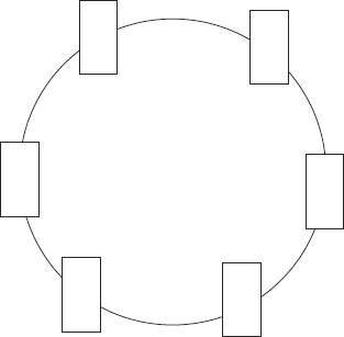
A ring topology connects each system as points on a circle (see Figure 3.6). The connection medium acts as a unidirectional transmission loop. Only one system can transmit data at a time. Traffic management is performed by a token. A token is a digital hall pass that travels around the ring until a system grabs it. A system in possession of the token can transmit data. Data and the token are transmitted to a specific destination. As the data travels around the loop, each system checks to see whether it is the intended recipient of the data. If not, it passes the token on. If so, it reads the data. Once the data is received, the token is released and returns to traveling around the loop until another system grabs it. If any one segment of the loop is broken, all communication around the loop ceases. Some implementations of ring topologies employ a fault tolerance mechanism, such as dual loops running in opposite directions, to prevent single points of failure.
FIGURE 3.6 A ring topology
Bus Topology
A bus topology connects each system to a trunk or backbone cable. All systems on the bus can transmit data simultaneously, which can result in collisions. A collision occurs when two systems transmit data at the same time; the signals interfere with each other. To avoid this, the systems employ a collision avoidance mechanism that basically “listens” for any other currently occurring traffic. If traffic is heard, the system waits a few moments and listens again. If no traffic is heard, the system transmits its data. When data is transmitted on a bus topology, all systems on the network hear the data. If the data is not addressed to a specific system, that system just ignores the data. The benefit of a bus topology is that if a single segment fails, communications on all other segments continue uninterrupted. However, the central trunk line remains a single point of failure.
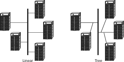
There are two types of bus topologies: linear and tree. A linear bus topology employs a single trunk line with all systems directly connected to it. A tree topology employs a single trunk line with branches that can support multiple systems. Figure 3.7 illustrates both types. The primary reason a bus is rarely if ever used today is that it must be terminated at both ends and any disconnection can take down the entire network.
FIGURE 3.7 A linear topology and a tree bus topology
Star Topology
A star topology employs a centralized connection device. This device can be a simple hub or switch. Each system is connected to the central hub by a dedicated segment (see Figure 3.8). If any one segment fails, the other segments can continue to function. However, the central hub is a single point of failure. Generally, the star topology uses less cabling than other topologies and makes the identification of damaged cables easier.
FIGURE 3.8 A star topology
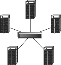
A logical bus and a logical ring can be implemented as a physical star. Ethernet is a bus-based technology. It can be deployed as a physical star, but the hub or switch device is actually a logical bus connection device. Likewise, Token Ring is a ring-based technology. It can be deployed as a physical star using a multistation access unit (MAU). An MAU allows for the cable segments to be deployed as a star while internally the device makes logical ring connections.
Mesh Topology
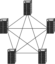
A mesh topology connects systems to other systems using numerous paths (see Figure 3.9). A full mesh topology connects each system to all other systems on the network. A partial mesh topology connects many systems to many other systems. Mesh topologies provide redundant connections to systems, allowing multiple segment failures without seriously affecting connectivity.
FIGURE 3.9 A mesh topology
TCP/IP Overview
The most widely used protocol suite is TCP/IP, but it is not just a single protocol; rather, it is a protocol stack comprising dozens of individual protocols (see Figure 3.10). TCP/IP is a platform-independent protocol based on open standards. However, this is both a benefit and a drawback. TCP/IP can be found in just about every available operating system, but it consumes a significant amount of resources and is relatively easy to hack into because it was designed for ease of use rather than for security.
FIGURE 3.10 The four layers of TCP/IP and its component protocols
TCP/IP can be secured using VPN links between systems. VPN links are encrypted to add privacy, confidentiality, and authentication and to maintain data integrity. Protocols used to establish VPNs are Point-to-Point Tunneling Protocol (PPTP), Layer 2 Tunneling Protocol (L2TP), and Internet Protocol Security (IPSec). Another method to provide protocol-level security is to employ TCP wrappers. A TCP wrapper is an application that can serve as a basic firewall by restricting access to ports and resources based on user IDs or system IDs. Using TCP wrappers is a form of port-based access control.
Transport Layer Protocols
The two primary Transport layer protocols of TCP/IP are TCP and UDP. TCP is a connection-oriented protocol, whereas UDP is a connectionless protocol. When a communication connection is established between two systems, it is done using ports. TCP and UDP each have 65,536 ports. Since port numbers are 16-digit binary numbers, the total number of ports is 216, or 65,536, numbered from 0 through 65,535. A port (also called a socket) is little more than an address number that both ends of the communication link agree to use when transferring data. Ports allow a single IP address to be able to support multiple simultaneous communications, each using a different port number.
The first 1,024 of these ports (0–1,023) are called the well-known ports or the service ports. This is because they have standardized assignments as to the services they support. For example, port 80 is the standard port for web (HTTP) traffic, port 23 is the standard port for Telnet, and port 25 is the standard port for SMTP. You can find a list of ports worth knowing for the exam in the section “Common Application Layer Protocols” later in this chapter. Ports 1024 to 49151 are known as the registered software ports. These are ports that have one or more networking software products specifically registered with the International Assigned Numbers Authority (IANA, www.iana.org) in order to provide a standardized port numbering system for clients attempting to connect to their products. Ports 49152 to 65535 are known as the random, dynamic, or ephemeral ports because they are often used randomly and temporarily by clients as a source port. These random ports are also used by several networking services when negotiating a data transfer pipeline between client and server outside the initial service or registered ports, such as performed by common FTP.
Port Numbers
The IANA recommends that ports 49152 to 65535 be used as dynamic and/or private ports. However, not all OSes abide by this. For example:
- Berkeley Software Distribution (BSD) uses ports 1024 through 4999.
- Many Linux kernels use 32768 to 61000.
- Microsoft, up to and including Windows Server 2003, uses the range 1025 to 5000.
- Windows Vista, Windows 7, and Server 2008 use the IANA range.
- FreeBSD uses the IANA suggested port range since version 4.6.
Transmission Control Protocol (TCP) operates at layer 4 (the Transport layer) of the OSI model. It supports full-duplex communications, is connection oriented, and employs reliable sessions. TCP is connection oriented because it employs a handshake process between two systems to establish a communication session. Upon completion of this handshake process, a communication session that can support data transmission between the client and server is established. The three-way handshake process is as follows:
1. The client sends a SYN (synchronize) flagged packet to the server.
2. The server responds with a SYN/ACK (synchronize and acknowledge) flagged packet back to the client.
3. The client responds with an ACK (acknowledge) flagged packet back to the server.
When a communication session is complete, there are two methods to disconnect the TCP session. First, and most common, is the use of FIN flagged packets instead of SYN flagged packets. Each side of a conversation will transmit a FIN flagged packet once all of its data is transmitted, triggering the opposing side to confirm with an ACK flagged packet. Thus, it takes four packets to gracefully tear down a TCP session. Second is the use of an RST flagged packet, which causes an immediate and abrupt session termination. (Please see the discussion of the TCP header flag later in this section.)
The segments of a TCP transmission are sequenced. This allows the receiver to rebuild the original communication by reordering received segments back into their proper arrangement in spite of the order in which they were received. Data communicated through a TCP session is periodically verified with an acknowledgment signal. The acknowledgment is a hash value of all previously transmitted data. If the server’s own hash of received data does not match the hash value sent by the client, the server asks the client to resend the last collection of data. The number of packets transmitted before an acknowledge packet is sent is known as the transmission window. Data flow is controlled through a mechanism called sliding windows. TCP is able to use different sizes of windows (in other words, a different number of transmitted packets) before sending an acknowledgment. Larger windows allow for faster data transmission, but they should be used only on reliable connections where lost or corrupted data is minimal. Smaller windows should be used when the communication connection is unreliable. TCP should be employed when the delivery of data is required. Sliding windows allow this size to vary dynamically because the reliability of the TCP session changes while in use.
The TCP header is relatively complex when compared to its sister protocol UDP. A TCP header is 20 to 60 bytes long. This header is divided into several sections, or fields, as detailed in TABLE 3.5.
Table 3.5 TCP header construction (ordered from beginning of header to end)
| Size in Bits | Field |
| 16 | Source port |
| 16 | Destination port |
| 32 | Sequence number |
| 4 | Data offset |
| 4 | Reserved for future use |
| 8 | Flags (see TABLE 3.6) |
| 16 | Window size |
| 16 | Checksum |
| 16 | Urgent pointer |
| Variable | Various options; must be a multiple of 32 bits |
All of these fields have unique parameters and requirements, most of which are beyond the scope of the CISSP exam. However, you should be familiar with the details of the flags field. The flags field can contain a designation of one or more flags, or control bits. These flags indicate the function of the TCP packet and request that the recipient respond in a specific manner. The flag field is 8 bits long. Each of the bit positions represents a single flag, or control setting. Each position can be set on with a value of 1 or off with a value of 0. There are some conditions in which multiple flags can be enabled at once (in other words, the second packet in the TCP three-way handshake when both the SYN and ACK flags are set). Table 3.6 details the flag control bits.
Table 3.6 The TCP header flag field values
| Flag Bit Designator | Name | Description |
| CWR | Congestion Window Reduced | Used to manage transmission over congested links; see RFC 3168 |
| ECE | ECN-Echo (Explicit Congestion Notification) | Used to manage transmission over congested links; see RFC 3168 |
| URG | Urgent | Indicates urgent data |
| ACK | Acknowledgment | Acknowledges synchronization or shutdown request |
| PSH | Push | Indicates need to push data immediately to application |
| RST | Reset | Causes immediate disconnect of TCP session |
| SYN | Synchronization | Requests synchronization with new sequencing numbers |
| FIN | Finish | Requests graceful shutdown of TCP session |
An additional important tidbit is that the IP header protocol field value for TCP is 6 (0x06). The protocol field value is the label or flag found in the header of every IP packet that tells the receiving system what type of packet it is. The IP header’s protocol field indicates the identity of the next encapsulated protocol (in other words, the protocol contained in the payload from the current protocol layer, such as ICMP or IGMP, or the next layer up, such as TCP or UDP). Think of it as like the label on a mystery-meat package wrapped in butcher paper you pull out of the freezer. Without the label, you would have to open it and inspect it to figure out what it was. But with the label, you can search or filter quickly to find items of interest. For a list of other protocol field values, please visit www.iana.org/assignments/protocol-numbers.
![]()
Protocol Discovery
Hundreds of protocols are in use on a typical TCP/IP network at any given moment. Using a sniffer, you can discover what protocols are in use on your current network. Before using a sniffer, though, make sure you have the proper permission or authorization. Without approval, using a sniffer can be considered a security violation because it enables you to eavesdrop on unprotected network communications. If you can’t obtain permission at work, try this on your home network instead. Download and install a sniffer, such as Wireshark. Then use the sniffer to monitor the activity on your network. Discover just how many protocols (in other words, subprotocols of TCP/IP) are in use on your network.
Another step in using a sniffer is to analyze the contents of captured packets. Pick out a few different protocol packets, and inspect their headers. Look for TCP, ICMP, ARP, and UDP packets. Compare the contents of their headers. Try to locate any special flags or field codes used by the protocols. You’ll likely discover that there is a lot more going on within a protocol than you ever imagined.
User Datagram Protocol (UDP) also operates at layer 4 (the Transport layer) of the OSI model. It is a connectionless “best-effort” communications protocol. It offers no error detection or correction, does not use sequencing, does not use flow control mechanisms, does not use a pre-established session, and is considered unreliable. UDP has very low overhead and thus can transmit data quickly. However, UDP should be used only when the delivery of data is not essential. UDP is often employed by real-time or streaming communications for audio and/or video. The IP header protocol field value for UDP is 17 (0x11).
As mentioned earlier, the UDP header is relatively simple in comparison with the TCP header. A UDP header is 8 bytes long. This header is divided into several sections or fields, as detailed in TABLE 3.7.
Table 3.7 UDP header construction
| Size in Bits | Field |
| 16 | Source port |
| 16 | Destination port |
| 16 | Message length |
| 16 | Checksum |
Network Layer Protocols
Another important protocol in the TCP/IP protocol suite operates at the Network layer of the OSI model, namely, Internet Protocol (IP). IP provides route addressing for data packets. It is this route addressing that is the foundation of global Internet communications since it provides a means of identity and prescribes transmission paths. Similar to UDP, IP is connectionless and is an unreliable datagram service. IP does not offer guarantees that packets will be delivered or that packets will be delivered in the correct order, and it does not guarantee that packets will not be delivered more than once. Thus, you must employ TCP on IP to gain reliable and controlled communication sessions.
IPv4 vs. IPv6
IPv4 is the version of Internet Protocol that is most widely used around the world. However, a new version known as IPv6 is primed to take over and improve network addressing and routing. IPv4 uses a 32-bit addressing scheme, while IPv6 uses 128 bits for addressing. IPv6 offers many new features that are not available in IPv4. Some of IPv6’s new features are scoped addresses, autoconfiguration, and QoS priority values. Scoped addresses give administrators the ability to group and then block or allow access to network services, such as file servers or printing. Autoconfiguration removes the need for both DHCP and NAT. QoS priority values allow for traffic management based on prioritized content.
IPv6 is supported by most operating systems released since 2000 either natively or via an add-in. However, IPv6 has been slowly adopted. Most of the IPv6 networks are currently located in private networks such as large corporations, research laboratories, and universities.
Other protocols at the OSI model Network layer include ICMP and IGMP.
ICMP
Internet Control Message Protocol (ICMP) is used to determine the health of a network or a specific link. ICMP is utilized by ping, traceroute, pathping, and other network management tools. The ping utility employs ICMP echo packets and bounces them off remote systems. Thus, you can use ping to determine whether the remote system is online, whether the remote system is responding promptly, whether the intermediary systems are supporting communications, and the level of performance efficiency at which the intermediary systems are communicating. The ping utility includes a redirect function that allows the echo responses to be sent to a different destination than the system of origin. Unfortunately, the features of ICMP are often exploited in various forms of bandwidth-based denial-of-service attacks, such as Ping of Death, Smurf, and Ping Floods.
You should be aware of several important details regarding ICMP. First, the IP header protocol field value for ICMP is 1 (0x01). Second, the type field in the ICMP header defines the type or purpose of the message contained within the ICMP payload. There are more than 40 defined types, but only 7 are commonly used (see TABLE 3.8). You can find a complete list of the ICMP type field values at www.iana.org/assignments/icmp-parameters. It may be worth noting that many of the types listed may also support codes. A code is simply an additional data parameter offering more detail about the function or purpose of the ICMP message payload.
Table 3.8 Common ICMP type field values
| Type | Function |
| 0 | Echo reply |
| 3 | Destination unreachable |
| 5 | Redirect |
| 8 | Echo request |
| 9 | Router advertisement |
| 10 | Router solicitation |
| 11 | Time exceeded |
IGMP
Internet Group Management Protocol (IGMP) allows systems to support multicasting. Multicasting is the transmission of data to multiple specific recipients. (RFC 1112 discusses the requirements to perform IGMP multicasting.) IGMP is used by IP hosts to register their dynamic multicast group membership. It is also used by connected routers to discover these groups. Through the use of IGMP multicasting, a server can initially transmit a single data signal rather than a separate initial data signal for each intended recipient. With IGMP, the single initial signal is multiplied at the router if divergent pathways exist to the intended recipients. The IP header protocol field value for IGMP is 2 (0x02).
ARP and Reverse ARP
Address Resolution Protocol (ARP) and Reverse Address Resolution Protocol (RARP) are essential to the interoperability of logical and physical addressing schemes. ARP is used to resolve IP addresses (32-bit binary number for logical addressing) into Media Access Control (MAC) addresses (48-bit binary number for physical addressing). Traffic on a network segment (for example, cables across a hub) is directed from its source system to its destination system using MAC addresses. RARP is used to resolve MAC addresses into IP addresses.
Both ARP and RARP function using caching and broadcasting. The first step in resolving an IP address into a MAC address, or vice versa, is to check the local ARP cache. If the needed information is already present in the ARP cache, it is used. This activity is sometimes abused using a technique called ARP cache poisoning where an attacker inserts bogus information into the ARP cache. If the ARP cache does not contain the necessary information, an ARP request in the form of a broadcast is transmitted. If the owner of the queried address is in the local subnet, it can respond with the necessary information. If not, the system will use its default gateway to transmit its communications. Then, the default gateway (in other words, a router) will need to perform its own ARP or RARP process.
IP Classes
Basic knowledge of IP addressing and IP classes is a must for any security professional. If you are rusty on addressing, subnetting, classes, and other related topics, take the time to refresh yourself. TABLE 3.9 and TABLE 3.10 provide a quick overview of the key details of classes and default subnets. A full Class A subnet supports 16,777,214 hosts; a full class B subnet supports 65,534 hosts; and a full Class C subnet supports 254 hosts. Class D is used for multicasting, while Class E is reserved for future use.
Table 3.9 IP classes
| Class | First Binary Digits | Decimal Range of First Octet |
| A | 0 | 1–126 |
| B | 10 | 128–191 |
| C | 110 | 192–223 |
| D | 1110 | 224–239 |
| E | 1111 | 240–255 |
Table 3.10 IP classes’ default subnet masks
| Class | Default Subnet Mask | CIDR Equivalent |
| A | 255.0.0.0 | /8 |
| B | 255.255.0.0 | /16 |
| C | 255.255.255.0 | /24 |
Note that the entire Class A network of 127 was set aside for the loopback address, although only a single address is actually needed for that purpose.
Another option for subnetting is to use Classless Inter-Domain Routing (CIDR) notation. CIDR uses mask bits rather than a full dotted-decimal notation subnet mask. Thus, instead of 255.255.0.0, a CIDR is added to the IP address after a slash, as in 172.16.1.1/16, for example. One significant benefit of CIDR over traditional subnet-masking techniques is the ability to combine multiple noncontiguous sets of addresses into a single subnet. For example, it is possible to combine several Class C subnets into a single larger subnet grouping. If CIDR piques your interest, see the CIDR article on Wikipedia or visit the IETF’s RFC for CIDR at http://tools.ietf.org/html//rfc4632 for more information.
Common Application Layer Protocols
In the Application layer of the TCP/IP model (which includes the Session, Presentation, and Application layers of the OSI model) reside numerous application- or service-specific protocols. A basic knowledge of these protocols and their relevant service ports is important for the CISSP exam:
Telnet, TCP port 23 This is a terminal emulation network application that supports remote connectivity for executing commands and running applications but that does not support transfer of files.
File Transfer Protocol (FTP), TCP ports 20 and 21 This is a network application that supports an exchange of files that requires anonymous or specific authentication.
Trivial File Transfer Protocol (TFTP), UDP port 69 This is a network application that supports an exchange of files that does not require authentication.
Simple Mail Transfer Protocol (SMTP), TCP port 25 This is a protocol used to transmit email messages from a client to an email server and from one email server to another.
Post Office Protocol (POP3), TCP port 110 This is a protocol used to pull email messages from an inbox on an email server down to an email client.
Internet Message Access Protocol (IMAP 4), TCP port 143 This is a protocol used to pull email messages from an inbox on an email server down to an email client. IMAP is more secure than POP3 and offers the ability to pull headers down from the email server as well as to delete messages directly off the email server without having to download to the local client first.
Dynamic Host Configuration Protocol (DHCP), UDP ports 67 and 68 DHCP uses port 67 for server point-to-point response and port 68 for client request broadcast. It is used to assign TCP/IP configuration settings to systems upon bootup. DHCP enables centralized control of network addressing.
Hypertext Transport Protocol (HTTP), TCP port 80 This is the protocol used to transmit web page elements from a web server to web browsers.
Secure Sockets Layer (SSL), TCP port 443 (for HTTP encryption) This is a VPN-like security protocol that operates at the Transport layer. SSL was originally designed to support secured web communications (HTTPS) but is capable of securing any Application-layer protocol communications.
Line Print Daemon (LPD), TCP port 515 This is a network service that is used to spool print jobs and to send print jobs to printers.
X Window, TCP ports 6000–6063 This is a GUI API for command-line operating systems.
Bootstrap Protocol (BootP), UDP ports 67 and 68 This is a protocol used to connect diskless workstations to a network through autoassignment of IP configuration and download of basic OS elements. BootP is the forerunner to Dynamic Host Configuration Protocol (DHCP).
Network File System (NFS), TCP port 2049 This is a network service used to support file sharing between dissimilar systems.
Simple Network Management Protocol (SNMP), UDP port 161 (UDP port 162 for trap messages) This is a network service used to collect network health and status information by polling monitoring devices from a central monitoring station.
TCP/IP Vulnerabilities
TCP/IP’s vulnerabilities are numerous. Improperly implemented TCP/IP stacks in various operating systems are vulnerable to buffer overflows, SYN flood attacks, various DoS attacks, fragment attacks, oversized packet attacks, spoofing attacks, man-in-the-middle attacks, hijack attacks, and coding error attacks.
In addition to these intrusive attacks, TCP/IP (as well as most protocols) is also subject to passive attacks via monitoring or sniffing. Network monitoring is the act of monitoring traffic patterns to obtain information about a network. Packet sniffing is the act of capturing packets from the network in hopes of extracting useful information from the packet contents. Effective packet sniffers can extract usernames, passwords, email addresses, encryption keys, credit card numbers, IP addresses, system names, and so on.
Domain Name Resolution
Addressing and naming are important components that make network communications possible. Without addressing schemes, networked computers would not be able to distinguish one computer from another or specify the destination of a communication. Likewise, without naming schemes, humans would have to remember and rely upon numbering systems to identify computers. It is much easier to remember Google.com than 64.233.187.99. Thus, most naming schemes were enacted for human use rather than computer use.
It is reasonably important to grasp the basic ideas of addressing and numbering as used on TCP/IP-based networks. There are three different layers to be aware of. First, the top layer is the domain name. The second or middle layer is the IP address. The third, or bottom, layer is the MAC address. The MAC address, or hardware address, is a “permanent” physical address. The IP address is a “temporary” logical address assigned over or onto the MAC address. The domain name or computer name is a “temporary” human-friendly convention assigned over or onto the IP address.
“Permanent” and “Temporary”
The reason these two adjectives are within quotation marks is that they are not completely accurate. MAC addresses are designed to be permanent physical addresses. However, some NICs support MAC address changes, and most modern operating systems do as well (including Windows and Linux). When the NIC supports the change, the change occurs on the hardware. When the OS supports the change, the change is only in memory, but it looks like a hardware change to all other network entities.
An IP address is temporary because it is a logical address and could be changed at any time, either by DHCP or by an administrator. However, there are instances where systems are statically assigned an IP address. Likewise, computer names or DNS names are logical and thus able to be modified by an administrator.
This system of naming and addressing grants each networking component the information it needs while making its use of that information as simple as possible. Humans get human-friendly domain names, networking protocols get router-friendly IP addresses, and the network interfaces get physical addresses. However, all three of these schemes must be linked together to allow interoperability between them. Thus, the Domain Name System (DNS) and the ARP/RARP system were developed. DNS resolves a human-friendly domain name into its IP address equivalent. Then, ARP resolves the IP address into its MAC address equivalent. Both of these resolutions also have an inverse, namely, DNS reverse lookups and RARP (please see the section “ARP and Reverse ARP” earlier in this chapter).
Further Reading on DNS
For an excellent primer to advanced discussion on DNS, its operation, known issues, and the Dan Kaminski vulnerability, please visit “An Illustrated Guide to the Kaminsky DNS Vulnerability” at http://unixwiz.net/techtips/iguide-kaminsky-dns-vuln.html.
For a look into the future of DNS, specifically the defense against the Kaminski vulnerability, visit www.dnssec.net.
Internet/Intranet/Extranet Components
The Internet is host to countless information services and numerous applications, including the Web, email, FTP, Telnet, newsgroups, chat, and so on. The Internet is also home to malicious people whose primary goal is to locate your computer and extract valuable data from it, use it to launch further attacks, or damage it in some way. You should be familiar with the Internet and able to readily identify its benefits and drawbacks from your own online experiences. Because of the success and global use of the Internet, many of its technologies were adapted or integrated into the private business network. This created two new forms of networks: intranets and extranets.
An intranet is a private network that is designed to host the same information services found on the Internet. Networks that rely upon external servers (in other words, ones positioned on the public Internet) to provide information services internally are not considered intranets. Intranets provide users with access to the Web, email, and other services on internal servers that are not accessible to anyone outside the private network.
An extranet is a cross between the Internet and an intranet. An extranet is a section of an organization’s network that has been sectioned off so that it acts as an intranet for the private network but also serves information to the public Internet. An extranet is often reserved for use by specific partners or customers. It is rarely on a public network. An extranet for public consumption is typically labeled a demilitarized zone (DMZ) or perimeter network.
When you’re designing a secure network (whether a private network, an intranet, or an extranet), you must evaluate numerous networking devices. Not all of these components are necessary for a secure network, but they are all common network devices that may have an impact on network security.
Firewalls
Firewalls are essential tools in managing and controlling network traffic. A firewall is a network device used to filter traffic and is typically deployed between a private network and a link to the Internet, but it can be deployed between departments within an organization. Without firewalls, it would not be possible to prevent malicious traffic from the Internet from entering into your private network. Firewalls filter traffic based on a defined set of rules, also called filters or access control lists. They are basically a set of instructions that are used to distinguish authorized traffic from unauthorized and/or malicious traffic. Only authorized traffic is allowed to cross the security barrier provided by the firewall.
Firewalls are useful for blocking or filtering traffic. They are most effective against unrequested traffic and attempts to connect from outside the private network as well as for blocking known malicious data, messages, or packets based on content, application, protocol, port, or source address. They are capable of hiding the structure and addressing scheme of a private network from the public. Most firewalls offer extensive logging, auditing, and monitoring capabilities as well as alarms and basic intrusion detection system (IDS) functions. Firewalls are typically unable to block viruses or malicious code (i.e., firewalls do not typically scan traffic as an antivirus scanner would) transmitted through otherwise authorized communication channels, prevent unauthorized but accidental or intended disclosure of information by users, prevent attacks by malicious users already behind the firewall, or protect data after it passes out of or into the private network. However, you can add these features through special add-in modules or companion products, such as antivirus scanners and IDS tools. There are firewall appliances that are preconfigured to perform all (or most) of these “add-on” functions natively.
In addition to logging network traffic activity, firewalls should log several other events as well:
- A reboot of the firewall
- Proxies or dependencies being unable to or not starting
- Proxies or other important services crashing or restarting
- Changes to the firewall configuration file
- A configuration or system error while the firewall is running
Firewalls are only one part of an overall security solution. With a firewall, many of the security mechanisms are concentrated in one place, and thus they may be a single point of failure. Firewall failure is most commonly caused by human error and misconfiguration. Firewalls provide protection only against traffic that crosses the firewall from one subnet to another. They offer no protection against traffic within a subnet (in other words, behind a firewall).
There are four basic types of firewalls: static packet-filtering firewalls, application-level gateway firewalls, circuit-level gateway firewalls, and stateful inspection firewalls. There are also ways to create hybrid or complex gateway firewalls by combining two or more of these firewall types into a single firewall solution. In most cases, having a multilevel firewall provides greater control over filtering traffic. Regardless, we’ll cover the various firewall types and discuss firewall deployment architectures as well.
Static Packet-Filtering Firewalls
A static packet-filtering firewall filters traffic by examining data from a message header. Usually, the rules are concerned with source, destination, and port addresses. Using static filtering, a firewall is unable to provide user authentication or to tell whether a packet originated from inside or outside the private network, and it is easily fooled with spoofed packets. Static packet-filtering firewalls are known as first-generation firewalls; they operate at layer 3 (the Network layer) of the OSI model. They can also be called screening routers or common routers.
Application-Level Gateway Firewalls
An application-level gateway firewall is also called a proxy firewall. A proxy is a mechanism that copies packets from one network into another; the copy process also changes the source and destination addresses to protect the identity of the internal or private network. An application-level gateway firewall filters traffic based on the Internet service (in other words, the application) used to transmit or receive the data. Each type of application must have its own unique proxy server. Thus, an application-level gateway firewall comprises numerous individual proxy servers. This type of firewall negatively affects network performance because each packet must be examined and processed as it passes through the firewall. Application-level gateways are known as second-generation firewalls, and they operate at the Application layer (layer 7) of the OSI model.
Circuit-Level Gateway Firewalls
Circuit-level gateway firewalls are used to establish communication sessions between trusted partners. They operate at the Session layer (layer 5) of the OSI model. SOCKS (from sockets, as in TCP/IP ports) is a common implementation of a circuit-level gateway firewall. Circuit-level gateway firewalls, also known as circuit proxies, manage communications based on the circuit, not the content of traffic. They permit or deny forwarding decisions based solely on the endpoint designations of the communication circuit (in other words, the source and destination addresses and service port numbers). Circuit-level gateway firewalls are considered second-generation firewalls because they represent a modification of the application-level gateway firewall concept.
Stateful Inspection Firewalls
Stateful inspection firewalls (also known as dynamic packet filtering firewalls) evaluate the state or the context of network traffic. By examining source and destination addresses, application usage, source of origin, and relationship between current packets and the previous packets of the same session, stateful inspection firewalls are able to grant a broader range of access for authorized users and activities and actively watch for and block unauthorized users and activities. Stateful inspection firewalls generally operate more efficiently than application-level gateway firewalls. They are known as third-generation firewalls, and they operate at the Network and Transport layers (layers 3 and 4) of the OSI model.
Multihomed Firewalls
Some firewall systems have more than one interface. For instance, a multihomed firewall must have at least two interfaces to filter traffic (they’re also known as dual-homed firewalls). All multihomed firewalls should have IP forwarding disabled to force the filtering rules to control all traffic rather than allowing a software-supported shortcut between one interface and another. A bastion host or a screened host is just a firewall system logically positioned between a private network and an untrusted network. Usually, the bastion host is located behind the router that connects the private network to the untrusted network. All inbound traffic is routed to the bastion host, which in turn acts as a proxy for all the trusted systems within the private network. It is responsible for filtering traffic coming into the private network as well as for protecting the identity of the internal client.
![]()
The word bastion comes from medieval castle architecture. A bastion guardhouse was positioned in front of the main entrance to serve as a first layer of protection. Using this term to describe a firewall indicates that the firewall is acting as a sacrificial host that will receive all inbound attacks.
A screened subnet is similar to the screened host (in other words, the bastion host) in concept, except a subnet is placed between two routers and the bastion host(s) is located within that subnet. All inbound traffic is directed to the bastion host, and only traffic proxied by the bastion host can pass through the second router into the private network. This creates a subnet where some external visitors are allowed to communicate with resources offered by the network. This is the concept of a DMZ, which is a network area (usually a subnet) that is designed to be accessed by outside visitors but that is still isolated from the private network of the organization. The DMZ is often the host of public web, email, file, and other resource servers.
Firewall Deployment Architectures
There are three commonly recognized firewall deployment architectures: single tier, two tier, and three tier (also known as multitier). As you can see in Figure 3.11, a single-tier deployment places the private network behind a firewall, which is then connected through a router to the Internet (or some other untrusted network). Single-tier deployments are useful against generic attacks only. This architecture offers only minimal protection.
FIGURE 3.11 Three firewall deployment architectures
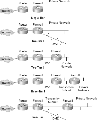
A two-tier deployment architecture may be one of two different designs. One uses a firewall with three or more interfaces. The other uses two firewalls in a series. This allows for a DMZ or a publicly accessible extranet. In the first design, the DMZ is located off one of the interfaces of the primary firewall, while in the second design the DMZ is located between the two serial firewalls. The DMZ is used to host information server systems to which external users should have access. The firewall routes traffic to the DMZ or the trusted network according to its strict filtering rules. This architecture introduces a moderate level of routing and filtering complexity.
A three-tier deployment architecture is the deployment of multiple subnets between the private network and the Internet separated by firewalls. Each subsequent firewall has more stringent filtering rules to restrict traffic to only trusted sources. The outermost subnet is usually a DMZ. A middle subnet can serve as a transaction subnet where systems needed to support complex web applications in the DMZ reside. The third, or backend, subnet can support the private network. This architecture is the most secure; however, it is also the most complex to design, implement, and manage.
Other Network Devices
You’ll use numerous devices when constructing a network. Strong familiarity with the components of networks can assist you in designing an IT infrastructure that avoids single points of failure and provides strong support for availability.
Collisions vs. Broadcasts
A collision occurs when two systems transmit data at the same time onto a connection medium that supports only a single transmission path. A broadcast occurs when a single system transmits data to all possible recipients. Generally, collisions are always something to avoid and prevent, while broadcasts have useful purposes from time to time. The management of collisions and broadcasts introduces a new term known as domains.
A collision domain is a group of networked systems that could cause a collision if any two (or more) of the systems in that group transmitted simultaneously. Any system outside the collision domain cannot cause a collision with any member of that collision domain.
A broadcast domain is a group of networked systems in which all other members receive a broadcast signal when one of the members of the group transmits it. Any system outside a broadcast domain would not receive a broadcast from that broadcast domain.
As you design and deploy a network, you should consider how collision domains and broadcast domains will be managed. Collision domains are divided by using any layer 2 or higher device, and broadcast domains are divided by using any layer 3 or higher device. When a domain is divided, it means that systems on opposite sides of the deployed device are members of different domains.
These are some of the devices in a network:
Repeaters, concentrators, and amplifiers Repeaters, concentrators, and amplifiers are used to strengthen the communication signal over a cable segment as well as connect network segments that use the same protocol. These devices can be used to extend the maximum length of a specific cable type by deploying one or more repeaters along a lengthy cable run. Repeaters, concentrators, and amplifiers operate at OSI layer 1. Systems on either side of a repeater, concentrator, or amplifier are part of the same collision domain and broadcast domain.
Hubs Hubs are used to connect multiple systems in a star topology and connect network segments that use the same protocol. They repeat inbound traffic over all outbound ports. This ensures that the traffic will reach its intended host. A hub is a multiport repeater. Hubs operate at OSI layer 1. Systems on either side of a hub are part of the same collision and broadcast domains. Most organizations have a no-hub security policy to limit or reduce the risk of sniffing attacks.
Bridges A bridge is used to connect two networks together, even networks of different topologies, cabling types, and speeds, in order to connect network segments that use the same protocol. A bridge forwards traffic from one network to another. Bridges that connect networks using different transmission speeds may have a buffer to store packets until they can be forwarded to the slower network. This is known as a store-and-forward device. Bridges operate at OSI layer 2. Systems on either side of a bridge are part of the same broadcast domain but are in different collision domains.
Switches Rather than using a hub, you might consider using a switch, or intelligent hub. Switches know the addresses of the systems connected on each outbound port. Instead of repeating traffic on every outbound port, a switch repeats traffic only out of the port on which the destination is known to exist. Switches offer greater efficiency for traffic delivery, create separate collision domains, and improve the overall throughput of data. Switches can also create separate broadcast domains when used to create VLANs. In such configurations, broadcasts are allowed within a single VLAN but not allowed to cross unhindered from one VLAN to another. Switches operate primarily at OSI layer 2. When switches have additional features, such as routing, they can operate at OSI layer 3 as well (such as when routing between VLANs). Systems on either side of a switch operating at layer 2 are part of the same broadcast domain but are in different collision domains. Systems on either side of a switch operating at layer 3 are part of different broadcast domains and different collision domains. Switches are used to connect network segments that use the same protocol.
Routers Routers are used to control traffic flow on networks and are often used to connect similar networks and control traffic flow between the two. They can function using statically defined routing tables, or they can employ a dynamic routing system. There are numerous dynamic routing protocols, such as RIP, OSPF, and BGP. Routers operate at OSI layer 3. Systems on either side of a router are part of different broadcast domains and different collision domains. Routers are used to connect network segments that use the same protocol.
Brouter Brouters are combination devices comprising a router and a bridge. A brouter attempts to route first, but if that fails, it defaults to bridging. Thus, a brouter operates primarily at layer 3 but can operate at layer 2 when necessary. Systems on either side of a brouter operating at layer 3 are part of different broadcast domains and different collision domains. Systems on either side of a brouter operating at layer 2 are part of the same broadcast domain but are in different collision domains. Brouters are used to connect network segments that use the same protocol.
Gateways A gateway connects networks that are using different network protocols. A gateway is responsible for transferring traffic from one network to another by transforming the format of that traffic into a form compatible with the protocol or transport method used by each network. Gateways, also known as protocol translators, can be stand-alone hardware devices or a software service (for example, an IP-to-IPX gateway). Systems on either side of a gateway are part of different broadcast domains and different collision domains. Gateways are used to connect network segments that use different protocols. There are many types of gateways, including data, mail, application, secure, and Internet. Gateways typically operate at OSI layer 7.
Proxies A proxy is a form of gateway that does not translate across protocols. Instead, proxies serve as mediators, filters, caching servers, and even NAT/PAT servers for a network. A proxy performs a function or requests a service on behalf of another system and connects network segments that use the same protocol. Proxies are most often used in the context of providing clients on a private network with Internet access while protecting the identity of the clients. A proxy accepts requests from clients, alters the source address of the requester, maintains a mapping of requests to clients, and sends the altered request packets out. This mechanism is commonly known as Network Address Translation (NAT). Once a reply is received, the proxy server determines which client it is destined for by reviewing its mappings and then sends the packets on to the client. Systems on either side of a proxy are part of different broadcast domains and different collision domains.
Network Infrastructure Inventory
If you can gain approval from your organization, perform a general survey or inventory of the significant components comprising your network. See how many different network devices you can locate within your network. Also, do you notice any patterns of device deployment, such as devices always deployed in parallel or in series? Is the exterior of a device usually sufficient to indicate its function, or must you look up its model number?
LAN extender A LAN extender is a remote access, multilayer switch used to connect distant networks over WAN links. This is a strange beast of a device in that it creates WANs, but marketers of this device steer clear of the term WAN and use only LAN and extended LAN. The idea behind this device was to make the terminology easier to understand and easier to sell than a normal WAN device with complex concepts and terms tied to it. Ultimately, it was the same product as a WAN switch or WAN router. (We agree with Douglas Adams, who believed the marketing people should be shipped out with the lawyers and phone sanitizers on the first spaceship to the far end of the universe.)
![]()
While managing network security with filtering devices such as firewalls and proxies is important, we must not overlook the need for endpoint security. Endpoints are the ends of a network communication link. One end is often at a server where a resource resides, and the other end is often a client making a request to use a network resource. Even with secured communication protocols, it is still possible for abuse, misuse, oversight, or malicious action to occur across the network because it originated at an endpoint. All aspects of security from one end to the other, often called end-to-end security, must be addressed. Any unsecured point will be discovered eventually and abused.
Remote Access Security Management
Telecommuting, or remote connectivity, has become a common feature of business computing. Remote access is the ability of a distant client to establish a communication session with a network. This can take the form of using a modem to dial up directly to a remote access server, connecting to a network over the Internet through a VPN, or even connecting to a terminal server system through a thin-client connection. The first two examples use fully capable clients. They establish connections just as if they were directly connected to the LAN. The last example, with a terminal server, establishes a connection from a thin client. In such a situation, all computing activities occur on the terminal server system rather than on the distant client.
When remote access capabilities are deployed in any environment, security must be considered and implemented to provide protection for your private network against remote access complications. Remote access users should be stringently authenticated before being granted access. Only those users who specifically need remote access for their assigned work tasks should be granted permission to establish remote connections. All remote communications should be protected from interception and eavesdropping. This usually requires an encryption solution that provides strong protection for the authentication traffic as well as all data transmission.
It is important to establish secure communication channels before initiating the transmission of sensitive, valuable, or personal information. Remote access security in general is important, but you should also focus on the specifics of the various work tasks that require secured communications. This can include voice over IP (VoIP) and multimedia collaboration.
VoIP is a technology that encapsulates audio into IP packets in order to support telephone calls over TCP/IP network connections. VoIP has become a popular and inexpensive telephony solution for companies and individuals worldwide. It is important to keep security in mind when selecting a VoIP solution to ensure that it provides the privacy and security you expect. Some VoIP systems are essentially plain-form communications that are easily intercepted and eavesdropped; others are highly encrypted, and any attempt to interfere or wiretap is deterred and thwarted.
Multimedia collaboration is the use of various multimedia-supporting communication solutions to enhance distance collaboration. Collaboration occurs when people can work on a project together. Often, collaboration allows workers to work simultaneously as well as across different time frames. Collaboration can also be used for tracking changes and including multimedia functions. Collaboration can incorporate email, chat, VoIP, videoconferencing, use of a whiteboard, online document editing, real-time file exchange, versioning control, and other tools. Collaboration often is a feature of advanced forms of remote meeting technology. No matter what form of multimedia collaboration is implemented, the attendant security implications must be evaluated. Does the service use strong authentication techniques? Does the communication occur across an open protocol or an encrypted tunnel? Does the solution allow for true deletion of content? Are activities of users audited and logged? Multimedia collaboration can improve the work environment and allow for input from a wider range of diverse workers across the globe, but this is only a benefit if the security of the solution can be ensured.
When outlining your remote access security management strategy, be sure to address the following issues:
Remote connectivity technology Each type of connection has its own unique security issues. Fully examine every aspect of your connection options. This can include modems, DSL, ISDN, wireless networking, and cable modems.
Transmission protection There are several forms of encrypted protocols, encrypted connection systems, and encrypted network services or applications. Use the appropriate combination of secured services for your remote connectivity needs. This can include VPNs, SSL, TLS, Secure Shell (SSH), IPSec, and L2TP.
Authentication protection In addition to protecting data traffic, you must ensure that all logon credentials are properly secured. This requires the use of an authentication protocol and may mandate the use of a centralized remote access authentication system. This can include Password Authentication Protocol (PAP), Challenge Handshake Authentication Protocol (CHAP), Extensible Authentication Protocol (EAP), Remote Authentication Dial-In User Service (RADIUS), and Terminal Access Controller Access Control System (TACACS).
Remote user assistance Remote access users may periodically require technical assistance. You must have a means established to provide this as efficiently as possible. This can include addressing software and hardware issues, user training issues, and so on.
The ability to use remote access or establish a remote connection should be tightly controlled. As mentioned earlier, only those users who require remote access for their work tasks should be granted such access. You can control and restrict the use of remote connectivity by using filters, rules, or access controls based on user identity, workstation identity, protocol, application, content, and time of day. To provide protection and restriction of remote access only to authorized users, you can use callback and caller ID. Callback is a mechanism that disconnects a remote user upon initial contact and then immediately attempts to reconnect to them using a predefined phone number (in other words, the number defined in the user account’s security database). Callback does have a user-defined mode. However, this mode is not used for security; it is used to reverse toll charges to the company rather than charging the remote client. Caller ID verification can be used for the same purpose as callback—by verifying the physical location (via phone number) of the authorized user.
It should be a standard element in your security policy that no unauthorized modems be present on any system connected to the private network. You may need to further specify this policy by indicating that those with portable systems must either remove their modems before connecting to the network or boot with a hardware profile that disables the modem’s device driver.
Network and Protocol Security Mechanisms
TCP/IP is the primary protocol suite used on most networks and on the Internet. It is a robust protocol suite, but it has numerous security deficiencies. In an effort to improve the security of TCP/IP, many subprotocols, mechanisms, or applications have been developed to protect the confidentiality, integrity, and availability of transmitted data. It is important to remember that even with the foundational protocol suite of TCP/IP, there are literally hundreds, if not thousands, of individual protocols, mechanisms, and applications in use across the Internet. Some of them are designed to provide security services. Some protect integrity, others protect confidentiality, and others provide authentication and access control. In the next sections, we’ll discuss some of the more common network and protocol security mechanisms.
Secure Communications Protocols
Protocols that provide security services for application-specific communication channels are called secure communication protocols. They are as follows:
Simple Key Management for IP (SKIP) This is an encryption tool used to protect sessionless datagram protocols. SKIP was designed to integrate with IPSec; it functions at layer 3. SKIP is able to encrypt any subprotocol of the TCP/IP suite. SKIP was replaced by IKE in 1998.
SoftWare IP Encryption (SWIPE) This is another layer 3 security protocol for IP. It provides authentication, integrity, and confidentiality using an encapsulation protocol.
Secure Remote Procedure Call (S-RPC) This is an authentication service and is simply a means to prevent unauthorized execution of code on remote systems.
Secure Sockets Layer (SSL) This is an encryption protocol developed by Netscape to protect the communications between a web server and a web browser. SSL can be used to secure web, email, FTP, or even Telnet traffic. It is a session-oriented protocol that provides confidentiality and integrity. SSL is deployed using a 40-bit key or a 128-bit key. SSL is superseded by Transport Layer Security (TLS). TLS functions in the same general manner as SSL, but it uses stronger authentication and encryption protocols.
Secure Electronic Transaction (SET) This is a security protocol for the transmission of transactions over the Internet. SET is based on Rivest, Shamir, and Adelman (RSA) encryption and Data Encryption Standard (DES). It has the support of major credit card companies, such as Visa and MasterCard. However, SET has not been widely accepted by the Internet in general; instead, SSL/TLS encrypted sessions are the preferred mechanism for secure e-commerce.
These five secure communication protocols (SKIP, SWIPE, S-RPC, SSL/TLS, and SET) are just a few examples of options available. Keep in mind that there are many other secure protocols, such as IPSec (discussed in Chapter 4).
Dial-Up Protocols
When a remote connection link is established, a protocol must be used to govern how the link is actually created and to establish a common communication foundation for other protocols to work over. Dial-up protocols such as those described in the following list provide this function, not only for true dial-up links, but also for some VPN links:
Point-to-Point Protocol (PPP) This is a full-duplex protocol used for transmitting TCP/IP packets over various non-LAN connections, such as modems, ISDN, VPNs, Frame Relay, and so on. PPP is widely supported and is the transport protocol of choice for dial-up Internet connections. PPP authentication is protected through the use of various protocols, such as CHAP or PAP. PPP is a replacement for SLIP and can support any LAN protocol, not just TCP/IP.
Serial Line Internet Protocol (SLIP) This is an older technology developed to support TCP/IP communications over asynchronous serial connections, such as serial cables or modem dial-up. SLIP is rarely used but is still supported on many systems. SLIP can support only IP, requires static IP addresses, offers no error detection or correction, and does not support compression.
![]()
One of the many proprietary dial-up protocols is Microcom Networking Protocol (MNP). MNP was found on Microcom modems in the 1990s. It supports its own form of error control called Echoplex.
Authentication Protocols
After a connection is initially established between a remote system and a server or a network, the first activity that should take place is to verify the identity of the remote user. This activity is known as authentication. There are several authentication protocols that control how the logon credentials are exchanged and whether those credentials are encrypted during transport:
Challenge Handshake Authentication Protocol (CHAP) This is one of the authentication protocols used over PPP links. CHAP encrypts usernames and passwords. It performs authentication using a challenge-response dialogue that cannot be replayed. CHAP also periodically reauthenticates the remote system throughout an established communication session to verify persistent identity of the remote client. This activity is transparent to the user.
Password Authentication Protocol (PAP) This is a standardized authentication protocol for PPP. PAP transmits usernames and passwords in the clear. It offers no form of encryption; it simply provides a means to transport the logon credentials from the client to the authentication server.
Extensible Authentication Protocol (EAP) This is a framework for authentication instead of an actual protocol. EAP allows customized authentication security solutions, such as supporting smart cards, tokens, and biometrics.
These three authentication protocols were initially used over dial-up PPP connections. Today, these and many other newer authentication protocols and concepts are in use over a wide number of distance connection technologies, including broadband and VPN.
Centralized Remote Authentication Services
As remote access becomes a key element in an organization’s business functions, it is often important to add layers of security between remote clients and the private network. Centralized remote authentication services, such as RADIUS and TACACS, provide this extra layer of protection. These mechanisms provide a separation of the authentication and authorization processes for remote clients from that performed for LAN or local clients:
Remote Authentication Dial-In User Service (RADIUS) This is used to centralize the authentication of remote dial-up connections. A network that employs a RADIUS server is configured so the remote access server passes dial-up user logon credentials to the RADIUS server for authentication. This process is similar to the process used by domain clients sending logon credentials to a domain controller for authentication.
Terminal Access Controller Access Control System (TACACS) This is an alternative to RADIUS. TACACS is available in three versions: original TACACS, Extended TACACS (XTACACS), and TACACS+. TACACS integrates the authentication and authorization processes. XTACACS keeps the authentication, authorization, and accounting processes separate. TACACS+ improves XTACACS by adding two-factor authentication.
If the RADIUS or TACACS servers are ever compromised, then only remote connectivity is affected, not the rest of the network.
Avoiding Single Points of Failure
Any element in your IT infrastructure, component in your physical environment, or person on your staff can be a single point of failure. A single point of failure is simply any element—such as a device, service, protocol, or communication link—that would cause total or significant downtime if compromised, violated, or destroyed, affecting the ability of members of your organization to perform essential work tasks. To avoid single points of failure, you must design your networks and your physical environment with redundancy and backups by doing such things as deploying dual network backbones. The use of systems, devices, and solutions with fault-tolerant capabilities is a means to improve resistance to single-point-of-failure vulnerabilities. Taking steps to establish a means to provide alternate processing, failover capabilities, and quick recovery will also aid in avoiding single points of failure.
Redundant Servers
Using redundant servers is one fault-tolerant deployment option. Redundant servers can take numerous forms. Server mirroring is when you deploy a backup system along with the primary system. Every change made to the primary system is immediately duplicated to the secondary system. Electronic vaulting is the collection of changes on a primary system into a transaction or change document. Periodically, the change document is sent to an offsite duplicate server where the changes are applied. This is also known as batch processing because changes are duplicated over intervals rather than in real time. Remote journaling is the same as electronic vaulting except that changes are sent immediately to the offsite duplicate server rather than in batches. This provides a more real-time server backup. Database shadowing is remote journaling to more than one destination duplicate server. There may be one or more local duplicates and one or more offsite duplicates.
Another type of redundant server is a cluster. Clustering means deploying two or more duplicate servers in such a way as to share the workload of a mission-critical application. Users see the clustered systems as a single entity. A cluster controller manages traffic to and among the clustered systems to balance the workload across all clustered servers. As changes occur on one of the clustered systems, they are immediately duplicated to all other cluster partners.
Failover Solutions
When backup systems or redundant servers exist, there needs to be a means by which you can switch over to the backup in the event the primary system is compromised or fails. Rollover, or failover, is redirecting workload or traffic to a backup system when the primary system fails. Rollover can be automatic or manual. Manual rollover, also known as cold rollover, requires an administrator to perform some change in software or hardware configuration to switch the traffic load over the down primary to a secondary server. With automatic rollover, also known as hot rollover, the switch from primary to secondary system is performed automatically as soon as a problem is encountered. Fail-secure, fail-safe, and fail-soft are terms related to these issues. A system that is fail-secure is able to resort to a secure state when an error or security violation is encountered. Fail-safe is a similar feature, but human safety is protected in the event of a system failure. However, these two terms are often used interchangeably to mean a system that is secure after a failure. Fail-soft describes a refinement of the fail-secure capability: Only the portion of a system that encountered or experienced the failure or security breach is disabled or secured, while the rest of the system continues to function normally.
A specific implementation of a fail-secure system would be the use of TFTP servers to store network device configurations. In the event of a system failure, configuration corruption, or power outage, most network devices (such as routers and switches) can be hard-coded to pull their configuration file from a TFTP server upon reboot. In this way, essential network devices can self-restore quickly.
Power failure is potentially a single point of failure. If electrical power is lost, all electronic devices will cease to function. Addressing this weakness is important if 24/7 uptime is essential to your organization. Ways to combat power failure or fluctuation issues include power conditioners (in other words, surge protectors), uninterruptible power supplies, and onsite electric generators.
RAID
Within individual systems, storage devices can be a single point of failure. Redundant Array of Independent Disks (RAID) is a storage device mechanism that uses multiple hard drives in unique combinations to produce a storage solution that provides better throughput as well as resistance to device failure. The two primary storage techniques employed by RAID are mirroring and striping. Striping can be further enhanced by storing parity information. Parity information enables on-the-fly recovery or reconstruction of data lost due to the failure of one or more drives. There are several levels or forms of RAID. TABLE 3.11 lists some of the more common ones.
Table 3.11 Common RAID levels
| RAID Level | Description |
| 0 | Striping |
| 1 | Mirroring |
| 2 | Hamming code parity |
| 3 | Byte-level parity |
| 4 | Block-level parity |
| 5 | Interleave parity |
| 6 | Second parity data |
| 10 | RAID levels 1 + 0 |
| 15 | RAID levels 1 + 5 |
RAID can be implemented in hardware or in software. Hardware-based RAID offers more reliable performance and fault tolerance protection. Hardware-based RAID performs all the processing necessary for multidrive access on the drive controllers. Software-based RAID performs the processing as part of the operating system. Thus, system resources are consumed in managing and using RAID when it is deployed through software. RAID 0 offers no fault tolerance, just performance improvements. RAID 1 and 5 are the most common implementations of RAID.
There are three forms of RAID drive swapping: hot, cold, and warm. Hot-swappable RAID allows for failed drives to be removed and replaced while the host server remains up and running. Cold-swappable RAID systems require the host server to be fully powered down before failed drives can be removed and replaced. Warm-swappable RAID allows for failed drives to be removed and replaced by disabling the RAID configuration via software, then replacing the drive, and then reenabling the RAID configuration. RAID is a specific technology example of fault-resistant disk systems (FRDSs).
No matter what fault-tolerant designs and mechanisms you employ to avoid single points of failure, no environment’s security precautions are complete without a backup solution. Backups are the only means of providing reliable insurance against minor and catastrophic losses of your data. For a backup system to provide protection, it must be configured to store all data necessary to support your organization. It must perform the backup operation as quickly and efficiently as possible. The backups must be performed on a regular basis, such as daily, weekly, or in real time. And backups must be periodically tested to verify that they are functioning and that your restore processes are adequate. An untested backup cannot be assumed to work.
The tasks of designing, deploying, and maintaining security on a network require intimate knowledge of the technologies involved in networking. This includes protocols, services, communication mechanisms, topologies, cabling, and networking devices.
The OSI model is a standard against which all protocols are evaluated. Understanding how the OSI model is used and how it applies to real-world protocols can help system designers and system administrators improve security.
There is a wide range of hardware components that can be used to construct a network, not the least of which is the cabling used to tie all the devices together. Understanding the strengths and weaknesses of each cabling type is part of designing a secure network.
Wireless communications occur in many forms, including cell phone, Bluetooth (802.15), and networking (802.11). Wireless communication is more vulnerable to interference, eavesdropping, denial of service, and man-in-the-middle attacks.
There are three common LAN technologies: Ethernet, Token Ring, and FDDI. Each can be used to deploy a secure network. There are also several common network topologies: ring, bus, star, and mesh.
Most networks employ TCP/IP as the primary protocol. However, there are numerous subprotocols, supporting protocols, services, and security mechanisms that can be found in a TCP/IP network. A basic understanding of these various entities can help you when designing and deploying a secure network.
Remote access security management requires that security system designers address the hardware and software components of the implementation along with policy issues, work task issues, and encryption issues.
In addition to routers, hubs, switches, repeaters, gateways, and proxies, firewalls are an important part of a network’s security. There are four primary types of firewalls: static packet filtering, application-level gateway, circuit-level gateway, and stateful inspection.
Avoiding single points of failure includes incorporating fault-tolerant systems and solutions into an environment’s design. When designing a fault-tolerant system, you should make sure you include redundant or mirrored systems, use TFTP servers, address power issues, use RAID, and maintain a backup solution.
Know the OSI model layers and which protocols are found in each. The seven layers and protocols supported by each of the layers of the OSI model are as follows:
- Application: HTTP, FTP, LPD, SMTP, Telnet, TFTP, EDI, POP3, IMAP, SNMP, NNTP, S-RPC, and SET
- Presentation: Encryption protocols and format types, such as ASCII, EBCDIC, TIFF, JPEG, MPEG, and MIDI
- Session: NFS, SQL, and RPC
- Transport: SPX, SSL, TLS, TCP, and UDP
- Network: ICMP, RIP, OSPF, BGP, IGMP, IP, IPSec, IPX, NAT, and SKIP
- Data Link: SLIP, PPP, ARP, RARP, L2F, L2TP, PPTP, FDDI, and ISDN
- Physical: EIA/TIA-232, EIA/TIA-449, X.21, HSSI, SONET, V.24, and V.35
Know the TCP/IP model and how it relates to the OSI model. The TCP/IP model has four layers: Application, Transport, Internet, and Link.
Know the different cabling types and their lengths and maximum throughput rates. This includes STP, 10Base-T (UTP), 10Base2 (thinnet), 10Base5 (thicknet), 100Base-T, 1000Base-T, and fiber-optic. You should also be familiar with UTP categories 1 through 7.
Be familiar with the common LAN technologies. These are Ethernet, Token Ring, and FDDI. Also be familiar with analog vs. digital communications; synchronous vs. asynchronous communications; baseband vs. broadband communications; broadcast, multicast, and unicast communications; CSMA, CSMA/CA, and CSMA/CD; token passing; and polling.
Understand the different wireless technologies. Cell phones, Bluetooth (802.15), and wireless networking (802.11) are all called wireless technologies, even though they are all different. Be aware of their differences, strengths, and weaknesses. Understand the basics of securing 802.11 networking.
Know the standard network topologies. These are ring, bus, star, and mesh.
Have a thorough knowledge of TCP/IP. Know the difference between TCP and UDP; be familiar with the four TCP/IP layers and how they correspond to the OSI model. In addition, understand the usage of the well-known ports, and be familiar with the subprotocols.
Know the common network devices. Common network devices are firewalls, routers, hubs, bridges, repeaters, switches, gateways, and proxies.
Understand the different types of firewalls. There are four basic types of firewalls: static packet filtering, application-level gateway, circuit-level gateway, and stateful inspection.
Understand the issues around remote access security management. Remote access security management requires that security system designers address the hardware and software components of an implementation along with issues related to policy, work tasks, and encryption.
Be familiar with the various protocols and mechanisms that may be used on LANs and WANs. These are IPSec, SKIP, SWIPE, SSL, SET, PPP, SLIP, PPTP, L2TP, CHAP, PAP, EAP, RADIUS, TACACS, and S-RPC.
Know the protocol services used to connect to LAN and WAN communication technologies. These are Frame Relay, SMDS, X.25, ATM, HSSI, SDLC, HDLC, and ISDN.
Understand the issues around single points of failure. Avoiding single points of failure includes incorporating fault-tolerant systems and solutions into an environment’s design. Fault-tolerant systems include redundant or mirrored systems, TFTP servers, and RAID. You should also address power issues and maintain a backup solution.
1. Name the layers of the OSI model and their numbers from top to bottom.
2. Name three problems with cabling and the methods to counteract those issues.
3. What are the various technologies employed by wireless devices to maximize their use of the available radio frequencies?
4. Discuss methods used to secure 802.11 wireless networking.
5. Name the LAN shared media access technologies and examples of their use, if known.
1. Application (7), Presentation (6), Session (5), Transport (4), Network (3), Data Link (2), and Physical (1).
2. Problems with cabling and their countermeasures include attenuation (use repeaters or don’t violate distance recommendations), using the wrong CAT cable (check the cable specifications against throughput requirements, and err on the side of caution), crosstalk (use shielded cables, place cables in separate conduits, or use cables of different twists per inch), cable breaks (avoid running cables in locations where movement occurs), interference (use cable shielding, use cables with higher twists per inch, or switch to fiber-optic cables), and eavesdropping (maintain physical security over all cable runs or switch to fiber-optic cables).
3. Some of the frequency spectrum-use technologies are spread spectrum, Frequency Hopping Spread Spectrum (FHSS), Direct Sequence Spread Spectrum (DSSS), and Orthogonal Frequency-Division Multiplexing (OFDM).
4. Methods to secure 802.11 wireless networking include disabling the SSID broadcast; changing the SSID to something unique; enabling MAC filtering; considering the use of static IPs or using DHCP with reservations; turning on the highest form of encryption offered (such as WEP, WPA, or WPA2/802.11i); treating wireless as remote access and employing 802.1X, RADIUS, or TACACS; separating wireless access points from the LAN with firewalls; monitoring all wireless client activity with an IDS; and considering requiring wireless clients to connect with a VPN to gain LAN access.
5. The LAN shared media access technologies are CSMA, CSMA/CA (used by 802.11 and AppleTalk), CSMA/CD (used by Ethernet), token passing (used by Token Ring and FDDI/CDDI), and polling (used by SDLC, HDLC, and some mainframe systems).
1. What is layer 4 of the OSI model?
A. Presentation
B. Network
C. Data Link
D. Transport
2. What is encapsulation?
A. Changing the source and destination addresses of a packet
B. Adding a header and footer to data as it moves down the OSI stack
C. Verifying a person’s identity
D. Protecting evidence until it has been properly collected
3. Which OSI model layer manages communications in simplex, half-duplex, and full-duplex modes?
A. Application
B. Session
C. Transport
D. Physical
4. Which of the following is the least resistant to EMI?
A. Thinnet
B. 10Base-T UTP
C. 10Base5
D. Coaxial cable
5. Which of the following cables has the most twists per inch?
A. STP
B. UTP
C. 100Base-T
D. 1000Base-T
6. Which of the following is not true?
A. Fiber-optic cable offers very high throughput rates.
B. Fiber-optic cable is difficult to install.
C. Fiber-optic cable is expensive.
D. Communications over fiber-optic cable can be tapped easily.
7. If you are the victim of a bluejacking attack, what was compromised?
A. Your car
B. Your switch
C. Your cell phone
D. Your Web cookies
8. Which networking technology is based on the IEEE 802.3 standard?
A. Ethernet
B. Token Ring
C. FDDI
D. HDLC
9. What is a TCP wrapper?
A. An encapsulation protocol used by switches
B. An application that can serve as a basic firewall by restricting access based on user IDs or system IDs
C. A security protocol used to protect TCP/IP traffic over WAN links
D. A mechanism to tunnel TCP/IP through non-IP networks
10. Which of the following protocols is connectionless?
A. TCP
B. UDP
C. IGMP
D. FTP
11. By examining the source and destination addresses, the application usage, the source of origin, and the relationship between current packets with the previous packets of the same session,____________ firewalls are able to grant a broader range of access for authorized users and activities and actively watch for and block unauthorized users and activities.
A. Static packet-filtering
B. Application-level gateway
C. Stateful inspection
D. Circuit-level gateway
12. ___________ firewalls are known as third-generation firewalls.
A. Application-level gateway
B. Stateful inspection
C. Circuit-level gateway
D. Static packet-filtering
13. Which of the following is not true regarding firewalls?
A. They are able to log traffic information.
B. They are able to block viruses.
C. They are able to issue alarms based on suspected attacks.
D. They are unable to prevent internal attacks.
14. Which of the following is not a routing protocol?
A. OSPF
B. BGP
C. RPC
D. RIP
15. A ___________ is an intelligent hub because it knows the addresses of the systems connected on each outbound port. Instead of repeating traffic on every outbound port, it repeats traffic only out of the port on which the destination is known to exist.
A. Repeater
B. Switch
C. Bridge
D. Router
16. Which of the following is not a technology specifically associated with 802.11 wireless networking?
A. WAP
B. WPA
C. WEP
D. 802.11i
17. Which wireless frequency access method offers the greatest throughput with the least interference?
A. FHSS
B. DSSS
C. OFDM
D. OSPF
18. What authentication protocol offers no encryption or protection for logon credentials?
A. PAP
B. CHAP
C. SSL
D. RADIUS
19. What function does the RARP protocol perform?
A. It is a routing protocol.
B. It converts IP addresses into MAC addresses.
C. It resolves physical addresses into logical addresses.
D. It manages multiplex streaming.
20. What form of infrastructure mode wireless networking deployment supports large physical environments through the use of a single SSID but numerous access points?
A. Stand-alone
B. Wired extension
C. Enterprise extension
D. Bridge
1. D. The Transport layer is layer 4. The Presentation layer is layer 6, the Data Link layer is layer 2, and the Network layer is layer 3.
2. B. Encapsulation is adding a header and footer to data as it moves down the OSI stack.
3. B. Layer 5, Session, manages simplex (one-direction), half-duplex (two-way, but only one direction can send data at a time), and full-duplex (two-way, in which data can be sent in both directions simultaneously) communications.
4. B. 10Base-T UTP is the least resistant to EMI because it is unshielded. Thinnet (10Base2) and thicknet (10Base5) are each a type of coaxial cable, which is shielded against EMI.
5. D. 1000Base-T offers 1000 Mbps throughput and thus must have the greatest number of twists per inch. The tighter the twist (in other words, the number of twists per inch), the more resistant the cable is to internal and external interference and crosstalk and thus the greater the capacity is for throughput (in other words, higher bandwidth).
6. D. The statement that fiber-optic cable can be tapped easily is false. Fiber-optic cable is difficult to tap.
7. C. A bluejacking attack is a wireless attack on Bluetooth, and the most common device compromised in a bluejacking attack is a cell phone.
8. A. Ethernet is based on the IEEE 802.3 standard.
9. B. A TCP wrapper is an application that can serve as a basic firewall by restricting access based on user IDs or system IDs.
10. B. UDP is a connectionless protocol.
11. C. Stateful inspection firewalls are able to grant a broader range of access for authorized users and activities and actively watch for and block unauthorized users and activities.
12. B. Stateful inspection firewalls are known as third-generation firewalls.
13. B. Most firewalls offer extensive logging, auditing, and monitoring capabilities as well as alarms and even basic IDS functions. Firewalls are unable to block viruses or malicious code transmitted through otherwise authorized communication channels, prevent unauthorized but accidental or intended disclosure of information by users, prevent attacks by malicious users already behind the firewall, or protect data after it passed out of or into the private network.
14. C. There are numerous dynamic routing protocols, including RIP, OSPF, and BGP, but RPC is not a routing protocol.
15. B. A switch is an intelligent hub. It is considered to be intelligent because it knows the addresses of the systems connected on each outbound port.
16. A. Wireless Application Protocol (WAP) is a technology associated with cell phones accessing the Internet rather than 802.11 wireless networking.
17. C. Orthogonal Frequency-Division Multiplexing (OFDM) offers high throughput with the least interference. OSPF is a routing protocol, not a wireless frequency access method.
18. A. Password Authentication Protocol (PAP) is a standardized authentication protocol for PPP. PAP transmits usernames and passwords in the clear. It offers no form of encryption. It simply provides a means to transport the logon credentials from the client to the authentication server.
19. C. Reverse Address Resolution Protocol (RARP) resolves physical addresses (MAC addresses) into logical addresses (IP addresses).
20. C. Enterprise extended infrastructure mode exists when a wireless network is designed to support a large physical environment through the use of a single SSID but numerous access points.