
Chapter 9
Relief Sizing
Relief sizing calculations are performed to determine the vent area of the relief device.
The relief sizing calculation procedure involves, first, using an appropriate source model to determine the rate of material release through the relief device (see chapter 4) and, second, using an appropriate equation based on fundamental hydrodynamic principles to determine the relief device vent area.
The relief vent area calculation depends on the type of flow (liquid, vapor, or two-phase) and the type of relief device (spring or rupture disc).
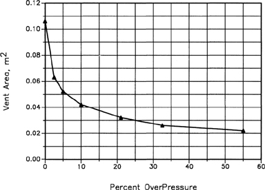
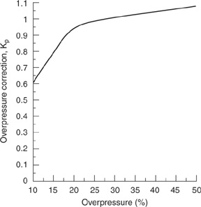
In chapter 8 we showed that for liquids and two-phase relief, the relieving process begins at the relief set pressure with the pressure normally continuing to rise past the set pressure (see curve B in Figure 8-2). These overpressures frequently exceed the set pressure by 25% or more. A relief device designed to maintain the pressure at the set pressure could require an excessively large vent area. As shown in Figure 9-1, the relief vent area is reduced substantially as the over-pressure increases. This is one example that illustrates this typical result. The optimal vent area for a particular relief depends on the specific application. The overpressure specification is part of the relief design. Normally, relief devices are specified for overpressures from 10% to 25%, depending on the requirements of the equipment protected and the type of material relieved.
Figure 9-1 Required vent area as a function of overpressure for two-phase flow. The Vent Area is Decreased Appreciably as the Overpressure Increases. Data From J. C. Leung, “Simplified Vent Sizing Equations for Emergency Relief Requirements in Reactors and Storage Vessels,” AICHE Journal (1986), 32(10).
Spring relief devices require 25–30% of maximum flow capacity to maintain the valve seat in the open position. Lower flows result in “chattering,” caused by rapid opening and closing of the valve disc. This can lead to destruction of the relief device and a dangerous situation. A relief device with an area that is too large for the required flow may chatter. For this reason reliefs must be designed with the proper vent area, neither too small nor too large.
Experimental data at the actual relief conditions are recommended for sizing relief vents for runaway reaction scenarios. As always, manufacturers’ technical specifications are used for selection, purchase, and installation.
In this chapter we present methods for calculating the relief device vent areas for the following configurations:
• conventional spring-operated reliefs in liquid or vapor-gas service,
• rupture discs in liquid or vapor-gas service,
• two-phase flow during runaway reactor relief,
• reliefs for dust and vapor explosions,
• reliefs for fires external to process vessels, and
• reliefs for thermal expansion of process fluids.
9-1 Conventional Spring-Operated Reliefs in Liquid Service
Flow through spring-type reliefs is approximated as flow through an orifice. An equation representing this flow is derived from the mechanical energy balance (Equation 4-1). The result is similiar to Equation 4-6, except that the pressure is represented by a pressure difference across the spring relief:
(9-1)
![]()
where
![]() the liquid velocity through the spring relief,
the liquid velocity through the spring relief,
Co is the discharge coefficient,
ΔP is the pressure drop across the relief, and
ρ is the liquid density.
The volumetric flow Qv of liquid is the product of the velocity times the area, or ![]() Substitut-ing Equation 9-1 and solving for the vent area A of the relief, we obtain
Substitut-ing Equation 9-1 and solving for the vent area A of the relief, we obtain
(9-2)
![]()
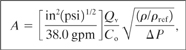
A working equation with fixed units is derived from Equation 9-2 by (1) replacing the density ρ with the specific gravity (ρ/ρref) and (2) making the appropriate substitutions for the unit conversions. The result is
(9-3)
where
A is the computed relief area (in2),
Qv is the volumetric flow through the relief (gpm),
Co is the discharge coefficient (unitless),
(ρ/ρref) is the specific gravity of the liquid (unitless), and
ΔP is the pressure drop across the spring relief (lbf/in2).
In reality, flow through a spring-type relief is different from flow through an orifice. As the pressure increases, the relief spring is compressed, increasing the discharge area and increasing the flow. A true orifice has a fixed area. Also, Equation 9-3 does not consider the viscosity of the fluid. Many process fluids have high viscosities. The relief vent area must increase as the fluid viscosity increases. Finally, Equation 9-3 does not consider the special case of a balanced-bellows-type relief.
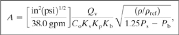
Equation 9-3 has been modified by the American Petroleum Institute to include corrections for the above situations. The result1 is
1API RP 520, Recommended Practice for the Sizing, Selection, and Installation of Pressure Relieving Systems in Refineries, 6th ed. (Washington, DC: American Petroleum Institute, 1993).
(9-4)
where
A is the computed relief area (in2),
Qv is the volumetric flow through the relief (gpm),
Co is the discharge coefficient (unitless),
Kv is the viscosity correction (unitless),
Kp is the overpressure correction (unitless),
Kb is the backpressure correction (unitless),
(ρ/ρref) is the specific gravity of the liquid (unitless),
Ps is the gauge set pressure (lbf/in2), and
Pb is the gauge backpressure (lbf/in2).
Note that the ΔP term in Equation 9-3 has been replaced by a term involving the difference between the set pressure and the backpressure. Equation 9-4 appears to assume a maximum pressure equal to 1.25 times the set pressure. Discharge at other maximum pressures is accounted for in the overpressure correction term Kb.
Cois the discharge coefficient. Specific guidelines for the selection of an appropriate value are given in chapter 4, section 4-2. If this value is uncertain, a conservative value of 0.61 is used to maximize the relief vent area.
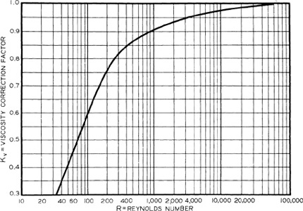
The viscosity correction Kv corrects for the additional frictional losses resulting from flow of high-viscosity material through the valve. This correction is given in Figure 9-2. The required relief vent area becomes larger as the viscosity of the liquid increases (lower Reynolds numbers). Because the Reynolds number is required to determine the viscosity correction and because the vent area is required to calculate the Reynolds number, the procedure is iterative. For most reliefs the Reynolds number is greater than 5000 and the correction is near 1. This assumption is frequently used as an initial estimate to begin the calculations.
Figure 9-2 Viscosity Correction Factor Kv for Conventional Reliefs in Liquid Service. Source: API RP 520, Recommended Practice for the Sizing, Selection, and Installation of Pressure-Relieving Systems in Refineries, 6th ed. (1993), p. 35. Used by Permission of the American Petroleum Institute, Washington, DC.
Darby and Molavi2 developed an equation to represent the viscosity correction factor shown in Figure 9-2. This equation applies only to Reynolds numbers greater than 100:
2R. Darby and K. Molavi, “Viscosity Correction Factor for Safety Relief Valves,” Process Safety Progress(1997), 16(2).
(9-5)
![]()
where
Kv is the viscosity correction factor(unitless)and
Re is the Reynolds number(unitless).
The overpressure correction Kp includes the effect of discharge pressures greater than the set pressure. This correction is given in Figure 9-3. The overpressure correction Kp is a function of the overpressure specified for the design. As the specified overpressure becomes smaller, the correction value decreases, resulting in a larger relief area. Designs incorporating less than 10% overpressure are not recommended. The overpressure correction factor curve shown in Figure 9-3 shows that up to and including 25% overpressure, the relief device capacity is affected by the changing discharge area as the valve lifts, the change in the orifice discharge coefficient, and the change in overpressure. Above 25% the valve capacity is affected only by the change in overpressure because the valve discharge area is constant and behaves as a true orifice. Valves operating at low overpressures tend to chatter, so overpressures less than 10% should be avoided.
Figure 9-3 Overpressure correction Kp for Spring-Operated Reliefs in Liquid Service. Source: API RP 520, Recommended Practice for the Sizing, Selection, and Installation of Pressure-Relieving Systems in Refineries, 6th ed. (1993), p. 37. Used by Permission of the American Petroleum Institute, Washington, DC.
The backpressure correction Kb is used only for balanced-bellows-type spring reliefs and is given in Figure 9-4. This correction compensates for the absence of backpressure on the back of the relief vent disc.
Figure 9-4 Backpressure correction Kbfor 25% Overpressure on Balanced-Bellows Reliefs in Liquid Service. Source: API RP 520, Recommended Practice for the Sizing, Selection, and Installation of Pressure Relieving Systems in Refineries, 6th ed. (1993), p.35. Used by permission of the American Petroleum Institute, Washington, DC.

Example 9-1
A positive displacement pump pumps water at 200 gpm at a pressure of 200 psig. Because a dead-headed pump can be easily damaged, compute the area required to relieve the pump, assuming a backpressure of 20 psig and (a) a 10% overpressure and (b) a 25% overpressure.
Solution.
a. The set pressure is 200 psig. The backpressure is specified as 20 psig and the overpressure is 10% of the set pressure, or 20 psig.
The discharge coefficient Co is not specified. However, for a conservative estimate a value of 0.61 is used.
The quantity of material relieved is the total flow of water; so Qv =200gpm.
The Reynolds number through the relief device is not known. However, at 200 gpm the Reynolds number is assumed to be greater than 5000. Thus the viscosity correction is, from Figure 9-2, Kv 1.0.
The overpressure correction Kp is given in Figure 9-3. Because the percentage of over-pressure is 10%, from Figure 9-3, Kp 0.6.
The backpressure correction is not required because this is not a balanced-bellows spring relief. Thus Kb = 1.0.
These numbers are substituted directly into Equation 9-4:
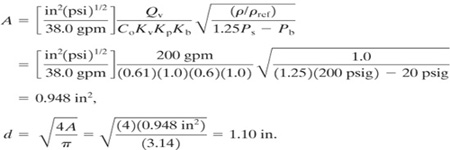
b. For an overpressure of 25%, Kp 1.0 (Figure 9-3), and
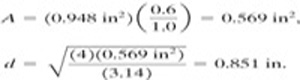
As expected, the relief vent area decreases as the overpressure increases.
Manufacturers do not provide relief devices to the nearest 0.01 in. Thus a selection must be made depending on relief device sizes available commercially. The next largest available size is normally selected. For all relief devices the manufacturers’ technical specifications must be checked before selection and installation.
9-2 Conventional Spring-Operated Reliefs in Vapor or Gas Service
For most vapor discharges through spring reliefs the flow is critical. However, the downstream pressure must be checked to ensure that it is less than the choked pressure computed using Equation 4-49. Thus for an ideal gas Equation 4-50 is valid:
(4-50)
![]()
where
(Qm)choked is the discharge mass flow,
Co is the discharge coefficient,
A is the area of the discharge,
P is the absolute upstream pressure,
γ is the heat capacity ratio for the gas,
gcis the gravitational constant,
M is the molecular weight of the gas,
Rg is the ideal gas constant, and
T is the absolute temperature of the discharge.
Equation 4-50 is solved for the area of the relief vent given a specified mass flow rate Qm:
(9-6)
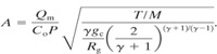
Equation 9-6 is simplified by defining a function χ:
(9-7)

Then the required relief vent area for an ideal gas is computed using a simplified form of Equation 9-6:
(9-8)
![]()
For nonideal gases and real vents Equation 9-8 is modified by (1) including the compressibility factor z to represent a nonideal gas and (2) including a backpressure correction Kb. The result is
(9-9)

where
A is the area of the relief vent,
Qm is the discharge flow,
Co is the effective discharge coefficient, usually 0.975 (unitless),
Kb is the backpressure correction (unitless),
P is the maximum absolute discharge pressure,
T is the absolute temperature,
z is the compressibility factor (unitless), and
M is the average molecular weight of the discharge material.
The constant X is represented by Equation 9-7. It is conveniently calculated using the following fixed-unit expression:
(9-10)
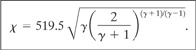
If Equation 9-10 is used, Equation 9-9 must have the following fixed units: Qm in lbm/hr, P in psia, T in °R, and M in lbm/lb-mol. The area computed is in in2.
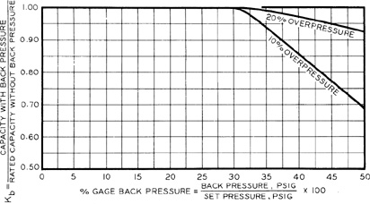
Kb is the backpressure correction and depends on the type of relief used. Values are given in Figure 9-5 for conventional spring reliefs and in Figure 9-6 for balanced-bellows reliefs.
Figure 9-5 Backpressure correction Kb for conventional spring-type reliefs in vapor or gas service. Source: API RP 520, Recommended Practice for the Sizing, Selection, and Installation of Pressure-Relieving Systems in Refineries, 6th ed. (1993), p. 33. Used by permission of the American Petroleum Institute, Washington, DC.
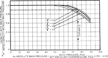
Figure 9-6 Backpressure correction Kb for balanced-bellows reliefs in vapor or gas service. Source: API RP 520, Recommended Practice for the Sizing, Selection, and Installation of Pressure-Relieving Systems in Refineries, 6th ed. (1993), p. 29. Used by permission of the American Petroleum Institute, Washington, DC.
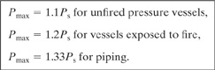
The pressure used in Equation 9-9 is the maximum absolute relieving pressure. It is given for the fixed-unit case by,
(9-11)
P = Pmax + 14.7,
where Pmax is the maximum gauge pressure in psig. For vapor reliefs the following guidelines are recommended3:
3ASME Boiler and Pressure Vessel Code (New York: American Society of Mechanical Engineers, 1998).
(9-12)
For vapor flows that are not choked by sonic flow the area is determined using Equation 4-48. The downstream pressure P is now required, and the discharge coefficient Co must be estimated. The API Pressure Vessel Code4 provides working equations that are equivalent to Equation 4-48.
4API RP 520, Recommended Practice.
Example 9-2
A nitrogen regulator fails and allows nitrogen to enter a reactor through a 6-in-diameter line. The source of the nitrogen is at 70°F and 150 psig. The reactor relief is set at 50 psig. Determine the diameter of a balanced-bellows spring-type vapor relief required to protect the reactor from this incident. Assume a relief backpressure of 20 psig.
Solution
The nitrogen source is at 150 psig. If the regulator fails, the nitrogen will flood the reactor, increasing the pressure to a point where the vessel will fail. A relief vent must be installed to vent the nitrogen as fast as it is supplied through the 6-in line. Because no other information on the piping system is provided, the flow from the pipe is initially assumed to be represented by critical flow through an orifice. Equation 4-50 describes this:
![]()
First, however, the choked pressure across the pipe must be determined to ensure critical flow. For diatomic gases the choked pressure is given as (see chapter 4)
Pchoked = 0.528P = (0.528)(150 + 14.7) = 87.0 psia.
The maximum relief design pressure within the reactor during the relief venting is, from Equation 9-12,
Pmax = 1.1Ps = (1.1)(50 psig) = 55.0 psig = 69.7 psia.
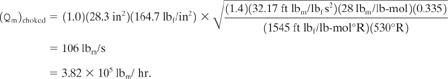
This is a 10% overpressure. Thus the pressure in the reactor is less than the choked pressure, and the flow from the 6-in line will be critical. The required quantities for Equation 4-50 are
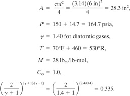
Substituting into Equation 4-50, we obtain
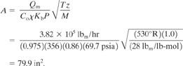
The area of the relief vent is computed using Equations 9-9 and 9-10 with a backpressure correction Kb determined from Figure 9-6. The backpressure is 20 psig. Thus
![]()
From Figure 9-6, Kb = 0.86 for an overpressure of 10%. The effective discharge coefficient is assumed to be 0.975. The gas compressibility factor z is approximately 1 at these pressures. The pressure P is the maximum absolute pressure. Thus P 69.7 psia. The constant X is computed from Equation 9-10:
![]()
The required vent area is computed using Equation 9-9:
The required vent diameter is
![]()
Manufacturers provide relief devices only at convenient sizes. The next largest diameter closest to the one required is selected. This would likely be 10![]() in (10.125 in).
in (10.125 in).
9-3 Rupture Disc Reliefs in Liquid Service
For liquid reliefs through rupture discs without significant lengths of downstream piping the flow is represented by Equation 9-2 or by Equation 9-3 for flow through a sharp-edged orifice. No corrections are suggested.
Equations 9-2 and 9-3 apply to rupture discs discharging directly to the atmosphere. For rupture discs discharging into a relief system (which might include knockout drums, scrub-bers, or flares), the rupture disc is considered a flow restriction, and the flow through the entire pipe system must be considered. The calculation is performed identically to regular pipe flow (see chapter 4). The calculation to determine the rupture disc area is iterative for this case. Isaacs5 recommended assuming that the rupture disc is equivalent to 50 pipe diameters in the calculation.
5Marx Isaacs, ‘Pressure Relief Systems,’ Chemical Engineering (Feb. 22, 1971), p. 113.
9-4 Rupture Disc Reliefs in Vapor or Gas Service
Flow of vapor through rupture discs is described using an orifice equation similar to Equation 9-9 but without the additional correction factors. The result is
(9-13)

Equation 9-13 assumes a discharge coefficient Co of 1.0.
If appreciable backpressures exist from downstream relief systems, a procedure similar to the procedure used for liquid reliefs through rupture discs is required. The procedure is iterative.
Example 9-3
Determine the diameter of a rupture disc required to relieve the pump of Example 9-1, part a.
Solution
The pressure drop across the rupture disc is
Δp = pmax - pb = 220 psig - 20 psing = 200psig.
The specific gravity of the water (p/pref) is 1.0. A conservative discharge coefficient of 0.61 is assumed. Substituting into Equation 9-3, we obtain
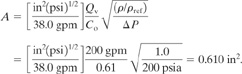
The relief vent diameter is
![]()
This compares to a spring relief vent area of 1.10 in.
Example 9-4
Compute the rupture disc vent diameter required to relieve the process of Example 9-2.
Solution
The solution is provided by Equation 9-9. The solution is identical to Example 9-2, with the exception of a deletion of the correction factor Kb. The area is therefore
A = (79.9 in2)(0.86) = 68.7 in2
The rupture disc diameter is
![]()
This compares to a spring relief diameter of 9.32 in.
9-5 Two-Phase Flow during Runaway Reaction Relief
When a runaway reaction occurs within a reactor vessel, two-phase flow should be expected during the relief process. The vent sizing package (VSP) laboratory apparatus described in chapter 8 provides the much needed temperature and pressure rise data for relief area sizing.
Figure 9-7 A tempered reaction system showing the important energy terms. The heat losses through the reactor walls are assumed negligible.
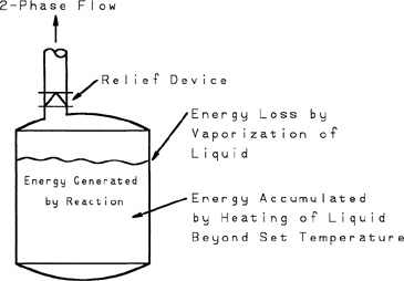
Figure 9-7 shows the most common type of reactor system, called a tempered reactor. It is called “tempered” because the reactor contains a volatile liquid that vaporizes or flashes during the relieving process. This vaporization removes energy by means of the heat of vaporization and tempers the rate of temperature rise resulting from the exothermic reaction.
The runaway reactor is treated as entirely adiabatic. The energy terms include (1) energy accumulation resulting from the sensible heat of the reactor fluid as a result of its increased temperature due to overpressure and (2) the energy removal resulting from the vaporization of liquid in the reactor and subsequent discharge through the relief vent.
The first step in the relief sizing calculation for two-phase vents is to determine the mass flux through the relief. This is computed using Equation 4-104, representing choked two-phase flow through a hole:
(4-104)
![]()
where, for this case,
Qm is the mass flow through the relief,
ΔHV is the heat of vaporization of the fluid,
A is the area of the hole,
vfg is the change of specific volume of the flashing liquid,
CP is the heat capacity of the fluid, and
Ts is the absolute saturation temperature of the fluid at the set pressure.
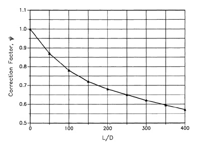
Figure 9-8 Correction factor Ψ correcting for two-phase flashing flow through pipes. Data from J. C. Leung and M. A. Grolmes, “The Discharge of Two-Phase Flashing Flow in a Horizontal Duct,” AICHE Journal (1987), 33(3): 524—527.
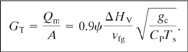
The mass flux GT is given by
![]()
Equation 9-14 applies to two-phase relief through a hole. For two-phase flow through pipes an overall dimensionless discharge coefficient Ψ is applied. Equation 9-14 is the so-called equilibrium rate model (ERM) for low-quality choked flow.6 Leung7 showed that Equation 9-14 must be multiplied by a factor 0.9 to bring the value in line with the classic homogeneous equilibrium model (HEM). The result should be generally applicable to homogeneous venting of a reactor (low quality, not restricted to just liquid inlet condition):
6H. K. Fauske, “Flashing Flows or: Some Practical Guidelines for Emergency Releases,” Plant Operations Progress (July 1985), 4(3).
7J. C. Leung, “Simplified Vent Sizing Equations for Emergency Relief Requirements in Reactors and Storage Vessels,” AICHE Journal (1986), 32(10): 1622.
(9-15)
Values for Ψ are provided in Figure 9-8. For a pipe of length 0, Ψ1. As the pipe length increases, the value of Ψdecreases.
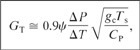
A somewhat more convenient expression is derived by rearranging Equation 4-102 to yield
(9-16)
![]()
and substituting into Equation 9-15, we obtain
(9-17)
![]()
The exact derivative is approximated by a finite-difference derivative to yield
(9-18)
where
ΔP is the overpressure and
ΔT is temperature rise corresponding to the overpressure.
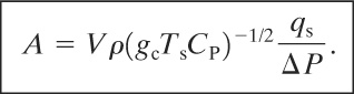
The required vent area is computed by solving a particular form of the dynamic energy balance. Details are provided elsewhere.8 The result is
8J. C. Leung, “Simplified Vent Sizing.
(9-19)

An alternative form is derived by applying Equation 4-102:
(9-20)
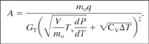
For Equation 9-19 and 9-20 the following additional variables are defined:
mois the total mass contained within the reactor vessel before relief,
q is the exothermic heat release rate per unit mass,
V is the volume of the vessel, and
CV is the liquid heat capacity at constant volume.
For both Equations 9-19 and 9-20 the relief area is based on the total heat added to the system (numerator) and the heat removed or absorbed (denominator). The first term in the denominator corresponds to the net heat removed by the liquid and vapor leaving the system; the second term corresponds to the heat absorbed as a result of increasing the temperature of the liquid because of the overpressure.
The heat input q resulting from an exothermic reaction is determined using fundamental kinetic information or from the DIERS VSP (see chapter 8). For data obtained using the VSP, the equation
(9-21)
![]()
is applied, where the derivative, denoted by the subscript s, corresponds to the heating rate at the set pressure and the derivative, denoted by the subscript m, corresponds to the temperature rise at the maximum turnaround pressure. Both derivatives are determined experimentally using the VSP.
The equations assume that
1. uniform froth or homogeneous vessel venting occurs,
2. the mass flux GT varies little during the relief,
3. the reaction energy per unit mass q is treated as a constant,
4. physical properties CV, ΔHV, and vfg are constant, and
5. the system is a tempered reactor system. This applies to most reaction systems.
Units are a particular problem when using the two-phase equations. The best procedure is to convert all energy units to their mechanical equivalents before solving for the relief area, particularly when English engineering units are used.
Example 9-5
Leung9 reported on the data of Huff10 involving a 3500-gal reactor with styrene monomer undergoing adiabatic polymerization after being heated inadvertently to 70°C. The maximum allowable working pressure (MAWP) of the vessel is 5 bar. Given the following data, determine the relief vent diameter required. Assume a set pressure of 4.5 bar and a maximum pressure of 5.4 bar absolute:
9Leung, “Simplified Vent Sizing.”
10J. E. Huff, “Emergency Venting Requirements,” Plant/Operations Progress (1982), 1(4): 211.
Data
Volume (V): 3500 gal=13.16 m3
Reaction mass (mo): 9500 kg
Set temperature (Ts): 209.4°C=482.5 K
Data from VSP
Maximum temperature (Tm): 219.5°C 492.7 K
(dT/dt)s 29.6°C/min 0.493 K/s
(dT/dt)m 39.7°C/min 0.662 K/s
Physical Property Data
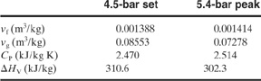
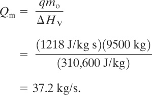
Solution
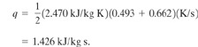
The heating rate q is determined using Equation 9-21:
(9-21)
![]()
Assuming that CV=CP, we have
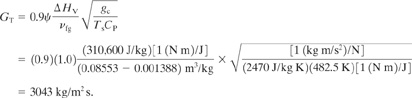
The mass flux is given by Equation 9—15. Assuming L/D=0, Ψ 1.0:
The relief vent area is determined from Equation 9–19. The change in temperature ΔT is Tm—Ts= 492.7–482.5 = 10.2K:

The required relief diameter is
![]()
Suppose that all vapor relief was assumed. The size of the required vapor phase rupture disc is determined by assuming that all the heat energy is absorbed by the vaporization of the liquid. At the set temperature the heat release rate q is
![]()
The vapor mass flow through the relief is then
Equation 9-6 provides the required relief area. The molecular weight of styrene is 104. Assume that γ = 1.32 and Co = 1.0. Then
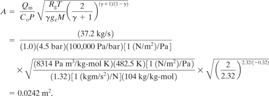
This requires a relief device with a diameter of 0.176 m, a significantly smaller diameter than for two-phase flow. Thus, if the relief were sized assuming all vapor relief, the result would be physically incorrect and the reactor would be severely tested during this runaway event.
Simplified Nomograph Method
Fauske11 developed a simplified chart-driven approach to the two-phase reactor relief problem. He suggested the following equation for determining the relief area:
11Hans K. Fauske, “A Quick Approach to Reactor Vent Sizing,” Plant/Operations Progress (1984), 3(3), and “Generalized Vent Sizing Nomogram for Runaway Chemical Reactions,” Plant/Operations Progress (1984), 3(4).
(9-22)
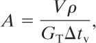
where
A is the relief vent area,
V is the reactor volume,
p is the density of the reactants,
GT is the mass flux through the relief, and
Δtv is the venting time.
Equation 9-22 was developed by Boyle12 by defining the required vent area as the size that would empty the reactor before the pressure could rise above some allowable overpressure for a given vessel.
12W. J. Boyle Jr., “Sizing Relief Area for Polymerization Reactors,” Chemical Engineering Progress (August 1967), 63(8): 61.
The mass flux GT is given by Equation 9-15 or 9-18, and the venting time is given approximately by
(9-23)
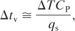
where
ΔT is the temperature increase corresponding to the overpressure ΔP,
T is the temperature,
CP is the heat capacity, and
qs is the energy release rate per unit mass at the set pressure of the relief system.
Combining Equations 9-22, 9-14, and 9-23 yields
(9-24)
Equation 9-24 provides a conservative estimate of the required vent area. By considering the case of 20% absolute overpressure, assuming a typical liquid heat capacity of 2510 J/kg K for most organic materials, and assuming a saturated water relationship, we can obtain the following equation13:
13J. C. Leung and H. K. Fauske, “Runaway System Characterization and Vent Sizing Based on DIERS Methodology,” Plant/Operations Progress (April 1987), 6(2).
(9-25)
Figure 9-9 Nomograph for sizing two-phase reactor reliefs. Source: H. K. Fauske, “Generalized Vent Sizing Nomogram for Runaway Chemical Reactions,” Plant/Operations Progress (1984), 3(4). Used by permission of the American Institute of Chemical Engineers.

A simple nomograph of the results can be plotted and is shown in Figure 9-9. The required vent area is determined simply from the heating rate, the set pressure, and the mass of reactants.
The Fauske nomograph is useful for performing quick estimates and for checking the results of the more rigorous computation.
Recent studies14 suggest that the nomograph data of Figure 9-9 apply for a discharge coefficient of ψ = 0.5, representing a discharge (L/D) of 400. Use of the nomograph at other discharge pipe lengths and different ψ requires a suitable correction, as shown in the following example.
14H. G. Fisher and J. C. Leung, personal communication, January 1989.
Example 9-6
Estimate the relief vent area using the Fauske nomograph approach for the reaction system of Example 9-5.
Solution
The heating rate at the set temperature is specified as 29.6°C/min. The set pressure is 4.5 bar absolute, so
Ps (14.5 bar)(0.9869 bar/atm)(14.7 psia/atm) = 65.3 psia.
From Figure 9-9 the vent area required per 1000 kg of reactant is about 1.03 X 10⁻²m2. Thus the total relief area is
Figure 9-9 is applicable for ψ = 0.5. For ψ = 1.0 the area is adjusted linearly:

This assumes a 20% absolute overpressure. The result can be adjusted for other overpressures by multiplying the area by a ratio of 20/(new absolute percentage of overpressure).
This result compares to a more rigorously computed area of 0.084 m2.
Two-phase flow through reliefs is much more complex than the introduction provided here. Furthermore, the technology is still undergoing substantial development. The equations presented here are not universally applicable; however, they do represent the most accepted method available today.
9-6 Deflagration Venting for Dust and Vapor Explosions
Loss prevention means preventing the existence of hazards. However, for some situations hazards are unavoidable. For example, during the milling process to make flour from wheat, substantial quantities of flammable dust are produced. An uncontrolled dust explosion in a warehouse, storage bin, or processing unit can eject high-velocity structural debris over a considerable area, propagating the accident and resulting in increased injuries. Deflagration venting reduces the impact of dust and vapor cloud explosions by controlling the release of the explosion energy. The energy of the explosion is directed away from plant personnel and equipment.
Deflagration venting in buildings and process vessels is usually achieved by using blowout panels, as shown in Figure 9-10. The blowout panel is designed to have less strength than the walls of the structure. Thus, during an explosion, the blowout panels are preferentially detached and the explosive energy is vented. Damage to the remaining structure and equipment is minimized. For particularly explosive dusts or vapors, it is not unusual for the walls (and perhaps roof) of the entire structure to be constructed of blowout panels.
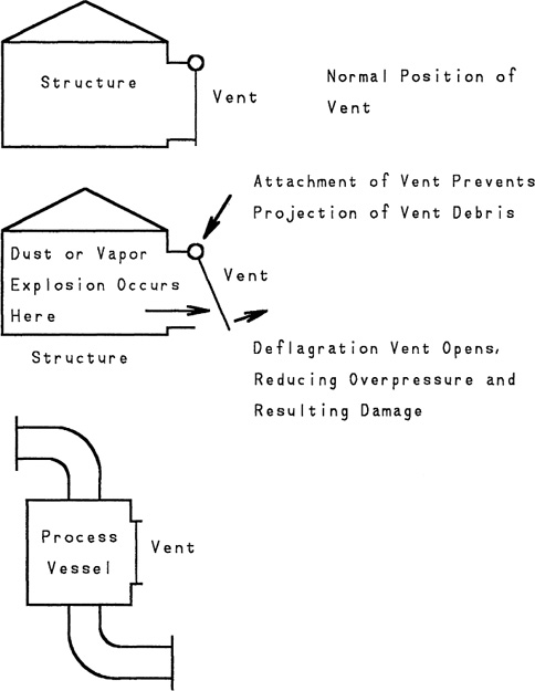
Figure 9-10 Deflagration vents for structures and process vessels.
The actual construction details of blowout panels is beyond the scope of the text. A detached blowout panel moving at high velocity can cause considerable damage. Therefore a mechanism must be provided to retain the panel during the deflagration process. Furthermore, thermal insulation of panels is also required. Construction details are available in manufacturers’ literature.
Blowout panels are designed to provide the proper relief area, depending on a number of design factors. These include the explosive behavior of the dust or vapor, the maximum overpressure allowable in the structure, and the volume of the structure. Design standards are available.15
15NFPA 68, Guide for Venting of Deflagrations (Quincy, MA: National Fire Protection Association, 1998)
Deflagration design is segregated into two categories: low-pressure and high-pressure structures. Low-pressure structures include structures with sheet metal sides and other low-strength building materials. These structures are capable of withstanding not more than 1.5 psig (0.1 bar gauge). High-pressure structures include steel process vessels, concrete buildings, and so forth that are capable of withstanding pressures greater than 1.5 psig (0.1 bar gauge).
Vents for Low-Pressure Structures
For low-pressure structures that are capable of withstanding pressures of not more than 1.5 psi (0.1 bar gauge), original design techniques were based on the Runes (pronounced Rooness) equation16:
16Richard R. Schwab, “Recent Developments in Deflagration Venting Design,” in Proceedings of the International Symposium on Preventing Major Chemical Accidents, John L. Woodward, ed. (New York: American Institute of Chemical Engineers, 1987), p. 3.101.
(9-26)
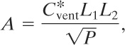
where
A is the required vent area,
![]() is a constant that depends on the nature of the combustible material,
is a constant that depends on the nature of the combustible material,
L1 is the smallest dimension of the rectangular building structure to be vented,
L2 is the second smallest dimension of the enclosure to be vented, and
P is the maximum internal pressure that can be withstood by the weakest member of the enclosure.
Swift and Epstein17 presented a more detailed equation, including many important combustion features: (9-27)
17Ian Swift and Mike Epstein, “Performance of Low Pressure Explosion Vents,” Plant/Operations Progress (April 1987), 6(2).
(9-27)
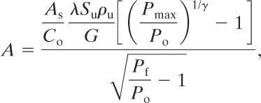
where
A is the required vent area,
As is the inside surface area of the enclosure,
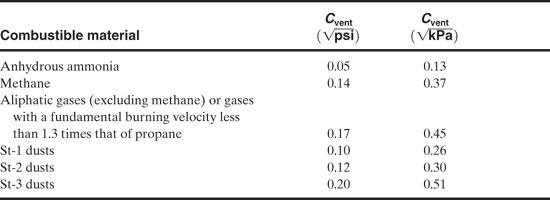
Table 9-1 Combustible Characteristic Constant for the Swift-Epstein Equation1
1NFPA, Venting of Deflagrations (Quincy, MA: National Fire Protection Association, 1998).
Co is the discharge coefficient,
λ is the turbulent augmentation factor,
Su is the laminar burning velocity,
pu is the density of the unburned gas,
G is the mass flux,
Pmax is the maximum unvented explosion pressure,
Po is the initial pressure,
Pf is the final peak pressure during the vent, and
γ is the heat capacity ratio.
Many of the variables in Equation 9-27 can be estimated or assumed. These variables are regrouped to result in the following form:
(9-28)
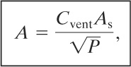
where P is the maximum internal overpressure that can be withstood by the weakest structural element. Equation 9-28 is remarkably similar to the Runes equation (Equation 9-26).
Values for the constant Cvent are given in Table 9-1.
Example 9-7
A room is used for dispensing flammable liquids. The liquids are expected to have fundamental burning velocities less than 1.3 times that of propane. The room is 9 m long by 6 m wide by 6 m in height. Three of the walls are shared with an adjoining structure. The fourth and larger wall of the room is on the outer surface of the structure. The three inside walls are capable of withstanding a pressure of 0.05 bar. Estimate the vent area required for this operation.
Solution
The vent must be installed on the larger outer wall to vent the combustion away from the adjoining structure. The venting constant for this flammable vapor is provided in Table 9-1 and has a value of 0.45 ![]() . Equation 9-28 is used to estimate the required vent area. The total surface area of the room (including floor and ceiling) is
. Equation 9-28 is used to estimate the required vent area. The total surface area of the room (including floor and ceiling) is
![]()
The required vent area is
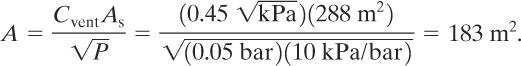
This is larger than the area of the outer wall. One option is to strengthen the three inner walls to withstand a higher pressure. This would reduce the vent area required.
Vents for High-Pressure Structures
High-pressure structures are capable of withstanding pressures of more than 1.5 psig (0.1 bar gauge). The vent design is based on the definition of a deflagration index for gases or dusts:
(9-29)
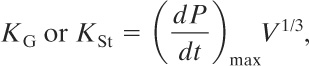
where
KG is the deflagration index for gases and vapors,
KSt is the deflagration index for dusts,
(dP/dt)max is the maximum pressure increase, determined experimentally, and
V is the volume of the vessel.
We discussed the experimental procedure used to determine the deflagration indexes for gases and dusts in chapter 6. Tables of typical values were also provided.
Extensive testing with dusts and vapors has resulted in a detailed set of empirical equations for the relief vent area (published as NFPA 68).18 The length-to-diameter ratio L/D of the enclosure determines the equation(s) used for calculating the necessary vent area. For noncircular enclosures the value used for the diameter is the equivalent diameter given by D = 2![]() , where A is the cross-sectional area normal to the longitudinal axis of the space.
, where A is the cross-sectional area normal to the longitudinal axis of the space.
18NFPA 68, Guide for Venting of Deflagrations (Quincy, MA: National Fire Protection Association, 1998).
For combusting vapors discharging through a low inertial vent and an enclosure L/D of less than 2, the following equation from NFPA 68 applies:
(9-30)
![]()
where
Av is the vent area (m2),
KG is the vapor deflagration index (bar-m/s),
Pred is the maximum pressure during venting (bar gauge), and
Pstat is the vent release pressure (bar gauge).
Equation 9-30 has the following restrictions on its use:
• KG is less than 550 bar-m/s,
• Pstat is less than 0.5 bar,
• Pred is less than 2 bars, and
• V is less than 1000 m3.
The experimental conditions under which Equation 9-30 was developed are as follows:
• vessel volumes of 2.4, 10, 25, and 250 m3 with an L/D for all test vessels of approximately 1,
• initial pressure atmospheric,
• ignition energy of 10 J,
• quiescent gas mixture at time of ignition with no turbulence inducers, and
• P stat ranging from 0.1 bar gauge to 0.5 bar.
For enclosures with L/D ranging from 2 to 5 the area calculated using Equation 9-30 is adjusted using (9-31)
(9-31)
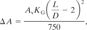
where
ΔA is the adjustment to the vent area of Equation 9-30 (m2),
KG is the deflagration index for the combusting gas (bar-m/s), and
L/D is the length to diameter ratio of the enclosure (unitless).
For L/D values greater than 5, NFPA 68 must be consulted.
For venting of combustible dusts through a low inertial vent and an enclosure L/D of less than 2, the following equation from NFPA 68 applies:
(9-32)
![]()
where
Av is the vent area (m2),
Pmax is the maximum pressure reached during deflagration of an optimum mixture of combustible dust and air in a closed vessel (bar gauge),
KSt is the dust deflagration index (bar-m/s),
Pred is the maximum pressure during venting (bar gauge),
Pstat is the vent release pressure (bar gauge), and
V is the volume of the enclosure (m3).
The following limitations apply to Equation 9-32:
• for KSt between 10 and 300 bar-m/s, Pmax must be between 5 and 10 bars gauge,
• for KSt between 300 and 800 bar-m/s, Pmax must be between 5 and 12 bars gauge,
• Pstat must be between 0.1 and 1 bar gauge,
• Pred must be between 0.1 and 2 bars gauge,
• the enclosure volume must be between 0.1 and 10,000 m3.
For L/D values equal to or greater than 2 but less than 6 and for Pred less than 1.5 bars gauge (22 psi), the vent area of Equation 9-32 is increased by,
(9-33)
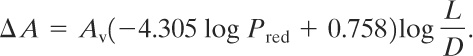
The adjusted vent area (Equation 9-33) is sensitive to Pred. For low values of Pred the additional vent area is large. For Pred values of 1.5 bars gauge and higher Equation 9-32 should be used alone. For long pipes and ducts where L/D is greater than 6, NFPA 68 must be consulted.
Example 9-8
Consider again the flammable liquid dispensing room of Example 9-7. In this case the walls have been reinforced to withstand a pressure of 0.4 bar (Pred). Assume that the vent will operate at 0.2 bar (Pstat) and that the KG of the vapor is 100 bar-m/s. Estimate the vent area required to protect this enclosure.
Solution
The L/D ratio must first be determined for this enclosure. The longitudinal axis runs the 9 m length of the room. The cross-sectional area normal to this axis is (6 m)(6 m) = 36 m2. Thus D = 2![]() = 6.77 m. Then L/D = 9 m/6.77 m 1.3, and it follows that Equation 9-30 applies without further correction. The volume of the enclosure is (9 m)(6 m)(6 m) = 324 m3. Substituting into Equation 9-30, we obtain
= 6.77 m. Then L/D = 9 m/6.77 m 1.3, and it follows that Equation 9-30 applies without further correction. The volume of the enclosure is (9 m)(6 m)(6 m) = 324 m3. Substituting into Equation 9-30, we obtain

More than adequate area exists on the outer wall of the enclosure to accommodate this vent.
Both vent sizing methods for gases and dusts require values for the deflagration indexes, KG or KSt. We discussed the experimental procedure to determine these values and also provided tables of typical values for gases and dusts in chapter 6.
9-7 Venting for Fires External to Process Vessels
Fires external to process vessels can result in heating and boiling of process liquids, as shown in Figure 9-11. Venting is required to prevent explosion of these vessels.
Two-phase flow during these reliefs is possible but not likely. For runaway reactor reliefs the energy is generated by reaction throughout the entire reactor liquid contents. For heating caused by external fire the heating occurs only at the surface of the vessel. Thus liquid boiling will occur only next to the wall, and the resulting two-phase foam or froth at the liquid surface will not have a substantial thickness. Two-phase flow during fire relief can therefore be prevented by providing a suitable vapor space above the liquid within the vessel.
Figure 9-11 Heating of a process vessel as a result of an external fire. Venting is required to prevent vessel rupture. For most fires only a fraction of the external vessel is exposed to fire.

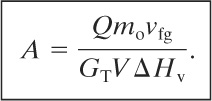
Two-phase fire relief equations are available for conservative design. Leung19 presented an equation for the maximum temperature based on an energy balance around the heated vessel. This assumes a constant heat input rate Q:
19Leung, “Simplified Vent Sizing Equations.”
(9-34)
![]()
where
Tm is the maximum temperature in the vessel,
Ts is the set temperature corresponding to the set pressure,
Q is the constant heat input rate,
GT is the mass flux through the relief,
A is the area of the relief,
CV is the heat capacity at constant volume,
mo is the liquid mass in the vessel,
V is the volume of the vessel,
vfg is the volume difference between the vapor and liquid phases, and
ΔHv is the heat of vaporization of the liquid.
The solution to Equation 9-34 for GTA is done by an iterative or trial-and-error technique. Equation 9-34 is likely to produce multiple roots. In this case the correct solution is the minimum mass flux GT. For the special case of no overpressure, Tm = Ts, and Equation 9-34 reduces to
(9-35)
Various relationships have been recommended for computing the heat added to a vessel that is engulfed in fire. For regulated materials the OSHA 1910.106 criterion20 is mandatory. Other standards are also available.21 Crozier,22 after analysis of the various standards, recommended the following equations for determining the total heat input Q:
20OSHA 1910.106, Flammable and Combustible Liquids (Washington, DC: US Department of Labor, 1996).
21API Standard 2000, Venting Atmospheric and Low-Pressure Storage Tanks (Nonrefrigerated and Refrigerated), 5th ed. (Washington, DC: American Petroleum Institute, 1998; and NFPA 30, Flammable and Combustible Liquids Code (Quincy, MA: National Fire Protection Association, 2000).
22R. A. Crozier, “Sizing Relief Valves for Fire Emergencies,” Chemical Engineering (Oct. 28, 1985).
(9-36)
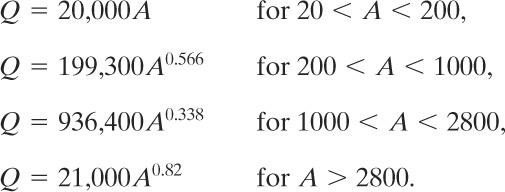
Table 9-2 Environment factors F for Equations 9-37 and 9-38
where
A is the area absorbing heat (in ft2) for the following geometries: for spheres, 55% of total exposed area; for horizontal tanks, 75% of total exposed area; for vertical tanks, 100% of total exposed area for first 30 ft, and
Q is the total heat input to the vessel (in Btu/hr).
The mass flux GT is determined using Equation 9-15 or 9-18.
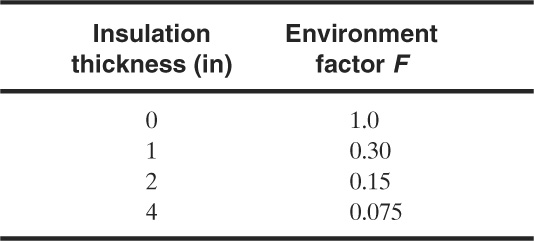
API 52023 suggests a slightly different approach to estimate the heat flux to process equipment as a result of a fire. If prompt fire fighting is available and if the flammable material is drained away from the vessel, then the heat flux is estimated using
23API RP 520, Sizing, Selection, and Installation of Pressure-Relieving Devices in Refineries, 6th ed. (Washington, DC: American Petroleum Institute, 1993).
(9-37)
![]()
If adequate fire fighting and drainage do not exist, then the following equation is used:
(9-38)
![]()
where
Q is the total heat input through the surface of the vessel (Btu/hr),
F is an environment factor (unitless), and
A is the total wetted surface of the vessel (ft2).
The environment factor F is used to account for vessel protection from insulation. A number of values for various insulation thicknesses are shown in Table 9-2.
The surface area A is the area of the vessel wetted by its internal liquid with a height less than 25 ft above the flame source. Wong24 provided considerably more detail on how to determine this and provided a number of equations for various vessel geometries.
24W. Y. Wong, “Fires, Vessels, and the Pressure Relief Valve,” Chemical Engineering (May 2000).
Example 9-9
Leung25 reported on the computation of the required relief area for a spherical propane vessel exposed to fire. The vessel has a volume of 100 m3 and contains 50,700 kg of propane. A set pressure of 4.5 bars absolute is required. This corresponds to a set temperature, based on the saturation pressure, of 271.5 K. At these conditions the following physical property data are reported:
25Leung, “Simplified Vent Sizing Equations.”
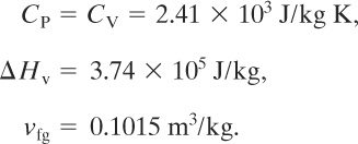
The molecular weight of propane is 44.
Solution
The problem is solved by assuming no overpressure during the relief. The relief vent area calculated is larger than the actual area required for a real relief device with overpressure.
The diameter of the sphere is
The surface area of the sphere is
![]()
The area exposed to heat is given by the geometry factors provided with Equation 9-36:
![]()
The total heat input is found using Equation 9-36:
If we use Equation 9-37 and assume that the vessel is full of liquid, then the entire vessel surface area is exposed to the fire. If we also assume that no insulation is present, then F = 1.0. Then
![]()
which is close to the value estimated using Equation 9-36.
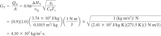
From Equation 9-15 and assuming ψ = 1.0, we obtain
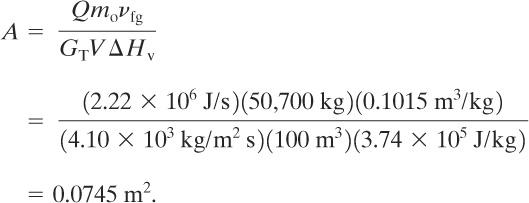
The required vent area is determined from Equation 9-35:
The required diameter is
An alternative way to look at the problem might be to ask the question, What initial fill fraction should be specified in the tank to avoid two-phase flow during a fire exposure incident? No tested correlations are presently available to compute the height of a foam layer above the boiling liquid.
For fire reliefs with single-phase vapor flow the equations provided in sections 9-2 and 9-4 are used to determine the size of the relief.
As mentioned previously, two-phase flow discharges for fire scenarios are possible but not likely. To size the relief for fire and a single-vapor phase, use the heat input determined from Equations 9-36 to 9-38, and determine the vapor mass flow rate through the relief by dividing the heat input by the heat of vaporization of the liquid. This assumes that all the heat input from the fire is used to vaporize the liquid. The relief area is then determined using Equations 9-3 to 9-12.
9-8 Reliefs for Thermal Expansion of Process Fluids
Liquids contained within process vessels and piping will normally expand when heated. The expansion will damage pipes and vessels if the pipe or vessel is filled completely with fluid and the liquid is blocked in.
A typical situation is thermal expansion of water in cooling coils in a reactor, shown in Figure 9-12. If the coils are filled with water and are accidentally blocked in, the water will expand when heated by the reactor contents, leading to damage to the cooling coils.
Figure 9-12 Damage to cooling coils as a result of external heating of blocked-in cooling fluid.
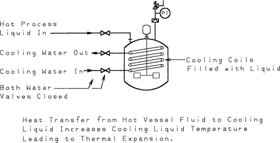
Relief vents are installed in these systems to prevent damage resulting from liquid expansion. Although this may appear to be a minor problem, damage to heat exchange systems can result in (1) contamination of product or intermediate substances, (2) subsequent corrosion problems, (3) substantial plant outages, and (4) large repair expenses. Failure in heat exchange equipment is also difficult to identify, and repairs are time consuming.
A thermal expansion coefficient for liquids, β, is defined as
(9-39)
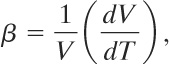
where
V is the volume of the fluid and
T is the temperature.
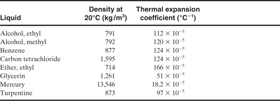
Table 9-3 lists thermal expansion coefficients for a number of substances. Water behaves in an unusual fashion. The thermal expansion coefficient decreases with increasing temperature up to about 4°C, after which the thermal expansion coefficient increases with temperature. Coefficients for water are readily determined from the steam tables.
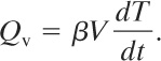
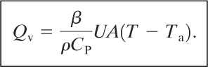
The volumetric expansion rate Qv through the relief resulting from thermal expansion is
(9-40)
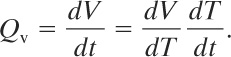
By applying the definition of the thermal expansion coefficient, given by Equation 9-39, we obtain
(9-41)
For a pipe or process vessel heated externally by a hot fluid, an energy balance on the fluid is given by
(9-42)
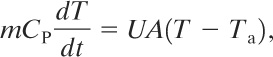
Table 9-3 Thermal Expansion Coefficients for a Variety of Liquids1
1G. Shortley and D. Williams, Elements of Physics, 4th ed. (Englewood Cliffs, NJ: Prentice Hall, 1965), p. 302.
where
T is the temperature of the fluid,
CP is the heat capacity of the liquid,
UA is an overall heat transfer coefficient, and
Ta is the ambient temperature.
It follows that
(9-43)
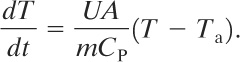
Substituting into Equation 9-41, we obtain
(9-44)

and, invoking the definition of the liquid density p,
(9-45)
Equation 9-45 describes the fluid expansion only at the beginning of heat transfer, when the fluid is initially exposed to the external temperature Ta. The heat transfer will increase the temperature of the liquid, changing the value of T. However, it is apparent that Equation 9-45 provides the maximum thermal expansion rate, sufficient for sizing a relief device.
The volumetric expansion rate Qv is subsequently used in an appropriate equation to determine the relief vent size.
Example 9-10
The cooling coil in a reactor has a surface area of 10,000 ft2. Under the most severe conditions the coils can contain water at 32°F and can be exposed to superheated steam at 400°F. Given a heat transfer coefficient of 50 Btu/hr-ft2-°F, estimate the volumetric expansion rate of the water in the cooling coils in gpm.
Solution
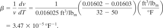
The expansion coefficient b for water at 32°F should be used. This is estimated using liquid volu-metric data from the steam tables over a short range of temperatures around 32°F. However, the steam tables do not provide liquid water specific volume data below 32°F. A value between 32°F and some appropriate higher temperature will suffice. From the steam tables:
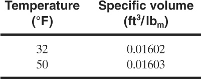
The expansion coefficient is computed using Equation 9-39:
The volumetric expansion rate is given by Equation 9-45:
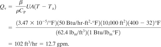
The relief device vent area must be designed to accommodate this volumetric flow.
Suggested Reading
Deflagration Vents
W. Bartknecht, “Pressure Venting of Dust Explosions in Large Vessels,” Plant/Operations Progress (October 1986), 5(4): 196.
Frank T. Bodurtha, Industrial Explosion Prevention and Protection (New York: McGraw-Hill, 1980).
Ian Swift and Mike Epstein, “Performance of Low Pressure Explosion Vents,” Plant/Operations Progress (April 1987), 6(2).
Relief Codes
API RP 520, Recommended Practice for the Sizing, Selection, and Installation of Pressure Relieving Systems in Refineries, 6th ed. (Washington, DC: American Petroleum Institute, 1993).
API RP 521, Guide for Pressure-Relieving and Depressurizing Systems, 3d ed. (Washington, DC: American Petroleum Institute, 1990).
API Standard 2000, Venting Atmospheric and Low-Pressure Storage Tanks (Nonrefrigerated and Refrigerated), 5th ed. (Washington, DC: American Petroleum Institute, 1998).
ASME Boiler and Pressure Vessel Code (New York: American Society of Mechanical Engineers, 1998). NFPA 68, Guide for Venting of Deflagrations (Quincy, MA: National Fire Protection Association, 1998).
Two-Phase Flow
G. W. Boicourt, “Emergency Relief System (ERS) Design: An Integrated Approach Using DIERS Methodology,” Process Safety Progress (April 1995), 14(2).
H. K. Fauske, “Determine Two-Phase Flows During Release,” Chemical Engineering Progress (February 1999).
H. K. Fauske, “Emergency Relief System (ERS) Design,” Chemical Engineering Progress (August 1985).
H. K. Fauske, “Flashing Flows or Some Practical Guidelines for Emergency Releases,” Plant/Operations Progress (July 1985).
H. K. Fauske, “Generalized Vent Sizing Nomogram for Runaway Chemical Reactions,” Plant/Operations Progress (October 1984), 3(4).
H. K. Fauske, “Properly Sized Vents for Nonreactive and Reactive Chemicals,” Chemical Engineering Progress (February 2000).
H. K. Fauske and J. C. Leung, “New Experimental Technique for Characterizing Runaway Chemical Reactions,” Chemical Engineering Progress (August 1985).
K. E. First and J. E. Huff, “Design Charts for Two-Phase Flashing Flow in Emergency Pressure Relief Systems.” Paper presented at 1988 AICHE Spring National Meeting.
Harold G. Fisher, “DIERS Research Program on Emergency Relief Systems,” Chemical Engineering Progress (August 1985), p. 33.
H. G. Fisher, H. S. Forrest, S. S. Grossel, J. E. Huff, A. R. Muller, J. A. Noronha, D. A. Shaw, and R. J. Tilley, Emergency Relief System Design Using DIERS Technology (New York: American Institute of Chemical Engineers, 1992).
J. C. Leung, “A Generalized Correlation for One-Component Homogeneous Equilibrium Flashing Choked Flow,” AICHE Journal (October 1986), 32(10): 1743.
J. C. Leung, “Simplified Vent Sizing Equations for Emergency Relief Requirements in Reactors and Storage Vessels,” AICHE Journal (October 1986), 32(10): 1622.
J. C. Leung and H. G. Fisher, “Two-Phase Flow Venting from Reactor Vessels,” Journal of Loss Prevention (April 1989), 2(2): 78.
J. C. Leung and M. A. Grolmes, “The Discharge of Two-Phase Flashing Flows in a Horizontal Duct,” AICHE Journal (March 1987), 33(3): 524.
J. C. Leung and M. A. Grolmes, “A Generalized Correlation for Flashing Choked Flow of Initially Sub-cooled Liquid,” AICHE Journal (April 1988), 34(4): 688.
Problems
9-1. Estimate the diameter of spring-type liquid reliefs for the following conditions:
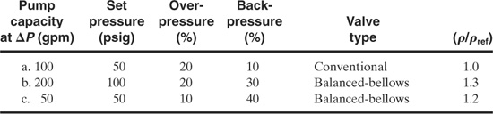
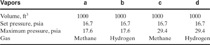
9-2. Determine the diameter of a spring-type vapor relief for the following conditions. Assume for each case that g = 1.3, the set pressure is 100 psia, and the temperature is 100°F.
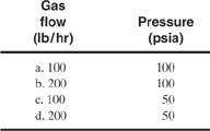
9-3. Determine the required diameter for rupture discs for the following conditions. Assume a specific gravity of 1.2 for all cases.

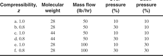
9-4. Determine the required diameter for rupture discs in vapor service for the following conditions. Assume that nitrogen is the vent gas and that the temperature is 100°F.
9-5. Determine the proper relief diameter for the following two-phase flow conditions. Assume in all cases that L/D = 0.0.

9-6. How is the overpressure included in the design of two-phase reliefs?
9-7. Determine the relief vent areas for the following two-phase fire scenarios. Assume a spherical vessel in each case.
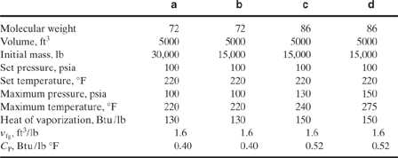
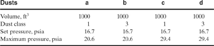
9-8. Determine the relief size for spray dryers operating under the following conditions:
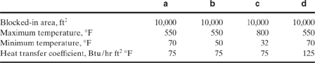
9-9. Determine the size of relief required to protect the following cooling coils against thermal expansion. Water is used for each case. Assume that the tubes can withstand a pressure of 1000 psig and that the normal operating pressure is 200 psig. Assume a set pressure of 500 psig, an overpressure of 20%, and no backpressure.
9-10. Consider Problem 9-9, part a. This time use alcohol as a liquid medium with a thermal expansion coefficient of 1.12 10–3/°C. The heat capacity of the alcohol is 0.58 kcal/kg °C, and its density is 791 kg/m3. Determine the relief size required.
9-11. A process vessel is equipped with a 2-in rupture disc set at 100 psig and designed for 10% overpressure. A nitrogen line must be added to the vessel to provide the capability of purging and/or pressure discharging liquids. What size line would you select if the nitrogen is available from a 500-psig source? The temperature is 80°F.
9-12. Home hot water heaters contain relief devices to provide protection in the event that the heater controls fail and the water is heated to a high temperature.
A typical water heater contains 40 gal of water and has a heat input of 42,000 Btu/hr. If the heater is equipped with a 150-psia spring relief device, compute the area required for relief. Hint: Two-phase flow is expected. Assume no overpressure.
Also compute the relief vent size assuming all vapor relief. Assume 20% back-pressure.
9-13. A cylindrical tank, 4 ft in diameter and 10 ft long, is completely filled with water and blocked in. Estimate the thermal expansion rate of the water if the water is at 50°F and the steel shell of the tank is suddenly heated to 100°F by the sun. Assume a heat transfer coefficient of 50 Btu/hr ft2 °F and that only the top half of the tank is heated.
If the tank is exposed to fire, what is the required relief area? Assume no overpressure. The tank MAWP is 200 psig.
9-14. A 10-ft wide by 10-ft long by 10-ft high shed is used to store tanks of methane. What deflagration vent area is required? Assume a maximum internal overpressure of 0.1 psig.
9-15. A spray dryer is used to dry vitamins in powder form. The dryer consists of a cylindrical section 12.0 ft high and 5 ft in diameter. Attached to the bottom of the cylindrical section is a cone section for collecting the dried powder. The cone is 5 ft long. If the deflagration index for the vitamin powder is 80 bar m/s, determine the area required for a deflagration vent. Assume that the vent opens at 0.2 bar gauge and that the maximum pressure is 0.5 bar gauge.
9-16. A beverage dispensing system consists of a bottle of beverage, a dispensing hose with valve, and a CO2 system to keep the beverage pressurized. The CO2 system includes a small bottle of high-pressure liquefied CO2, and a regulator to regulate the gas pressure delivery to the beverage.
A typical beverage system contains a 7.75-gal beverage bottle, a 5-lb bottle of liquefied CO2, and a regulator set at 9 psig. The regulator is connected directly to the CO2 bottle, and a 0.5-in (internal diameter) plastic hose connects the regulator to the beverage bottle. The liquefied CO2 saturation vapor pressure is 800 psia. Assume a temperature of 80°F.
A pressure relief system must be designed to protect the beverage bottle from over-pressure. The relief device will be installed in the CO2 line where it enters the beverage container.
a. Determine the most likely scenario contributing to overpressure of the beverage container.
b. Must two-phase flow be considered?
c. Determine the vent area required, assuming a set pressure of 20 psig and an over-pressure of 10%. Also assume a spring-type relief.
9-17. You have been assigned the task of reviewing the relief scenarios for a specific chemical reactor in your plant. You are currently reviewing the scenario involving the failure of a nitrogen regulator that provides inert padding to the vapor space of the reactor. Your calculations show that the maximum discharge rate of nitrogen through the existing relief system of the vessel is 0.5 kg/s. However, your calculations also show that the flow of nitrogen through the 1-in supply pipe will be much greater than this. Thus under the current configuration a failure of the nitrogen regulator will result in an overpressuring of the reactor.
One way to solve the problem is to install an orifice plate in the nitrogen line, thus limiting the flow to the maximum of 0.5 kg/s. Determine the orifice diameter (in cm) required to achieve this flow. Assume a nitrogen source supply pressure of 15 bar absolute. The ambient temperature is 25°C and the ambient pressure is 1 atm.
9-18. The reactor system in a pilot plant contains stock tanks that are 24 in in diameter and 36 in high. A relief system must be designed to protect the vessel in the event of fire exposure. The vessel contains a flammable polymer material. What rupture disc diameter is required to relieve the vessel properly? Assume a discharge pressure of 10 psig. The molecular weight of the liquid is 162.2, its boiling point is 673°R, the heat of vaporization is 92.4 Btu/lb, and the heat capacity ratio of the vapor is 1.30.
9-19. A horizontal vessel, 10 ft long and 3 ft in diameter, contains water. What relief size is required to protect the vessel from fire exposure? Assume the following: vapor relief only, MAWP of 200 psig, conventional spring-operated relief.
9-20. A batch chemical reactor contains 10,000 kg of reacting liquid material. A relief device must be properly sized for a potential runaway reaction.
A laboratory test has shown that the reaction will not result in a two-phase relief. Thus a vapor relief system must be designed. Furthermore, calorimeter tests indicate that the maximum self-heat rate is 40°C/min. The physical properties of the material are also reported:
Heat capacity of liquid: 2.5 kJ/kg K
Heat of vaporization: 300 kJ/kg
Molecular weight: 100
Vapor acts as an ideal triatomic gas.
a. Determine the maximum vaporization rate during a runaway reaction (in kg/s).
b. Determine the relief diameter (in m) required to vent the runaway reaction. Assume a MAWP of 7 bar gauge, 10% backpressure, and a conventional spring-operated relief. Assume a temperature of 200°C at the relief conditions.
9-21. A 1-in (internal diameter) pipe is used to supply water to a low-pressure tank with an MAWP of 20 psig. The water is supplied through a regulator from a source with a maximum pressure of 100 psig. Determine the diameter of a conventional spring-operated relief required to protect the vessel from a regulator failure. Be sure to state clearly any assumptions and your justifications for them.
9-22. A 500-gpm pump is used to provide water to a reactor vessel. If the pump continues to operate, the reactor might be overfilled and overpressurized. Determine the relief diameter (in inches) required to protect the vessel. The MAWP of the vessel is 100 psig. Please state clearly any additional assumptions required for your calculation. Assume a 10% backpressure and a 10% overpressure in the relief system.
9-23. a. Calculate the mass flux (kg/m2s) of gaseous material through a leak assuming that the material is stored at its vapor pressure within the vessel (9.5 × 10⁵ Pa abs). Assume that the material is stored at 25°C, that it is discharged to 1 atm pressure, and that its molecular weight is 44.
b. Calculate the mass flux (kg/m2s) of two-phase material through the same leak under the same conditions of part a. Assume that the discharge length is greater than 10 cm. Additional physical property data are:
Heat of vaporization: 3.33 × 10⁵ J/kg
vfg: 0.048 m3/kg
Heat capacity of liquid: 2.23 × 10³ J/kg K
Heat capacity of vapor: 1.70 × 10³ J/kg K
c. Comment on the difference in flux rates between parts a and b. In general, relief systems designed for two-phase flow must be larger than those for all-vapor flow. Is this consistent with the results of parts a and b? Why?
d. Calculate the energy discharge rate for the discharge of part a. Assume that the energy content of the vapor is due to the heat of vaporization of the liquid to gas.
e. Calculate the energy discharge rate for the discharge of part b. Assume that the energy is due to the sensible heat increase of the two-phase discharge stream and that the temperature of the discharge is 10 K higher.
f. Compare the results of parts d and e. How many times larger must the area of the two-phase discharge be in order to remove energy at the same rate as the single-phase relief? Comment on the implications for relief systems on reactor vessels.
9-24. The RSST (reactive system screening tool) is a laboratory device used to characterize the reactive nature of liquid materials. It is essentially an adiabatic calorimeter, with the test sample heated at a constant temperature rate until an exothermic reaction is encountered.
Assume that a sample is being heated in the RSST. During an exothermic reaction, the energy of reaction heats the sample and increases its temperature. If the reaction is first order in concentration, then, if the heat of reaction is approximately constant, the increase in temperature will also be first order.
a. Show that for a first-order system, a plot of
![]()
versus –1000/T will produce a straight line of slope (E/1000 Rg) and an intercept of ln A, where
T is the absolute temperature (K),
Tmax is the maximum temperature (K),
t is the time (s),
E is the activation energy (energy/mol),
Rg is the ideal gas constant (energy/mol deg), and
A is the pre-exponential factor (time–1).
It is also assumed that the reaction rate follows a typical Arrhenius function as follows:
![]()
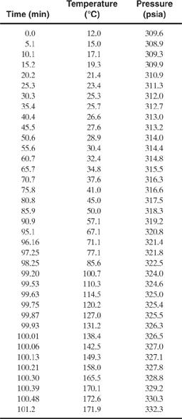
b. The following table provides a set of data collected from an RSST run. Is the reaction first order? If so, determine the activation energy and the pre-exponential factor for the reaction.
9-25. A relief device must be designed for a vessel to relieve 1800 gpm of crude oil liquid in the event that a discharge line is blocked. The MAWP is 250 psig, and a maximum back-pressure of 50 psig is expected. The specific gravity of the oil is 0.928, and its viscosity is 0.004 kg/m s.
a. Specify an appropriate set pressure and overpressure for this relief.
b. What type of relief should be used: a rupture disc, a conventional spring-operated relief, or a balanced-bellows relief?
c. Determine the relief diameter required, in inches.
9-26. A pole barn with thin metal walls must be fitted with a vent to safely vent a hydrocarbon deflagration from the combustion of a hydrocarbon similar to propane. The maximum pressure that this building can withstand is estimated at 0.5 psi. Determine the vent area required for this structure if the total internal surface area of the structure (including floor and roof) is 24,672 ft2.
9-27. A vent must be designed for a room that is 20 ft long, 30 ft wide, and 20 ft high. The room is used for dispensing flammable liquids. The fundamental burning velocities of the liquid vapors are less than 1.3 times that of propane. One wall of the room is located against the wall of another structure and is thus not available for a vent.
a. Determine the vent area required if the maximum pressure that the room can withstand is 0.69 psi. How does this area compare to the wall area available for the vent?
b. Determine the vent area required if the maximum pressure that the room can withstand is 1.04 psi. Is adequate wall area now available for the vent?
9-28. A relief device must be installed on a vessel to protect against an operational upset. The relief must discharge 53,500 lb/hr of hydrocarbon vapor. The relief temperature is 167°F, and the set pressure is 75 psig. Assume an overpressure of 10% and a backpressure of 0 psig. The hydrocarbon vapor has a molecular weight of 65, a compressibility of 0.84, and a heat capacity ratio of 1.09. Determine the diameter of the relief.
9-29. A process vessel is equipped with a 2-in rupture disc set at 100 psig and designed for 10% overpressure. A nitrogen line must be added to the vessel to provide the capability of purging and/or pressure discharging liquids. What size nitrogen line would you select if the nitrogen is available from a 500-psig source? The ambient temperature is 80°F.
9-30. A spray dryer is used to dry a dust with a KSt value of 230 bar m/s. The dryer is a vertical cylinder 2 m in diameter and 3 m high.
a. Estimate the vent area required if the dryer is a low-pressure structure capable of withstanding 0.05 bar gauge.
b. Estimate the vent area required if the dryer is capable of withstanding a pressure of 0.2 bar gauge. Assume a vent release pressure of 0.15 bar gauge.