1 Short Projects
Typical complex projects can take several days to complete. To give you as much practical knowledge as possible and not focus on certain themes, I would like to show you some typical projects in this chapter. Along the way you will become familiar with other modeling tools and techniques not mentioned before.
The projects were chosen to demonstrate a complete production cycle from modeling to texturing and lighting, right up to the final rendering. The first example shows the use of primitives for modeling a flashlight. The second workshop demonstrates the use of the HYPERNURBS object and the realistic creation of a carabiner. The third example goes more in an artistic direction and shows the construction of an antique glass vase. Have fun and good luck!
Modeling with Parametric Objects—A Flashlight
Many technical shapes and objects for daily use can be built from simple shapes. Shapes such as a cylinder, sphere, or cube are offered by CINEMA 4D in a ready-to-use format as so-called primitives and can be easily modified in the viewports by value fields or virtual handlers. These objects also have the advantage that they can be rounded or further subdivided, for example, when a still image needs more DETAILS or when a curve has to have more definition.
We will start this workshop with an empty scene. Delete all objects in your scene or open a new scene at FILE>New. Several scenes can be opened in CINEMA 4D. You can switch between these scenes in the wiNdow menu of CINEMA 4D.
The Head of the Flashlight
First add a Cone object and change the upper radius to 90, the lower radius to 125, and the HEIGHT to 320 units, as shown in Figure 1.1. I took these measurements from a real flashlight. The units of these values generally don’t matter to CINEMA 4D. The object will have the same size regardless of whether you use millimeter, centimeter, or kilometer as units. The numerical value is what is important. For example, if you measure 32 mm on a real object, then this measurement can become 320 units in CINEMA 4D. The purpose for this is to have enough decimal places so adjustments can be made later if necessary. I used the same principle in this example. All measurements were done in millimeters and then multiplied by 10.
I increased the number of SEGMENTS around the cone circumference to 72 so there will be more detail in a close-up later on. You can work with a lower number of SEGMENTS if you want to use multiple flashlights in your scene and need to watch the number of polygons. There will be a deformation in the next step; therefore, additional points are needed on the surface of the cone. In that case the subdivision along the HEIGHT is set to 8.
The cone also has small roundings at its caps. Hardly any real object has perfectly sharp edges. This should be kept in mind during modeling. The highlights alone that will be captured by the rounded edge can improve the quality of an image tremendously.
The head of the flashlight is supposed to be bent in a soft curve between the different radii of the caps. This can be accomplished
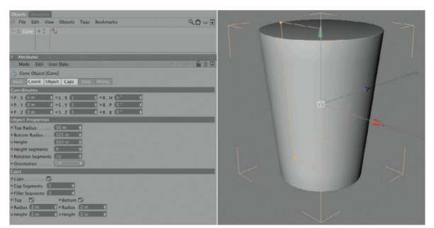
— Figure 1.1: A cone object will create the head of the flashlight.
quickly with a BULGE deformer. Subordinate the deformer under the cone, as shown in Figure 1.2. Make sure that the Y axis of the deformer points vertically up or down because the constriction or bulging of this deformer is always calculated vertically to the Y axis. This should automatically be the case if you haven’t changed the position or direction of the cone.
Now increase the value for STRENGTH of the BULGE object in the ATTRIBUTE MANAGER. You should be able to see now how the surface of the cone bulges outward in the middle. Increase the Y part of the deformer size to 320 units and the strength to about 12% in order to get a result like that shown in Figure 1.2. If the bulge of the cone appears too angled, then increase the number of SEGMENTS along the HEIGHT of the cone in its dialog box, as shown in Figure 1.1.
THE FOCUS RING
Above the head of the flashlight is the separately rotating focus ring, which turns the flashlight on or off and regulates the focus of the light beam for different distances. As the name indicates, it is a simple ring that is available as a primitive. I would like to use a spline with a NURBS object, though. Add a RECTANGLE spline and place it in the front viewport (XY viewport), above the right edge of the upper cone cap, as shown in Figure 1.3.
I gave the rectangle a WIDTH of 30 and a HEIGHT of 100 units. Zoom in to make sure the lower edge of the spline is level with the cone. You can see also the numerical value of the position in Figure 1.3.
Instead of using the built-in rouNdiNg option of the RECTANGLE spline, we convert the spline with MAKE EDITABLE in the FUNCTIONS menu or by using the (C) key. The parameters of the spline in the ATTRIBUTE MANAGER are lost but we can now edit the points of the spline directly in USE POINT TOOL mode.
Use the LIVE or FRAME SELECTION to select either the upper or lower two points of the rectangle. Then right click into an empty area in the viewport and use CHAMFER from the
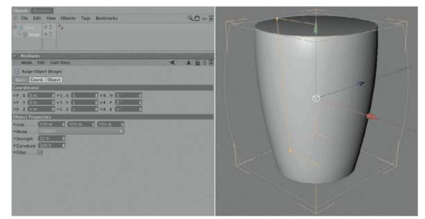
— Figure 1.2: Bending the cone.
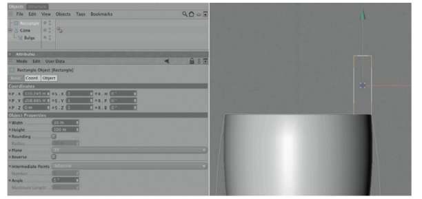
— Figure 1.3: A rectangle spline is used as the profile for the focus ring.
context menu. This command can also be found in the STRUCTURE menu under the EDIT SPLINE entry. While holding the mouse button, drag the mouse to the left or right to round the spline points, or enter a value in the ATTRIBUTE MANAGER after selecting the tool.
In this case, that should be enough to create an optically pleasing result. When you are done with the two points, select the other two points and do the same, but with a different radius. Try to match the radius in Figure 1.4.
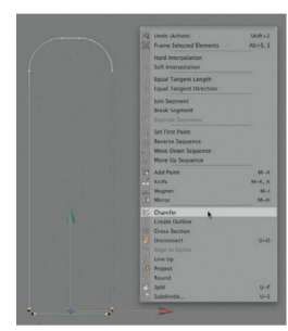
— Figure 1.4: Individual rounding of the spline corner.
The Lathe NURBS Object
This completes the desired profile of the focus ring. To develop a three-dimensional shape, we will use a LATHE NURBS object and subordinate the rounded rectangle spline under it. Instantly an object is generated, as can be seen in Figure 1.5.
The Lathe NURBS rotates the subordinated spline around its Y axis. If your result looks different, check the location of the Lathe NURBS object and then control the position of the spline. The rectangle spline should be visible in the XY viewport and positioned directly above the upper edge of the cone.
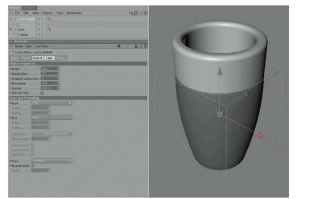
— Figure 1.5: The focus ring gets volume by using the Lathe NURBS.
Increase the number of SUBDIVISION in the Lathe NURBS object to the same value as was used for the circumference elements of the cone. In my case it was 72 SUBDIVISION. Otherwise there are no settings to be made.
The Handle of the Flashlight
This completes the outer shape of the flashlight head, and we now can concentrate on the handle. It can be made out of a cylinder object, the HEIGHT of which should be 940 and the RADIUS 85 units. Here I use 72 SEGMENTS again around the circumference and a small rounding at the caps. Be sure that the cylinder is aligned along the Y ORIENTATION. Use the ORIENTATION menu within the cylinder settings in the ATTRIBUTE MANAGER or rotate the cylinder manually by 90° so it is positioned vertically under the model of the upper part of the flashlight.
Move the cylinder down along the Y axis until the upper cap is level with the head piece of the flashlight. Figure 1.6 shows the desired result.
The Bottom Cap of the Flashlight
The screw-on bottom of the flashlight is more difficult because there is an additional hole that can be used for a wrist strap. First we will take care of the outer shape of the bottom cap and again use a rectangle spline, as shown in Figure 1.7. Change its size to a HEIGHT of 90 and a radius of 170 units, and
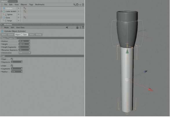
— Figure 1.6: A simple cylinder as the shaft of the flashlight.
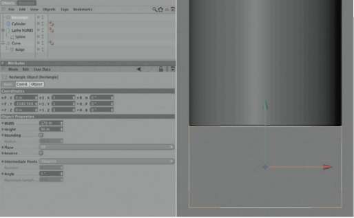
— Figure 1.7: Another rectangle spline as the base for the bottom cap of the flashlight.
place it as level as possible under the cylinder of the handle.
In order to gain direct access to the rectangle, you need to convert the spline with the (C) key as well as select the two points on the left side of the rectangle in the USE POINT TOOL mode. Switch the mode in the MANAGER to WORLD and set the X position value to 0. This should move the two selected points to the WORLD Y axis.
Now select the lower of the recently moved points and right click in an empty spot in the viewport. In the context menu choose SET FIRST POINT. Then deactivate the CLOSE SPLINE option of the former rectangle spline in the ATTRIBUTE MANAGER, as shown in Figure 1.8. In case you can’t see this option, click on the converted spline again in the OBJECT MANAGER to select it.
The reason for this action is that the spline can now be used with the Lathe NURBS to create a massive cap. Because the two points are positioned on the WORLD Y axis, a closed cap is automatically created when the spline is rotated. Of course we could have used a cylinder for this part, but with the spline it is easier to create round corners, especially when different radii are used. We already did that with the focus ring of the flashlight.
As mentioned, we will now create a new LATHE NURBS object and place the open spline as its child, as shown in Figure 1.9. If the location of the spline wasn’t changed, then a cylindrical object should appear immediately. Then select the left points of the spline one by one and use the CHAMFER function to round the corners with different radii, as shown in Figure 1.9. This function can be found in the context menu after a right click into the empty viewport. If you have problems seeing the points on the spline, then deactivate the Lathe NURBS for a moment by clicking on the green checkmark behind the name in the OBJECT MANAGER. Another click on the checkmark activates the Lathe NURBS again. The ENABLED option in the BASIC settings of the Lathe NURBS in the ATTRIBUTE MANAGER has the same purpose.
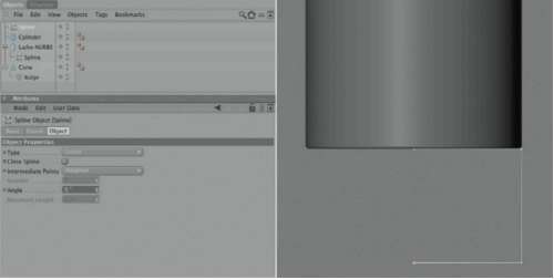
— Figure 1.8: The opened rectangle spline.
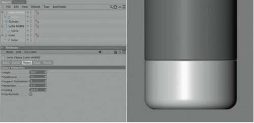
— Figure 1.9: The Lathe NURBS rotates the spline and creates a closed volume.
USING SYMMETRY
Two parts should now be subtracted from the bottom cap to make space for a pass-through wrist strap. So first we need to create a new cylinder and give it a RADIUS of about 84 units. The HEIGHT is not so important for the next few steps. It should just be large enough so the cylinder protrudes past the lateral boundary of the bottom cap.
The cylinder should be located parallel to the WORLD X axis. Therefore, pay attention to the +X or -X setting in the ORIENTATION menu of the cylinder. The sign doesn’t matter for our purposes. Place the cylinder in the XY viewport so that it doesn’t quite reach the Y axis. This can be seen in Figure 1.10 in the upper right image. Take a look at only the left of the two cylinders in this image. The right cylinder will automatically be generated in the next step by mirroring.
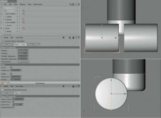
— Figure 1.10: The volume of two cylinders is supposed to be subtracted from the bottom cap.
In the ZY viewport, which is the side view of the scene, the cylinder should be located slightly in front of the bottom cap of the flashlight and close to the middle axis. The image on the bottom left of Figure 1.10 shows that placement.
In order to create a symmetrical cylinder on the other side, it is possible to just make a copy of the cylinder. It would have to be placed manually, though, and adjusted every time the first cylinder is changed. It is easier to use the SYMMETRY object, which can be found in OBJECTS>MODELING or in the corresponding icon menu. Place the cylinder as a child of the SYMMETRY object. Depending on the chosen symmetry plane, a virtual copy of the cylinder appears in the scene. The axis system of the SYMMETRY object acts as the base for the mirroring. The mirror plane there fore has to be set to ZY in the ATTRIBUTE MANAGER so the mirrored cylinder appears to the right of the original. Correct the position of the cylinder if necessary to get the result shown in Figure 1.10. Also add a fillet to the caps in the ATTRIBUTE MANAGER so a rounding is created when the cylinder is subtracted from the bottom cap of the flashlight. A radius of 5 units should be enough. Since we work entirely parametric, this setting can be changed anytime.
CONNECTING OBJECTS WITH THE BOOLE OBJECT
Many complex forms can be created by combining simple shapes. The BOOLE object can be helpful, especially with mechanical parts.
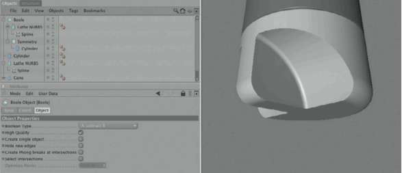
— Figure 1.11: The BOOLE object enables the subtraction of objects from each other.
It can be used to subtract shapes from an object or to calculate intersections between objects. In our example we created the cylinders for this purpose, which are currently stuck inside the bottom cap of the flashlight.
Therefore, we add a BOOLE object, found in the corresponding icon menu or in OBJECTS>MODELING. It can be set to different modes in the ATTRIBUTE MANAGER in the BOOLEAN TYPE menu. A SUBTRACT B means that the second object subordinated under the BOOLE object (B) is subtracted from the first subordinated object (A).
The other options of the BOOLE object influence the quality of the calculation and are only of interest for further manipulation of the calculated object. The interconnected objects can still be edited as separate entities. With CREATE SINGLE OBJECT these objects can be merged to one single surface. HIGH QUALITY simply activates a different algorithm. Sometimes, though, the deactivation of this option can lead to a better result. HIDE NEW EDGES merges the faces created by the union of the objects into N-gons. This can result in a cleaner look and a more efficient geometry, and should be used when the BOOLE object is to be converted into an editable polygon object.
Currently, all this is not that important to us. Just make sure that the BOOLEAN type A SUBTRACT B is selected. Then subordinate the Lathe NURBS object and the SYMMETRY object under the BOOLE object. The order of the objects is important because the cylinders in the SYMMETRY object will be subtracted from the capsular Lathe NURBS object. Figure 1.11 shows that and the expected result. The cylinders reduce the front part of the bottom cap of the flashlight to a thin bridge in the center. If we drill a hole in this bridge, we can later pull a wrist strap through it.
In this step the position and diameter of the bore are defined by another cylinder. The length of the cylinder is also not important here, as long as it penetrates the bridge of the bottom cap all the way through. A radius of 15 units and a position as shown in Figure 1.12 should be enough.
In order to be able to subtract the cylinder from the Lathe NURBS cap for the bore, as well as the two laterally placed cylinders, we have to combine the SYMMETRY object and the new cylinder in a second BOOLE object. Set the second BOOLE object to A UNION B

— Figure 1.12: A slim cylinder defines the bore.

— Figure 1.13: BOOLE objects can be combined to create more complex shapes.
mode to get a solid unit, one volume created from the three cylinders. This unit can then be subtracted from the Lathe NURBS as we did before. Figure 1.13 shows the structure of the hierarchy between the BOOLE objects on the left and the result on the right. Since all objects remain parametric, the WIDTH of the bridge can be changed anytime by moving the cylinder in the SYMMETRY object. The bore can also be adjusted by changing the radius of the slim cylinder.
The Knurling at the Head of the Flashlight
When adding roughness to surfaces, we have to first ask whether these need to be mod-eled or whether it is enough to use a material property. In the case of the knurling on the head piece of the flashlight, I decided to model it with a ready-to-use STAR spline. I’ve set the number of points to 160 teeth and oriented the STAR spline along the XZ plane.
An inner radius of 126 and an outer radius of 127 generate flat spikes that are well suited for our purpose. Place the STAR spline as a child of a new EXTRUDE NURBS object from the OBJECTS>NURBS menu. A movement of 50 units along the Y direction should be enough.
Now move the star under the focus ring so that the knurling is positioned as shown in Figure 1.14. The figure also shows the other settings of the Extrude NURBS and the STAR spline.
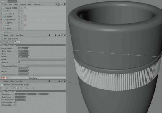
— Figure 1.14: Adding the knurl as its own object.
CREATING A HOLE SPLINE
Everything looks fine from the outside, but there are some DETAILS missing from the inside of the flashlight head. In order to add these we need to drill out the recently created corrugation. We are forced, because of the shape of the knurl, to create caps through the Extrude NURBS. This, though, causes a problem inside the flashlight because the caps of the star will penetrate the reflector of the bulb, which we will model later. Consequently, the corrugation would have to be restricted to the outside casing of the flashlight.
A BOOLE object can be used to subtract a cylinder from the Extrude NURBS of the star. I would like to take this opportunity, though, to show the creation of a hole spline, which means curves with encased hollows.
Add a CIRCLE spline and subordinate it under the STAR spline in the OBJECT MANAGER. The advantage here is that we can adjust the alignment and position of the circle in the COORDINATE MANAGER. Therefore, set the COORDINATE MANAGER to OBJECT mode and reset all position and rotation values to 0. Don’t forget to press the APPLY button. Then check the plane of the CIRCLE spline and, if necessary, correct it in the ATTRIBUTE MANAGER to the setting XZ. Now the star and circle are located in exactly the same plane and position.
Connect Splines
To create a hole spline, the two splines have to be combined into a single one. Because both are still parametric they need to be converted first. Select the two splines with (Ctrl) or clicks, or by a frame selection with the
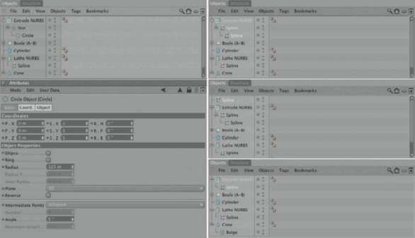
— Figure 1.15: Apply a notch to the Extrude NURBS.
mouse in the OBJECT MANAGER. Then select MAKE EDITABLE in the FUNCTIONS menu or simply use the (C) key. The result can be seen in the upper right of Figure 1.15. The two still selected splines can now be combined into a new spline with FUNCTIONS> CONNECT. This new spline now appears on the top of the list in the OBJECT MANAGER. The two original splines still remain. The center image on the right side of Figure 1.15 shows this situation.
You can now DELETE the two original splines. Just use the (Delete) key or select the DELETE command under edit in the OBJECT MANAGER. Of course, the two splines about to be DELETEd have to be selected first.
The newly connected spline can now be placed as a child of the Extrude NURBS, as shown on the bottom right of Figure 1.15.
Before the connection we dealt with two individual splines that used different interpolations. The star had a linear interpolation and the circle a cubic interpolation. After connecting the two splines, only one type of interpolation can be used for both SEGMENTS. In the case of the linear interpolation, it would look like the left side of Figure 1.16. The star remains unchanged, while the circle on the inside, since its points are no longer connected in a cubic manner but in a linear one, changes to a square.
In this case you can switch to BEZIER interpolation. Select the inner four points belonging to the circle and right click into the empty area of the viewport. Select SOFT INTERPOLATION in the context menu. The selected points automatically receive soft interpolated tangents. Now the circle gets its shape back almost completely, as seen in the right part of Figure 1.16.
In order to get back the outer corners of the star spline, invert the current point selection of the four inner points by selecting SELECTION>INVERT and right clicking in the viewport. Choose HARD INTERPOLATION in the context menu to reduce the tangents of the points to 0 lengths.
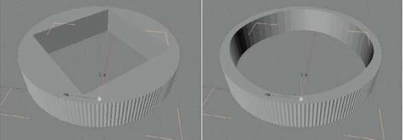
— Figure 1.16: Influencing the shape of the hole.
The Refector of the Flashlight
When looking through the focus ring, we see the cap of the deformed cone. This will now be changed by adding some more parts. Start with a new CIRCLE spline, which can be deformed individually along its two axes by using the ELLIPSE option in the ATTRIBUTE MANAGER. As you can see in Figure 1.17, I aligned the ellipse in the front view so it remains exactly on the WORLD Y axis. Its lower end protrudes into the head part of the flashlight in such a way that the curve of the ellipse portrays the reflector.
I used a radius of 105 units in the X direction and 100 units in the Y direction. This is not set in stone, though. The ellipse shouldn’t extend to the upper part of the focus ring. Instead it should extend into the lower part.
Similar to the bottom part of the flashlight, the reflector will be built by rotating the ellipse spline using a Lathe NURBS. But we only need the bottom part of the ellipse. Therefore, convert the CIRCLE spline by pressing the (C) key, switch into the USE POINT TOOL mode, and select the lowest point, as shown in Figure 1.18. With a right click into an empty part of the viewport, open the context menu and select SET FIRST POINT. This is necessary because the spline has to be opened, and this opening is always located between the first and last point of the spline. Deselect the CLOSE SPLINE option of the spline in the ATTRIBUTE MANAGER and DELETE the two ellipse points on top and on the left. What remains is the lower right quarter part of the ellipse, as shown on the right side of Figure 1.18.
Now we will shape the part of the spline that protrudes from the flashlight WITHOUT changing the remaining shape of the spline. Therefore, we need to add a point to the spline. Activate the MOVE tool in USE POINT TOOL mode and hold the (Ctrl) key while clicking on the spline. This creates a new point at the spot where we clicked WITHOUT changing the course of the spline.
Click the mouse in the area of the spline just before where it reaches the inner wall of the focus ring. The left part of Figure 1.19 shows the location and the newly created point. Then select the point at the upper end of the spline and select HARD INTERPOLATION in the context menu. Now move this point down as far as is shown on the right side of Figure 1.19. You will have to adjust the upper tangent of the new spline point, so hold the (Shift) key in order to move the tangent arms independent of each other. The goal is to soften the transition between reflector and focus ring.
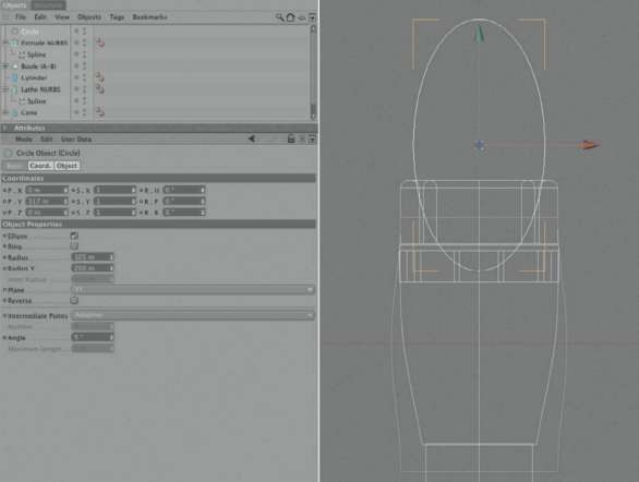
— Figure 1.17: The basic shape of the reflector in the head of the flashlight is created with the help of the Circle spline.
Add a LATHE NURBS object and subordinate the spline under it. For a better view of the reflector it might be helpful to make the surrounding objects invisible. Use the upper of the two gray dots behind the objects in the OBJECT MANAGER. Double clicking on the dot changes its color to red and makes the object invisible. Another click on the dot allows the object to appear again.
THE LIGHT BULB IN THE REFLECTOR
In order to get our flashlight to illuminate, we need a light bulb at the base of the reflector. We could just put an object at the reflector, but instead I want to cut a hole into the reflector so the light bulb can protrude through it. Generally it would be enough to move the lowest point of the reflector spline away from the Y axis, creating an opening at the Lathe NURBS. The flank of the reflector would change its tilt at the same time, though, and I want to avoid this.
As a result we will use a new slim CYLINDER and combine it with a BOOLE object, as shown in Figure 1.20. The volume of the vertical cylinder is then subtracted from the reflector bowl and creates the desired opening. Note that the BOOLE object does not use the A SUBTRACT B mode this time since we aren’t working with two volumes. The
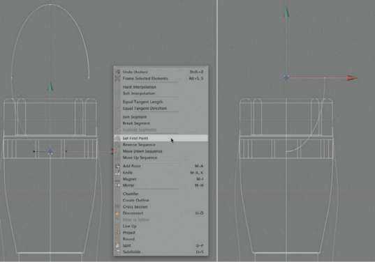
— Figure 1.18: Removing part of the ellipse.
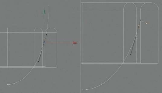
— Figure 1.19: Shaping the upper edge of the spline.
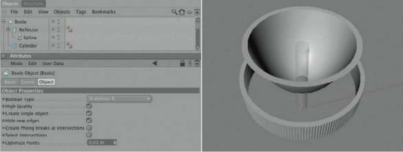
— Figure 1.20: Cutting out the opening for the light bulb.
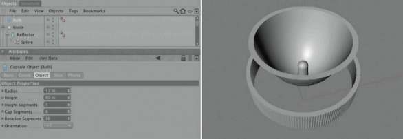
— Figure 1.21: Adding a capsule as the light bulb.
reflector is just a thin-walled bowl. To create the opening we have to use the A WITHOUT B mode. The volume of the cylinder will then be subtracted from the open bowl and creates the desired effect. Figure 1.20 shows, superimposed on the right, the cylinder and underneath the reflector with the resulting opening.
For the actual light bulb we don’t need many DETAILS. I recommend using the CAPSULE object of CINEMA 4D. Its shape is close enough to the shape of a light bulb. Choose a capsule RADIUS slightly under the radius of the cylinder used to cut the hole in the reflector. Figure 1.21 shows my settings and the finished result on the right.
THE COVER GLASS OF THE FLASHLIGHT
The only thing missing is the cover glass on top of the reflector. It is very thin and doesn’t have any special facets. As a result we can use a simple flat cylinder for this part. Add a new cylinder, align it vertically, and match its radius to the upper edge of the reflector. One unit is enough for the HEIGHT. Make sure that the cylinder lies
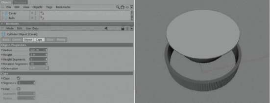
— Figure 1.22: A flat cylinder acts as the cover glass.
flush on top of the reflector, as shown in Figure 1.22.
FINISHING THE MODEL
After making all parts of the flashlight visible again, depending on the intrusion depth of the reflector, we notice something. Even though we have faded out the knurling by building the hole spline for the reflector, the upper cap of the deformed cone is still in the way. We could convert the cone into a POLYGON object and DELETE the cap, but then we would lose the parametric properties of the cone. Therefore, I decided to use a BOOLE object to subtract a cylinder from the upper part of the cone.
Figure 1.23 shows the necessary hierarchical structure and the position of the cylinder on the left side. As for the size of the cylinder, it is important only that it doesn’t penetrate the sides of the cone and that it leaves enough space for the lower end of the reflector and the light bulb. This completes the model and we can now focus our attention on the surface and the lighting.
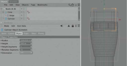
— Figure 1.23: Making space for the reflector.
The Texturing of the Flashlight
Part of the flashlight handle has a diamond-shaped pattern, which makes it less slippery. I don’t want to use additional geometry, like with the knurling beneath the focal ring. This time I will use bump, a material property. This is always recommended when the structure is so flat that it doesn’t significantly change the shape of the object.
We start by creating a new material in the MATERIAL MANAGER by going to FILE>NEW MATERIAL. A double click on the gray preview sphere in the MATERIAL MANAGER opens the settings of this material in a separate MATERIAL EDITOR. These settings could also be done in the ATTRIBUTE MANAGER.
We will disregard all the color settings for now and concentrate on the roughness of the material. The BUMP channel is used for simulating this roughness. It can be activated on the left side of the MATERIAL EDITOR with a checkmark and edited by clicking in the right side. There we will need a diamond-shaped structure. Of course, we could find an image of this structure in an image collection or create it ourselves in Photoshop. We have more flexibility, however, when we build these kinds of structures with shaders directly in CINEMA 4D.
For all structures that are constructed by straight lines, the TILES or GRADIENT shader can be used. The latter gives us more control over the WIDTH and direction of the lines. The GRADIENT can be found in the menu that opens after clicking on the triangle button in the TEXTURE area of the BUMP channel. The settings of the GRADIENT shader can be accessed by clicking on the large button in the TEXTURE area of the material channel or by clicking on the preview image of the shader.
CONTROLLING THE GRADIENT
Figure 1.24 shows the GRADIENT shader loaded inside the BUMP channel and all the settings necessary to create a diamond-shaped pattern. Choose the gradient type 2D-DIAGONAL and adjust the color handler so the middle color of the gradient is black and the left and right sides are white.
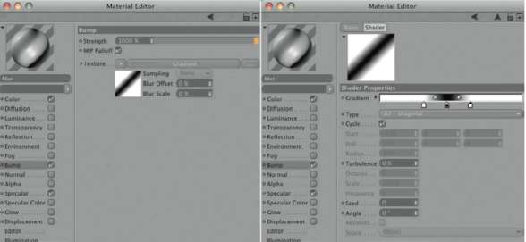
— Figure 1.24: A gradient helps with the visualization of the roughened handle structure.
The color tabs can simply be moved with the mouse. These positions can also be set numerically in the advanced settings by double clicking on the small triangle in front of the gradient, making these settings visible. New color tabs can be added with a mouse click directly under the gradient. Obsolete color tabs can be removed from the gradient by pulling them upward with the mouse. The color values of the color tabs can be edited in the advanced settings under the gradient or by opening the system color chooser and double clicking on the color tab.
The goal is to create a diagonal black line. In order to turn this line in a diamond pattern, the CYCle option has to be activated in the shader. It allows us to tile the shader, or repeat it multiple times, on the surface.
APPLYING THE MATERIAL
In order to increase the effect of the bump, we need to return to the level of the BUMP channel. To return, use the upward arrow in the upper right corner of the MATERIAL EDITOR or just click on the word BUMP in the channel list on the left side. Then increase the INTENSITY of the bump to 1000% using the STRENGTH value. Values above 100% can be entered directly in the numerical field. The slider itself can only go up to 100%.
ADJUSTING THE TEXTURE TAG
Pull the material from the MATERIAL MANAGER onto the handle cylinder in the OBJECT MANAGER. To make the projection onto the object easier, choose a projection type similar to the shape. In the TEXTURE TAG settings, which can be seen in the ATTRIBUTE MANAGER, choose CYLINDRICAL as the PROJECTION of the material. If you can’t see these settings, simply click on the small material symbol behind the cylinder in the OBJECT MANAGER. The size of the projection can be found and adjusted in the COORDINATES section of the ATTRIBUTE MANAGER.
If you prefer more visual options, then activate the USE TEXTURE TOOL mode. Make sure that the TEXTURE TAG behind the cylinder is active, which is indicated by the white frame around the symbol. This mode shows a preview of the projection in the viewports. A yellow grid indicates the size and position in 3D space. The common tools for moving, rotating, and scaling can be used to change the direction of the material projection.
In order to fit the projection to the dimensions of the object, use the FIT TO OBJECT command in the TAGS menu of the OBJECT MANAGER. In our case the corrugation is not supposed to cover the entire length of the handle, but only a part of it. We will look into that in a moment. First, we must determine the correct proportion of the bump so that the corrugation has the proper size and number on the cylinder.
The size, shape, and number of diamonds are determined by the size of the projection and controlled by the number of tiles in the TEXTURE TAG. As shown in Figure 1.25, I used 100 tiles in the X direction and 50 in the Y direction, with a Y length of the projection of 300 units. In addition, the options TILES and SEAMLESS need to be activated. The SEAMLESS option alternately mirrors the tiles and actually generates the diamond structure, since the gradient itself shows only a diagonal line. The alternate tiling of these lines to one another builds the diamond shape. By placing the INTERACTIVE RENDER REGION, which can be found in the RENDER menu in CINEMA 4D, over the cylinder in one of the viewports, we can easily follow the changes made by the number of tiles or the size of the projection. Figure 1.25 shows the desired result on the right.
RESTRICTING THE MATERIAL
Upon a closer look, we realize that when tiling the texture, the covered area became larger than the original area of the projection. Even when the area for the corrugation is defined by the Y length of the projection, the pattern continues beyond these limits. This is always the case when the TILES option has been activated. The preview of the
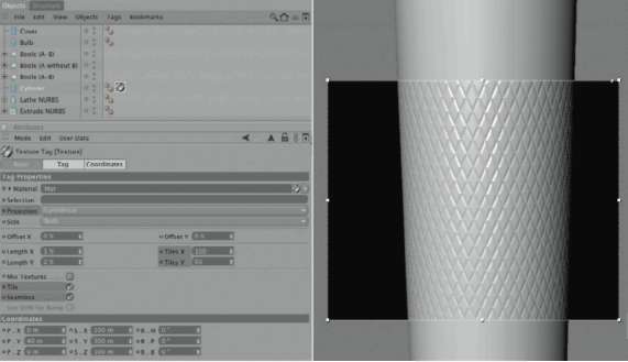
— Figure 1.25: The color gradient on the handle cylinder.
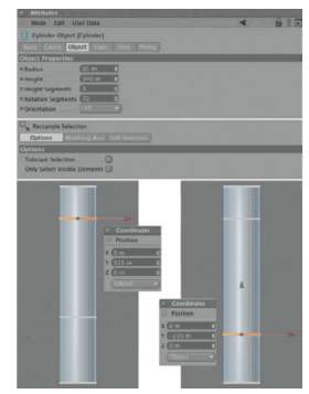
— Figure 1.26: Moving edges to define the area of corrugation on the handle.
projection in USE TEXTURE TOOL mode loses its function with regard to the area covered on the object. We can counteract this by creating a polygon selection. A scaled polygon strip on the cylinder has to be selected and a material applied to it. In the first step, increase the number of HEIGHT SEGMENTS of the cylinder to 3. This creates two additional SEGMENTS along its HEIGHT.
Now, we can’t avoid it any longer: we need to convert the cylinder to a POLYGON object so we can gain direct access to the points and faces of the cylinder. Press the (C) key and switch to the USE POINT TOOL mode. Use the FRAME SELECTION to select the upper of the two subdivisions. In the COORDINATE MANAGER enter the value 315 for the Y position of these points. Then press the (Enter) key or the APPLY button to actually apply this value. The points in the lower subdivision are to be changed in the same manner and moved to the Y position of 235. Both measures were applied in the OBJECT coordinate system of the cylinder. These steps are illustrated in Figure 1.26.
We will now switch to the USE POLYGON tool mode and use the RING SELECTION, in the SELECTION menu, to select the polygon strip that is between the two previously moved subdivisions. With the RING SELECTION tool activated, move the mouse over the middle polygon strip and click on it when the desired faces are highlighted. Then select Set SELECTION, also located in the SELECTION menu. This saves the information of the selected faces in a polygon selection tag, which then appears in the OBJECT MANAGER, behind the cylinder.
The selection tag becomes active when you click on it once. Its name can be changed in the ATTRIBUTE MANAGER and the saved selection can be accessed by means of several buttons. For applying a material, though, only the name is of importance. As shown in Figure 1.27, I used the name “grooved” and entered this name into the SELECTION field of the TEXTURE TAG. An even easier way is to simply pull the selection tag from the OBJECT MANAGER directly to the SELECTION field of the TEXTURE TAG dialog in the ATTRIBUTE MANAGER. From now on, the material will be restricted to the faces saved in the selection tag.
CREATING THE REST OF THE MATERIALS
All the remaining materials will not need visible structures and can be applied by a simple drag and drop onto the object. But first we
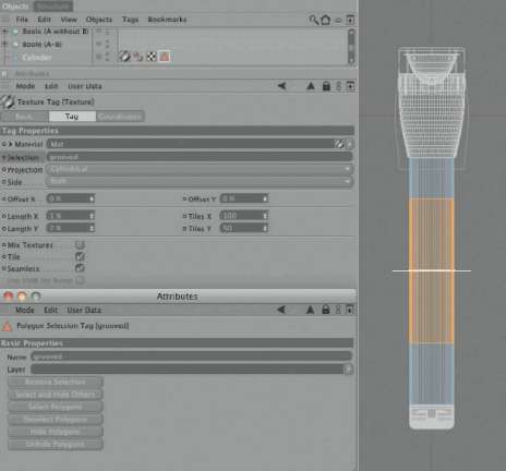
— Figure 1.27: Saving the point selection in a polygon selection tag.
need to finish the texturing of the flashlight handle. Open the material with the gradient in the BUMP channel using a double click in the MATERIAL MANAGER. Activate the COLOR channel by clicking on it in the channel list on the left. There, use a very dark and desat-urated blue. Metals generally have a very dark color.
Metals get their appearance more by way of their reflective properties, which we will now apply by using the REFLECTION channel. Activate the REFLECTION channel with a checkmark and set a slightly blue color with medium brightness. In order to make the metal appear less polished, increase the value for the BLURRINESS to 20%. This increases the render time but looks more natural for a basic commodity like a flashlight. The highlight should be relatively small but intense. This setting can be made with the HEIGHT and WIDTH settings in the SPECULAR channel.
Lastly, go to the ILLUMINATION channel and switch to the OREN-NAYAR MODEL. This increases the impression of a slightly rough surface. All these settings can be seen in detail in Figure 1.28. Use the same settings for a second new material that will be used for the head and bottom of the flashlight. No bump is necessary in these areas.
The Material of the Refector
The reflector is nothing more than a mirror. It often would be enough to just use a material with reflective properties and a highlight. But we have to keep in mind that there are not many objects, or even an environment, available around the flashlight. Even with high reflection values, not much would be reflected in the reflector. Consequently, we will use a trick and simulate a light reflection in the reflector by using additional material properties.
Create a new material that you could call REFLECTOR, and apply a strong REFLECTION of about 95% and a small intense SPECULAR. In addition, activate the LUMINANCE channel, set it to 50%, and reduce the color brightness of the COLOR channel to about 40%. Figure 1.29 shows all settings in detail. This causes the reflector to react, in addition to the reflection, to the incoming light and be brightened through luminance. We will see if all this looks as desired at the end, after the lighting is added.
The Glass Material
The material for the lens is structured in a simple way. One main part, of course, is a high brightness in the TRANSPARENCY channel. The EXIT REFLECTIONS option can be turned off since this doesn’t matter with such thin objects and would only use up valuable render time. A REFRACTION of 1.5 is enough for glass. In addition, I want to strengthen the reflective properties by activating the REFLECTION channel with a brightness of 100%. This

— Figure 1.28: The material of the flashlight.
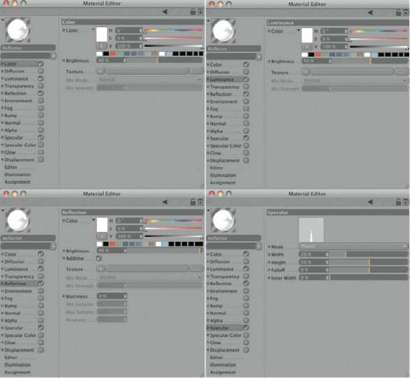
— Figure 1.29: The material of the reflector.
high value will be balanced by the strong transparency. The brightness of the color is reduced to 20%. I don’t use a highlight this time, since the reflector behind delivers enough brightness. All these settings are shown in Figure 1.30.
THE FLOOR IN THE SCENE
I want to add a floor to put the flashlight on so it doesn’t just float in 3D space. This floor should simply have a white color. We will create a new material and give it a brightness of 100%, as shown in Figure 1.31. The desired overall matte look is generated by the settings in the ILLUMINATION channel. We use again the OREN-NAYAR MODEL and increase the DIFFUSE REDUCTION value to 100%. This widens and diffuses the highlighted area on the object as seen at the preview sphere of the material.

— Figure 1.30: The material for the lens of the flashlight.
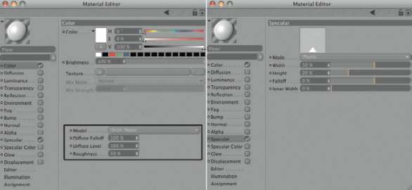
— Figure 1.31: The material for the floor.
Negative values can also be used when polished surfaces are portrayed. Then the brightness is more concentrated around the highlight and less scattered across the surface.
As the object for the floor, either a POLYGON or PLANE object could be used. However, in some cases it is better to use the FLOOR object since it has a special property. It automatically expands up to the horizon of the scene when rendered, actually becoming infinite.
We will add this FLOOR object, which can be found in OBJECTS>SCENE, and apply the previously created material to it. Don’t be fooled by the small square area in the viewport. The floor will cover the entire area of the scene after the image is rendered. The FLOOR object can also be moved and rotated just like any other object. Therefore, it can also be used for different purposes, like the roof of a very large hangar or the sky.
The parts of the flashlight should now get the appropriate materials. Simply pull the
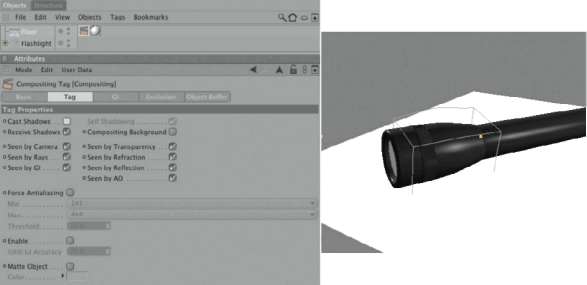
— Figure 1.32: The building of the scene with the flashlight on the floor.
materials from the MATERIAL MANAGER onto the respective object in the viewports or onto the names in the OBJECT MANAGER. Only the corrugated part of the handle that already has a material applied has to be treated differently.
Although the handle already has a material applied to it, the remaining faces have to receive a material as well. This is no problem, since an object can receive multiple materials. What is important here is the order of the materials behind the object in the OBJECT MANAGER. The material on the very top is always placed on the far right behind the object. This works just like a layer system. First pull the blue flashlight material WITHOUT the BUMP channel onto the handle cylinder. The corresponding TEXTURE TAG symbol will then appear to the right of the previously applied TEXTURE TAG of the corrugated part. The flashlight material now covers the corrugated material.
As a result, we have to change the order of the TEXTURE TAGS manually. Drag and drop in the OBJECT MANAGER in such a way that the material WITHOUT the bump structure is placed on the bottom, to the left of the corrugated material. Then group all the parts of the flashlight with a Null object. The fastest way to do this is to select all objects, except the floor, with a frame selection in the OBJECT MANAGER and then press the key combination (Alt) + G. This will group the selected objects under a Null object that can then be renamed to flashlight.
Then rotate and move the flashlight so it appears to lie on the floor. This can be seen in Figure 1.32 on the right.
The Compositing Tag
Many properties of the objects can be controlled during the rendering with a COMPOSITING TAG. We want to try this with the FLOOR object. Right click on the FLOOR object in the OBJECT MANAGER and choose CINEMA 4D TAGS>COMPOSITING TAG from the context menu.
The COMPOSITING TAG offers many options in the ATTRIBUTE MANAGER for determining how the object should behave in the scene later on. For example, the object could be set to invisible for the camera, yet remain visible in reflections or behind glass walls. Shadows could also be turned off, or the precision level for the global illumination or the edge smoothing could be altered. Other options adjust the calculation of individual alpha masks, like with the Multi-Pass rendering. In our case we just need to deactivate the shadows and the SEEN BY GI options. This will prevent the floor from participating in the global illumination.
The Light Sources in the Scene
Every scene automatically contains a light that can have its position adjusted in the display>DEFAULT LIGHT menu in every viewport. This light source is not suitable for the final lighting, though, since neither the INTENSITY nor the shadows can be edited. Therefore, we will place other light sources into the scene. As soon as a light is added to the scene the DEFAULT LIGHT turns off. In this case, I’d like to use a classic studio light setup with a main light and a fill light. Both lights should be AREA lights because these lights simulate a very realistic behavior. Real light sources also have a certain areal expansion and don’t consist of just a point in space.
I place one of the AREA lights, based on the view through the camera, behind the flashlight. This light is very intense and will also appear in the reflections of the flashlight by activating the SHOW IN REFLECTION option in the DETAILS section of the light source. The VISIBILITY MULTIPLIER will increase the reflection even more. Because this light is positioned right behind the flashlight I increase its INTENSITY manually to 200%. As with many parameters controlled by sliders, values larger than 100% can be set by entering them directly into the numerical field. The option for GI ILLUMINATION remains deactivated. Such an intense light would overpower the scene in a global illumination calculation.
It is also important to be sure that the floor isn’t affected by the light source; if it is, it would appear way too bright. Pull the FLOOR object from the OBJECT MANAGER into the OBJECTS list found in the SCENE portion of the light source dialog. With the MODE menu set to EXCLUDE, the objects listed will not be affected by the light source. The icons behind the listed objects, representing single attributes like highlight, diffuse illumination, or shadows, can be used to exclude certain attributes from this restriction. For example, if we deactivate the icon for the highlight by clicking on it, the object won’t be diffusely lit and won’t cast any shadows, but it would still have a highlight from the light source, provided of course that the material of the floor permits a highlight.
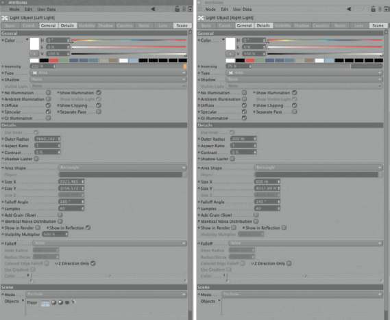
Figure 1.33 shows the settings of this light source in detail on the left. On the right are the parameters for the second light source. It is also an AreA light but with much less INTENSITY and WITHOUT reflective properties. Here we permit global illumination by activating the gi ILLUMINATION option.
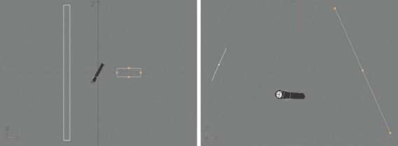
As for the positioning of the lights, just take a look at Figure 1.34. The intense and reflective light is positioned as a small strip to the left of the flashlight. The weaker fill light is opposite as a slim, vertical strip. These positions should be tested with test renderings or, even better, with the iNterACtive RENDER Preview to adjust them to your liking.
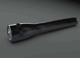
Figure 1.35 shows the desired effect after the rendering of the current viewport. I had set the ANti-AliASiNg to BeSt in the RENDER SettiNgS in order to be able to judge the effect of the bump material on the handle. I also activated the AMBieNt oCCluSioN in the RENDER SettiNgS to create shading in the area between the flashlight and the floor WITHOUT a real shadow generated by a light source. I increased the MAXiMuM rAY leNgth to 500 units, which is adjusted to the dimensions of our flashlight. A diSPerSioN of 80% restricts the scattering of the samples and thereby increases the contrast of the AMBieNt oCCluSioN at the edges.
I already like the INTENSITY of the reflection at the head of the flashlight. Only the overall brightness needs to be improved. This is the fault of the flashlight material, which mainly consists of reflective materials and reacts only slightly to diffuse illumination.
— Figure 1.33: The two AREA lights and their settings.
— Figure 1.34: The position and size of the two AREA lights.
— Figure 1.35: The effect of two light sources on the flashlight.
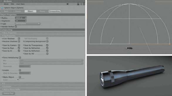
To add reflections to the upper part of the flashlight, an object has to be placed there. We are going to use a hemisphere that will hover over the scene. Create it by adding a sphere and changing the TYPE to heMiSPhere. Change the size and position so the two lights, and of course the flashlight, are located underneath the hemisphere, as shown in Figure 1.36.
Also apply a CoMPoSitioN TAG to the sphere object. We already used this tag to control the rendering of the FLOOR object. This time we will deactivate the CASt ShAdow and reCeive ShAdow options as well as the SeeN BY CAMerA option. Now the hemisphere can only be seen in the reflections of the flashlight and is not in the way when we look for the right camera angle.
Additionally, we need to deactivate SeeN BY Ao so the hemisphere is excluded from the AMBieNt oCCluSioN and does not create a shadow on the floor. All these settings can be seen in Figure 1.36, which also shows how much the rendering was improved. Because of the reflection of the hemisphere in the metal of the flashlight, the surface shading appears much brighter and more vivid.
— Figure 1.36: The same scene after adding a dome.
— Figure 1.37: Getting the light bulb to glow.
Lighting with Global Illumination
To simulate the switched-on flashlight, we could place a spotlight on the reflector and adjust its opening angle to the WIDTH of the lens. We can go a step further, though, by using global illumination. Not only does this define the light bulb itself as the light source, but also the indirect light and the light reflected from the hemisphere will enhance the look of the image.
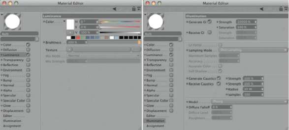
In order for the light bulb to emit light, it has to receive a material with illuminating properties. Also, the INTENSITY for the global illumination and the SAMPliNg MODE has to be defined on the ILLUMINATION page. The size of the object plays a part, too. The smaller an object, the more illuminated it has to be to create an illumination effect. Thus, in the case of the light bulb, I have to use extreme values like 10000% for the geNerAte gi STRENGTH and 300% for the SAturAtioN, as shown in Figure 1.37. These values are multiplied to define the actual illumination strength.
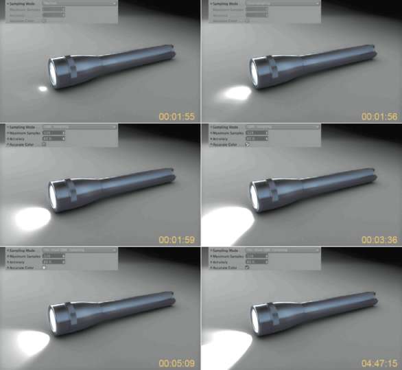
The SAMPliNg MODE in illuminating materials defines how they are sampled during the global illumination calculation. Figure 1.38 shows a visual comparison of the light bulb material and the results after activating the global illumination and changing the SAMPliNg MODE. It also lists the render times, showing how increasing the sample accuracy has a direct influence on the render time. We have to find a compromise between quality and render time here. Keep the SAMPliNg MODE overSAMPliNg for now and apply the material to the light bulb by pulling it onto the CAPSULE object in the OBJECT MANAGER.
USING GI PORTALS
A gi PortAl is an object that lets GI rays pass WITHOUT using render time to do so. This is helpful when light shining through a window is supposed to illuminate a room. The window glass would then be such a GI portal. In our example this property would apply to the lens because the light bulb beneath is supposed to send its rays out into the scene.
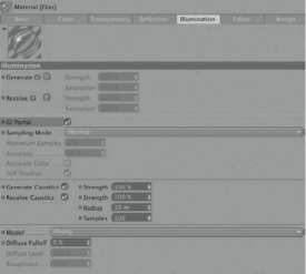
For that purpose we open the glass material again and go to the illumination setting, as shown in Figure 1.39. As you can see, I completely deactivated the generating and receiving GI properties. The more transparent a material is, the less it benefits from global illumination. Therefore, we can do WITHOUT it here and save some render time. The gi PortAl option also bundles the calculation rays of this object since—as the name Portal indicates—a passing of light through the object is expected.
— Figure 1.38: Comparison of the different sampling modes of the light bulb material and the resulting render times.
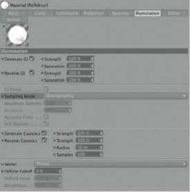
The reflector material also has illuminating properties. Here the SAMPliNg MODE controls the evaluation of this object during rendering by global illumination. Since this object doesn’t affect the illumination of the scene as much as the light bulb, we can use the relatively fast but also softly interpolated overSAMPliNg. Figure 1.40 shows these settings again.
— Figure 1.39: The lens and its illumination settings.
— Figure 1.40: Changing the sample mode of the reflector material.
THE RENDER SETTINGS FOR GLOBAL ILLUMINATION
Despite the wealth of possible settings for global illumination, CINEMA 4D makes it easy for us since we only see the fine adjustments when we actually need them. First select gloBAl ILLUMINATION from the list of effects and then decide on the GI mode for the rendering. The QMC mode is very precise but needs a lot of samples to achieve a minimum amount of noise and is therefore too slow for a high-resolution image. The irrAdiANCe CAChe, on the other hand, looks for image areas that need more samples than other parts and then interpolates between the different levels of brightness. It is quite fast and delivers an almost noise-free result. The down side is that small DETAILS get lost during the interpolation. Regardless, this mode is the best choice in most cases because calculation data can be saved and loaded, making global illumination in animations usable. Since we have a still image, we ought to choose the ir (SiNgle iMAge) mode and leave the diFFUSE dePth at 1 with a PriMArY iNteNSitY of 100%. That means the light will bounce only once from another surface. This should be enough, since we also have traditional light sources in the scene that aid with the illumination. The other settings in the irrAdiANCe CAChe section remain at their standard settings.
I also activated the glow effect, as shown in Figure 1.41. This effect can be found in the list of all PoSt effects by clicking on the eFFeCtS button. It superimposes a light halo on all light places in the image and by doing so softens the image, making it look more natural. Such image manipulation can also be done in postproduction. The base parameters of the glow effect are the size and INTENSITY of the effect. Both depend on the size of the rendered image and are difficult to estimate. Therefore, test renderings using the final size of the image are necessary. This is another reason to create such effects in postproduction.
You can also see the described settings of the AMBieNt oCCluSioN in Figure 1.41. I have, based on the color of the flashlight, set the color value at the right edge of the gradient to a dark blue so the simulated shadow underneath the flashlight doesn’t appear too dark and is better integrated into the overall image. The last thing to do is to enter the desired render resolution into the outPut section and the file path in the SAve section of the RENDER SettiNgS, and to start the rendering in the PiCture viewer. The result of my rendering can be seen in Figure 1.42.
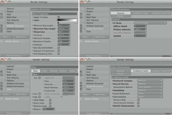
— Figure 1.41: The render settings for the flashlight scene.
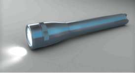
— Figure 1.42: The rendered image with global illumination and glow effect.
Modeling with the HyperNURBS Object
So far we have only used NURBS objects as help objects that can generate POLYGON objects out of spline curves. The HYPERNURBS object is different from the other NURBS objects since it needs a POLYGON object to actually do something. It is quintessential for modeling rounded objects. The HYPERNURBS is able to subdivide and automatically place these subdivisions to make the object look rounded.
A Short Example
A short example will clarify its abilities. Create a primitive cube and add two SEGMENTS in the X direction and two in the Y direction in the ATTRIBUTE MANAGER. Then change the Z size to 100 units and convert the cube using the (C) key. Change into USE POINT TOOL mode and select all points that are located to the left of the center of the cube in the front viewport. Delete these six points by using the (Delete) key. Make sure that the mouse pointer sits over one of the viewports. Otherwise, when the pointer is located over the OBJECT MANAGER, the (Delete) or (Backspace) key then DELETEs the whole object and not just the selected points. Figure 1.43 shows the desired state of the object.
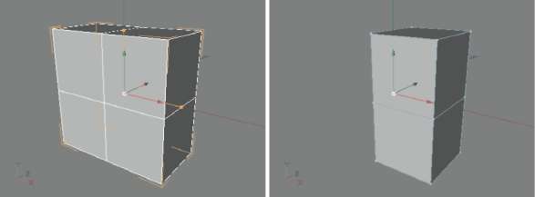
— Figure 1.43: A cube is converted and cut in half by deleting some points.
In the next step, select the lowest four points and scale them along the Z direction to about one-third of the original distance between them. Then move the points of the half cube as shown in Figure 1.44. Can you guess what the final shape will be?
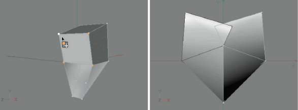
The shape should look like a stylized heart by now. Make sure that the four points on the lower left edge of the shape remain exactly on the ZY plane. We will want to amend the left side of the heart with a SymMetrY object. The SYMMETRY object combines points that are located exactly on the mirror plane. This is an important feature to ensure that the original and the copy will fit together seamlessly.
In a moment the HYPERNURBS will automatically subdivide and smooth the roughly modeled shape. This can only be done, however, with a completely closed volume. Open edges remain sharp after the HYPERNURBS rounding. Accordingly, we close the upper four points along the open side of the former cube with a square.
MANUALLY GENERATED POLYGONS
Make sure that you are still in USE POINT TOOL mode and then select CreAte POLYGON in the StruCture menu of CINEMA 4D. By clicking on a series of points, this tool allows the creation of a new polygon between them. To make a triangle, single click on the first two points and double click on the third. A quadrangle is built with three single clicked points and one double click on the fourth point.
Planes with more than four points, so-called n-gons, are also possible. Just single click on all points along the edge and create the face with a double click on the last point. The tool can be deselected by selecting another tool, such as the MOVE tool. Keep in mind that the points will be connected in the order they were clicked on. Therefore, get into the habit of clicking clockwise or counterclockwise. The left side of Figure 1.45 shows the desired result.
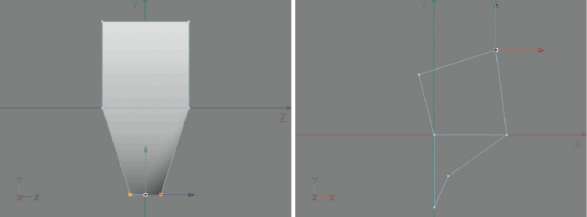
— Figure 1.44: Moving the lower points together along the Z axis and the shaping of the remaining points.
— Figure 1.45: Manual closing of the upper faces and completion of the shape with a Symmetry object.
ALIGNING THE NORMALS
The direction in which the points were clicked also determines indirectly the alignment of the normals on the polygon. When polygons are created manually, it is often the case that the normal of the face has a different alignment from the rest of the object. This can be recognized by the different tint of these faces in the viewports. In this case, use the AligN NORMALS command in the FUNCTIONS menu of CINEMA 4D. Make sure that no polygons are selected when this function is selected, or switch for a moment to USE MODEl tool mode. This way the command affects all the faces and not only the currently selected ones.
If you are sure that there is only one face with the wrong alignment, then it can be selected directly and changed with reverSe NORMALS, found in the FUNCTIONS menu. Lastly, add the SYMMETRY object and subordinate the former cube in the OBJECT MANAGER. The right side of Figure 1.45 shows the result in the front viewport.
— Figure 1.46: The HYPERNURBS generates an interactive smoothing of the subordinated geometry.
THE HYPERNURBS SMOOTHING
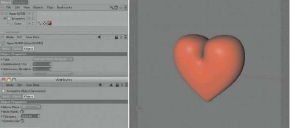
After subordinating the SYMMETRY object under the hYPerNURBS object (you can find it in the OBJECTS menu under NURBS), a small miracle occurs. The previously angular structure is now smooth and rounded, as you can see in Figure 1.46. This effect can be set separately in the ATTRIBUTE MANAGER for display in the viewport and renderer. The higher the SuBdiviSioN value, the more faces are generated and used to smooth the object.
Be careful! Every increase of just 1 unit results in a quadrupling of the faces and also increases the memory use. The subdivision for the editor is generally much smaller than for the renderer, since we need the best possible quality for the final rendering. In the editor it is more important to be able to work efficiently with the object. This would be more difficult to do with the display of so many faces in the editor.
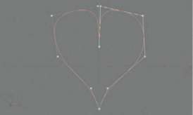
If you have difficulty getting used to working with the HYPERNURBS object, take a look at the difference between a linear and a B-spline. The principle is identical, as can be seen in Figure 1.47. The B-spline uses the straight SEGMENTS between the tangents of a rounded curve. The curve doesn’t pass through the points but instead has a soft curvature. This principle can be compared to HYPERNURBS smoothing except it isn’t a curve being rounded but instead a three-dimensional surface.
— Figure 1.47: Two identical splines, one with a linear interpolation and the other with a B-spline interpolation.
Also keep in mind that the structure of the added and rounded faces looks different with triangular faces than it does with quadrangular-shaped ones. Therefore, you should work with only quadrangular faces on POLYGON objects whenever possible. Otherwise, the triangles could cause some visual irregularities on rounded surfaces. This rule can be ignored when an area is supposed to be exactly within a plane. In this case only, triangles and n-gons don’t cause any problems and can be used WITHOUT influencing the roundings on the object.
Modeling a Carabiner
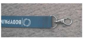
For this example we will use a photo of a small carabiner (as shown in Figure 1.48) as our template. This ensures that we keep the approximate dimensions and it helps with placing the geometries more exactly.
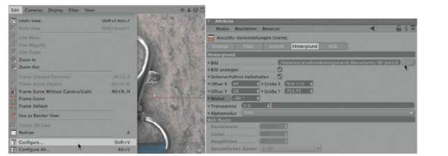
You can load images in any of the isometric viewports: the front, side, or top view. In this case, use the edit menu in the front viewport and select Configure.
In the settings of the ATTRIBUTE MANAGER you can also find a Back tab. A click on the button with the three dots opens a window where you can load any type of bitmap. Depending on the size and orientation of the image you can now rotate, scale, and move it to a different location within the viewport. Because of the orientation of the image we have to rotate it by -90°, as shown in Figure 1.49. The settings for the size and position of the image in the front viewport depend on your individual preferences. By and large you don’t have to change anything here
— Figure 1.48: The carabiner to be modeled, at the end of a keychain.
MODELING THE UPPER LOOP
We will start the modeling at the fixed top curve of the carabiner and then continue downward. In a second step we will model the gate, and last is the mounting for the key ring. Again, we will use as many basic objects as possible to reduce the manual modeling. You will also learn about some new polygon tools such as the knife and the extrusion tools.
The easiest way to start is with a bent cylinder at the upper part of the carabiner. Add a CYLINDER primitive and set the RADIUS to 10 and the HEIGHT to 250 units. These values depend on the scale of your background image. Adjust your radius so it approximately matches the thickness of the gate in your image. When in doubt increase the radius since the geometry will shrink a bit when the HYPERNURBS smoothing is applied. Eight SEGMENTS are enough for the circumference. The smoothing will be done later with a HYPERNURBS object. Because the cylinder is supposed to be bent we will need additional SEGMENTS along its HEIGHT. I prefer to work with 10 SEGMENTS. The cylinder should also stand vertically, so use the +Y direction in the settings of the cylinder in the ATTRIBUTE MANAGER.
— Figure 1.49: Loading the image into the background of the front viewport.
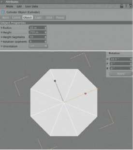
Since we have to split the carabiner into two halves at the base—the movable gate has to be added there—it makes sense to rotate the cylinder around the vertical axis so one face of its circumference is placed vertical to the symmetry axis. For a better understanding, take a look at Figure 1.50. Rotating the vertical cylinder by 22.5° places a face, when seen from above, left, and right, onto the WORLD X axis. When these faces are DELETEd, the cylinder will be divided into two pieces where we need to insert the gate. Lastly, deactivate the option for the creation of caps at the cylinder. What is left is a thin-walled pipe.
— Figure 1.50: A slim cylinder is the start object.
Bending the Cylinder
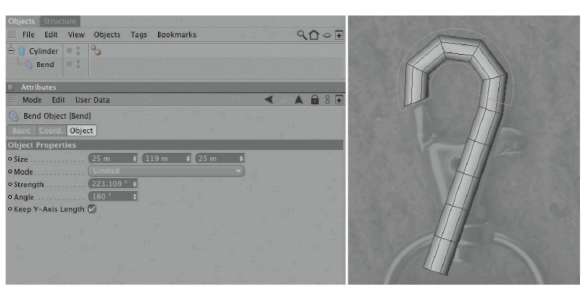
Rotate the cylinder in the front view so it is slightly tilted to the right. Use the outer edge of the carabiner as a guide that runs from the lower base at the right side of the carabiner in the direction of the gate. The area over the gate then transforms into a curve. This bend can be created with a Bend deformer, which is a child of the cylinder. Correct its local H rotation in the Coordinate Manager to -22.5°. The Z axis should now be vertical to the front viewport. The P and B angles are set to 0°. The Y part of the position will be determined in a moment.
In use MODEl tool mode, pull the orange handler of the deformer—in the front viewport—with the MOVE tool to the right, so the upper part bends according to the image in the background. Since the radius of this bend is determined by the Y length of the deformer, you have to adjust it so the result looks like the one in Figure 1.51. There you can also see the settings I’ve used for the deformer.
By moving the deformer along its Y axis we can define the starting point of the bend. If the cylinder is too short at the upper end, use the use object Axis tool mode to move the cylinder with the MOVE tool further up along its Y axis. The position of the Bend object is not changed by this move.
This is a specialty of the parametric objects since they are constantly calculated based on their position. When we move the local axis system of these objects, the location of the objects in 3D space is automatically changed as well, but the child objects remain at their original location.
— Figure 1.51: The desired bend in the cylinder is created with a Bend object.
Converting a Deformation
When you are happy with the result, then you have to further edit the cylinder at the point level. As you already know, we have to first convert the parametric cylinder into a Polygon object. But when deformers are used this cannot be done with the Make editable function or the (C) key. This would make the cylinder editable, but wouldn’t include the deformer in the calculation of the point positions. In these cases we need the Current State to object command in the Functions menu of CINEMA 4D. It will include the deformation in the current state of geometry as well as conversion of the primitive into a Polygon object.
This creates in the object Manager a new Polygon object including the editable geometry of the bent cylinder. The original Cylinder object, including the deformer, can now be DELETEd. Switch to the use Point tool mode and activate the live Selection. Make sure that the selection of hidden points is possible. Since we work entirely in the front view, it is important to also select the points in the back of the object because they have to be moved as well.
Start by selecting the points at the lower left edge of the converted cylinder and adjusting them with the MOVE tool to the left edge of the carabiner in the background image. The left part of Figure 1.52 shows the desired result. The points of the cylinder that might be positioned below the visible base can be selected and then DELETEd with the (Delete) key.
The Knife Tool
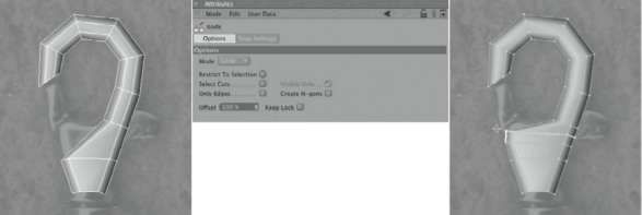
In order to better model the area of the base that creates the lower edge of the carabiner, we need more points in this area. So we will, for the first time, use the knife tool, which, like almost all other Polygon tools, can be found in the Structure menu of CINEMA 4D. As the name of the tool suggests, the knife cuts through polygons and adds new points and polygons by doing so—a very useful tool to add selective subdivisions. After selecting the knife, as with most tools, some settings appear in the ATTRIBUTE MANAGER, as seen in the center of Figure 1.52. Several modes allow us to cut, by dragging the mouse, along a line or along a plane that runs parallel to the WORLD coordinates. In our case we will select the looP mode. It automatically makes the cut through a series of neighboring faces. A highlight function shows the course of the cut to be made in the editor before the cut is made by a mouse click.
— Figure 1.52: Converting the cylinder and subdividing it with additional cuts.
Deactivate all options in the knife dialog, since we want neither to restrict the cut to only selected elements nor to generate n-gons. The latter would create new points at the edges and also fill the cut faces with n-gons. These types of faces should be avoided, though, when using HYPERNURBS smoothing, since they don’t give us any control over the internal interpolation of the n-gon faces.
Now move the mouse pointer, with the activated kNiFe tool, over one of the outer vertical lines of the carabiner. You will see a highlighted line that adjusts itself based on your mouse movement and indicates the course of the cut. When you like what you see, make a mouse click to apply the cut. For a more precise preview, push the (Shift) key while the preview of the cut is still highlighted. Then you can position the cut with the oFFSet function in the ATTRIBUTE ManAger. A mouse click in the editor then makes the cut.
Two horizontal cuts at the spot where the gate enters the base should generate enough points to further adjust the shape to the image. Select and move the new points on the left side of the model to align them with the loaded background photo. The right side of Figure 1.52 shows the state of the model up to that point.
The Shaping of the Base
To shape the upper part of the base, we can’t use the technique of horizontal cuts. We will need more subdivisions that run vertically through the base. Bear in mind, though, that we are dealing with slightly bent parts and should avoid using triangles. Remember, triangles are subdivided differently at Hyper-NURBS smoothing and could look funny in combination with surrounding quadrangles.
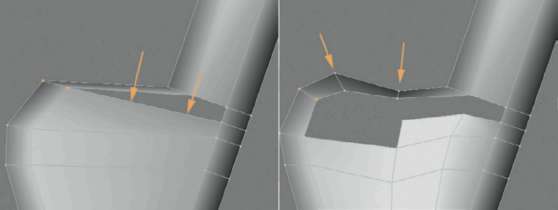
We should use only quadrangular subdivisions and pay special attention to the possible connection points. Therefore, we will DELETE a face for the moment, as shown on the left of Figure 1.53. A simple selection of the face in USE POLYGON tool mode and use of the (Delete) key will take care of that. Simply DELETE the visible face in the front viewport. The back of the deformed cylinder will be replaced anyway and can be disregarded.
The two diagonal arrows shown in the figure indicate where the two loop cuts should be added. The right cut continues the subdivision of the upper cylinder at the base. In the next step we will create a connection point at the upper edge of the base.
— Figure 1.53: Additional steps make it possible to shape the base.
— Figure 1.54: Manual closing of the open areas at the base of the carabiner.
First, though, DELETE another polygon, as shown on the right in Figure 1.53. The arrows there point to another two cuts that should be executed in looP mode. Use the added points along the upper edge of the base to shape the desired course, following the background image.
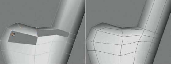
In USE POINT TOOL mode activate the CreAte POLYGON tool in the StruCture menu and create the left face, as seen in Figure 1.54, by consecutively clicking on the four corner points. Double click on the last point to close the face. Remember to not click randomly on the points but to select them clockwise or counterclockwise. Do the same with the remaining three faces until the base is closed, as shown on the right side of Figure 1.54.
To eliminate incorrectly aligned normals use AligN NORMALS in the FUNCTIONS menu. When you are in USE POLYGON tool mode, make sure that no faces are selected. Otherwise, the function would be restricted to the selected faces. In that case use deSeleCt All from the SELECTION menu.
Creating the Hole in the Base
In the center of the base there is a hole that goes all the way through. It will contain a riveted pin that will later hold the movable part of the carabiner. Such holes could be created with a BOOLE object. This method generates too many faces, though, and can not be used because of the resulting uncontrolled generation of triangles in the BOOLEd area, which would create unexpected results during the HYPERNURBS smoothing. Therefore, we will choose another way.
— Figure 1.55: The contours for the hole are built by extruded inner faces.
First activate the X-rAY mode for the deformed cylinder object. This option can be found in the basic settings of the cylinder in the ATTRIBUTE MANAGER. The object will then have a slightly transparent appearance in the viewports and will allow the background image to shine through in the front viewport. This way it is easier to compare the center and size of the hole with our model.
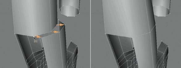
First, place the point located closest to the center of the hole as exactly as possible at the center, as shown on the top right of Figure 1.55. Then change to USE POLYGON tool mode and select the four faces surrounding this point. To generate additional faces within polygons, which can be used to model the edge of the hole, use the EXTRUDE INNER command from the StruCture menu.
As you hold down the mouse button in the front viewport and move it to the left and right, new polygons are created in the same plane as the previously selected polygons. As an alternative, you could use the oFFSet value in the ATTRIBUTE MANAGER and then the APPLY button in the tool section of the dialog when you wish to use a certain value. This is not necessary in our case.
Back in USE POINT TOOL mode, use the new points to shape an octagon around the center of the hole to indicate the desired opening. Remember that the HYPERNURBS object will take care of the smoothing in this area, too, so don’t be bothered by the angular look of the shape. The lower two images in Figure 1.55 show these steps.
Modeling the Inside of the Base
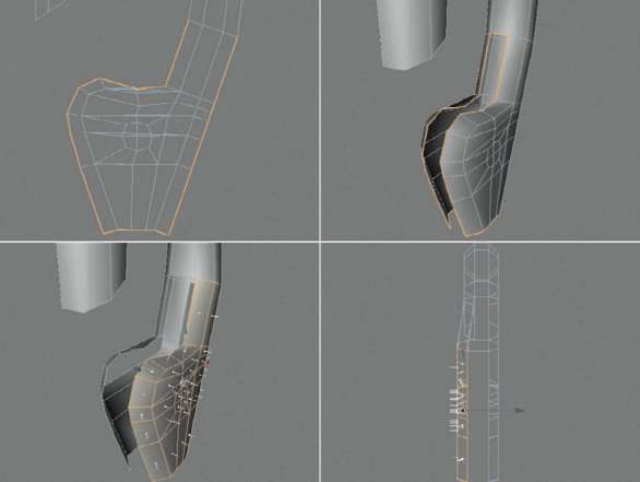
As already mentioned, we took these steps only in the visible part seen in the front viewport. The rear of the object will now be DELETEd and then replaced by the mirrored part of the remaining object. First we make sure, by deleting some polygons, that the base underneath the branching of the upper arm is split into two halves.
The upper images in Figure 1.56 show this area of the opening with a highlighted frame.
Then we select the faces at the front of the base, seen in the lower left of Figure 1.56, and move them along the WORLD Z axis. The image on the bottom right in Figure 1.56 shows the side of the model and the approximate size of this movement.
The reason for this movement is to create more space between the halves of the base so that the arm of the movable part of the carabiner can be inserted later.
— Figure 1.56: Parting the two sides of the base by deleting polygons.
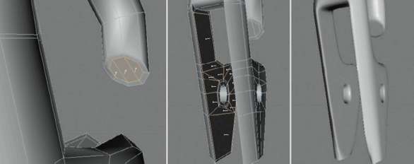
The corresponding faces that form the back of the base and that were not moved can now be DELETEd. Figure 1.57 shows the desired state of the object in the side view. Now we will close the inside of the base and implement the hole as an actual opening. In the first step we will use the CreAte POLYGON function in the StruCture menu and close the areas with four quadrangles, as shown in the center top in Figure 1.57. Select the four quadrangles that mark the hole in the center of the base and choose the eXtrude command in the StruCture menu.
Extruding Faces
The eXtrude command doubles selected faces and moves the duplicates along the normal direction by any given amount. This allows us to extend or split objects. It is, along with the knife and the previously used EXTRUDE INNER tool, one of the most-used tools.
Its function is similar to the EXTRUDE INNER tool. First select the face, then choose the eXtrude tool and move the mouse, while holding the mouse button, to the left or right in the editor. Here you could also work with numerical values in the ATTRIBUTE ManAger, in case the movement of the duplicated faces has to be a certain amount. Again, this is not important to us. Just use the state of the object in the upper right image of Figure 1.57 as a guide.
— Figure 1.57: Extrusion of the hole.
You can see there that the faces were first extruded by a small amount in the direction of the rear of the base, and then to a larger degree. This is done by moving the mouse just a small bit while holding the mouse button, then letting go, and immediately holding the mouse button again. The mouse movement will then generate another face. That way, several extrusions can be created in succession WITHOUT having to select the tool again. The short extrusion and the resulting close edges will cause less rounding and a more defined edge when HYPERNURBS smoothing is used. In the side view make the extrusion in such a way that the new faces align approximately with the open edge at the sides of the base. Then DELETE the extruded polygons so an octagonal opening is created, as shown on the bottom left in Figure 1.57. You can also see that we now have to select the edges of the newly opened tunnel. Therefore, change to USE edge tool mode and choose the looP SELECTION in the SELECTION menu. This selection tool can automatically select neighboring elements.
Choose the option SeleCt BouNdArY looP in the settings of the looP SELECTION in the ATTRIBUTE MANAGER. Now when you place the mouse pointer over an edge of the opening, the faces should be highlighted and can be selected by a single mouse click.
Extruding Edges
We again activate the eXtrude function in the StruCture menu, since it works not only with faces but also with edges. Also here you can duplicate and move the edges by holding the mouse button and moving the mouse in the editor. Doing this creates new faces along the previously open edge of the structure—a good technique for expanding flat objects at their edge. To position the new faces vertical to the tunnel, take a look at the ATTRIBUTE MANAGER. As long as you don’t execute another function or select another tool, the values of the last used tool can be seen and changed.
You can change the WIDTH of the extrusion with the oFFSet value or control the angle of the newly generated faces with the edge ANgle parameter. A value of –90° should ensure that the new faces are placed exactly vertical to the inner tunnel faces. The lower images in Figure 1.57 show the desired result.
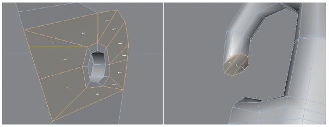
In USE POINT TOOL mode, select the CreAte POLYGON tool in the StruCture menu and create the faces, shown highlighted in Figure 1.58, that close the inner area of the base and the end of the upper arm. You can see at the base that some triangles were used, too. They were used because the location of the points relative to each other doesn’t restrict us to the exclusive use of quadrangles. It doesn’t matter that much in this case since all these faces are located in a plane and the HYPERNURBS will not have to calculate a bend for these faces. So in this special case it is okay to mix triangles and quadrangles, WITHOUT worsening the result, as we will see later.
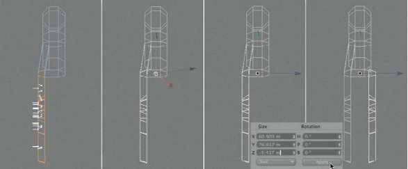
Now it is time to add the missing rear half of the base. It is the exact mirror image of the front half, thus saving us the time of having to model it. First, in edit POLYGON tool mode, select the polygons of the completed front half of the base. The best way to do this is to select them in the front view with live SELECTION, where the selection of hidden faces is enabled, since all faces are supposed to be selected. The selected area can be seen on the very left in Figure 1.59.
Then select the diSCONNECT command in the FUNCTIONS menu. It duplicates the selected faces and copies them into a new object, leaving the original object unchanged. The coordinate system of the original is transferred to the copied faces as well. The necessary faces have already been duplicated and just need to be mirrored to the other side of the carabiner.
— Figure 1.58: Manual closing of open areas.
— Figure 1.59: Separating and mirroring polygons.
This mirroring should be done along one of the axes. Currently, though, the axis system of the disconnected faces is slightly twisted, as can be seen in the second image from the left in Figure 1.59. This can be easily corrected in the USE OBJECT AXIS tool mode. Just reset the three rotAtioN values in the COORDINATE MANAGER to 0 to bring the axes back into a neutral position. This does not change the position of the axis system, which is a good thing because it is positioned exactly in the middle of the former cylinder and therefore on the desired symmetry plane.
Now change to the USE MODEl tool mode and add a negative sign in front of the Z size of the object, created by the diSCONNECT function, before you use the APPLY button of the COORDINATE MANAGER. A negative size results in the mirroring of the geometry along the corresponding axis, as we can see in the very right image of Figure 1.59. The disconnected faces were mirrored to the rear side of the carabiner.
Connect and Stitch
The mirrored faces are in the right place but are still a separate object and have no connection to the main model of the carabiner. We will now fix that. Select the model of the carabiner and the model with the recently copied faces with a (Ctrl) click in the object Manager and choose Connect in the Functions menu. This will create a new object containing the faces of both models. The two old objects can now be DELETEd.
The closing of the gap at the end of the bent cylinder loop will be done with the Stitch and Sew command. It is located in the Structure menu of CINEMA 4D. It is very important that no points of the object be selected. Otherwise, this tool would affect only these elements. Switch to use Point tool mode and use the deselect All command in the Selection menu before you start Stitch and Sew. The stitching itself is shown symbolically in Figure 1.60. First, click on the point that is supposed to snap to the other, and while holding the mouse button, pull a line to the point across. After you release the mouse button, the point will snap to and be combined with the other point. This results in the generation of a complete symmetry and not just two points on top of each other. When you are finished stitching all the points between the loop and base together, the static part of the carabiner is almost done.
By looking diagonally into the gap of the base, from below, you can see a spot where a polygon is missing, right where the two halves of the base meet the upper loop. You can either close this hole manually with a quadrangular polygon by using the Create Polygon tool or use the Close Polygon hole command. Select the latter one in the Structure menu and move the mouse pointer to the edge of the hole until a virtual face appears at that spot, bridging the gap. A mouse click then creates this polygon. The left image in Figure 1.61 shows this face.
HYPERNURBS Smoothing
Now we will use the HYPERNURBS object. Select it in objects>NURBS and make the polygon model of the carabiner a child of this new HYPERNURBS object in the object Manager. Instantly, the angular model transforms into a softened organic object, as seen in detail on the right side of Figure 1.61.

— Figure 1.60: Stitching snaps points to one location and merges the geometry at the same time.
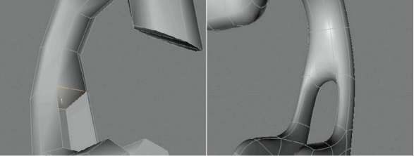
— Figure 1.61: Bridging the two halves and smoothing the geometry.
The rounding is partially too strong so the desired angular or mechanical look gets lost. The reason for this is that any place where edges are spaced too far apart, the Hyper-NURBS has too much space to round the area. The radius of the rounding becomes too large and the shape gets too soft. This can be corrected by adding subdivisions in areas where the model should be more angular.
The first area will be the transition between the loop and base. To change the opening to a more angular one we have to select the kNiFe tool in the StruCture menu and activate the looP mode. Figure 1.62 shows the correct cut in the left and center image. First, create a looped cut slightly above the spot where the shape splits. Two additional cuts close to the connection point of the front and rear base parts make the shape look perfect. The result of these three cuts can be seen at the far right in the figure.
At flat and plane areas of the model we can use the EXTRUDE INNER command. This method also creates new edges that, when placed close together, severely restrict the rounding properties of the HYPERNURBS. We can use the command at the end of the upper loop and inside the base. Select the polygons shown in Figure 1.63 and select the EXTRUDE INNER command in the StruC ture menu. Either use the mouse inside the editor or enter a small oFFSet value directly in the ATTRIBUTE MANAGER, which is then executed with the APPLY button. Figure 1.63 shows on the far right the effect of this action. The edited areas are now flat and less rounded at the edges.

— Figure 1.62: Additional subdivisions force the HYPERNURBS into a more angular shape.
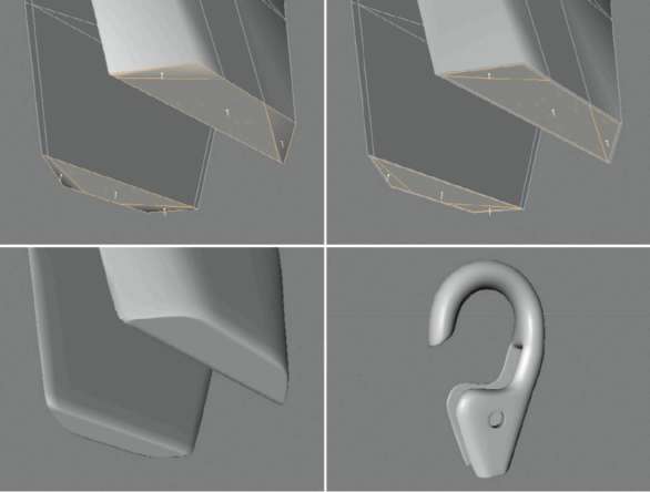
— Figure 1.63: Extrude Inner creates new subdivisions within the flat areas and also a hard edge at the HYPERNURBS smoothing.
Since we started with a cylinder WITHOUT caps, we now have to close the open areas at the bottom of the base. The points on the edge of these holes should be at the same position on the WORLD Y axis and on the same plane. Use the looP SELECTION with activated SeleCt BouNdArY looP option to select the points, then correct the Y position in the COORDINATE MANAGER to 0. The COORDINATE MANAGER should be set to WORLD mode for this step. Then use the CreAte POLYGON function in the StruCture menu to create the three faces. Here too the use of triangles will not be a problem, since the area is a plane. The created faces on both sides of the base are then selected again, duplicated once with StruCture>EXTRUDE INNER, and shrunk by a small oFFSet value, as shown in Figure 1.64. This will result in a defined hard edge in the HYPERNURBS smoothing at the bottom of the base. This part is now complete.
MODELING THE MOVABLE GATE
The movable gate of the carabiner closes the gap to the upper loop and sticks out of the carabiner as a lever. The gate is attached in the middle by an axis pin and fixated by a small spring. We will begin the modeling of this part with the creation of two cylinders WITHOUT caps, as can be seen in Figure 1.65.
These cylinders will receive eight SEGMENTS along their circumference and rotate 22.5° around the Y axis. Base this on the Cylinder primitive from which we modeled the fixed carabiner part. Then rotate the two cylinders in the front viewport so they follow the V shape of the base. Afterward, bend the thinner of the two cylinders with a Bend deformer so that it emerges from the carabiner at the proper spot on the right side. The measurements and the position of the cylinders can be seen in Figure 1.65.
Converting and Connecting the Objects
Use the Make editable function or the familiar (C) key on the thicker left cylinder to create an editable Polygon object. The thinner cylinder is influenced by a deformer and thus has to be converted with FUNCTIONS>CurreNt StAte to OBJECT. The original with the subordinated BeNd deformer can then be DELETEd. In the USE POINT TOOL mode you can now further edit the two shapes. The left cylinder is slightly bent by moving the upper points and the wider cylinder is thickened at the end, as can be seen in Figure 1.66. The two objects can’t remain separated and have to be connected; therefore, select the two cylinders and choose CONNECT in the FUNCTIONS menu. A new object appears in the OBJECT MANAGER. The original models of the separated cylinders can now be DELETEd.

— Figure 1.64: Closing and Inner Extrude of the lower openings at the base.

— Figure 1.65: Building the movable gate of the carabiner from two cylinder primitives.

— Figure 1.66: Converting the two cylinders and preparing them for the connection.
To create a real connection between the two cylinders, change to the USE POLYGON tool mode and select the six faces that are across from each other at the lower part of each cylinder. Figure 1.66 shows these areas in the center and right image.
The Bridge Tool
This job is perfect for the Bridge tool located in the StruCture menu. It creates connections between selected faces and DELETEs the original faces. Change to USE POLYGON tool mode, select the Bridge tool, and place the mouse pointer on one of the corners of the selected polygons. Hold down the mouse button and move the mouse pointer to the opposite polygon corner. The left image in Figure 1.67 depicts the movement of the mouse symbolically with an arrow.

— Figure 1.67: Connecting faces with the Bridge tool.
After releasing the mouse button, all previously selected faces are DELETEd and new faces are created for the connection, as shown in the center of Figure 1.67. Of course, we could have done this manually with the CreAte POLYGON tool, but this way it is much faster. Note that the Bridge tool also created faces at the bottom of the model, as shown on the right in Figure 1.67. We don’t need these faces and can DELETE them.
Adding New Subdivisions
In the center part of the movable gate we now have to create a hole for the pin and some space for the small spring that holds the bar in place when closed. First use the kNiFe tool in the StruCture menu and activate the looP mode. The remaining options in the kNiFe dialog remain deactivated. Add the three cuts that are marked in the left part of Figure 1.68. This will add more points at the upper edge of the bar and more subdivisions at the base.
Before we use these new points to shape the model, change to edit POLYGON tool mode and select the front faces of the base in the front viewport. The right part of Figure 1.68 shows these faces in a different color and how to handle them. These faces have to be moved along the WORLD Z axis toward the rear of the gate. The center becomes thinner and creates some space for the still missing models of the pin and the spring.
This part will be smoothed later by a HYPERNURBS. Therefore, we can keep the special requirements of this smoothing in mind by closing the remaining open areas and creating additional edges where a hard edge, despite the smoothing, is supposed to remain visible. We will use the CreAte POLYGON tool in the StruCture menu of CINEMA 4D. Close the two ends, located on top and on the right of the former cylinders, with three quadrangles each, as shown in Figure 1.69.
As you can see in the figure, the new faces at the upper end of the left cylinder were selected, duplicated with the eXtrude tool in the StruCture menu, and shrunk by a small amount. You already know this principle from the base and the upper loop of the stationary carabiner model. In the left part of Figure 1.69 there is a correction of a point position, indicated by an arrow, so the right part of the gate keeps its thickness up to the constricted part.
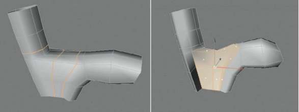
— Figure 1.68: Adding new subdivisions with the knife and constricting the shape in the center.
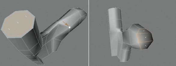
— Figure 1.69: Closing the open ends.
Modeling the Opening for the Pin
The following principle is the same as the one we used at the base of the stationary carabiner piece to model the hole for the pin. Here, too, select the four faces surrounding a point in the center of the gate and use the EXTRUDE INNER command to duplicate and shrink these faces. In USE POINT TOOL mode use the newly created points to shape the round opening, modeling it after the hole in the carabiner base. These steps are shown in the images of Figure 1.70. Remember also that this time our model has a rear side that has to be treated in the same way. Consequently, make sure that, before you select the four faces for the inner extrusion with the live SELECTION tool, you deactivate the oNlY SeleCt viSiBle eleMeNtS option. The rear faces will then be extruded as well. The best way is to work exclusively in the front viewport when selecting and moving the points and faces. That way you can be sure that the points at the rear side are selected and moved correctly as well.
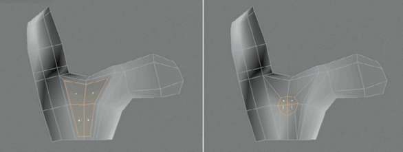
— Figure 1.70: Adding new faces with Extrude Inner to create an opening.
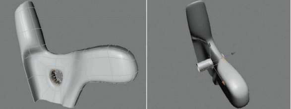
— Figure 1.71: Creating a connection with the Bridge tool and making the pin cylinder.
The adjusted faces that cover the opening now have to be connected to generate the opening. We already know how to use the tool for the connection of selected faces, the Bridge tool in the StruCture menu. But it is more difficult this time since we can’t see both faces at the same time. Therefore, select the perspective viewport and switch to a display mode that makes it possible to see the opposite side’s selected faces through the model. A good mode to use is the liNe setting in the diSPlAY menu of the editor view.
Then, while holding the mouse button, pull a connection line between the selected faces in front of and in back of the gate. After releasing the mouse button, an octagonal breach should be created, as can be seen on the left side of Figure 1.71. Into this opening place a new CYLINDER WITHOUT caps. The number of circumferential SEGMENTS doesn’t have to be changed since this cylinder will not be smoothed with a HYPERNURBS.
Finishing the Pin
Scale and place the cylinder so that it protrudes only a small amount from the front and back of the base, as shown on the left in Figure 1.72. For a better view, the pin cylinder is highlighted in another color. Then create a new RING object, which can be found in the primitives of CINEMA 4D. Reshape it so the ring can be put at the open edge of the pin cylinder, like the end part of a rivet. Figure 1.72 shows my settings and the desired effect of the highlighted ring on the carabi-ner model.
Now create a duplicate of the ring by pulling it with the mouse while holding the (Ctrl) key in the OBJECT MANAGER, or by copy and paste. MOVE the duplicated ring to the other open end of the pin cylinder. This anchors the pin at both ends of the carabiner.
The Spring of the Gate
Between the gate and the carabiner itself there is a simple spring at the pin. It will be created with a heliX spline that already exists as a parametric object and can have its parameters adjusted in the ATTRIBUTE ManAger. With the PLANE setting of XY you will put the spline into the same orientation as the pin. Then adjust the position of the spline and the two RADIUS values in the heliX dialog so the position as well as the size fit to the size of the gate pin. It is helpful to blend out the rigid gate model in the editor to get a better view of the inner parts of the carabiner.
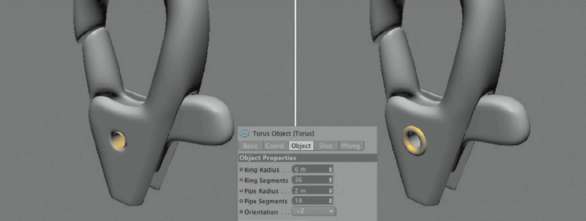
— Figure 1.72: Fade the ends of the pin cylinder into ring objects.
With STARt ANgle and eNd ANgle you can control the number of desired windings as well as the position of the open ends of the heliX. With the HEIGHT value you can control the distance between the windings. This setting is best made when the heliX spline is subordinated, together with a CIRCLE spline, as children of a SweeP NURBS. Make sure that the CIRCLE spline is placed in the XY plane and subordinated directly under the SweeP object so it is used as the profile. Then adjust the HEIGHT and RADIUS of the profile circle so a spring-like shape is created. My settings and the desired look are shown in Figure 1.73.
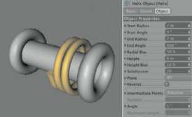
— Figure 1.73: Simulating the spring shape with a Helix spline.
In order to move the ends of the heliX to the desired position in the model to complete the spring, the heliX spline first has to be converted. Before you do so, take a look at the SuBdiviSioN value in the dialog of the heliX spline. It determines how many points the helix is supposed to have after being converted into a normal spline. Since we have only a few windings of the heliX, the value of 100 is too high and would generate way too many points. Reduce the SuBdiviSioN to a value of about 20 before you use the (C) key.
Then switch to the USE POINT TOOL mode and select and move the two end points of the heliX as shown in Figure 1.74. The short end nestles up against the protruding ridge of the movable gate and the longer end leans on the middle part of the carabiner at the spot where the opening for the gate is located.
THE LOWER PART OF THE CARABINER
The carabiner and all the interior components are now complete. The only part missing is the connection piece on the bottom for the key chain. We can use primitives exclusively and finish this part quickly. However, there is one other property of primitives we have not talked about yet.
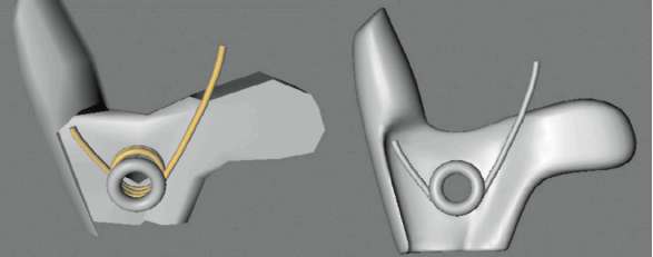
— Figure 1.74: Manually placing the ends of the helix.
Distorting Primitives
Perhaps you thought during the modeling that it would be nice to be able to unevenly scale a primitive object, for example, to flatten a sphere to a lens or to model a cylinder with an elliptic profile. This is not a problem as long as the primitive is converted first, but then it loses all its parametric properties such as the ability to be rounded.
There is a way to get around that, though: switch to USE OBJECT tool before scaling the primitive object. This mode is similar to the USE MODEl tool mode but with the difference that the axes are scaled instead of the points the object is made of. We can also see this in numbers in the COORDINATE MANAGER when we look at the size of the object. The standard is one unit in each direction, since it represents the length of the local axes system. But when we scale in USE OBJECT tool mode these values change.
We will use this mode now since the ring that has the hoop of the key chain attached is not supposed to be perfectly round. Figure 1.75 shows the desired shape of the new RING object. By scaling along the X axis in USE OBJECT tool mode the ring was widened by 18% in the X direction. Otherwise, you can orient the size and position of the ring on the loaded background image in the front viewport.

— Figure 1.75: Scaling primitives unevenly.
The Lower Connection of the Carabiner
The next steps are less interesting since all you have to do is complete the model with three Cylinder primitives that will be scaled and intersected so they become the pin that connects the carabiner to the previously distorted ring. Figure 1.76 shows the three new cylinders with the ring in the center. Remember to round the cylinders at their caps so a highlight will appear at their edges later.
This, however, does not apply to the slim, vertical cylinder that passes through the ring. It doesn’t need any caps since its ends disappear within the other two cylinders.
The Lower Hoop of the Carabiner
The only thing missing is the hoop of the distorted ring object through which the key chain band is pulled. We will start with a Circle spline that is scaled and placed as shown on the very left of Figure 1.77. The Circle has to be converted to a normal spline with the (C) key so we can switch to use Point tool mode, move the lowest point of the circle upward, and adjust the tangents at the two lateral points so the desired hoop shape is achieved. The desired shape is shown in the center of Figure 1.77. You can see the desired result on the right side where the modified spline and another small Circle spline were subordinated under a new Sweep NURBS object. Again, make sure that Circle spline is used as the profile is placed on the XY plane and that it is placed highest in the list under the Sweep NURBS.
We are now finished with the modeling of the carabiner. I would like to take a small excursion into the WORLD of XPresso so you can experience the practical use of this graphical programming part of CINEMA 4D.
Making Models Move with XPresso
XPresso is the graphical programming part of CINEMA 4D. It is used when several parameters are supposed to be combined or when object movements should be automated. With the example of the carabiner, I would like to show you the basic steps of using XPresso. You will get to know its use of so-called user data as well as the connection of parameters. At our carabiner the act of opening and closing could be used for such an expression since we have a limited opening radius of the bar and the spring that is supposed to follow. The spring is the most complex part of this chain and therefore we will take care of it first.
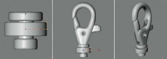
— Figure 1.76: Three cylinders in different sizes complete the model.

— Figure 1.77: The lower hoop is made from a converted Circle spline.
Fixate the Ends of the Spring
The shape of the spring is determined by a spline. We are mostly interested in the ends of the spring since they have to remain fixated at the gate as well as at the stationary part of the carabiner, even when the gate is rotated. Basically, our job is to stabilize the two end points of the spring spline to a fixed location in 3D space. First we will add two Null objects from the OBJECTS menu of CINEMA 4D and move them to the current position of the two end points.
Interactive Snapping
This could be done by manually transferring the point position of the spline to the Null objects, but it is easier to use the snap function. This function is activated by pressing the (p) key. A snapping context menu appears, as can be seen in Figure 1.78. In the upper part you can select the desired snapping method and underneath, the elements to snap to. Since the context menu closes after every mouse click you might have to use the (p) key more often until all settings are made.
The snapping methods are 2d SNAPPING, which snaps optically according to the current viewport, 2.5d SNAPPING, which only snaps when the elements are positioned on the same plane, or 3d SNAPPING, which snaps the objects in all three directions. After choosing the mode you have to select whether you want to snap to points, splines, or axis systems. Several elements can be combined. In our case we want to snap to the end points of the helix spline. Therefore, you should activate 3d SNAPPING and POINT SNAPPING. The other options that are activated by default can remain that way. Make the objects not relevant for this step invisible in the editor for a moment and deactivate the Sweep NURBS of the spring by clicking on the green checkmark in the OBJECT MANAGER in order to have a clear view of the spline.
In USE MODEl tool mode, first move the one Null object close to the one end of the heliX spline until it snaps to the point. Then do the same with the second Null object and the other end of the spline. Give the Null objects meaningful names such as Mount Up and Mount Down to be able to tell them apart.
Don’t forget to deactivate the snapping so the objects can be moved freely again. Use the (p) key again and choose No SnapPiNg in the context menu. Then subordinate the Null objects, as shown in Figure 1.78. The Null object at the end of the movable gate is subordinated under the model of the gate in the OBJECT MANAGER. The other Null object can remain at the highest hierarchy level. For a better overview, all objects should be grouped. Choose SeleCt All in the edit menu of the OBJECT MANAGER and use the key combination (Alt)+(g). As an alternative, you could also select grouP OBJECTS from the OBJECT menu in the OBJECT MANAGER. The new Null object containing all objects can be renamed carabiner and expanded again by clicking on the plus sign.
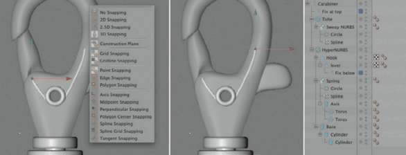
— Figure 1.78: Place two new Null objects at the end of the helix spring.
Creating an Expression
The goal of our first expression should be to attach the ends of the helix to the positions of the two Null objects at all times. This would mean that the spring would follow the rotation of the gate since the corresponding Null object moves with the gate.
First, right click on the new carabiner Null object in the OBJECT MANAGER and choose CINEMA 4D TAGS>XPreSSo from the context menu. The XPreSSo editor, in which we can now assemble our expression, opens automatically. You can pull materials, tags, and objects directly from the different managers into the XPreSSo editor. This generates so-called NodeS, which allow you to request data or to set values.
We will try this by pulling both Null objects, which hold the helix ends of the model and the Helix spline itself, one by one from the OBJECT MANAGER into the XPreSSo editor. This creates the nodes of these objects. The nodes have a blue and red area in the top left and right corners. Blue represents the input and red the output of the node. A click on these areas will open a list with all the available parameters of the node. For the following expression we need the position in the WORLD coordinate system of both Null objects. On the red output side activate the output for gloBAl PoSitioN. The input and output of the nodes are also called PortS.
To transfer the position of the Null objects to the corresponding points of the Helix spline, an intermediate step is necessary because the coordinates of the helix end points cannot be assigned directly to the node of the Helix spline. This requires a so-called POINT Node. It can be created by right clicking in the empty area of the XPresso Editor. In the appearing context menu, select New Node>XPreSSo>geNerAl>POINT. You can see in Figure 1.79 that there are many nodes available, sorted by themes, which can be used to make certain mathematical calculations or to simulate simple program structures like loops or if requests.
The Point Node
The POINT node is helpful when requesting point coordinates from POLYGON objects or splines, or to provide points within these objects with new coordinates. Therefore, this node needs to get the following information: the object being affected, the point being targeted, the kind of coordinate system (object or WORLD system), and, when defining a point coordinate, its position within 3D space as a vector. The object being affected is clear, but which points will be affected? Let us take a look at the StruCture ManAger, which is grouped with the OBJECT ManAger. It contains a tabular list of all points of the spline, including their coordinates and tangents. they can be directly edited with a double click on the numerical values. This is very helpful for the exact positioning of tangents. If you don’t see the list of points in the StruCture MANAGER, ensure that the Helix spline is actually selected and the POINT MODE is activated in the MODE menu of the StruCture MANAGER. As you can see by the other modes in the menu, this manager can also be used to show polygons or UVW coordinates. This list shows us that, in our case, the first point has the number 0 and the last point the number 20. These point numbers are also called iNdeX and can be assigned directly to the point node so it knows which point needs to be affected.
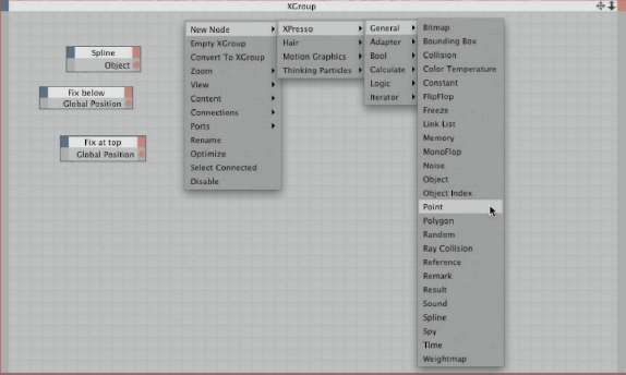
— Figure 1.79: The XPresso Editor.
Because we want to influence two points, the two end points of the spring spline, we need two point nodes. So create a second point node and take a look at the ATTRIBUTE MANAGER. As shown in Figure 1.80, the index number can be entered directly in the PArAMeter section. The MAtriX MODE menu allows us to choose between global and local coordinates. We will select the global mode for both point nodes because this simplifies the assignment of the coordinates. Otherwise, we would have to convert the position of the two Null objects to the coordinate system of the helix, which could only be accomplished with a matrix calculation.
After the index 0 is assigned to the first point node and the index 20 to the other point node, the nodes have to be told which object and coordinate will be used.
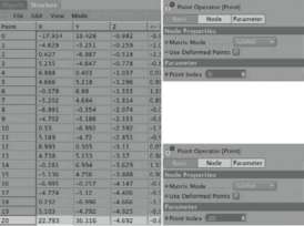
— Figure 1.80: Configuring the point nodes.
Connecting Nodes
We get this information directly from the Null object and the Helix spline node, which are already part of the expression. As you can see at the input port side of the point node, we are asked for an object. We get this information from the output port of the spline node. Click on the red area of the spring node and select the object port. Then click onto the new red circle, which represents the port on the right side, and, while holding the mouse button, pull a connection line to the object input of the point node. This has to be done twice to get the object information to both point nodes.
The lines between the nodes are called connections. These connections transport the data from one node to another, in this case, the object information from the spline to the point nodes. Now we have to send the two global positions of the Null objects to the point nodes. First, click on the output port of the node representing the Null object at the movable gate of the carabiner. Hold the mouse button and pull a connection line to the blue area of the point node that stands for the point index 0. In my scene this is the index number of the spline point ending at the gate. When you release the mouse button, the input side of the point node unfolds and shows you all the available ports. Select the port for the point position, and the connection between the two nodes is automatically made. Do the same to the second Null object node and the corresponding point node, as shown in Figure 1.81. This completes the expression, and the XPreSSo editor can now be closed. As you might have noticed, a new tag appeared behind the carabi-ner object in the OBJECT MANAGER after the expression was created. You can open the XPreSSo editor again with a double click on the tag to further edit the expression.
Working with User Data
To make the expression work, we need a control element that we can use to rotate the gate of the carabiner. USEr dAtA can be used for this purpose. It is used to create your own dialogs and their entries become part of the expressions. User data can be assigned to any tag or object in the OBJECT MANAGER. The type of object doesn’t affect the functionality. Choose an object that you have easy access to, even within collapsed hierarchies. In our case that would be the carabiner Null object. When you select it you might notice the USEr dAtA menu in the ATTRIBUTE ManAger. Select MANAge USEr dAtA and a menu opens, as shown in Figure 1.82. With the Add button you can generate a new entry that can be substantiated on the right side of the dialog. First, give this entry a useful name under which this parameter will appear later in the ATTRIBUTE MANAGER, such as oPeN. The next decision pertains to the dAtA TYPE of the parameter. Is it supposed to be text, a color, or even a drag and drop field for an object? In our case we will use a numerical value, the FloAt. The look of the parameter in the ATTRIBUTE MANAGER is controlled by the iNterFACe setting. In the case of the float data type, it could be the FloAt Slider, an entry field with an attached slider. Then we have to determine the type of uNit, such as angle, meter, or percent. I decided to use Percent. A value of 100% would then represent a completely open carabiner and 0% a closed one.
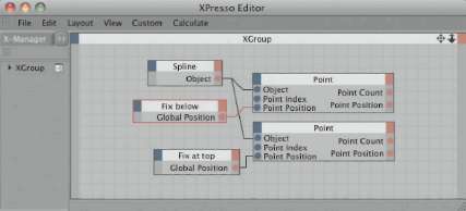
— Figure 1.81: Connecting nodes.
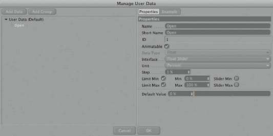
— Figure 1.82: Creating user data.
The following settings for Step, Min, and Max define the range for the numerical entry. The step value sets the range of the numerical steps executed when the small arrows behind the number field are used. I kept it at 1% and set the Min value to 0% and the Max value to 100%. Now everything is set and the dialog can be closed with the ok button. Now there is a new section in the ATTRIBUTE MANAGER called user data containing your custom parameters. The value can be edited by entering a number or moving the slider, but it doesn’t affect anything yet. We first have to connect this new value with another parameter. In our case this would be the rotation angle of the gate object of the carabiner.
Requesting User Data in XPresso
Select the carabiner object again in the Object Manager, right click on it, and choose CINEMA 4D tags>XPresso. Now pull the carabiner Null object from the object Manager into the new XPresso editor. This Null object carries the user data value that we want to request and converts it into the rotation of the gate.
— Figure 1.83: Requesting user data.
With a click on the red area of the carabi-ner node in the expression, we gain access to the USEr dAtA of this object and therefore also to our Open parameter, as can be seen in Figure 1.83.
The range of the Open parameter is between the extremes of 0% and 100%, as we have defined before. This represents a float value between 0 and 1. The entry of 76% is equal to the numerical value of 0.76. This value is supposed to be converted to an angle value that is then transferred to the gate object of the carabiner. For these kinds of jobs we will use the rANge MAPPer node, which can calculate the rule of three. Right click in the XPreSSo editor and choose New Node>XPreSSo>CAlCulAte>rANge MAPPer.
The rANge MAPPer compares a received value with the range between two preset values. These two threshold values are defined in iNPut lower and iNPut uPPer in the ATTRIBUTE MANAGER. In our case, the iNPut lower is the value 0 and iNPut uPPer represents the value of 1, since our user data values will be within this range.
The settings outPut lower and outPut uPPer define how the received value is supposed to be recalculated. For example, if we set the outPut lower to 0 and outPut uPPer to 5, then a user data value of 50% would result in a Range Mapper result of 2.5, exactly half of the range between 1 and 5. Because we want to calculate an angle, change the outPut rANge menu to degree. This is important since all angles otherwise have to be entered as radians in XPresso.
First, check whether the local axis system of the gate is actually centered, since this will be the gate’s pivot point. For changes, switch to USE OBJECT AXIS tool mode and use the MOVE tool to place the axis system into the right position. The angle values should all indicate 0° in the COORDINATE MANAGER. Back in USE MODEl tool mode, the gate should now rotate correctly in the carabiner. You can reset the gate again to the neutral and closed position with a numerical entry of 0° for the angle in the COORDINATE MANAGER.
With my model I can rotate the movable gate by 46.5° around its Z axis until it touches the inside of the carabiner. Depending on the tolerance during modeling your angle could be slightly different. This angle should be transferred to the gate when the user data value is set to 100%. The 46.5° has to be entered into the outPut uPPer field in the dialog of the Range Mapper in the ATTRIBUTE MANAGER. If you don’t see this dialog, click once on the title bar of the rANge MAPPer mode in the XPreSSo editor.
Now pull the movable gate object directly from the OBJECT MANAGER into the expression and activate the port for rotAtioN.B at the blue input side of the node. It can be found in the menu of the blue area in the section COORDINATES>rotAtioN. Now connect the ports as shown in the center of Figure 1.84: the output of the carabiner node with the input of the Range Mapper and the output of the Range Mapper with the input of the gate node. You should already be able to rotate the gate by changing the user data value of the carabiner.
Don’t forget the spring on the inside of the carabiner, since it will be turned as well. Pull the former Helix spline into the expression and also activate an input port for the rotAtioN.B value, which represents the rotation around the Z axis. The ends of the spring are already fixated to the model by the other expression, but the windings will also turn slightly on the axis when the cara-biner is opened. Thus add another range Mapper to the expression. The quickest way is to (Ctrl) drag and drop the existing Range Mapper directly inside the XPresso Editor, the same way objects are duplicated in the object Manager.

— Figure 1.84: Range mapper nodes convert the user data to angles.
Make the same settings at the new Range Mapper as before, but use only half the angle for the output uPPer value since the spring rotates only half as much as the gate. In my case I entered an angle of 23.25°. The connection works the same way as before and can be seen in Figure 1.84. The function of the expressions is now complete and the XPresso editor can be closed.
Adjusting the Priorities of Expressions
After you have played a bit with the Open user data value and activated a transparent or wireframe display of the objects in the editor, you might notice that the ends of the spring have a slight delay at the rotation of the carabiner gate. This is because we have two expressions that request interacting values from each other. One expression rotates the gate and the spring with the user data value, and the other expression requests the position of the subordinated Null object of the gate and aligns the end point of the spring spline to it.
Since all expressions are executed at the same time or WITHOUT a certain order, occasionally an expression uses old position or rotation values before they are updated by the other expression. In such cases, the PrioritY of an expression is used. It is set in the PrioritY menu of the BASIC ProPertieS settings of the XPreSSo TAG in the ATTRIBUTE MANAGER. There you can find basic groups of priorities like iNitiAl, eXPreSSioN, or geNerAtorS. But since the execution of objects and deformers in CINEMA 4D itself follows such priorities, you can determine at what point an expression is supposed to be executed. In the highest priority geNerAtorS you can be sure that when you ask for deformed point coordinates in XPresso, you will always receive the up-to-date values.
The following numerical value sorts the priority within the chosen group. The higher the number, the later the calculation will occur. That way you can force an order over time of several expression tags within the same priority group. In our case, the standard priority eXPreSSioN is enough, as we only have to control the order of the execution of the two XPresso tags.
As we can see in Figure 1.85, in our example it is best to leave the priority of the expression for the rotation of spring and gate at 0, and to elevate the expression of the following points to PrioritY 1. This is enough to set the points after the rotation of the gate and to remove the delay.
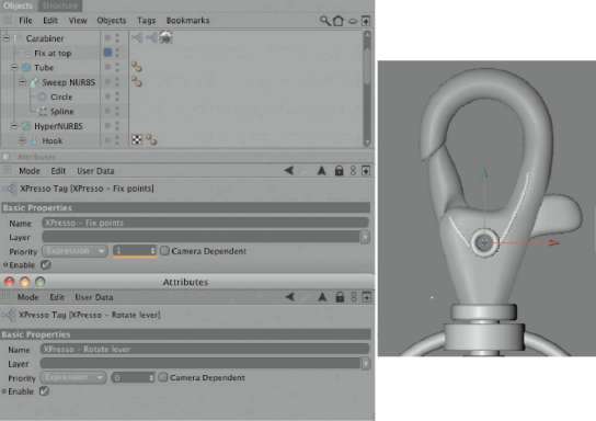
— Figure 1.85: Adjusting the priorities.
Now the carabiner is finished and can easily be moved with the user data value of the carabiner object, as shown in Figure 1.86. Especially when setting up animations, such expressions can save us a lot of work since complex relations between objects can be controlled by using just one value.
PUTTING THE CARABINERINTO A SCENE
We have come so far now that we might as well add some fitting materials and a scene as well. We will start with the metal material of the carabiner and create a new standard material in the MATERIAL MANAGER with FILE>New MATERIAL, which can be edited in the MATERIAL EDITOR by a double click on the gray preview sphere.
The Lumas Shader
Metals are generally very dark but have high gloss and reflective properties. The gloss is controlled entirely by the Specular channel of the material. More control and additional effects are only possible with the lumas shader. Therefore, we load this shader into the COLOR channel by clicking on the small triangle in the texture section. The lumas shader is part of the eFFects group.
The lumas shader makes it possible to choose one base color and up to three individual highlights. Especially interesting is that the shader is able to add anisotropic effects as highlight distortion to its calculations. They appear when a surface contains very fine ridges. Just think of the surface of a DVD or human hair, which show such effects as well because of their rough surface.
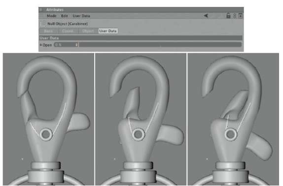
— Figure 1.86: The complete carabiner and easy control with user data.
This effect offers two separate settings, one for the distortion of the highlights and the other for generating visible ridges within the highlights. The latter can make the surface appear like brushed metal WITHOUT having to use specially adjusted images.
In our case we will first use a dark gray in the ShAder ProPertieS of the luMAS shader and exchange the red tones of the highlights with pure white ones. The brightness and size of the three highlights remain the same. Now activate the aforementioned ANiSotroPiC section and use the Auto PlANAr projection mode. This mode controls the direction of the highlight distortion and can often be checked only on the object with test renderings. The projections with the term Radial in front are able to generate concentric grinding patterns like the ones used for decoration on old refrigerators or other special surfaces. Their effect is very pronounced when used together with the ridges.
The amount of highlight distortion through the anisotropic calculation is controlled separately for each direction with the X Roughness and Y Roughness. The highlight options beneath determine which of the three highlights will be distorted. You can anisotropic-distort only one highlight, while the other highlights will be calculated in a concentric manner. We will keep everything active so all highlights will be distorted, as shown in Figure 1.87.
After the dividing line in the dialog you can find the values for amplitude, size, and length of the anisotropic scratches. Also, here the effect can be restricted to only one highlight or, like in our case, can be deactivated altogether. We don’t need this effect since our carabiner is not supposed to appear scratched or rough, but instead perfectly smooth.
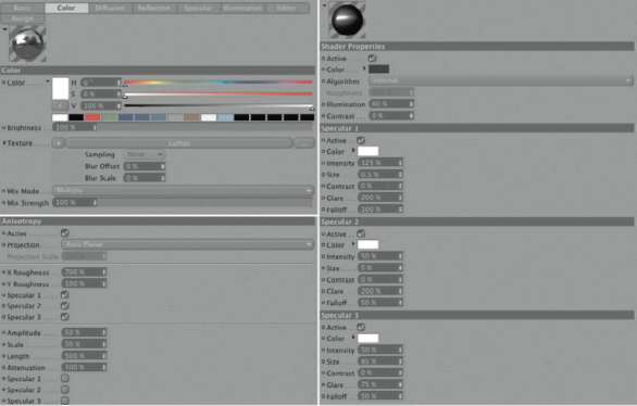
— Figure 1.87: The settings of the Lumas shader.
Ambient Occlusion as Shader at Material Level
In the flashlight example, we got to know Ambient oCClusion as an effect in the render Settings. It is used to naturally darken objects in areas where folds or the proximity of another object would restrict the amount of light. This effect can also be applied to certain materials with the Ambient oCClusion shader, which helps to save some render time and to simulate different tints or detail levels on various objects.
Generally, the diFFusion channel is the right place for this shader, which can be found, like the lumas shader, in the eFFects shader group. I’ve kept the settings of the shader the same except for the dispersion, which I changed to 70% to generate more contrast. Test renderings later will show whether the effect has to be increased or decreased. It is important in our material, which is mainly determined by its reflection, that in the diFFuse channel the option Affect reflection is activated. It already affects the COLOR channel WITHOUT us having to do anything. Figure 1.88 summarizes the settings in the diFFusion channel and in the Ambient occlusion shader.
The settings for the reflection of the material don’t give us any surprises, as Figure 1.89 shows. I used a high Brightness of 90% and didn’t increase the Blurriness value since I wanted to depict a perfectly polished surface. This also saves us some render time.
The FLOOR in the Scene
The carabiner shouldn’t just hover in 3D space, but should lie on the floor. The floor shouldn’t compete, by way of its color or brightness, with the mostly gloss-defined carabiner. Thus I will create a new material and apply a very dark red tone, as shown in Figure 1.90. Again, I loaded the AMBIENT OCClUSION shader into the DIFFUSION channel. The settings are the same as in the carabiner material, which is why I didn’t show them again in the figure.
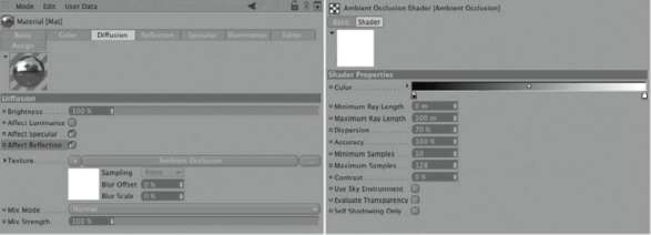
— Figure 1.88: Using Ambient Occlusion as a shader.
— Figure 1.89: The reflections of the carabiner.
I also activated a weak reflection of 7%, which is softened heavily by the BLURRINESS effect of 20%. The SPECULAR is wide and very flat. I also used the oreN-NAYAr model for the shading in the ILLUMINATION settings. This will generate soft shading on the floor. The settings for the brightness of the color and the INTENSITY of the highlight are so weak because I want to illuminate the carabiner with a very bright light from diagonally behind the object, creating a sharp highlight and strong contrast. At the same time, the floor shouldn’t be brightened.
The Light Source
I decided to use a spotlight since I can align the light precisely and control it with the light cone. As already mentioned, I’ll overdo it on purpose with the INTENSITY by setting its value to 800%. The spotlight will not cause a shadow. Place the spotlight at the side of the carabiner, with the protrusion of the gate, which is in the upper right based on the viewer’s location.
Aligning the Light Source
Light sources can be easily aligned by using them as a camera. Just activate the light in the object Manager and then select link Active object in Cameras>Scene Cameras of any viewport. You can then use the common icons for moving or rotating the camera, in the upper right corner of the viewport, to navigate the light source and align it to the rear of the carabiner. When you are finished, use the editor CAMerA entry in the CAMerAS menu of the viewport to separate it again from the light source.
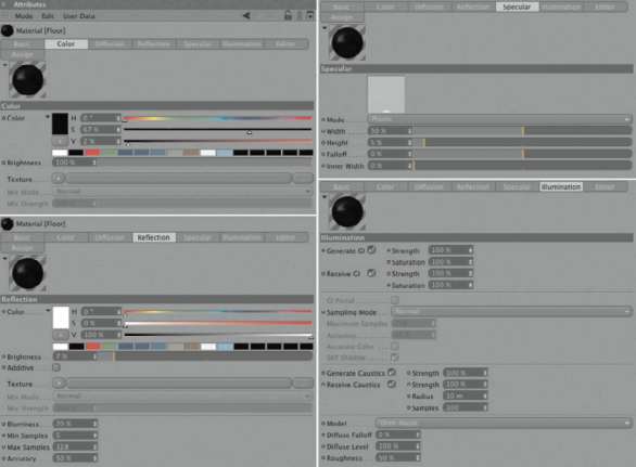
— Figure 1.90: Settings for the floor material.
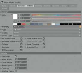
— Figure 1.91: The spotlight of the scene.
I changed the ASPeCt rAtio of the spotlight opening cone, on the detAilS page of the light source dialog, to a value above 1 so the cone has a more oval shape and fits better to the shape of the carabiner. The remaining settings regarding the opening angle of the spotlight can be seen in Figure 1.91. These values are only meant to be a guideline and could be different in your case. They also depend on the distance of your light source from the carabiner.
After my first test rendering the carabiner looked like Figure 1.92. The spotlight generates high-contrast highlighted areas on the carabiner and, at the same time, illuminates the floor only a little because of the strongly reduced INTENSITY. I still miss some liveliness in the chrome material of the carabiner. This can only be changed by having additional objects reflected on the surface.
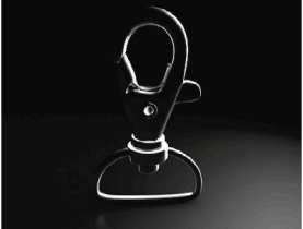
— Figure 1.92: The first test rendering.
Just like in traditional photography, we will use simple white walls. We will create a new material and apply a perfect white color with a brightness of 100%. In order to reduce the brightness of the walls toward the edges and to get a soft reflection, we will use a trick.
Activate the AlPhA channel in the material and load the GRADIENT shader into it. The shader can be found after clicking on the texture triangle at the center of the shader list. The gradient can take on different shapes and directions though its TYPE menu and is quite flexible. I will use the 2d—CirCulAr type and adjust the positions of the two existing color tabs so a gradient is generated, as shown in Figure 1.93. The grayscale gradient should end before it reaches the edge of the square preview area of the shader, so the edges of the shader are perfectly black and the material is therefore invisible in this area.
For the walls we will use two POLYGON objects from the primitives of CINEMA 4D. We could also use the PLANE object but it is already highly subdivided, which would be unnecessary in our scene. Put one of the faces close and in front of the carabiner and angle it slightly. The second face is placed on the left and to the rear left of the carabiner. Figure 1.94 shows the approximate placement of the objects.
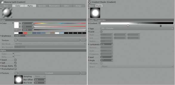
— Figure 1.93: The material of the walls.
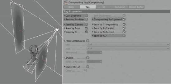
— Figure 1.94: The placement of the walls.
Both polygons then receive the new material by a simple drag and drop. As is common with primitives, the material automatically adjusts to the object and we don’t have to change anything at the TEXTURE TAGS. Both faces, however, should get a COMPOSITING tag, which can be found after a right click in the OBJECT MANAGER in the CINEMA 4D TAGS section.
In these COMPOSITING tags deactivate the SeeN BY CAMerA and SeeN BY Ao. That way, there will not be any shading on the floor and we can place the walls in front of the camera WITHOUT seeing the walls in the final rendering. Also, activate the option for COMPOSITING BACkgrouNd. This suppresses any influence of the light and shading on the surface of the walls. The walls then glow in the color we applied with the material.
If you later want to use light sources that cast shadows, then the two shadow options should be deactivated, as shown in Figure 1.94.
As for the RENDER SettiNgS, I just entered the file format, activated BeSt ANti-AliASiNg and defined a file path. After the rendering in the Picture Viewer, you will have a result similar to the one in Figure 1.95.
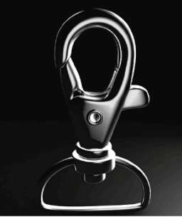
— Figure 1.95: The final image of the carabiner.
Modeling an Antique Vase
In the following chapter we will dive deeper into the possibilities of the render process. We will be illuminating a room, so we need some objects to furnish the room with. Therefore, in this chapter we will next model an antique vase and a small table. In addition to the already known Polygon tools, we will work with the modeling axis and soft selections. At the end of this chapter you will know all the important modeling tools needed for everyday work. The use of the knife, extrude inner, normal extrude, Bridge, and Create Polygon tools should be second nature for you. With these few tools you can model any real or imaginative object.
Modeling the Basic Shape of the Vase
We will start the modeling of the vase with a new Bezier spline, which is created in the front viewport in such a way that it resembles the profile of a bulbous vase, like in Figure 1.96. By subdividing the spline under a lathe NURBS object, the shape of the vase is generated. The vase will be smoothed later by a HYPERNURBS object so we only need the 32 subdivisions along the Lathe NURBS circumference. The interpolation of the spline should be set to uNiForM so the subdivisions are not concentrated only at the curved SEGMENTS. This gives us more control over the shape.
Because the vase should be made of glass, we need a fitting inside wall. Switch to USE POINT TOOL mode, select the spline in the OBJECT MANAGER, and add points to the selected spline with (Ctrl) clicks to generate the inside. If you haven’t created the spline from the base up, you might have to first switch the order of the spline points. To do so, right click in an empty area of the editor and select reverSe SeQueNCe in the context menu. New points are only added at the end of a spline.
Make sure that the first and last points are positioned exactly on the WORLD Y axis, as shown in Figure 1.97. Only that way will the base and bottom be closed automatically by the Lathe NURBS.
Modeling the BULGE
The vase shouldn’t be smooth, but should be encircled by vertical bulges. Therefore convert the Lathe NURBS with the (C) key to a POLYGON object, switch to USE POLYGON tool mode, and select two vertical polygon sections next to each other, as shown in Figure 1.98. This leaves two sections free in between the neighboring polygon strips.
— Figure 1.96: The outer skin of the vase is created with a spline and a Lathe object.
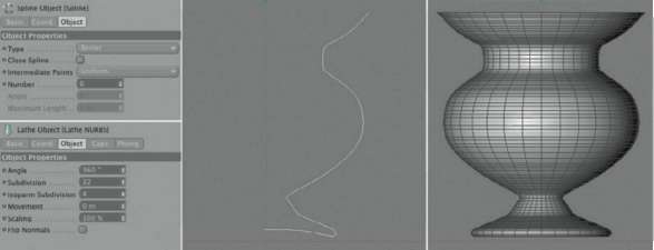
— Figure 1.97: Adding the inside of the vase.
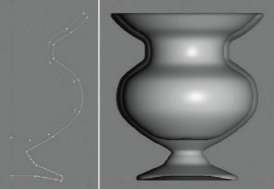
These selected polygons will later be moved outward to create the desired bulges when HYPERNURBS smoothing is applied. To retain the basic shape of the vase between the bulging sections, we use the EXTRUDE INNER tool and shrink these selected areas by a small amount, as can be seen on the far right in Figure 1.98.
WORKING WITH THE MODELING A XIS
Save this polygon selection now by using SELECTION>Set SELECTION. We will access this selection multiple times during the next steps. Since we have to edit every one of the selected sections separately, change to the top view and use any of the selection methods to deselect the other polygon sections. Make sure that the selection of invisible elements is possible. The left image in Figure 1.99 shows a possible result. It doesn’t matter which of the originally selected polygon sections you start with.
Expand the polygon selection at the lower end by two more faces, as shown in the center of Figure 1.99. You can use the live SELECTION while holding the (Shift) key. This time, only visible faces should be selected. Keep that in mind when adjusting the settings in the ATTRIBUTE MANAGER. Then activate the rotAtioN tool and take a look at the MODELING AXIS section in the ATTRIBUTE MANAGER. Here, the axis system of the selected faces can be individually oriented and positioned. This makes it easier to rotate or scale around a certain point.
In the AXIS menu you can determine the position of the modeling axis in 3D space. In the WORLD setting it will jump to the origin of the WORLD coordinate system, while in OBJECT it will jump to the position of the object coordinate system. The setting SELECTEDcenters the modeling axis in the middle of the selected elements of the object.

— Figure 1.98: Freeze selections and extrude them toward the inside.
— Figure 1.99: Moving the modeling axis.
The ORIENTATION menu defines the orientation of the axes of the modeling system. Interesting here is the normal setting, which orients on the surface of the object itself. With the RETAIN CHANGES option the modeling system stays at its original position when the elements are rotated and their position changes. This makes it easier to test different rotations and scales.
ALONG NORMAlS allows the increasing and decreasing of a shape during movement by simultaneously moving and scaling along the individual normal vectors. A similar function is provided by the NORMAIMOVE command in the STRUCTURE menu. The X, Y, and Z sliders in the lower part allow, in some modes, the individual placement of the modeling axis. We will use this in our example in order to position the axis system as exactly as possible at the lower edge of the selected polygons. The AXIS menu is set to SELECTED and the ORIENTATION menu is set to NORMAL. The RETAIN CHANGES option is activated as well.
Now rotate the polygons around the X axis of the modeling axis and outward, as shown on the left in Figure 1.100. Remember the angle that you can see in the COORDINATE MANAGER during the rotation. All remaining polygon sections should be rotated using the same angle. Then select the vertical points located in the center of the rotated polygons and activate the SCAle tool. The modeling axis should be in the center of the selection again. The settings of the modeling axis in the ATTRIBUTE MANAGER should be set to ORIENTATION AXiS, and the X, Y, and Z sliders should be centered. Then scale the points evenly along all axes outward, as shown in the middle and on the right of Figure 1.100.
Restore the original selection of the polygon sections by double clicking on the POLYGON SELECTION tag behind the vase in the OBJECT MANAGER. The process will start all over again. In the top view, deselect all but one selected polygon section, add two additional faces at the lower end, activate the rotAte tool, and move its modeling axis downward. The faces are then rotated by the memorized angle around the X axis. Then scale the center row of points. The left side of Figure 1.101 shows the result after applying all these steps to the remaining polygon sections. The spaces in between are still missing, however. The selected polygons there are also shown in the figure. After the combined EXTRUDE INNER and the saving of this new selection as a tag, these polygons have to be edited using the same process. Figure 1.101 shows the end result.
— Figure 1.100: Rotating polygons and scaling points.
— Figure 1.101: Continuing the modeling of the vase
SHAPING THE INSIDE OF THE VASE
Since the vase will be made of glass and therefore rendered to be transparent, we have to shape the inside as well. The outside bulges should be visible as well, so the wall thickness cannot appear to be too massive. This time we can work much faster, because it will be enough to simply scale the points positioned behind the bulge of the outside wall outward. In the perspective viewport, get close enough to the inside of the vase with the camera to be able to easily select the points. Always select the vertical point rows, which are located in the center of the bulge. Figure 1.102 shows part of the selection on the left. After all these points are selected on the inside, scale this group slightly outward along the X and Z direction. Be sure that the points don’t get too close to the outer hull.
Now you just have to add a hYPerNURBS object and subordinate the vase under it. The result should look similar to the center and right image of Figure 1.102. The basic shape of the vase is now complete.
— Figure 1.102: Shaping the inner walls of the vase.
Creating Ornate Elements and Handles
The vase should also have some ornate elements and some handles. We will start with a collar around the neck of the vase. Add a tube primitive and adjust its radius and HEIGHT to the area between the opening of the vase on top and where the bulges begin at the shoulder of the vase. The left image of
Figure 1.103 gives you a hint. Be sure that there’s no big gap between the vase and the tube. The tube should be close to the vase but should not penetrate the surface.
Then place flat cylinders along the edge of the collar. On the whole they should look like a twisted wire. Since this is a circular placement, the ArrAY object could be used. It can be found in the OBJECT menu under MODELING objects. Subordinate a new CYLINDER primitive under the array in the OBJECT MANAGER. Adjust the size of the cylinder, as well as the position and the radius of the Array objects, so the cylinder copies are created along the upper edge of the collar. The exact placement of the array can be simplified when it is subordinated directly under the tube and the X and Z position coordinates in OBJECT mode are reset to 0 in the COORDINATE MANAGER. The Array object is then automatically placed exactly on the rotation axis of the tube and only its HEIGHT has to be adjusted.
— Figure 1.103: Modeling the upper collar.
As you can see in the lower right part of Figure 1.103, the cylinders should be slightly tilted. This can only be achieved by using a trick, since the ArrAY object orients the subordinated object with its Z axis outward and its Y axis upward. When the desired size and a slight fillet is set for the cylinder in the Array object, you have to convert the cylinder with the (C) key and switch to USE OBJECT AXIS tool mode. Then rotate the local coordinate system of the converted cylinder around its Z axis until the desired tilt is achieved.
Now we just have to determine the right number of copies in the ArrAY object so no gaps can be seen between the tilted cylinders. To do this, create an INSTANCE of the ArrAY object at OBJECTS>MODELING. MOVE it so far downward that the lower edge of the tube is covered with this ornate decoration. Figure 1.104 shows the desired result and the actual hierarchy of the used objects in the OBJECT MANAGER.
THE SOFT SELECTION
So far we have used selections in absolute terms. Either an element is selected or it is not. But CINEMA 4D also knows SoFt SELECTIONS. Here the elements neighboring the selection can still be included in movements, rotations, or scaling. This results in soft transitions, even when the object is already finely subdivided with points.
— Figure 1.104: The finished ornate collar of the vase.
This special evaluation of selections is activated when the MOVE, rotAte, or SCAle tool is selected and the tab for SoFt SELECTION in the ATTRIBUTE MANAGER is used. There you will find an option to activate this effect. With an active Preview option you can get additional feedback about the effect through coloring in the viewports.
Since there are supposed to be two handles on the vase, one to the left and one to the right of the collar, which should extend upward from the vase, I would like to slightly constrict the opening of the vase. Because of the large number of points, the manual moving of points would be very tedious. But with soft selection, this process will be a walk in the park.
Start as usual with the selection of points. We need to select the points on the left and right edge of the vase, as is shown on the left of Figure 1.105. Remember that the vase has an inside and outside surface and that the points have to be selected on both sides. End the selection above the constriction of the neck of the vase, since this area shouldn’t be deformed too much so the collar will still fit.
Then enable the SCAle tool and the SoFt SELECTION in the ATTRIBUTE MANAGER. With an activated Preview you can see the extension and the influence of the soft selection appearing as yellow in the editor. When SurFACe is active, the selection field doesn’t expand in all directions but instead follows the surface. This prevents the accidental selection of the protruding parts of the object that are close to the selected area. This will not happen with our vase, so the option can remain deactivated.
— Figure 1.105: Deforming soft selections.
The RUBBER option results in a sort of dynamic pulling effect of moved elements, as if the surface of the object were made of rubber. Since the impact of this effect is difficult to control, it is used more often for free-form modeling than for objects that need more precise deformations. The RESTRICT option deactivates the soft selection and returns to the normal behavior of selected elements.
With the FALLOFF menu you define the falloff curve for the edge influence of the soft selection. As an alternative, the verteX Map setting can use its own point weighting or the SPliNe setting can use a curve defined by its spline graph. The mode menu determines at which spot the soft selection should be calculated. In the grouP setting, the center of connected selections is used. From this center the soft selection spreads based on the RADIUS setting. With CeNter, the center of all selected elements is used as the center of the soft selection. Depending on the position of the selections, there can be large areal differences. With the All setting, the soft selection starts at the edge of the selected areas and therefore increases the selection by the RADIUS value.
In our case we use the grouP mode and a liNeAr FAlloFF. You have to set the RADIUS value yourself based on the size of your vase. The yellow area of the soft selection shouldn’t reach too far down the neck of the vase. Then scale the selected point groups together as shown in Figure 1.105 on the right. The outside of the vase should slope upward at these places to make space for the handles. When you are happy with the result, deactivate the SoFt SELECTION in the ATTRIBUTE MANAGER with the eNABle option.
THE CURVE OF THE HANDLE
The handles themselves are held by curved supports that start at the collar around the neck of the vase. We will create a spline for the shape as shown in Figure 1.106 and place it so that it nestles up against the surface in the area between the collar and the edge of the vase.
Add a small RECTANGLE spline and subordinate it, together with the other spline, under a new SweeP NURBS. Remember that the profile, the small RECTANGLE spline, has to be the topmost object. With the rotation curve of the SweeP NURBS you can improve the look of the curved support, as shown in Figure 1.106 on the right.

— Figure 1.106: The curve of the handle is created with a spline and a Sweep NURBS.
At the same time, vary the size of the sweep profile with the SCAle curve, as shown in Figure 1.107. A slimmer profile of the collar makes it easier to integrate the curved part.
We can save ourselves some work by using two SYMMETRY objects instead of modeling the other curved supports, which we sorted in a hierarchy, as shown in Figure 1.108. One SYMMETRY object uses the XY and the other one the ZY Mirror PLANE. The order of the SYMMETRY objects doesn’t matter. It is assumed that your handles are placed, in the front viewport, to the left and right of the vase. When your handles are located at another position, you might need to rotate the SYMMETRY object group vertically.
Subordinate the Sweep NURBS object under the lower SYMMETRY object to create the missing curved parts. Figure 1.108 shows the desired result and the hierarchy of the objects.
The Actual Handle
The handle itself is created to be a connection between the pair of curved supports. Add a Cylinder object and position it between one of the two pairs of supports. Because the handle will be smoothed by HYPERNURBS, we do not need that many SEGMENTS. It is enough to use 12 SEGMENTS for the circumference, but since there will be an additional deformation we will need additional HEIGHT SEGMENTS as well. I used 10 SEGMENTS, as you can see in Figure 1.109.
— Figure 1.107: Settings of the Sweep object.
Optimizing Objects
Because we want to work on the polygons of this cylinder, convert it with the (C) key to a POLYGON object. With cylinders and primitives, which have caps, because the conversion doesn’t automatically result in an optimal geometry, we have to pay attention to something else. That means that the separately generated caps of the primitives are not combined with the walls of the object. We have to do that ourselves after the conversion. Select oPtiMiZe from the FUNCTIONS menu. With this function you can determine which elements of the object should be evaluated.
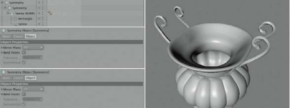
— Figure 1.108: Mirroring the curved support.

— Figure 1.109: A cylinder as handle.
The option POLYGONS and uNUSEd POINTS ensure that the elements that are duplicated or of no use are automatically removed. In our case, the POINTS option is of interest since it works together with a tolerANCe numerical value. All points located within a certain distance of each other below the specified tolerANCe are automatically merged to one point.
This will cause, in our case, the points at the edge of the caps and the points at the edge of the walls to be combined. Generally, you don’t have to change anything in the options of the oPtiMiZe function and can leave them activated at all times. The standard tolerance can also be used as is. Only when you have extremely large or small objects will an adjustment of that value possibly be necessary.
Now you can select every second polygon row of the cylinder and duplicate and shrink this selection with the EXTRUDE INNER function. Then we will use NORMAIMOVE from the StruCture menu and move the new faces slightly toward the center axis of the cylinder. The right side of Figure 1.110 shows the desired result.

— Figure 1.110: Extruding and shrinking polygon strips.
Deforming the Handle
Having been subordinated under a hYPer-NURBS, the handle should display a soft ridge structure like the left image in Figure 1.111. To improve the overall look of the handle we will expand it in the center. Subordinate a new BULGE object under the handle, found in OBJECTS>deForMAtioN. Make sure that it is placed in the center of the cylinder and rotated so the orange handler is located at one of the cylinder caps. The Y size of the deformer should be adjusted so the cylinder is completely enclosed. Using the STRENGTH value, the outward expansion or bulge of the handle can be set, as is shown in Figure 1.111.
Add another deformer, the twiSt object, which is located in the same menu as the BULGE object. This object also needs to be adjusted in HEIGHT and position so that it follows the length of the cylinder and encloses it entirely. With the ANgle value a twist of the cylinder can be calculated to make the ridges appear in a spiral manner. As a result, the twiSt object has to be subordinated under the cylinder as well, as shown in Figure 1.112.

— Figure 1.111: Bending the handle with a BULGE object.

— Figure 1.112: An additional twisting of the handle.
Multiple deformers can affect an object at the same time WITHOUT any problems. Note that they are applied in the order that they are sorted under the object in the OBJECT MANAGER, from the top to the bottom. The results therefore can vary depending on the order.
THE PEDESTAL OF THE VASE
The vase will not just sit on a table or the floor, but will be placed on a pedestal. We will work again in the front viewport and create a linear spline shaping the desired profile of the pedestal. Figure 1.113 shows one possible look on the left.
To have points that are positioned in pairs vertically on top of each other or next to each other, we have to select them and then set the corresponding SiZe value to 0 in the COORDINATE MANAGER. This can also be done in StruCture>Set POINT vAlue. In the menus of the ATTRIBUTE MANAGER the coordinates can then be centered separately with X, Y, or Z, or can be moved to a certain position.
We will round some of the hard edges a bit. Select the points along the spline, as shown in the center of Figure 1.113, and select the CHAMFER command with a right click in the viewport. Either by using the value entry in the ATTRIBUTE MANAGER or by pulling the mouse, add a small rounding before the spline is subordinated under a new LATHE NURBS. This object can be found in objects> NURBS.
If the vase was created at the origin of the WORLD coordinate system, then a correctly oriented pedestal should appear. You can decorate it, like the neck of the vase, with Array objects and you can use the same small cylinders like the ones in the upper Array object. A possible placement of this decoration can be seen in the right image of Figure 1.113. This concludes the modeling of the vase. Of course, you should feel free to add more decorations or DETAILS if you like.
Adding a Simple Table
In order to give the vase some company, we will add a classic Asian-style side table. We won’t get lost in DETAILS since these objects will only be a small part of the scene.
Let’s start with a cube primitive that is adjusted in its size to the dimensions of the vase. My settings can be seen in Figure 1.114. The cube is then converted to a Polygon object so we have access to its polygons. Select the upper face of the cube and use extrude inner from the Structure menu to slightly shrink it. Then change to the Bevel tool that can be found in the same menu. This command is a combination of the extrude inner and extrude commands with the option of adding a rounding as well. We will use this to lower the shrunken top face and to smooth the sides with a radius.

— Figure 1.113: The pedestal of the vase including decorations.
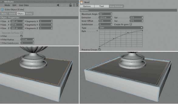
— Figure 1.114: The table top is created from a simple cube.
The eXtruSioN and iNNer oFFSet values are equal to the oFFSet values of the separate eXtrude commands. We will use two identical values, but with different signs, so the face is shrunken and lowered a bit more. In the TYPE menu you can select the different kinds of rounding. With polygons, though, only the liNeAr and USEr types are offered. We will choose USEr so we can create an individual profile for the rounding with the PAth spline in the ATTRIBUTE MANAGER. This spline is shaped by moving the pre-existing points on the curve. We can also add more points to the path by clicking on the curve. Unnecessary points can be removed again by pulling them upward out of the graph.
To actually see the PAth curve we have to increase the number of SuBdiviSioN. My settings and the desired result can be seen in Figure 1.114.
To make the table top appear as if it is put together by individual pieces of wood, we will again use the EXTRUDE INNER command to shrink the surface, as shown on the left side of Figure 1.115. The main surface of the table consists of five polygons that you now select and edit again with EXTRUDE INNER. This time, though, deactivate the PreServe grouPS option in the dialog of the tool. Every face will then be extruded separately. This generates small gaps between the formerly adjacent faces. The right image of Figure 1.115 shows this.
Use the normal eXtrude command with these five single faces to move them slightly upward. This will give the impression of a table being assembled by separate pieces. The rendering in Figure 1.116 depicts this effect. If necessary, correct the distance between the table top and the pedestal of the vase so the vase sits on the table and doesn’t hover over it.

— Figure 1.115: Adding subdivisions.
Using the same principle we will add the lower part of the table. We will model it from a CuBe primitive whose dimensions can be seen in Figure 1.117. Your dimensions, of course, could be completely different. The base should be smaller than the table top and shouldn’t be that tall. After all, the table is just a small side table. After the cube is converted to a POLYGON object, you can build elevated structures like you’ve already done with the table top. The rendering in Figure 1.117 gives some inspiration.
— Figure 1.116: The look of the finished table top.
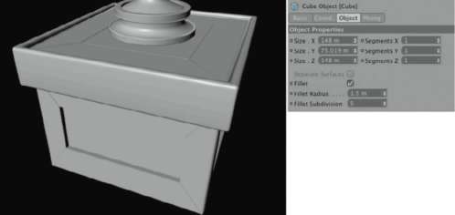
— Figure 1.117: The table base.
The Materials of the Vase
We don’t have fitting materials for the table and the vase yet. We will start with the settings for the vase and create a new material in the MATERIAL MANAGER in FILE>NEW MATERIAL. The goal is a clear glass material that is greenish in its thicker parts. We will start with the COLOR settings and select a dark gray. This color tone is only important later for the reflection and the highlights. The main color is generated by the transparency.
Thus, at the transparency channel we create a 95% transparent material with a refraction index of 1.6. This is equivalent to regular glass. total internal reflection and exit reflections are activated to realistically simulate all physical effects of glass. Finally, we will use a pastel green Absorption color with an Absorption distance fitted to the dimensions of the model. This value shouldn’t be set too small, so the thinner places around the upper opening remain clear and are not tinted. All of my settings are shown in detail in Figure 1.118.
REFLECTION AND GLOSS
The FreSNel part of the TRANSPARENCY channel already causes a reflection at the edges of the vase, but I want to increase it by activating the REFLECTION channel and setting the BrightNeSS to 50%. SPECULAR is adjusted to the desired smooth surface and therefore is very intense and not very wide. Figure 1.119 summarizes these settings.
ILLUMINATION
Because we will work with global illumination again, we shouldn’t forget the settings in the ILLUMINATION section of the material. Generally speaking, very transparent or very reflective materials don’t profit much from global illumination, but this decision is left to us by CINEMA 4D. We therefore decide not to generate or receive global illumination with this material and deactivate the corresponding options. This also speeds up the render time since no additional samples have to be generated to evaluate the objects with this material applied. This can’t be compared with the options in a COMPOSITING tag, though. There, the option SeeN BY gi can be deactivated as well, but it only influences the cast shadow of the object and not its GI illumination. Lastly, I used the oreN-NAYAr shading model so the surface doesn’t look too perfect. This effect will be minimal, though, since the transparent properties are so strong that there is hardly any shading on the surface. Figure 1.120 shows almost all these settings in detail.
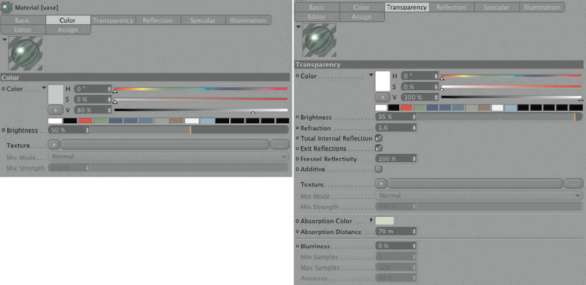
— Figure 1.118: COLOR and transparency of the vase.
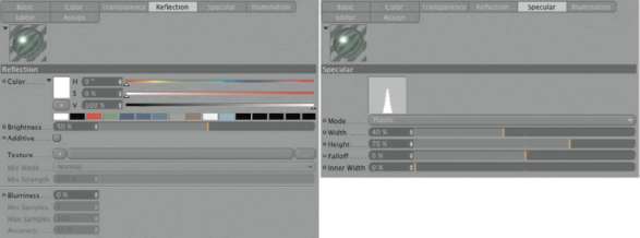
— Figure 1.119: Reflection and gloss.
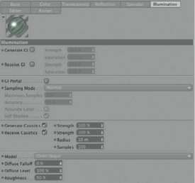
— Figure 1.120: The illumination settings for the vase.
THE BRONZE MATERIAL
The handles and the pedestal of the vase should be made of a bronze material. We will need to create a new material and start again with the COLOR settings. Metals generally have a weak or very dark surface color. This only changes when lacquer or other sorts of coatings are added. Consequently, I used a dark brown tone. A similar but much brighter color is used in the reflection channel. Since the surface reflection is not supposed to be perfect, I set the Blurriness to 20% to calculate a slight blur.
The BUMP channel goes in the same direction by using a Noise shader with a luka pattern. Of course, you could also load an image with a scratch structure if you have one on hand. As you can see in Figure 1.121, I set the bump strength to 10%.
The Highlights of the Material
Colored metals like copper, gold, or bronze can be simulated by using different colors for the reflection and highlights. Therefore, I will set a reddish highlight to contrast with the yellow-brown color of the surface. Otherwise, the highlight is wide and flat to maintain the overall impression. We also keep this in mind in the illumination channel because we use the oreN-NAYAr shading model again. All other settings can be taken from Figure 1.122.
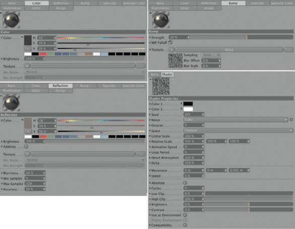
— Figure 1.121: Settings for the metal material of the vase.
The Wood Material of the Side Table
The side table is supposed to have a subtle wood grain and have the expensive look of Asian furniture or piano lacquer. Therefore, we start with a new material and apply a very dark orange color. The reflection is kept moderate yet color neutral at 20%.
The desired wood grain is depicted with the wood shader, which is loaded into the diFFuSioN channel of the material. This shader can be found in the group of the SurFACe shaders. Since the diFFuSioN shader only evaluates the brightness of the loaded shader or images, we reduce the gradient of the wood shader to the colors white and gray, as shown in Figure 1.123. All other options in the upper part of the diFFuSioN channel are deactivated so the shader changes only the color of the material and not the reflection or the highlight. This will emphasize the impression of a perfectly smooth and varnished surface.
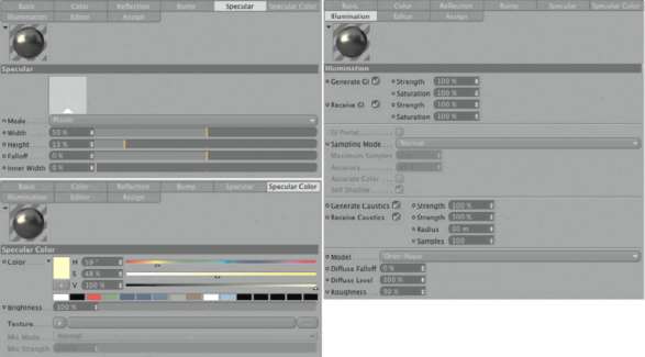
— Figure 1.122: Specular and illumination settings.
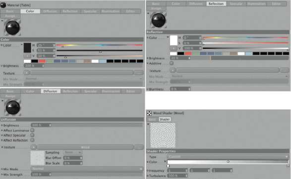
— Figure 1.123: Settings of the wood material.
HIGHLIGHTS AND ILLUMINATION OF THE WOOD
The highlight will remain moderate in its settings since the reflection is supposed to take center stage. We therefore keep the Phong shading in the illumination settings, but reduce it to a diFFuse Falloff of -50%. This reduces the brightness of the shadows quicker than normal along the edge of an illuminated area and simulates a perfectly smooth surface WITHOUT diffuse light scattering. Figure 1.124 shows these settings.
The Environment of the Scene
In order to make a test rendering of our objects at the end of this chapter, we will add a simple environment to the scene. Add a Sky object from the Scene objects in the objects menu. It simulates an infinite sphere that automatically encloses our scene.
We will create a material for this sky sphere and load the gradient into the COLOR channel. In the gradient, select the 2d—v type to generate a vertical gradient and use several colors. I used a gradient that starts with warm yellow colors on the left, continues with white and blue tones, and ends in dark brown colors.
To make it easier to edit and manipulate this gradient, I changed to the main level of the COLOR channel in this material and add another shader, the so-called Filter shader. It doesn’t DELETE the gradient shader but imports it, as shown in Figure 1.125 on the left. For example, this allows us to change the entire saturation or brightness of the gradient WITHOUT having to edit every single one of its colors.
The material is complete and can be applied to the sky by dragging it into the editor or onto the SkY object in the OBJECT MANAGER. Apply the glass and bronze materials in the same manner to the corresponding objects on the vase, and the wood material to the table.
The SkY object has, compared with other objects, some specialties. It not only has an automatically infinite size, but also suppresses all highlights, shading, and shadows. Other characteristics can be controlled with a COMPOSITING tag. For example, you can make the sky invisible for the camera but still use it for transparencies and reflections. This can be useful when you want to use the sky for reflections on an object but want to use another motif as your background image. In our case the sky can remain visible.
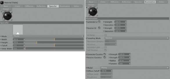
— Figure 1.124: Highlights and illumination of the wood material.
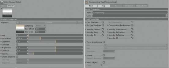
— Figure 1.125: The material and the settings for the environment.
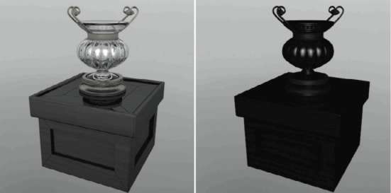
— Figure 1.126: The test rendering of our objects, on the left with the environment and on the right WITHOUT.
Take a look at the test rendering on the left in Figure 1.126. Compare it with the rendering of the same scene on the right, where, in the COMPOSITING tag of the sky, the SeeN BY REFRACTION and SeeN BY REFLECTION were deactivated. The transparent and reflective objects appear almost black because of their low surface brightness. You can see how important such materials are for the environment of your objects.
In the following chapter we will dive deeper into working with the renderer of CINEMA 4D. This will benefit all users of CINEMA 4D, regardless of whether you model your objects yourself or you work primarily with imported objects.
