2 Advanced Workshops
Nothing is more exciting than setting a 3D object into a scene, applying fitting textures, and setting up the lighting. The object itself doesn’t really matter. A 3D character can be just as fascinating as a tastefully lit room. CINEMA 4D has made big improvements, especially in the area of realistic renderings with the Advanced Renderer. Not only did global illumination became easier to use, but it also delivers results of a much higher quality than before. Of course, global illumination doesn’t have to be used at all times. With a little skill and basic knowledge about lighting, attractive images and animations can be rendered WITHOUT having to use the Advanced Renderer. We therefore will literally “shed light” on each of these two methods.
Illuminating a Room
This is the classic example of lighting. We are in a room, and sunlight shines through the window. In the following example we will model, texture, and illuminate such a room using lights as well as the physical sky. A variation of this example will show what changes have to be made in order to illuminate the room with an interior light source.
The Modeling of the Room
What could be easier than to model a room? Well, you will see what problems can emerge even with such a simple task. We will begin, and this may surprise you, by redrawing the footprint of the room with a spline. Depending on the shape of the room you could start with a RECTANGLE spline, convert it with the (C) key, and, if necessary, add more points with (Ctrl) clicks. The footprint could also be imported as an Adobe Illustrator path or the spline could be drawn manually. As you can see in Figure 2.1, I started with a simple rectangular shape, which then is expanded by adding some points to one side. The spline should be positioned in the XZ plane, which means it must be drawn in the top viewport. If your spline was drawn in another viewport, or is oriented differently after the import, you should rotate it before continuing with the next steps.

— Figure 2.1: Modeling the walls of the room.
Because the room will be given windows later on, we have to consider a certain wall thickness. This can automatically be done with the CreAte outliNe function. This function can be found in the StruCture menu under edit SPliNe. The parallel structure should be larger than the original spline so the room volume does not shrink. If you’d like to work more precisely, you could enter the wall thickness for CreAte outliNe as diStANCe in the ATTRIBUTE MANAGER. Otherwise, the CreAte outliNe tool can be used interactively in the editor viewports.
Finally, subordinate the spline under an EXTRUDE NURBS object. Use the MOVEMeNt value in the Y direction to create the desired HEIGHT of the room. Figure 2.1 shows the desired result on the right. The room is already taking shape.
As with all real objects, we have to remember that the edges need to be rounded. So change to the USE POINT TOOL mode and select all points of the spline that are placed inside the room. We will disregard the outer wall for now. Use StruCture>edit SPliNe>CHAMFER to create a small rounding at the selected points, as you can see in the example of one corner in Figure 2.2 on the left. A small radius is enough to remove the unnatural sharpness of the corner.
INTEGRATING THE WINDOWS
The walls are done, and now we will concentrate on the windows. They are also quickly made because of the ability of the BOOLE object to combine objects and subtract them from each other. We will use it to subtract two cubes and one cylinder from the walls. The center image of Figure 2.2 shows the highlighted positions of the two cubes and the cylinder. It is important that the objects go all the way through the walls and that the cylinder contain a sufficient number of circumferential SEGMENTS. Otherwise, the circular opening will show some linear SEGMENTS, and the correction of such a mistake can be quite time consuming. Here I used 72 SEGMENTS for the circumference of the cylinder. I also added a small rounding to the cubes so the window openings will have soft edges.
Then add a BOOLE object from ModeliNg in the OBJECT menu and activate the options CREATE SINGLE OBJECT and HIDE NEW EDGES. HIGH QUALITY and BOOLEAN TYPE A SUBTRACT B should be activated by default. That way, after the conversion of the BOOLE object, we will get an optimized object containing n-gons, which will make it easier to round the window opening. The hierarchy of the objects can be seen in Figure 2.3. The Extrude NURBS comes first, followed by one of the window objects that was combined into a group. This setting makes it possible to cut the three holes by using just one BOOLE object.
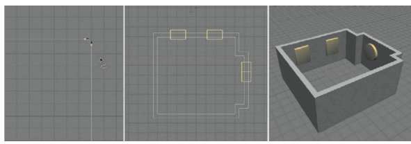
— Figure 2.2: Rounding the edges and placing the windows.
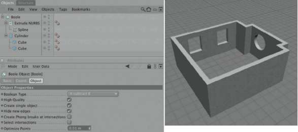
— Figure 2.3: Subtracting the window objects from the room.
There is still time to move the windows or to change their size. When you are happy with their placement, convert the BOOLE object. Use the MAKE EDITABLE command in the FUNCTIONS menu or the familiar (C) key.
Smoothing the Openings
To be able to add a ceiling and a floor later, we should select and DELETE the former caps of the Extrude NURBS. These faces can be seen highlighted in the left image of Figure 2.4. These faces were only necessary so that the BOOLE object could function, since it only works reliably with closed objects. Then use the RING SELECTION in the SELECTION menu to select the three window openings. Hold down the (Shift) key to select all three openings one after the other. These selections can be seen in the center and the right image of Figure 2.4.
From the StruCture menu select the Bevel command. You will use it to generate a small rounding along the openings. A small value of 1 for eXtruSioN and iNNer oFFSet should be enough, but it depends on the scale of your room and windows. It is important that the MAXiMuM ANgle is set to a value above 90°. Otherwise, the sides of the rectangular windows could be rounded independent of each other. Thus the PreServe grouPS option has to be active as well. The actual rounding is determined by the SuBdiviSioN value and the TYPE. In the TYPE setting liNeAr you can create the path, defining the profile of the rounding. Figure 2.5 shows an example. As long as the tool is active, the values and the course of the path can be changed. Thus you can take your time and experiment until you find the desired rounding.

— Figure 2.4: Converting and modifying the BOOLE object.
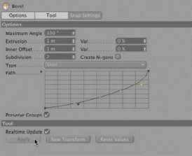
— Figure 2.5: Rounding the window openings.
Select only the polygon loop in the middle of the two rectangular openings with the RING SELECTION. The faces of the round opening should be deactivated completely. We will do something else with that opening. First, slightly shrink the selected faces of the rectangular window openings with the eXtrude iNNer function, as shown in Figure 2.6. Here, too, it is important to preserve the groups and to use a MAXiMuM ANgle above 90°. Then use the MOVE tool to reposition the shrunken faces, as far as the surrounding geometry allows, toward the outside of the wall. The arrow on the right side of Figure 2.6 indicates the direction and shows the end position of the polygons.
These faces are supposed to close the gap between the window frames and the window opening. So we will use the eXtrude command on these faces and reduce the size of the window openings. Here the requirements are again the same regarding the maximum angle and the preservation of the groups, as shown in Figure 2.7. You can see the desired result in the middle image. Then change to USE edge tool mode and use the looP SELECTION in the SELECTION menu to select the edges at the base of the extruded faces, as shown in Figure 2.7.
Here the Bevel tool does a good job rounding the hard edges. This time it is easier, though, since edges, contrary to polygons, can have predefined rounding types applied to them. In most cases the convex type will be used. As can be seen in Figure 2.8, it is enough to use a small rounding to soften the hard edge. By the way, this is only necessary at the edge of the window opening inside the room. The corresponding edge on the outside can remain as is.

— Figure 2.6: Preparing the base for the window frame.
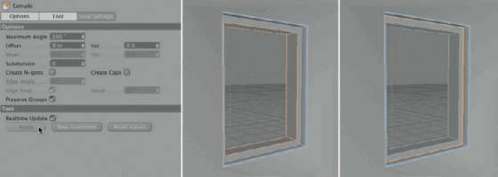
— Figure 2.7: Finishing the base.
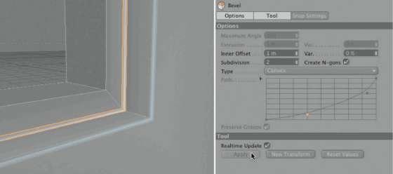
— Figure 2.8: Rounding the edges.
Framing the Round Window
Let’s shift our attention to the round window opening on the other wall. I decided to not use it as a window but as a decorative element instead. I would like it to have a decorative grid with a reflective surface behind it. The mount of the grid is simulated with a tuBe object that can be found in OBJECTS>PriMitive. First, set the direction of the tube so that it aligns with the round opening and then use the handler to adjust the size of the tube to the diameter of the opening. The tube may sink into the wall, as shown highlighted in Figure 2.9. There you can also see, in my settings of the tuBe object, that I added a rounding with a number of circumferential SEGMENTS corresponding to the number of the opening SEGMENTS.
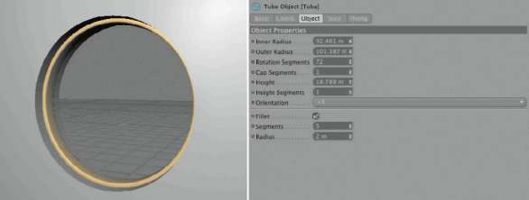
— Figure 2.9: Inserting a tube into the window opening.
CORRECTING THE SHADING IRREGULARITIES
Upon closer examination of the room you might notice the distinctively different levels of shading on the walls, as shown in Figure 2.10 on the top left. This is always the case when small faces border large ones and the two faces are oriented in different directions. In our case, the walls consist of very large n-gons. The window openings, on the other hand, are surrounded by many small polygons that shape the rounding of the edges.
Sometimes this problem can be solved by lowering the angle in the PhoNg tag of the object. In our case, though, this would make the roundings of the openings and the room corners look faceted. In these cases it helps to add faces at the border of the large polygons and to apply the same tilt to them as on the large faces. Select the two faces of the two walls with the window openings and select the eXtrude iNNer command from the StruCture menu. Use a small oFFSet value of maybe 1 or 2 and check what happens to the shading when it is applied. As you can see in the bottom row of Figure 2.10, the problem disappears instantly WITHOUT us having to adjust the phong angle at all.
MODELING THE CEILING
Let us now look at the ceiling of the room. Here, too, there are some problems waiting to be solved. At first glance everything looks easy. We DELETEd the caps of the converted room so that the open edges, on the top and bottom of the room, can be used for modeling the ceiling and, later, the floor. Therefore, use the CloSe POLYGON hole tool in the StruCture menu, as shown in Figure 2.11 and single click on the upper open edge of the inside wall.
The next step is to round the transition between the wall and the ceiling with a fillet or rounding. Let’s try to use the eXtrude iNNer tool and see what happens to the ceiling. Select the recently created surface of the ceiling and shrink it with the eXtrude iNNer tool in the StruCture MeNu. Room corners protruding into the room don’t cause any problems, as you can see in the left image of Figure 2.12, but what happens to the other corners?
As shown by the highlights on the right side of Figure 2.12, the new polygon edges part from the original edges and the result is intersecting faces. The problem is increased by the large number of points generated by the rounding in the room corners. A manual correction would take too much time. Therefore, undo the rounding with the uNdo function in the edit menu of CINEMA 4D. We have to find a different solution.
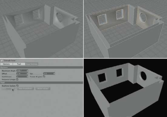
— Figure 2.10: Correct the shading with extrusions.
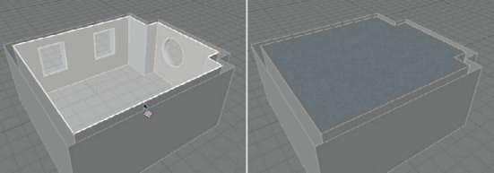
— Figure 2.11: Closing the open edge of the inner wall.
Shaping the Transition to the Walls
In our second try, we will use the extrude inner command again, but this time with an offset of 0. This generates new faces that remain in the same position as the original ones. To shrink the new faces we will use the NorMAl MOVE command in the StruCture menu. This takes into account the direction of the normal vector on the faces and therefore can help us avoid intersecting polygons during shrinking. Use the SCAle percentage value in the ATTRIBUTE MANAGER to shrink the ceiling. Since the tool works very well I decided to extend the small rounding and create a wide decorative bevel. A number of images in Figure 2.13 show my settings in the mentioned tools. Remember that your values could be different, depending on the shape and size of your room.
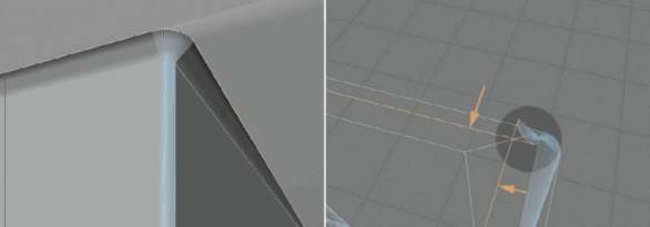
— Figure 2.12: Trying to round the edge between ceiling and wall.
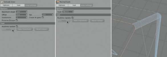
— Figure 2.13: Scaling along the normal direction.
A view from above the shrunken ceiling reveals some irregularities regarding the distance to the walls, but this can be quickly corrected. Figure 2.14 shows the different distances to the walls in the example of a room corner. The selected points can easily be moved to an even distance, as can be seen in the figure. It is enough to just eyeball it.
Perhaps it confuses you that I mentioned a bevel several times, because the ceiling is actually still in the same plane as the DELETEd upper cap of the walls. This will now be changed by pulling up the shrunken ceiling polygon. Figure 2.15 indicates this movement with an arrow. At the edges of the moved polygons you can see where the bevel between ceiling and walls has been created.
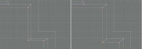
— Figure 2.14: Corrections for an evenly wide fillet.
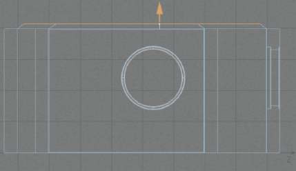
— Figure 2.15: Lifting the ceiling.
Viewed from the inside of the room, as can be seen in Figure 2.16 in the upper left corner, the bevel doesn’t look that good. There is no sharply defined edge below and above the bevel. As a result we need to activate the kNiFe tool in PLANE or looP mode in the StruCture menu and add two more cuts within the tilted faces of the bevel. One cut runs slightly above the lower edge of the bevel, and a second runs close to the upper edge near the shrunken ceiling. Then select the actual ceiling polygon and use the eXtrude iNNer tool with a very small or no oFFSet at all. This step and the result are documented in Figure 2.16. As you can see in the lower right view, the shading problems are solved and the bevel is clearly separated from the ceiling and wall.
MODELING THE WINDOW FRAME
The next steps will focus on the creation of a window frame. If you have used two identically sized cubes for the openings, then you have to model only one frame. The second frame can be added and moved to the other opening.
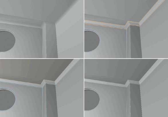
— Figure 2.16: Correcting the phong angle with new subdivisions.
We start, as we have done so often before, with a CuBe primitive and adjust its size to the rectangular window openings. The portion of the wall protruding into the opening can be partly intersected by the cube. Figure 2.17 shows how such a scaled and positioned cube looks in the opening of the wall. We don’t have to add roundings or SEGMENTS to the cube for now.
To get from a cube to a frame we have to open the cube in the center. After the cube is fitted to the opening, it is converted with the (C) key. Change to USE POLYGON tool mode, select the large front and back side of the cube, and use the eXtrude iNNer tool to define the WIDTH of the frame up to the glass part. Figure 2.18 shows this in the left and center images. The connection of these two faces will create the opening where later the glass will be placed. Use the Bridge tool in the StruCture menu and pull a connection line between the two upper or two lower corner points of the selected polygons. When you release the mouse button the two faces are connected, creating an opening, as can be seen in Figure 2.18.
Modeling the Groove for the Glass Pane
The glass pane doesn’t just float inside the frame but is held with an additional groove that we will now model. Start by shrinking the four inside faces of the frame opening with eXtrude iNNer. Again, it is important to preserve the groups and set a maximum angle above 90° to prevent four separate faces from being created. A possible result is shown on the upper left of Figure 2.19.
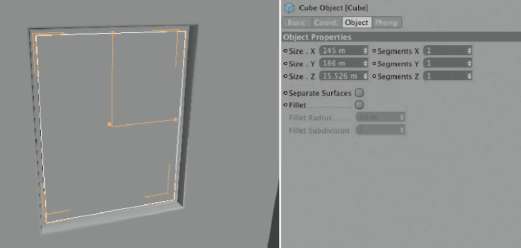
— Figure 2.17: Fitting a cube primitive.
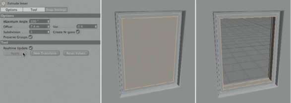
— Figure 2.18: Opening the frame in the middle.
In USE edge tool mode, use the looP SELECTION to select the parallel rectangles that were created by the eXtrude iNNer tool. Hold down the (Shift) key to make multiple selections. The two selected edge loops can be seen in the upper right image of Figure 2.19. These edges will now be duplicated with the Bevel command in the StruCture menu. This command can be used not only for roundings but also to generate parallel edges. The only condition is that the selected edges can’t be located at the angled edge of the object and must be in one plane.
Use the liNeAr type for roundings WITHOUT any additional subdivisions. The option for n-gons can be activated but it won’t make any difference here. The tool settings and the desired result can be seen in the lower row of Figure 2.19.
The additional subdivisions allow us to select two polygon loops with a gap between them. The best tool to use is the Ring Selection in Use Polygon Tool mode, as shown in Figure 2.20 on the left. The actual groove for the glass pane is created with an extrusion of these faces, as shown on the right of the figure. Here, too, remember the maximum angle and the preserved groups.
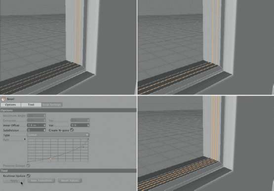
— Figure 2.19: Adding more subdivisions.
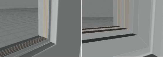
— Figure 2.20: Extruding the groove for the glass pane.
Into this groove place a properly scaled new cube. The thickness of this cube has to be oriented to the WIDTH of the groove. Figure 2.21 shows the cube on the left, still hovering in front of the frame. In the OBJECT MANAGER, subordinate the glass pane under the window frame.
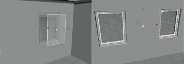
— Figure 2.21: Fitting the glass pane and duplicating the window.
If both openings have the same size, you can add the missing second window by creating a simple copy. Select the window frame with the subordinated glass cube and choose the iNStANCe object in OBJECTS>ModeliNg> iNStANCe. The new iNStANCe object automatically takes on the selected object as a reference and can be moved to the second window opening. This could look like Figure 2.21.
MODELING THE BASEBOARD
Now we come to the lower part of the room. There, the baseboards and, of course, the floor are still missing. In order to have the most freedom regarding the size and shape of the baseboard, we will start with a looP SELECTION in USE edge tool mode. We are interested in the edge loop at the lower end of the walls, as shown in Figure 2.22. When you activate the SeleCt BouNdArY looP option in the looP SELECTION settings, you can be sure that the correct edge loop will be selected.
With StruCture>edit SPliNe>edge to SPliNe, this selection can be converted to a normal spline object. This spline, together with a RECTANGLE spline, can then be subordinated under a SweeP NURBS, as shown in Figure 2.23.
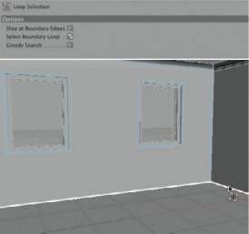
— Figure 2.22: Creating a path for the baseboard.
Be sure that the profile, in our case the rectangle spline, is located in the XY plane so it can be used properly by the Sweep NURBS. In addition, the rectangle spline has to be positioned uppermost in the Sweep NURBS group, followed by the path we extracted from the walls. After that, two more steps are necessary so that the baseboard is located at the right place. First, the local axis system of the rectangle spline should be moved along the X axis to the right. This will make the whole baseboard move out in front of the walls and not be halfway immersed into the walls. This manipulation, however, requires that the rectangle spline first be converted. Therefore, you should add a small rounding to this spline and then convert it with the (C) key. Afterward, switch to USE OBJECT AXiS tool mode to move the axis system.

— Figure 2.23: Creating the baseboard with a Sweep NURBS.
The second step regards the position of the extracted path spline. It has to be moved so far upward that the baseboard is level with the bottom of the wall. The amount of this move depends on the HEIGHT of the baseboard. The image series in Figure 2.23 summarizes the steps. From left to right you can see first my settings for the profile spline and then its conversion and the movement of its axis system. In the center, the movement of the path spline is indicated by an arrow, and on the right is the possible result.
CREATING A DOUBLE-WALLED CEILING
Less because of aesthetics than for practical reasons, we will get back to the ceiling, but this time from the outside. Maybe you will later discover that you need an opening in the ceiling. In that case it would be better for the ceiling to have some thickness, making it easier to use the BOOLE object. In USE edge tool mode, select the open upper edge of the outer wall with the looP SELECTION and move these edges so far up that they will surpass the edges of the inner ceiling. The upper face of the ceiling can then be closed with the CloSe POLYGON function in the StruCture menu, as shown in Figure 2.24.
A nice side effect of this step is that lower settings in global illumination can be used during rendering WITHOUT having the light penetrate the walls from outside. The doubled polygons of the ceiling and outer walls filter out this irregularity.
CREATING THE FLOOR
The floor is created using the same principle, only we don’t have to move any edges. We simply use the CloSe POLYGON function with the open edge loop of the outer wall, as shown on the right in Figure 2.25. The generated face then appears automatically under the baseboard on the inside. Only the orientation of this polygon has to be corrected, as can be seen in the middle of Figure 2.25. The face appears bluish when selected, which means it shows its rear side. This could cause problems later, for example, when baking textures. As a result, we should fix that problem right away by inverting the orientation of the selected face with FUNCTIONS>reverSe NorMAlS. As shown on the right in Figure 2.25, the polygon now depicts yellowish shading.
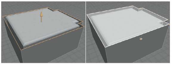
— Figure 2.24: Closing the outer room corner.

— Figure 2.25: Closing the floor.
FINE-TUNING THE ROOM MODEL
In this section we will take care of the fine points that make the room look more detailed and comfortable. We will start with the bevel at the ceiling, which, for my taste, is still too simple. A crown molding strip should improve the look of the transition between the wall and the ceiling. The modeling of such an element is not easy, since we have to consider a lot of corners with rounded edges. We previously discovered, when modeling the bevel and the ceiling, what difficulties can occur. Therefore, I want to use another method that is easier to handle.
Editing the Bevel at the Ceiling
We first need two splines between which the crown molding strips will be stretched. Use the looP SELECTION in USE edge tool mode and select the edge loop that borders the bottom of the bevel. Make sure that in the settings for the looP SELECTION the SeleCt BouNdArY looP option, which was used in previous steps, is deactivated. Otherwise, edges on the inside of objects cannot be selected.
This selection is then converted to a spline object with StruCture>edit SPliNe>edge to SPliNe. Apply the same steps to the bevel edge loop that borders the ceiling. Figure 2.26 shows both selections. The two extracted splines are now used with a loFt NURBS to create a polygon skin between them. These splines can be found subordinated under the object from which they were generated. In our case the splines are subordinated under the room object in the OBJECT MANAGER. As with all NURBS objects that work with splines, the order and direction of the points of the two splines used are very important. When extracting several splines from edge selections, it is likely that the starting points of the generated splines are not aligned. This should be corrected manually so the loFt NURBS object can create clean results.
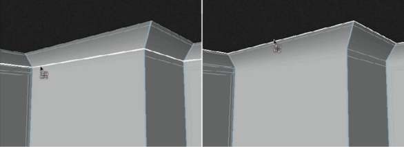
— Figure 2.26: Converting edge selections into paths.
In USE POINT TOOL mode select a point of the lower spline and choose StruCture>edit SPliNe>SET FIRST POINT. Repeat this with the second spline using the selected corresponding point. If the splines are running in the opposite direction from each other—you can identify this at the gradient of the splines— correct that as well at one of the splines in the StruCture menu with edit SPliNe>reverSe SeQueNCe. Then subordinate the splines under the new loFt NURBS object. The Loft NURBS has the ability to set its own points along the splines and connect them. The intermediate points of the used splines don’t affect this type of NURBS. Therefore, we have to significantly increase the subdivision in the horizontal U direction so the loft shape adjusts enough to the shape of the walls and corners. Too many subdivisions wouldn’t be that bad, but it would use more memory WITHOUT improving the quality of the result. I also set the vertical V subdivisions quite high, even though it would theoretically be enough to use just one subdivision. After all, we just have a straight connection between two spline curves. My settings and the result can be seen in Figure 2.27. The shape of the Loft NURBS is highlighted and currently looks like the bevel we modeled at the ceiling.
Deforming the Object with Displacement
The reason for the fine subdivisions is that I would like to deform the object in the next step with displacement. Therefore, I need a lot of points in order to generate a soft deformation with many DETAILS. Create a new material for the loft NURBS in the MATERIAL MANAGER in FILE>NEW MATERIAL and load the gradient shader in the COLOR channel. This shader works well with the Loft NURBS since the Loft NURBS automatically generates UV coordinates and causes the gradient to adjust perfectly to the shape of the modeled bevel.
Like in Figure 2.28, select the gradient in the vertical direction, the 2d - v type, and create a grayscale gradient. It should end on the left and right in a very dark color. The displacement will apply the most deformation to the brightest areas in the gradient. Dark or black areas remain unchanged. This is important for the edges of the gradient because it makes sure that our deformed Loft object remains close to the walls and ceiling after the deformation.
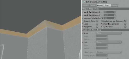
— Figure 2.27: The Loft NURBS above the ceiling bevel.
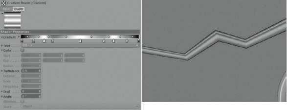
— Figure 2.28: A gradient at the Loft NURBS object.
As soon as the material is pulled onto the Loft object, you can take a look at the coloring in the editor and change the gradient until you like the WIDTH and position of the bands of color. Additional color tabs can be created with a single click under the gradient. COLORs that aren’t needed anymore can be DELETEd by pulling the tab upward, out of the gradient again.
Now use the CoPY ChANNel command within the shader menu in the TEXTURE area of the COLOR channel to copy the gradient. Then activate the diSPlACeMeNt channel and use the PASt ChANNel command in the TEXTURE area to paste the gradient. The gradient in the COLOR channel can then be DELETEd by using Clear in the Shader menu.
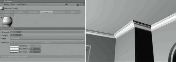
— Figure 2.29: The displacement deformation.
My settings for the displacement channel are in Figure 2.29. You only need to select the INTENSITY type, so black is used as the starting color in order to not trigger a deformation. The value for the HEIGHT defines the maximum deformation of the object. The use of either a positive or negative sign depends on the orientation of the faces on the object. This can only be clarified with a test rendering of the object, as can be seen in Figure 2.29 on the right. If the deformation is going into the wall, then the sign for the HEIGHT has to be reversed.
This is a very elegant tool to use to create wave-shaped profiles for the crown molding. The render time for the displacement remains reasonable since we work with real points and didn’t use Sub-Polygon displacement.
The Window Handle
Another object we could add to the window frame is the window handle. We will add a simple object to portray the handle by starting with a new Cube primitive with two SEGMENTS in the Y direction. The standard size of 200 units in all directions can remain the same. Convert the cube with the (C) key to a Polygon object and select the Subdivide value from the Functions menu. This adds points to the object by subdividing every edge with the defined SuBdivide value. We can also activate the hYPerNURBS SuBdivide option. After activating this function the object will look like it was subdivided and rounded by a HYPERNURBS object.
My settings can be seen in Figure 2.30. I used a simple subdivision of the cube, but with HYPERNURBS smoothing. Now we have enough new faces on the object to extrude two neighboring polygons from the upper edge so a handle is created, like the one on the right in Figure 2.30. Since the eXtrude tool uses the normals of the polygons as the direction of movement, you should use only a small oFFSet value and do the actual movement manually with the MOVE tool. When the desired handle length is reached, shrink the two still-selected polygons at the end of the handle with the eXtrude iNNer function. This will result in a sharper edge later when the HYPERNURBS smoothing is applied. The right side of Figure 2.30 shows this step as well.
Subdivide the handle under a HYPERNURBS object to get a better sense of the smoothed shape. If necessary add one or two cuts using the kNiFe tool in looP mode, vertical to the length of the handle, and use these additional subdivisions to give the handle a slight bend. Figure 2.31 shows an example in the side view. There you can also see that I have moved the lower faces at the base of the handle upward, creating a small plane. We will add a small plate to this spot later.
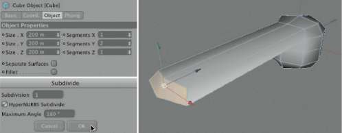
— Figure 2.30: Extruding the handle from the rounded cube.

— Figure 2.31: Shaping the handle.
To add more definition to the top of the handle, select the faces highlighted in Figure 2.31 and shrink them slightly with the eXtrude iNNer command. The newly created subdivisions allow the handle to appear less rounded.
Once you are happy with the handle, you will need to add a plate that will be used to connect the handle to the window frame. Start by adding a new cube primitive and resizing it so the cube is in proportion to the handle. Three SEGMENTS in both the Y and Z directions ensure that the cube will be rounded via HYPERNURBS but not completely lose its shape. Figure 2.32 shows my settings. You should base the size of the cube on the dimensions of your handle, though.
Then group the cube with the handle so both objects are smoothed by the Hyper-NURBS object and adjust their positions, as shown in Figure 2.32. Now it is time to adjust the handle unit to the window frame, as highlighted on the right in Figure 2.32. Adjust the proportions of the handle by scaling the complete handle hierarchy to the frame. Also control the position and level of the handle with the frame so there is no gap between the plate and the frame, and put the Hyper-NURBS with the handle into the window frame group. If you created the second window frame as an Instance, then the handle will appear there as well. Otherwise, you have to create a copy or an Instance of the handle itself and move it manually to the second window frame.
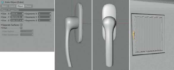
— Figure 2.32: A simple plate for attaching the handle to the frame.
Modeling the Decorative Grid
I previously mentioned that the circular opening will not be a window but instead a decorative part of the room. Therefore, we will now model the round grid with decorative elements. Because of the tubular insert, we already know the approximate diameter of the opening. We will use this measurement as the radius for a new ArC object found in the SPliNe PriMitive menu in the OBJECTS menu of CINEMA 4D. This object represents a sector of a circle. Choose the XY PLANE as the set plane in the dialog of the ArC object, which is the front view, and limit the range of the arc to be between 0° and 90°, as shown in Figure 2.33. After rotating the arc by –45° in the B rotAtioN value field of the COORDINATE MANAGER, the arc should be standing on its tip. This represents the space that we will now fill with decorative spline elements. Later we can fill the circular area with mirrored copies of this arc area.
On the right side of Figure 2.33 you can see how I worked. First, I placed a slim cube along the WORLD Y axis. It will later be the support beam for the elements of the decorative grid. It also helps to fit the spline curves into place. You have free range to create your own spline curves. As you can see in the figure, I created three spline curves in the front view that are oriented to the arc as well as the cube. These splines are subordinated under SweeP NURBS objects to depict bent metal bars. You can also use the spline curves for scaling and rotation in the SweeP NURBS objects to shape the bars to your liking. Just make sure that there are enough interpolation points set to create smooth looking bars.
Subordinate the three Sweep NURBS objects under a new Null object—it can be found in the OBJECTS menu of CINEMA 4D— and rotate them by 45° around the B axis, so the decorative elements are located to the right of the WORLD X axis. If you want, you can add small CuBe primitives to simulate clips that hold the elements together. Subordinate them under the Null object. This Null object is then subordinated under a SYMMETRY object that can be found in OBJECTS>ModeliNg. Set the Mirror PLANE of the SYMMETRY object to XZ. The result could look similar to the left image of Figure 2.34.
Create another SYMMETRY object and set the Mirror PLANE to ZY. Subordinate the other symmetry object under the new one in the OBJECT MANAGER. The result is shown in the center of Figure 2.34. Select the last created SYMMETRY object and choose the iNStANCe object in the OBJECTS menu under ModeliNg. This represents a copy of the symmetry group and can now be rotated by 90° around the B angle in the CoordiNAte ManAger to complete the circle. The result is shown on the right of Figure 2.34. I also extended the vertical cube and rotated a copy horizontally to get a supporting cross structure for the grid.
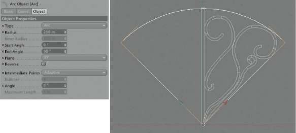
— Figure 2.33: One element of the grid.
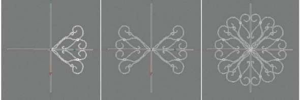
— Figure 2.34: Multiplying the decorative elements.
If you want, you can add some more small cubes to simulate the connectors that hold all the elements together. The test rendering on the right in Figure 2.35 shows the entire grid, including the added cube clips. In the center image is the hierarchical structure of the grid. As you can see, I subordinated all the elements under a Null object to be able to scale and move the Instance, the symmetry group, and the separate cube clips at the same time. Fit the grid into the round window so it is anchored to the tube. The right image in Figure 2.35 shows this result. Looking out from the inside, place a PLANE object or, even better, a simple POLYGON object behind the grid. It is supposed to depict a mirror that closes the opening in the wall.
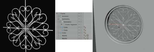
— Figure 2.35: The finished decorative grid.
The modeling of new objects is now complete. We previously modeled and textured a vase, including a side table, in the first chapter. Load those objects into the scene by using FILE>Merge. Place them in an appropriate place and adjust their size to be proportional to the room.
The Materials of the Room
I want to keep the materials of the room simple. The room is supposed to generate a mood by way of its illumination. We will discover later, during the process of lighting with global illumination, what problems can occur.
THE WALL MATERIAL
We will start with the settings for the wall and create a new material. I used a very subtle NoiSe shader with two almost identical colors. This slightly structured look of wallpaper is supported by the oreN-NAYAr shading model in the ILLUMINATION settings of the material. The settings of the material can be seen in Figure 2.36. The material can then simply be dropped onto the room object. Since the walls were for the most part generated by an Extrude NURBS object, the existing UV coordinates are enough to create a proper projection of the material.
THE BASEBOARD AND THE CROWN MOLDING
We will use an understated material for the baseboard and the crown molding. I used a slightly warm color and the oreN-NAYAr as shading model, as shown in Figure 2.37. Remember that we already created a material for the crown molding and just have to adjust the color and the shading model. The material of the baseboard can again be applied by a simple drag and drop. Even the absence of UV coordinates isn’t a problem, since the material doesn’t contain any images or structures.
THE CEILING MATERIAL
The ceiling is supposed to be perfectly white and with a rough composition. Therefore, we use the NoiSe shader with a SeMA pattern in the BUMP channel of a new material. Set the STRENGTH of the bump to a low value so the effect doesn’t appear to be too strong. Here, too, the oreN-NAYAr fits perfectly to the desired surface type. All settings can be seen in Figure 2.38.
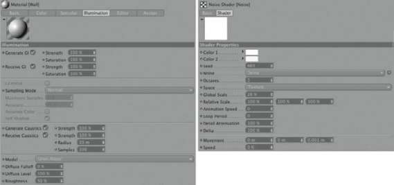
— Figure 2.36: The wall material.
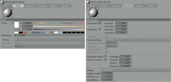
— Figure 2.37: The material for the baseboard.
To be able to apply this material, you have to first make a polygon selection of the ceiling polygon and save it in a SELECTION tag. Use the Set SELECTION command in the SELECTION menu of CINEMA 4D. Give the new POLYGON SELECTION tag a meaningful name in the ATTRIBUTE MANAGER, for instance, ceiling, and then pull the ceiling material onto the room geometry. In the new TEXTURE tag, add the name of the previously saved polygon selection to the SELECTION field so the material is seen exclusively on these polygons. Also make sure that in the OBJECT MANAGER, the TEXTURE tag of the ceiling material is placed to the right of the TEXTURE tag of the wall material. Then the ceiling material won’t be covered by the wall material. Set the PROJECTION of the ceiling material to CuBiC. uvw MAPPiNg cannot be used here since the ceiling was created manually with an n-gon. Therefore, no reliable UV coordinates exist.
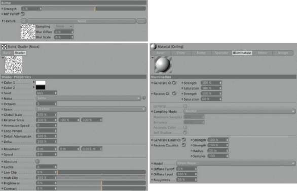
— Figure 2.38: The material for the ceiling.
THE WINDOW GLASS
Of course, the window pane receives a mostly transparent material, as shown in Figure 2.39. I prefer to use a material with a high degree of transparency, but still under 100% since an absolutely transparent material doesn’t exist. In addition, the reflections will look better. For the REFRACTION index I used the usual 1.5 while leaving the FreSNel reFleCtivitY at 100%. The latter increases the reflective capabilities when looking at the window pane from an angle. The options for totAl iNterNAl REFLECTION and EXIT REFLECTIONS can remain deactivated since only two parallel polygons are positioned across from each other. These effects would hardly make a difference.
I also activated the REFLECTION channel to be able to control separately the reflective properties from the fresnel effect. The BrightNeSS value is set pretty high at 70%, but is balanced automatically by the high transparency of the window pane.
Now we will get to the ILLUMINATION settings of the glass material. We will keep the PhoNg shading model, which is appropriate for smooth surfaces, but we will deactivate all options in the upper part of the dialog that are associated with generating and receiving global illumination. The more reflective and transparent a material is, the less it benefits from global illumination. Thus I recommend that you deactivate these options to save some render time later. Since sunlight is supposed to enter the room through the window, we can support the global illumination by activating the gi PortAl option. This option allows rays, which are used to calculate the global illumination, to concentrate on the objects that use this material.
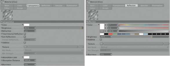
— Figure 2.39: The material for the window glass.
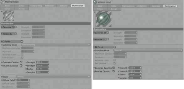
— Figure 2.40: Illumination settings of the glass materials in the scene.
Apply the same principle to the glass material used for the vase, keeping the gi PortAl option deactivated. We do this because there is no light source in or behind the vase and a concentration of rays on this object wouldn’t make sense. Figure 2.40 shows the options for the two glass materials of the scene in detail.
THE MIRROR MATERIAL
As previously mentioned, the calculation of global illumination for very reflective objects doesn’t make sense, since the rays used for the calculation simply bounce off the object and hit other objects in the scene. This is balanced, of course, by a decreasing amount of reflection on the object. Objects with 50% or 60% reflection allow you to decide for yourself whether the surface color should also be influenced by the global illumination or not. With chrome or mirrored surfaces at almost 100% reflection, we don’t have to worry about that. As you can see in Figure 2.41 I used a warm white color, with 95% BrightNeSS in the REFLECTION channel of the material, for the mirror behind the grid. The GI options in the ILLUMINATION channel all remain deactivated.
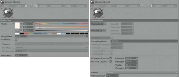
— Figure 2.41: The material for the mirror.
All remaining materials not yet mentioned are more subtle. You can apply a simple black material, WITHOUT reflection, to the Sweep NURBS object of the decorative grid. The clips on the grid would look good with a contrasting color. Therefore, I re-used the bronze material of the vase. For the window frame and handles, it is enough to apply just a slightly glossy white material. The floor receives a wood texture that is applied with a cube mapping. Fitting images of different kinds of wood can be found at www.cgtextures.com. A certain data volume of textures can be downloaded daily, free of charge, from this source. When you have found the right type of wood, load it into the COLOR channel of a new material and activate a 15% reflection with 20% Blurriness. This completes the floor material.
The Sky Object
Especially with architectural visualizations, but generally with all scenes that are set outside, we need a depiction of the sky. The Sky object that can be found at objects>Sky> Create Sky offers multiple settings, of which we will closely examine just a few. Basically, the Sky object delivers three characteristics of a sky: the illumination by the sun, the illumination by the sky, and the depiction of clouds and gradients for the sky. The gradient of the sky and the direction and INTENSITY of the illumination depend on the time of day, the season, and the location from where the sky is seen. These settings can be adjusted in the time and location section of the Sky dialog in the ATTRIBUTE MANAGER.
The calculated position of the sun is based on the WORLD axes of the CINEMA 4D WORLD coordinate system. The Z axis always points north and the X axis to the east. When you load architectural objects into the scene and you want to calculate a realistic positioning of the sun, you should place the buildings according to the orientation of the cardinal points.
DATE AND TIME
In the tiMe settings you can select any time or day in the calendar to recreate the typical position of the sun for the selected season. With the CitY setting you can select one of many cities in the WORLD or define other places with the entry of latitude and longitude values. In this section there are also settings for the different time zones and daylight savings time.
In the tiMe and PoSitioN section you can also find the option for Show loCAtioN hud. This will show a compass rose in the scene, which, besides the cardinal points, also shows the position of the sun and its course across the sky. This option is activated by default and makes it easier to evaluate the orientation of the compass rose in the editor.
THE SKY
The settings of the SkY can be found in its corresponding section. Figure 2.42 shows this section of the dialog. A majority of the settings influence the coloring of the sky and its illumination. This is just a short overview of the most important parameters and options. The PhYSiCAl SkY option activates the natural calculation of the color and illumination of the sky. This option wasn’t available in older versions of CINEMA 4D so remember this when you load older scenes. Otherwise, the render results might differ from older versions. When this option is deactivated the sky can be colored with a custom gradient.
turBiditY and AtMoSPheriC STRENGTH mainly influence the brightness of the sky. With turBiditY water droplets and dust in the air are simulated, resulting in reduced visibility and the scattering of light. Depending on the position of the sun, an increase of this value can increase the saturation and INTENSITY of a sunset or sunrise. AtMoSPheriC STRENGTH, on the other hand, can be understood as the degree of opacity of the sky plane in front of the universe plane. Smaller settings allow the universe plane and its stars to be more visible through the sky plane. A reduction of this value is mostly helpful when the sun is positioned low in the sky or when the environment on a high mountain is simulated to represent the naturally thinner upper atmosphere.
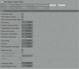
— Figure 2.42: Part of the Sky object settings.
The oZoNe value simulates the amount of ozone in the air. It causes the filtering of short-wave ultraviolet rays in the upper atmosphere, which, expressed in colors, results in a reduction of yellow and red sunlight. The sunlight therefore appears bluish with high ozone concentrations. The colors of the sky are not affected, though.
The iNteNSitY value controls the brightness of light generated by the sky. This has nothing to do with the depiction of the colors, the brightness of the sky, or even the INTENSITY of the sunlight. Therefore, the Night iNteNSitY rAtio affects only the depiction of the night sky with its stars. SAturAtioN CorreCtioN controls the coloring of the sky and the sky light. For example, at noon the sky is mainly blue and would create an intensely colored sky light. This value would then be used to reduce the coloring. With an extreme reduction of 0%, you would get only gray tones for the sky and its lighting. With COLOR CorreCtioN the color gradient can be moved within the color spectrum. That way, a reddish sky can also be shown at noon. With gAMMA CorreCtioN and As SeeN iNteNSitY, you can manipulate the brightness and color contrast of the sky. These values work just like the values used during the manipulation of an image in a graphics program. They also influence the INTENSITY of the night sky, but the illumination INTENSITY remains unchanged by these parameters. Only the brightness of the sky is changed.
The colors of the sky are generated internally with spectral colors. Its color space is not identical to the color space used by the commonly used RGB system. The conversion of the color values can therefore be influenced by the USE wArM COLORS and USE ChroMA COLOR Map options. USE wArM COLORS influences the conversion in favor of the red and yellow colors, while USE ChroMA COLOR Map results in a cooler sky with more contrast. These options can also be combined.
For our scene we set the iNteNSitY to 0%, so the sky color isn’t also used for the illumination, and select 11:00 a.m. for the time and 19 September 2008 as the date. For the city I chose Essen in Germany. These are rather spontaneous settings. Important only is the sun’s typical position on a late summer day.
In order to have the sunlight shine through the window, the side of the room with the windows should point south, which means to be oriented in the direction of the negative WORLD Z axis. Therefore, turn the entire room if necessary. Figure 2.43 shows an example of how the light shines into the room and what influence the sky object has on the illumination. As you can see in the left image, the blue color penetrates the walls and causes the coloring of the room to be too intense. This wouldn’t bother us with an outside scene, but in our case it looks unnatural. On the right side of Figure 2.43 you can see the same scene after the deacti-vation of the iNteNSitY of the sky. The interior is now lit only by the sunlight.
To intensify the sunlight, the glass object in the window should receive a COMPOSITING tag. It can be found after right clicking on the object in the OBJECT MANAGER in the context menu under the CINEMA 4D TAGS. Deactivate the CASt ShAdowS and reCeive ShAdowS, and also the SeeN BY Ao option, so any shadows cast by the glass will be suppressed.
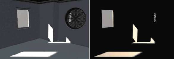
— Figure 2.43: With and WITHOUT sky illumination.
THE SETTINGS OF THE SUNLIGHT
The illumination of the scene is now entirely created by the SuN in the SkY object. The SuN of the SkY object has many properties that are comparable to those of a simple area light with area shadows. The option USE wArM COLORS works in a manner similar to its corresponding option in the settings of the sky. The conversion of the color values to the RGB color space shifts the colors to yellow and red tones. iNteNSitY represents the brightness of the sun and therefore the brightness of the illumination. I will use a relatively high value of 180%, since the sun is our only light source so far and I’d like to portray a strong contrast inside the room. The SAturAtioN CorreCtioN pertains to the coloring of the sunlight. At 0% you will get a white light. hue CorreCtioN and gAMMA CorreCtioN work like the corresponding settings for the sky. SiZe rAtio controls the size of the visible body of the sun and therefore also the size of the area of the light from the sun as well. A larger sun will generate a softer shadow and a smaller sun will cast harder shadows. As SeeN iNteNSitY scales the visibility of the body of the sun in the sky. This has no influence on the illumination by the sun. If you are bothered by the look of the sun, you can set the As SeeN iNteNSitY to 0% and the sun will disappear.
With CuStoM COLOR activated, the sun can be given custom coloring. Otherwise, the Preview COLOR in the upper part of the section shows a preview of the sun’s color set by the parameters. Additionally, leNSFlAreS can be added to the look of the sun, simulating the interaction of the sunlight with a camera lens. With CuStoM SuN OBJECT any other object can be used as the sun object. Simply pull it from the OBJECT MANAGER into the matching field in the SuN section. The remaining settings of this section are the same as the shadow settings of a normal light source with shadow maps and don’t need further explanation. Here you can set the type, color, and level of precision of the shadow calculation.
PLACE YOUR OWN SUN
As previously mentioned, you can use any other object as the sun. Just pull the object, with drag and drop, into the CuStoM SuN OBJECT field in the SuN section of the SkY object. Then DELETE the object again from the field by using the CleAr command in the menu on the right. This has the advantage that you can move the object yourself, for example, to pull it closer to the WORLD origin along its Z axis. Another more practical variation is to place an area light at the spot where the HUD element of a compass rose is positioned. The left side of Figure 2.44 shows this position marked with the mouse pointer. When you then orient the Z axis of the light source toward the origin of the WORLD coordinate system, as shown on the right in the figure, then you can move the light source yourself along the Z axis to the desired position. An advantage here is that you don’t have to depend on the settings of time and place from the SkY section. Your own light source can be moved a bit until an optimally cast shadow is achieved. Special functions can also be used, such as creating a falloff.
Don’t forget to deactivate the SuN of the SkY object so you don’t have two suns and cast two sets of shadows in your scene. Change to the BASIC settings of the SkY object and deactivate the SuN option. Here there are other options, like the one for activating atmospheric effects, fog, rainbows, or clouds. With the light source I placed, I used the iNFiNite type and AreA shadows. I set the iNteNSitY to 125% with a slight yellow coloring. Figure 2.45 shows you the placement of my own sun. The direction of the light corresponds with that of the original sun from the sky object. Only the TYPE of the light and the distance to the room are now different.
Figure 2.46 shows two variations that were achieved by simply changing the type of light. On the left you can see the iNFiNite light, and on the right a normal SPot light. The brightness, as well as the shadows, can be varied by changing the distance of the light source to the object. I will keep the iNFiNite light, though, since it comes closest to the illumination properties of the sun.
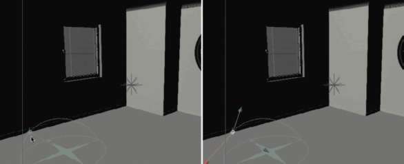
— Figure 2.44: Position your own light source.
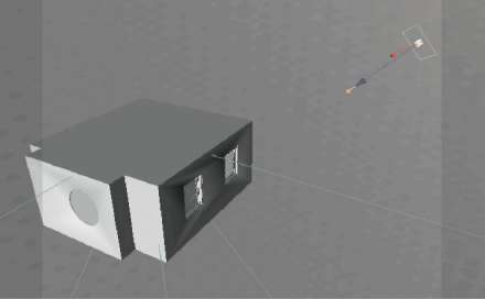
— Figure 2.45: Positioning your own sun.
Manually Illuminating the Room
Before we take a look at the lighting using gloBAl ILLUMINATION of the AdvANCed RENDERer, we will try to light the room with standard light sources. The sunlight has already been replaced by a normal light source. This light represents only the direct light part of the sun, though; the light scattered in the environment is missing completely. One part of this scattered light comes from all directions of the sky and thus finds its way through the windows into the room. This light generally has a blue tint and of course comes mainly from above. The portion of sunlight reflected from the surrounding buildings will be discussed later.
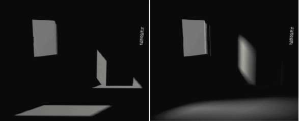
— Figure 2.46: Variations of the sunlight source.
We will add a new AreA light and change the shape of the light to heMiSPhere in the detAilS settings. The size should be large enough so the scene has enough room under the hemisphere. Therefore, increase the value for outer RADIUS in the detAilS settings of the light source. These settings and the result can be seen in Figure 2.47. The INTENSITY of 25% is quite moderate but is enough to give the room more definition. The shadows should be deactivated. Defined shadows with this kind of diffuse illumination would be rather distracting. The option for the calculation of SPECULAR should generally be deactivated in the geNerAl settings of such diffuse light sources. Only small lights add a believable highlight to surfaces.
THE SCATTERED LIGHT FROM THE ENVIRONMENT
As already mentioned, the sunlight is also reflected by other objects in the environment of the room. The surface of a house in direct sunlight would reflect a large amount of that light to the houses across from it. We will simulate this scattered light with two rectangular area lights that are placed outside, a certain distance away from the front of the windows. These lights will be used to calculate a shadow as well. I decided to use an AreA shadow again since it looks the most natural.
Figure 2.48 shows on the right where I placed these area lights and on the left you can see my settings. Note that the calculation of SPECULAR should be deactivated. In addition, I increased the CoNtrASt value in the detAilS settings of the light source to 50%. This causes a less-soft illumination and sharper transitions between light and shadow. I used a slightly yellow tint for the coloring of the lights.
Inside the room itself there is a kind of scattered diffuse light, because all the light is reflected by the floor, walls, and ceiling to other parts of the scene. Instead of using multiple additional lights, I used a spherical AreA light in the center of the room as it is defined on the left in Figure 2.49. A temporary iNteNSitY of 50% with a warm coloring of the light causes the illumination seen on the right in the same figure. This light source doesn’t have any highlight properties and doesn’t cast shadows. A shadow coming from the center of the room would look funny anyway. Again, we will use a contrast of 50% with this light source for more defined shadings.
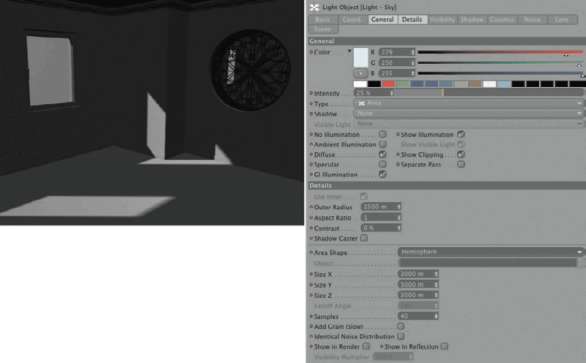
— Figure 2.47: Settings for the sky light.
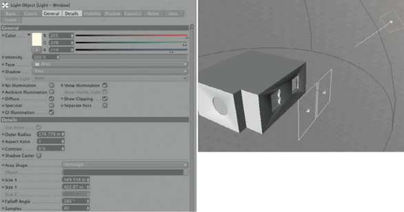
— Figure 2.48: Adding scattered light to the environment.
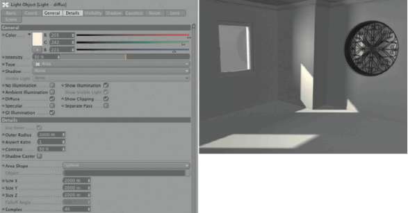
— Figure 2.49: Simulating diffuse scattering inside the room itself.
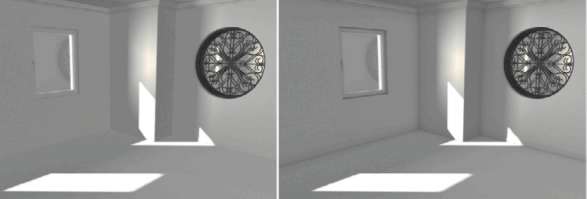
— Figure 2.50: The room with and WITHOUT Ambient Occlusion calculation.
Now you have a manageable number of light sources whose intensities can easily be adjusted to get the desired result. You can see in Figure 2.50 how the general increase of all intensities quickly gives us a good outcome. But at the same time, the increased brightness of the light sources WITHOUT shadows cause a decrease in definition and three-dimensionality. The transitions between floor and walls take a back seat.
We can counteract this with the AMBieNt oCCluSioN calculation. Activate this effect in the RENDER SettiNgS of CINEMA 4D and reduce the CoNtrASt value to –75%. Room corners that are too dark would look unnatural in a room flooded with sunlight. The right side of Figure 2.50 shows the result with otherwise unchanged lighting. The room corners, as well as smaller DETAILS like the crown molding, are now more pronounced and allow the room to appear more substantial. The described settings of the AMBieNt oCCluSioN are also documented in Figure 2.51.
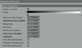
— Figure 2.51: Settings for the Ambient Occlusion in the render settings.
COLOR MAPPING
Especially with illumination by several light sources, but also with global illumination, parts of the image can be overexposed and too bright. In order to correct this you have several possibilities. You could adjust the brightness of the light sources until the brightness is at the correct level, but this could change well-lit areas as well. In addition, this process is time consuming in scenes with many light sources. The second possibility is to render the image in 32 bit color depth. This gives you enough leeway in postproduction to correct the illumination. Because the file size of the rendered image would increase tremendously, this method would be suitable only for still images and less so for animations. The third possibility is the use of the COLOR MAPPiNg post effect.
Figure 2.52 shows an example of the parameters used and how they affect the rendered image. The cores of these controls are two values: dArk MultiPlier and Bright MultiPlier. The effects are quite different from what the names might imply. An increase of the dArk MultiPlier value brightens the image and an increase of Bright MultiPlier darkens it. In any case, the effect causes a redistribution of brightness values in the image and helps to get good results, even with heavily overexposed images. When hSv MODEl is active, only the brightness of the colors of the image is changed, not the color or saturation values. If a background image or sky is to be excluded from the post-effect calculation, then deactivate AFFeCt BACkgrouNd. Lastly, the eXPoNeNtiAl option creates an exponential transition between light and dark parts of the image. Without this option the transition would be calculated in a linear fashion.

— Figure 2.52: Illumination correction with color mapping.
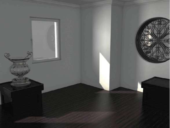
— Figure 2.53: The result of traditional illumination with light sources.
Figure 2.53 gives you an impression of how the room could look with the wooden floor texture and the added objects. With a little effort we can get good results, even with normal light sources.
Global Illumination
As we have seen in the first chapter, there are certain options available in the AdvANCed RENDERer for calculating global illumination. By knowing the type of illumination and the scene, we can exclude some methods that are less well suited. The gi MODE QMC offers the highest quality since every pixel is treated in the same way, regardless of its position in the scene or its visibility to the light sources. This calculation needs many steps and takes longer to create results with low noise. In this regard the ir mode can’t be beat because CINEMA 4D itself optimizes the number of calculation steps per image pixel. This optimization is traded, though, with a softer, and therefore less accurate, light distribution. Then there is the special SkY SAMPler, which is meant to be used for outside scenes and exclusively calculates the direct illumination by the sky or an HDRI image.
Due to the functionality of these modes, the IR mode is primarily used for interior spaces. A combination mode of IR and QMC is an alternative to the sky sampler for outside scenes. The QMC mode can be used for all scenes, but creates more noise than other modes in the same amount of render time. However, this style might be the one you want for the final image.
GENERAL SETTINGS
To illuminate our room we will select the IR mode. It is short for Irradiance Cache. This GI mode is activated in the geNerAl settings of the global illumination after activation of the GI by clicking on the eFFeCtS button in the RENDER SettiNgS. The next setting in this mode concerns the diffuse depth, which determines how often a ray is reflected off and forwarded from a surface. The higher the diFFUSE dePth, the more the light is scattered and directed to previously shaded areas. The image gets brighter with increasing diFFUSE dePth and needs more time to render. We will use a value of 2.
The PriMArY iNteNSitY is a multiplier for the brightness of the first light reflection. What’s important is whether the scene is lit by a light source or by an illuminated object. With a light source, the directly illuminated surface is not included in the calculation of the global illumination and therefore also not included in the PriMArY iNteNSitY. Only the reflected light from the directly illuminated object is multiplied with this value. It is different with lighting from an illuminating material. Here, the light generated by the illumination is included in the global illumination calculation and also multiplied with the PriMArY iNteNSitY. At diFFUSE dePthS over 1, the light INTENSITY of subsequent light reflections can be controlled by SeCoNdArY iNteNSitY. We will leave the two values at 100% for the moment. A gamma value can be used in addition to either darken or lighten the whole image. Values above 1 generally lighten the result and can, in some cases, save us the time needed to adjust the light sources or material properties of the scene. Values under 1, of course, reduce the image brightness. As you can see on the left of Figure 2.54, we will keep the standard value of 1.
IRRADIANCE CACHE SETTINGS
In IR mode, so-called pre-passes and shading points are calculated and light distribution is interpolated between these two. To optimize the render time, there are several parameters available to achieve a balanced ratio between quality and render time. The meaning of these parameters was already explained in the first chapter, so I will just list the functions and the settings used for our scene. You can find them on the right of Figure 2.54.

— Figure 2.54: Settings for global illumination.
StoChAStiC SAMPleS represents the number of calculation rays per diFFUSE dePth and pixel that are being sent into the scene. We will use the preset low. reCord deNSitY takes care of the density of shading points. These points are then evaluated for the interpolation of color and brightness values of the finished image. This means that the result is more precise because more shading points are generated. Of course, this also increases the render time. As a result, we will first try our luck using the low setting to obtain a quick preview of the global illumination.
The iNterPolAtioN Method defines, together with the SMoothiNg setting, the algorithm that is used to calculate the smoothness of the determined shading points. We will use leASt SQuAreS with a medium SMoothiNg. The overSAMPliNg is used when illuminating materials or GI portals are used if those materials were activated by using overSAMPliNg as SAMPle MODE on the ILLUMINATION page. The setting weAk should be sufficient for now.
The diStANCe Map option ensures that the distance between objects is taken more into consideration, thereby preventing light from penetrating objects in close proximity. Because of the double walls in our room we don’t need this setting. CheCk reCord viSiBilitY works the same way and also prevents light from penetrating single-walled objects. We can forego this setting as well for the same reason. detAilS eNhANCeMeNt works in a manner similar to the AMBieNt oCCluSioN calculation and can prevent the weakening of fine shadows that are caused by indirect light. We will activate that option.
ADJUSTING THE SETTINGS OF THE SKY OBJECT
Deactivate or DELETE all light sources in our scene. Then open the dialog of the SkY object and activate the SuN and SkY in the BASIC settings. Set the iNteNSitY in the SkY settings to 100% so its light is included in the calculation. In the settings of the sun we will use an iNteNSitY of 180%. All other settings previously set stay the same. The SkY object is now the only light source in the scene. Now make a test rendering of the scene. The result is quite sobering, as you can see in Figure 2.55. Besides the direct light of the sun, there is hardly any evidence of indirect illumination. Maybe our settings in the RENDER SettiNgS are too low?
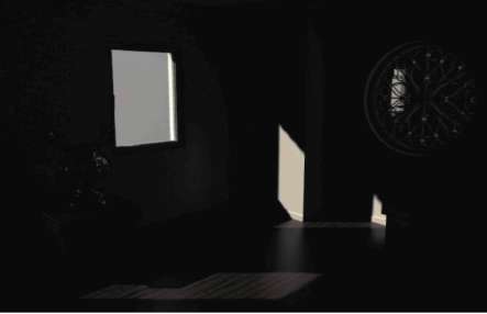
— Figure 2.55: First render tests with global illumination.
Let us try it again, but this time with a PriMArY iNteNSitY of 200%. The brightness of the light reflected from the walls and the floor should now be twice as strong. Figure 2.56 disappoints us again. The differences are minimal. What could be the reason? During analysis, it helps to put yourself in the position of the light. Therefore, enter the room through the window and you will encounter the side wall and the floor first. This light is not yet generated by global illumination and is therefore shown correctly in the results. The first reflection starts either from the floor or the wall, from where it probably hits the floor again. The problem of the dark illumination is caused by the dark material of the floor. Remember, light doesn’t consist entirely of brightness, but also of color values that are transferred by the reflecting light from one object to another. When a dark object is illuminated, then only dark light is reflected, regardless of the INTENSITY of the incoming light. What should we do? We like the look of the dark wooden floor and don’t want to replace it with a light one.
OPTIMIZING THE FLOOR FOR GI
In cases like this we have to use a trick. We will solve the problem by using two separate objects. One will represent the visible floor and the other one will take care of the reflection of the light back into the room. In order to do this, we will select the floor polygon in our room and choose the diSCONNECT command in the FUNCTIONS menu. This creates a new object that contains only the floor surface. If your room object has subordinated objects in the OBJECT MANAGER, then these objects are copied as well and are placed in a hierarchy under the newly added and disconnected object in the OBJECT ManAger. You can DELETE these duplicate objects. Also DELETE the floor polygon in the original room object.
Duplicate the previously disconnected new floor object and shrink it, by moving the corner points, so it shows a consistent gap to the baseboard all the way around. Figure 2.57 shows the shrunken object in two viewports. You can see the desired gap between the baseboard and the edge of the shrunken floor on the right. We do this because the baseboard should not be illuminated too much by the reflecting light. This would look unrealistic with such a dark floor. Also, pull the shrunken floor slightly beneath the original floor of the room. A minimal movement of maybe 0.1 units downward is enough so that the two floor objects don’t occupy the same space.
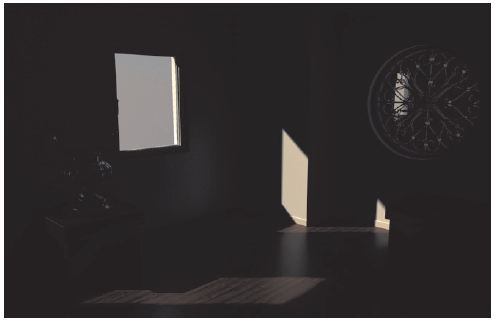
— Figure 2.56: The result after doubling the primary INTENSITY.
In order to let CINEMA 4D know which object has what function, add a COMPOSITING tag to each floor object, as shown in Figure 2.58. Add them with a right click on the objects in the OBJECT MANAGER and by choosing CINEMA 4D TAGS>COMPOSITING. Also, remember that the object representing the visible floor can be removed from the now unnecessary TEXTURE and SELECTION tags. Only the material for the floor texture should remain. The entry for the limitation to the polygon selection has to be removed from the TEXTURE tag as well. The second lower floor object doesn’t receive a material.
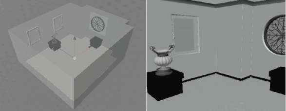
— Figure 2.57: Creating a double floor.
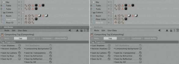
— Figure 2.58: Compositing tags for both floor objects.
In the compositing tag of the textured floor, deactivate CASt ShAdowS and SeeN BY gi. Otherwise, this object would cast a shadow onto the lower floor, making its function more difficult. The lower floor, on the other hand, should not be visible for AMBieNt oCCluSioN and shouldn’t react to shadows. As a result, deactivate CASt ShAdowS, reCeive ShAdowS, and SeeN BY Ao. SeeN BY gi needs to stay activated.
The positive change caused by this little tweak can be seen in Figure 2.59. The light can now be reflected by the floor and illuminates the room. Even the low detail and sample values seem to work well in this case and don’t need to be increased. Like in the previous scene, I used AMBieNt oCCluSioN in the RENDER SettiNgS to increase the DETAILS in the room corners and behind the side tables. This time I reduced the maximum ray length from 100 to 30 units, to further inhibit the darkening of the corners. This value depends mainly on the scale of your room, so it is too difficult for me to provide binding values. You will have to run some test renderings to find the right value.
Another try can be seen in Figure 2.60. There I set the diFFUSE dePth to just 1, but with a PriMArY iNteNSitY of 200% and a gAMMA of 1.8 to compensate for the removal of the second reflection of the light. This increases the render speed considerably. A slightly red tint of the lower duplicated floor results in a warmer, more diffuse color. Just remember that this coloring should be subtle so the illumination isn’t reduced. Such color correction can also be done in postproduction, when corresponding Multi-Passes have been saved separately.
AN ALTERNATIVE LIGHTING MOOD
In the previous example we simulated sunlight streaming through a window. I would like to change the scene now to simulate illumination from a torchiere in the room, WITHOUT any light coming in from the outside. In the first step, remove the Sky object completely from the scene, so neither sunlight nor skylight is generated. The illuminated interior will look more realistic at night; therefore, we also don’t need the gradient of the sky anymore.
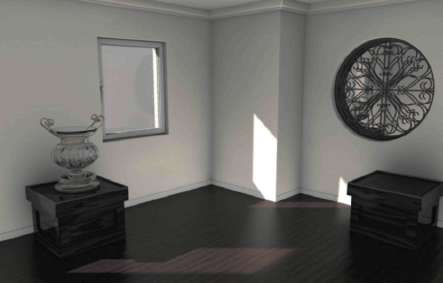
— Figure 2.59: Changing the room illumination after adding the second floor.
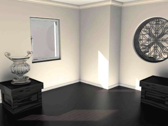
— Figure 2.60: Variations of the result.
Modeling the Torchiere
For the torchiere we will model a playful shape from splines. I used a B-SPliNe as shown on the left of Figure 2.61. Together with a CIRCLE spline, I subordinated the spline under a SweeP NURBS object. As you can see in Figure 2.61, I shaped the spline in such a way that it creates a vase-like and bulbous shape, with spheres placed in the middle as decorative elements. Using an ArrAY object from the OBJECTS>ModeliNg menu, create five copies of the Sweep NURBS. These are automatically arranged in a circular manner as long as you have placed the Sweep NURBS in the XY or XZ plane. Figure 2.61 shows the necessary hierarchical structure of the objects and a possible shape of the torchiere.
The object can be made more interesting with a deformation. We will use a twiSt object found at OBJECTS>deForMAtioN. It has to be subordinated under the ArrAY object, at the same level as the Sweep NURBS object. It is important, though, that the Sweep NURBS object is still on top of the list, as shown in Figure 2.62. Adjust the Y size of the deformer so it runs along the WORLD Y axis and encloses the bulbous part of the lamp. A direCtioN value of 270° in the twiSt settings in the ATTRIBUTE MANAGER will generate a twist, as shown in Figure 2.62.
The illumination component is positioned on top, inside a translucent bowl that we will model from a simple cube, as shown on the left in Figure 2.63. Then we will convert the cube, using the (C) key, to a POLYGON object and switch to USE POLYGON tool mode. Select the two large caps, on top and bottom, with the live SELECTION in the top viewport and make it possible to select hidden elements. After that use eXtrude iNNer, from the StruCture menu, multiple times with these faces so you can have multiple subdivisions, as shown on the right in Figure 2.63.
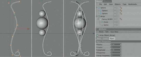
— Figure 2.61: Modeling a torchiere.
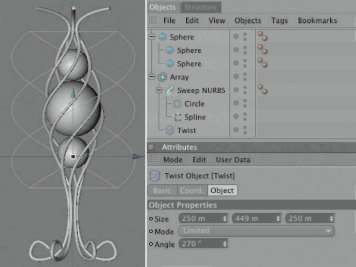
— Figure 2.62: Adding a twist object.
The newly generated points can be used to change the cube into a funnel-like shape, like the one shown in Figure 2.64. Remember to select and move simultaneously the points on the top and bottom of the cube so the thickness of the object remains constant. By subordinating the deformed cube under a hYPerNURBS object it can be smoothed, as shown on the right in Figure 2.64. An alternative to this modeling method is the use of a LATHE NURBS object with a profile spline of the reflector bowl. The principle is the same as the modeling of the vase in the previous chapter. There are always several ways that lead to the finish.
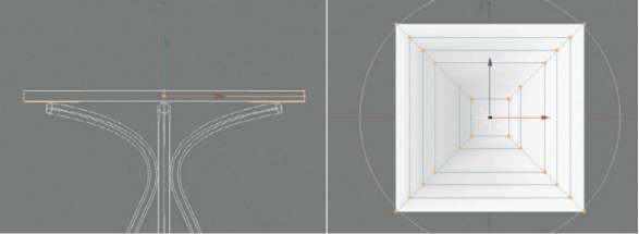
— Figure 2.63: Modeling the reflector.
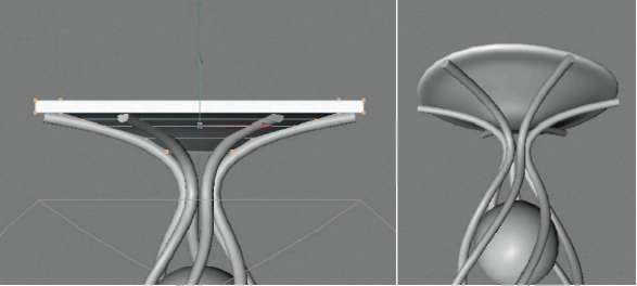
— Figure 2.64: Shaping the reflector.
Still missing is the actual light source. For that we will use a point light with a soft shadow. It is important that the light source is located deep enough in the upper funnel of the torchiere so the direct light exits in a wide cone upward toward the ceiling. Figure 2.65 shows the positioning of the light source and the preliminary settings.
Then group all elements of the lamp together in order to move or scale them more easily. Select all objects of the lamp with (Ctrl) clicks in the OBJECT MANAGER, or by using a selection frame in the OBJECT MANAGER, and by selecting grouP OBJECTS in the OBJECTS menu of the OBJECT MANAGER. Afterward, position the torchiere in a corner of the room next to the window or in another spot of your choice.
The Materials of the Torchiere
The frame of the lamp receives an understated dark material with a slight reflection. You could use the same material used for the decorative grid. The spheres enclosed in the lamp are supposed to be transparent, but at the same time very refractive and reflective. We will create a new material and set the brightness to 50% in the COLOR channel so the reflective properties can be easily seen. I colored the transparency slightly orange and assigned a REFRACTION index of 1.6 with a BrightNeSS of 70%. As ABSorPtioN COLOR I used a desaturated blue whose ABSorPtioN diStANCe is adjusted to the radius of the sphere. Only test renderings help to find the correct settings. The value could be roughly oriented to the diameter of the largest sphere. The options for totAl iNterNAl REFLECTION and EXIT REFLECTIONS are activated as well.
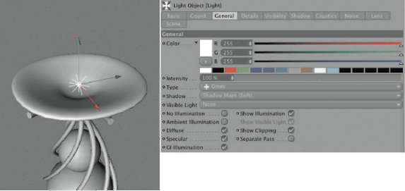
— Figure 2.65: The light source for the torchiere.
The color of the reflection is a slight yellow and has a brightness of 70%, with the highlight being intense and small. Since the material has mainly reflective and transparent properties, generating and receiving global illumination can be deactivated. Figure 2.66 shows the most important parameters of this material.
The Refector Material
The upper reflector bowl is supposed to consist of a translucent, slightly transparent material. We will start again in the COLOR channel of a new material. I loaded the NoiSe shader and used two slightly different color tones in the yellow-red range of the color space. For the NoiSe type I used eleCtriC, but other patterns are possible, too. The goal here is to show slight irregularities in the surface color. In the COLOR channel itself I reduced the MiX STRENGTH to 50% so the standard gray color of the channel is visible through the NoiSe, thereby weakening the NoiSe a bit.
Subsurface Scattering
The chief characteristic of this material is not the surface color, but instead the illuminating part. Therefore, we will use the SuBSurFACe SCAtteRING shader in the LUMINANCE channel. This shader can simulate continuous and scattered light within an object. Just think about the effect that occurs when you hold your hand in front of a lamp. The light passes partially through the fingers, causing them to glow red at thinner parts. This effect is caused by the scattering of light within the objects and is characteristic of many organic, but also inorganic, materials. Even massive rocks and marble show that effect in nature. The SuBSurFACe SCAtteRING shader, or SSS shader, can be found in the effects group of the shader and is controlled mainly by entering lengths. The size of the object that is supposed to receive this shader is very important. The SCAtteRING leNgth defines the distance that a ray can travel within an object. This parameter is generally smaller than the dimensions of the object. ABSorPtioN represents the medium distance from where the light is scattered. An ABSorPtioN value that is too big reduces the influence of the ABSorPtioN Filter.
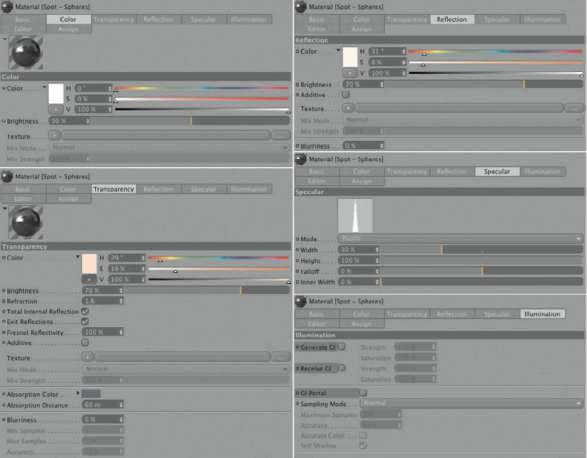
— Figure 2.66: The glass sphere material of the lamp.
The ABSorPtioN Filter defines the coloring of the scattered light at the various depths of penetration into the object. The left edge of the color gradient stands for the coloring in the thinnest SEGMENTS of the object and the right one for the thickest parts. The color gradient orients itself based on the value for the Filter leNgth. The colors placed on the right side in the gradient will be visible after the scattered light distance defined in the Filter leNgth. The STRENGTH value is a simple multiplier of the effect’s brightness. The SAMPleS stand for the number of calculation steps per surface point. Higher values generate a result with less brightness noise, but it also takes longer. Lastly, MiNiMAl thiCkNeSS defines the distance that a ray can travel through the object, measured from the surface, WITHOUT scattering or losing its strength. Since the shader has to know if the ray is still traveling within the object or maybe within a cavity in order to calculate, the direction of the normals is important. With USE NorMAlS active, the normals pointing outward are automatically recognized as the outer shell of the object. Without this option, the shader just counts the penetrated polygons and assumes that between the first and second (third and fourth, and so on) penetration the object is solid. This method is quicker when using simple geometries. A summarization of my settings can be seen in Figure 2.67.
We can also use a slight REFLECTION of 10% in the material WITHOUT a blurry effect. As for the illumination, reCeive gi and geNerAte gi should be active. I reduced the generating property to just 10%. This value is a result of multiple test renderings. You can leave this value at 100% and lower it later, based on your own needs. This value is important because illuminating materials act like light sources in the global illumination calculation and take part in the actual lighting of the environment. I reduced the receiving value to 80% and the SAturAtioN of the received GI light was reduced to 50%. The reflector itself emits light and therefore shouldn’t absorb that much color of the other elements. It is also important to activate the Sampling MODE since we are dealing with an illuminating material. This setting makes sure that the calculation rays are focusing more on this material. The oversampling setting should be precise enough. Figure 2.68 shows all these settings again.
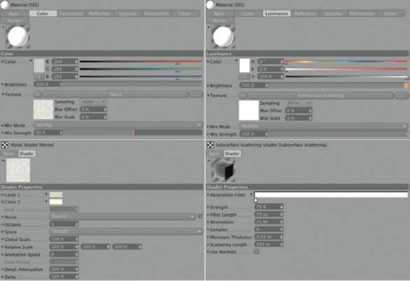
— Figure 2.67: The material of the reflector.
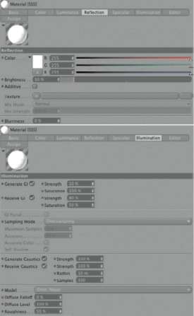
— Figure 2.68: More settings of the reflector material.
First Test Renderings
Before we start with the settings for the global illumination, we should test the brightness of the real light source in the reflector. You have to keep in mind that its light, depending on the diFFuse depth used, will be much brighter. Also, this light is added to the emitted light of the illuminating reflector. Besides reducing the light source INTENSITY, you should also use the falloff feature. Figure 2.69 shows my settings.
I used an inverse Falloff with a radius that reaches roughly from the light source to the corner of the room. The radii on top left of the figure indicate this distance. An INTENSITY of just 10% might seem very small but will be balanced by the previously mentioned characteristics of global illumination. Figure 2.69 shows the result in the upper right. The light cone of the lamp and the brightness of the reflector bowl can already be seen clearly.
Settings of the Global Illumination
You can always check, during the prepass calculation, whether the lighting is the way you imagined it to be or if the rendering should be stopped and repeated after changing the settings. Figure 2.70 shows such an early phase of the prepass calculation, which appears after just a few seconds. Already you can judge the brightness distribution and INTENSITY WITHOUT having to wait a few minutes for the finished image. You should also deactivate Anti-Aliasing and Ambient oCClusion during test renderings to achieve a fast result.
We will now activate global illumination in the eFFects of the render Settings and start with ir (Still image) mode and a diFFuse depth of 1. When the Primary INTENSITY is increased to 300% you will get a result as shown in Figure 2.71. This is far from realistic lighting, but that wasn’t the goal of this first step. Instead, we are trying to create a transition of brightness between the light source and the walls of the room. We can already see—even if it is still very dark—how the walls are lit by the global illumination.
We could keep increasing the Primary INTENSITY value until we have sufficient image brightness, but it is easier to use the gamma value. In the result shown in Figure 2.72, the gamma value was increased from 1 to 3 while all other settings remained the same. The room is quite realistically illuminated, but it also is apparent that the brightness above the reflector is too intense. We can correct this with the help of COLOR MAPPiNg, found in the effects of the RENDER SettiNgS. It reduces the brightness to eliminate overexposure. With the standard values of 1 each for dArk MultPlier and light MultiPlier, the image will probably be too balanced. The maximum brightness should still be located above the lamp. Consequently I used a value of 1.5 for dArk MultiPlier to increase the overall brightness. A slight increase of light MultiPlier to 1.05 increases the contrast between the light walls and the dark wood of the floor and side tables. Figure 2.72 shows the result. We are going in the right direction.
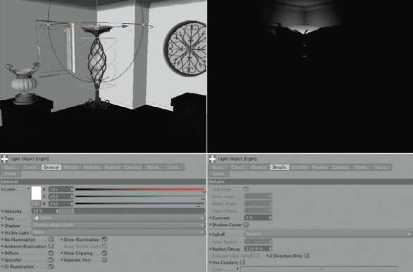
— Figure 2.69: The light source of the torchiere.
— Figure 2.70: The prepass of the global illumination.
The result can be improved even further by using an additional diFFUSE dePth. On the left of Figure 2.73 you can see the result with a diFFUSE dePth of 2, a PriMArY iNteNSitY of 300%, and a SeCoNdArY iNteNSitY of 100%. Next to it is the finished image with 200% SeCoNdArY iNteNSitY. The irrAdiANCe CAChe values can be seen there as well. Nothing has changed here in comparison to the illumination by sunlight. Medium standard settings result in a good quality.
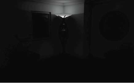
— Figure 2.71: First test renderings with global illuminations.
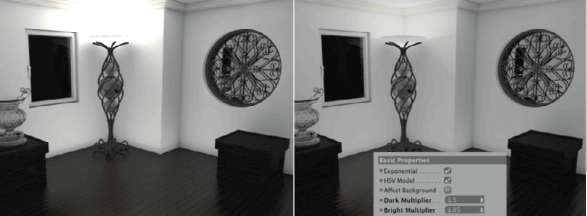
— Figure 2.72: Using the gamma value to increase the overall brightness.
Keep in mind that these render settings might have nothing to do with the simulation of realistic light. It is our goal to achieve a good result from an artistic viewpoint within a reasonable time frame. Using a photo of a real illuminated room, it would of course be easier to replicate the distribution of different brightness levels. We have to trust in our own judgment and abilities to find the right mood for the image.
Figure 2.74 shows the final image after the reactivation of AMBieNt oCCluSioN and a correction of the tonal value in postproduction.
With the following example we will leave the constricting scene of a room and step outside.
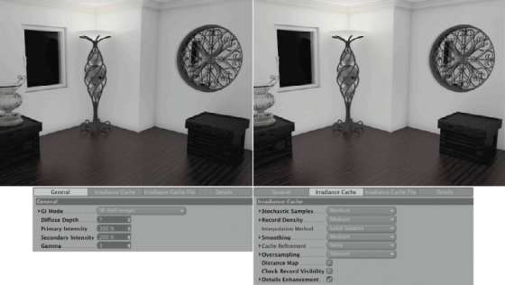
— Figure 2.73: Settings for the global illumination of the final rendering.
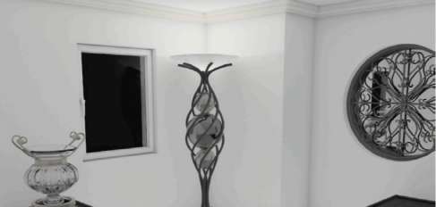
— Figure 2.74: The final result of the interior lighting.
Lighting an Outdoor Scene
The theme of this new workshop is the lighting of an outdoor scene that consists mainly of stairs that are lit along the side by lanterns. We will take our inspiration from traditional temples in Japan and use existing shapes when modeling the lanterns. You will discover again how quickly complex-looking shapes can be made using simple shapes. Afterward we will model the rustic stone stairs with the help of NURBS objects and Deformer objects.
Modeling the Lantern
We start the modeling of the lantern with the base plate, located between the post and the upper part that will later contain the light. Under this square plate, which has been built from a flat CuBe object, we will place an elongated cube in a diagonal direction, as shown in Figure 2.75. Here you can also see the measurements I used if you don’t trust your own visual judgment. I didn’t work with predetermined measurements, but instead with reference images of similar lanterns that I researched on the Internet.
Be sure to round all objects slightly. This will look more natural in the rendered image. Even if the number of polygons will increase considerably, it is worth it. Now convert the diagonal beam using the familiar (C) key and activate the kNiFe tool in the StruCture menu. In order to use that tool you have to work in USE POINT TOOL, USE edge tool, or USE POLYGON tool mode.
Add two looP cuts to the beam. One is placed exactly in the center and one just before the spot where the beam comes out from under the plate. In USE POINT TOOL mode, DELETE the end of the beam completely, as shown on the left in Figure 2.76. You can use the FRAME SELECTION to select all points on one side of the beam and then DELETE them with the (Delete) key. Just make sure that your mouse pointer is placed above the viewport and not over the OBJECT MANAGER; otherwise, the whole object will be DELETEd and not just the selected points. In addition, the selection of hidden elements should be allowed. Select the lower outer points at the end of the beam and move them slightly upward. The beam will be tapered at its end, as shown in the different views in Figure 2.76.
In USE MODEl tool MODE create three copies of the shortened beam and rotate each by 90° around the Y axis. Because the original beam was positioned in the center of the square plate and the local axis system wasn’t changed by deleting points, it should be possible to rotate the copies around the center of the plate. In the end, the four beams should be positioned diagonally under the plate as shown in Figure 2.77. Then create another cube, which is elongated along its HEIGHT, to serve as a short post that we can place in the center of the plate. Because the four beams enter the post in the center, we don’t have to close the open ends created by the deletion of the beam points.

— Figure 2.75: Base plate and supporting square timber of the lantern.
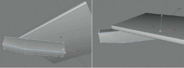
— Figure 2.76: Tapering and shortening the lower support beam.
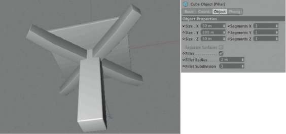
— Figure 2.77: The complete base of the lantern.
THE FRAMEWORK OF THE LANTERN
This completes the base of the lantern, and now we will start on the framework. We will need four slim cubes, each pair having equal measurements. These cubes are placed parallel to the edge of the plate, on top of the plate. The ends of the cubes penetrate each other, as shown in Figure 2.78. The highlight shows the cubes with equal measurements. The HEIGHT of one pair of cubes is slightly reduced so no unnatural shading will occur at the corners of the intersecting areas of the cubes.
Exactly into one of the cross points of the cubes we will place a new vertical cube whose profile corresponds with the four previously placed cubes. Set the HEIGHT of the cube so it has the HEIGHT you envisioned for the lantern. Figure 2.79 gives a reference and shows again the measurements I used.
— Figure 2.78: The lower support construction.
Using the (C) key, convert the vertical cube to a POLYGON object and change to USE OBJECT AXiS tool mode. With the MOVE tool pull the axis system of the cube downward, so that it is positioned approximately at the cross point of the cubes lying on the plate. Back in USE MODEl tool mode, activate the rotAte tool and rotate the vertical cube slightly outward. Figure 2.80 shows this tilt from several views. As you can see there, the cube isn’t rotated outward into the direction of the base plate corner, but only around one of its object axes. I decided to rotate it around the Z axis, but it doesn’t really matter which one is used.
When you are happy with the tilt and rotation of this vertical support beam, create three copies in the OBJECT MANAGER by using the (Ctrl) key with drag and drop. MOVE these copies to the three other cross points on the base plate and create a symmetrical tilt of the beams by changing the signs in the COORDINATE MANAGER. This means that, when you previously rotated the vertical cube around its Z axis by 4°, you then have to change the numerical value of the B angle in the COORDINATE MANAGER from 4° to –4° to create a mirrored tilt.
— Figure 2.79: The vertical beam.
— Figure 2.80: Rotating and duplicating the vertical support beams.
Modeling the Upper Immediate Ceiling
In order to give this construction stability, we will add another four cubes slightly beneath the upper ends of the vertical support beams. This time, though, they are not modeled from several objects but from one flat cube, as shown in Figure 2.81. The HEIGHT of the cube is equal to the profile of the vertical support beams. Make sure that this plate protrudes on all sides, slightly past the support beams. Because of the rotation of the support beams this plate cannot have a square base plane like the lower base plate.
— Figure 2.81: The upper intermediate ceiling.
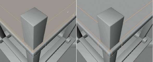
— Figure 2.82: Creating additional subdivisions using the Knife tool on the converted cube.
Convert the newly created plane with the (C) key to a POLYGON object and switch to the USE POLYGON tool mode. Using the kNiFe tool from the StruCture menu, make some looP cuts along the support beams that protrude through the plate, as in Figure 2.82. Select the polygons along the edge of the subdivided plate that are supposed to belong to the new, horizontal stabilization bar. Figure 2.83 clarifies which faces are meant.
After these faces are selected, use the diSCONNECT command in the FUNCTIONS menu to copy these faces into a new POLYGON object. The original plate can be made invisible for the moment. Use the CreAte POLYGON function in the StruCture menu to close the highlighted opening of the disconnected object, shown in Figure 2.83, with a quadrangle made of new polygons. To do this, click clockwise, in consecutive order, onto the corner points at the open edge of the object. On the fourth point double click so the new face is generated between the previously clicked points.
Use the same principle for the other sides of the subdivided plate. This creates four flat beams with cutouts for the vertical beams. Figure 2.84 shows these objects alone and then on the right side in connection with the other groups of the lantern. The highlights emphasize where the borders of the disconnected and then closed parts are located. Make sure that there are no intersections and that the four beams are exactly aligned, especially at the corners.
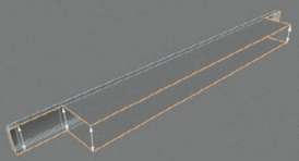
— Figure 2.83: Manual closing of the disconnected area of the plate.
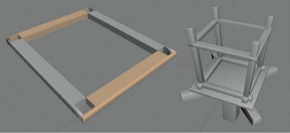
— Figure 2.84: Complete upper support frame of the lantern.
THE ROOF OF THE LANTERN
In the next steps we will put a typical roof on top of the lantern. We will start with the support structure, which again contains four cubes, two identical pairs. The longer cubes are used on the sides where the vertical support beams tilt outward. These elements can be seen in the upper part of Figure 2.85. Note the generous overlap of these highlighted cubes. The two shorter cubes are shown underneath. They are modeled taller so the faces at the cross points don’t intersect at the corners.
The actual roof consists of two cube plates with different angles that are placed, slightly overlapping each other, above the support structure of the lantern. Since the roof is symmetrical we only have to create half of the roof, as shown in Figure 2.86. Once you have modeled the lantern around the WORLD origin, then you can use the WORLD Y axis as the symmetry axis and align the tilt of the upper cube on it. The cubes should be adjusted in their WIDTH so that they also overlap the longer support beams a bit.
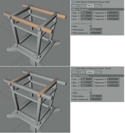
— Figure 2.85: The support beam for the roof construction.
— Figure 2.86: Simple roof construction from two cubes.
As I just mentioned, we don’t have to put in the effort to model the other half of the roof. A new SYMMETRY object with the two cubes of the roof subordinated under it will take care of that. Note that the SYMMETRY object only mirrors the uppermost subordinated object and its hierarchy. Therefore, create a hierarchical relationship between the two cubes of the roof construction under the SYMMETRY object, as seen in Figure 2.87. If the Mirror PLANE in the SYMMETRY object was set correctly, then you should now see the complete roof.
In order to have such a roof construction work, we need some connecting elements. We will use splines, because we need a bar that nestles against the two roof cubes. Figure 2.88 shows how such a spline curve could look. I used a Bezier spline and utilized its tangents to create roundings and hard edges. The spline should be closed with the CLOSE SPLINE option in the ATTRIBUTE ManAger so we can convert it, in the next step, to a solid-looking object with the help of an EXTRUDE NURBS.
— Figure 2.87: Symmetrical doubling of the half roof.
— Figure 2.88: Connection element of the half roof.
Create a new EXTRUDE NURBS object and subordinate the spline under it. Then make a copy of the spline and leave it in the group of the NURBS object, as shown in Figure 2.88. For the EXTRUDE NURBS object to utilize both splines you have to activate the hierArChiCAl option. Then use the MOVEMeNt value and the option for closing and rounding the caps to give the spline mass.
Pull apart both splines, located along the roof construction, so that evenly sized gaps are generated at the outer edges of the roof. Figure 2.89 can be used as an example. There you can see that the subordination of the EXTRUDE NURBS objects, in the roof group under the SYMMETRY object, automatically completes the missing side. The remaining gap between all NURBS objects at the peak of the roof is closed by a new cube object that is highlighted on the right side of Figure 2.89. In the front and back this ridge extends past the roof quite a bit. Don’t forget to round the cube here, too.
Despite all efforts, the roof construction still appears a bit shaky since a support from below is missing. To add it, start again with a new spline created in a linear manner. Depending on the orientation of your lantern, you will have to create the spline in the side or front viewport and use it to close one-half of the roof gable, as shown in Figure 2.90. Check in the COORDINATE MANAGER to be sure that the points in the center are positioned exactly on the symmetry axis of the lantern. The X and Y point coordinates should be 0 as long as your lantern was built at the WORLD origin.
— Figure 2.89: Adding the roof ridge.
The finished spline is then subordinated under a new EXTRUDE NURBS object. This time, leave the MOVEMeNt value at 0 and use only one of the two cap functions, as shown on the right side of Figure 2.90. This ensures that the closed spline of the half gable is closed by a face.
Select the EXTRUDE NURBS and convert it, with FUNCTIONS>MAKE EDITABLE, into a POLYGON object. Add a new SYMMETRY object from OBJECTS>ModeliNg and subordinate the converted EXTRUDE NURBS under it. As shown in Figure 2.91, one side of the gable should be completely closed, as long as you have moved the face of the EXTRUDE NURBS to an appropriate position.
The SYMMETRY object is also just a parametric object and can therefore be converted. Select the most recently created SYMMETRY object and use the (C) key to convert it to a POLYGON object. There should now be a POLYGON object with two faces in front of you, as shown on the left in Figure 2.92. This structure can be further simplified. Select the two faces in USE POLYGON tool mode and choose Melt in the FUNCTIONS menu. The two faces are then combined into one large n-gon, as can be seen on the right of Figure 2.92. If this doesn’t work with your object, then most likely the points in the middle weren’t located exactly on top of each other and haven’t been combined by the SYMMETRY object. In this case, use the uNdo function in the edit menu to go backward until you have the SYMMETRY object back. Select the points positioned on the symmetry plane and control their position.
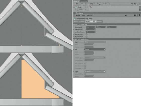
— Figure 2.90: Closing the gable.
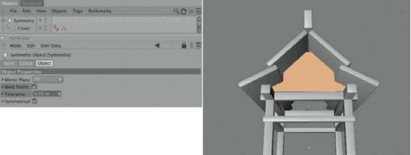
— Figure 2.91: Mirroring the converted Extrude NURBS object.
— Figure 2.92: Converted and optimized symmetry object.
Duplicate this closed object of the gable and move the copy to the opposite side of the lantern. The following steps will deal with the spaces in between. If we use a tea light candle for the illumination it has to be protected from drafts.
MODELING THE SIDE PARTS OF THE LANTERN
We will start by closing the remaining open areas on the sides of the upper portion of the lantern, in between the upper support framework. Create a new CuBe object, but this time we won’t need to round the edges since they will be completely covered by the surrounding cubes. Adjust the size of the cube so that it intersects slightly with the cubes around its perimeter. This will ensure that light will not leak through small gaps. Figure 2.93 shows the size and position of the highlighted cube.
Then convert this cube with the (C) key to a POLYGON object and DELETE, in USE POLYGON tool mode, the two large faces on top and bottom of the cube. What remains are the four side faces of the lantern construction. Select these four polygons and activate the eXtrude iNNer command in the StruCture menu. Deactivate the PreServe grouPS option in the settings of the command in the ATTRIBUTE MANAGER so that all four sides can be edited separately. Reduce the size of the selected faces, as shown on the top left of Figure 2.94.
Then deselect a facing polygon pair. Now only two faces that were shrunk with eXtrude iNNer remain selected. In the COORDINATE MANAGER reduce the value for the lateral size of these polygons and use the APPLY button. You could also use the SCAle tool that is restricted to lateral scaling. The goal is to get faces twice as wide as they are high. Repeat this with the second polygon pair generated by eXtrude iNNer. Figure 2.94 shows the desired result on the bottom left.
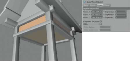
— Figure 2.93: Closing the upper segment.
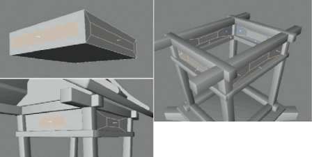
— Figure 2.94: Extruding side faces inward.
The shrunken faces located in the center of the side polygons represent windows that are covered with translucent glass or paper. The surrounding polygons build a solid frame that could be made of wood. Select the four shrunken faces in the center of the four sides and use INVERT in the SELECTION menu. The result is also shown in Figure 2.94 on the right. With this simple method the polygons surrounding the windows are now selected.
Select the eXtrude command in the StruCture menu and activate the CreAte Caps option in the ATTRIBUTE MANAGER. This will ensure that during the following extrusion the original polygons aren’t DELETEd, thereby creating a solid object. Figure 2.95 shows a possible result. The goal is to extrude the selected faces a little bit toward the inside of the lantern and by doing so, create a wall or thickness around the window polygons.
Now select and DELETE the four small windows, each consisting of just one simple polygon, and change to USE edge tool mode. Use the RING SELECTION in the SELECTION menu to select the four edges in the corners of the window openings. Hold down the (Shift) key so you can select the edges at the other window openings as well. Then use the Bevel command in the StruCture menu to round these edges, as shown in Figure 2.96. In the Bevel tool settings, activate the CreAte N-goNS option and the CoNveX TYPE with three to four SuBdiviSioNS. The extent of the rounding can be seen in Figure 2.96.
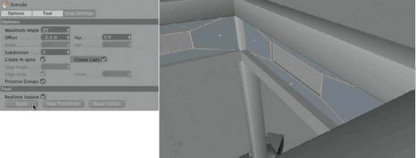
— Figure 2.95: Extruding with activated cap option.

— Figure 2.96: Rounding the windows.
A candle will create the light emanating from the inside of the lantern. Its light will be diffusely scattered by the side paper walls. These paper walls will be modeled from a simple cube. Figure 2.97 shows the highlighted cube. After you adjust its size to the HEIGHT of the inner base polygon of the lantern, convert the cube with the (C) key and DELETE the upper and lower cap in USE POLYGON tool mode. Then switch to USE POINT TOOL mode and adjust the upper corner points by moving them so the object matches the tapered interior of the lantern, as shown in Figure 2.97.
The Decorative Grid of the Lantern
The paper walls are supported by an outer decorative grid made from slim wooden sticks. For their modeling we will first make a copy of the paper wall object and then change to USE edge tool mode. With the kNiFe tool from the StruCture menu add subdivisions as evenly as possible to each of the side faces of the copied object. Figure 2.98 shows, especially on the right side, the desired result of this step.
Then select the edges that are located in the area of the openings and run parallel to the vertical support beams, and select the edge Cut command in the StruCture menu. This allows you to cut in the same way as the kNiFe tool in looP mode. The advantage here is that these cuts are automatically spread out evenly, based on the edge length. As you can see on the left of Figure 2.99 I’ve added a lot of even subdivisions parallel to the floor of the lantern. The SuBdiviSioN value of the edge Cut function should be set to about 25. The goal is to generate a pattern that we can use later to model the decorative grid.

— Figure 2.97: The inner paper hull of the lantern.
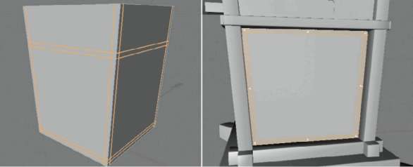
— Figure 2.98: Additional subdivisions of a copy of the paper walls.
Then use the RING SELECTION in the SELECTION menu and select all horizontal subdivisions of the object. The right side of Figure 2.99 shows the completed selection of these edges. These edges also have to be cut with the edge Cut function. Ideally, this will create almost identical square polygons in the area of the four side faces of the lantern.
In USE POLYGON tool mode, use the looP or RING SELECTION in the SELECTION menu to select the geometric pattern, as shown in Figure 2.100. These faces will be extruded to give them a thickness and the remaining faces can then be DELETEd. Therefore, use the INVERT SELECTION command in the SELECTION menu so that all faces that are not part of the decorative grid are selected. With the (Delete) or (Backspace) key these faces can now be DELETEd as long as the mouse cursor is placed over the editor viewport. What remains is the actual pattern of the decorative grid, as shown in Figure 2.101. The paper object used for the cover underneath was set to invisible in order to get a better view of the faces to be edited.
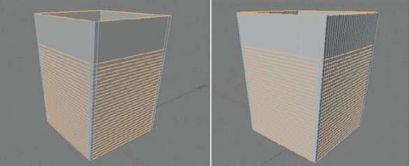
— Figure 2.99: Using the edge cut function to create parallel subdivisions.
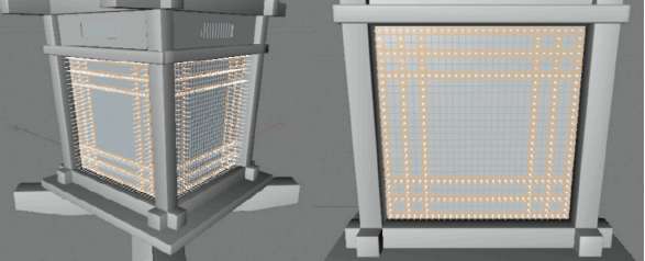
— Figure 2.100: Polygon selection of the desired pattern.
The object of the decorative grid contains a lot of unnecessary points, edges, and polygons. In the first step use FUNCTIONS>oPtiMiZe to DELETE uNUSEd PoiNtS. You can leave all three options activated and close the dialog again with a click on the ok button. Then add a POLYGON reduCtioN object from the OBJECTS>deForMAtioN menu and subordinate it under the decorative grid. Figure 2.101 shows this step and the possible result. The reduCtioN STRENGTH can be set to a very low 1%. The other options of the object should be activated as well. Because all the small polygons lie in one plane they can easily be detected by the POLYGON reduCtioN object and filtered out.
When you have the display of edges activated in the editor viewports you can see the extent of the reduction directly in the editor. To further improve the result, select the decorative grid object and choose FUNCTIONS> CurreNt StAte to OBJECT. This will create a new object in the OBJECT MANAGER that represents the polygon-reduced version of the object. The original, including the subordinated POLYGON reduCtioN object, can now be DELETEd. Use the uNtriANgulAte command in the FUNCTIONS menu and activate only the evAluAte ANgle option. The standard value of 0.1° can be left the same. This function ensures that when two triangles share an edge and the angle between them is smaller than the angle specified in the dialog, they are combined into a quadrangle. In the best possible case, the number of polygons can be cut in half. In this case, the majority of triangles can be removed from the decorative grid. Now there are only triangular faces at the outer frame of the grid, as shown in Figure 2.102. Select all faces of this frame and use the Melt function in the FUNCTIONS menu. The faces are combined into a single n-gon, as shown on the right in Figure 2.102.
After you’ve done this to all four sides of the decorative grid you have to make sure that the normals point uniformly outward. This is indicated by an orange color when the faces are selected. Select all polygons that are aligned differently and use reverSe NorMAlS from the FUNCTIONS menu. This uniform orientation is important for the future shading of these faces but also for the following editing with the eXtrude command because it uses the direction of the normals on the faces as the direction in which to extrude.
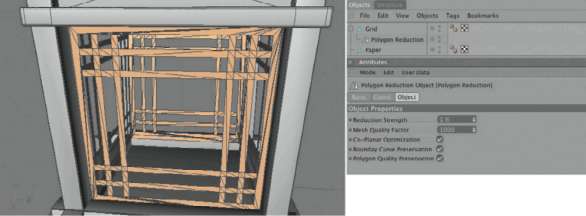
— Figure 2.101: Reduction of the decorative grid.
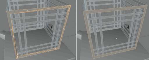
— Figure 2.102: Optimizing the filtered object.
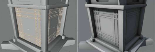
— Figure 2.103: Thickening the decorative grid by extruding with caps option.
Make sure that the CreAte Caps option is activated in the eXtrude tool so a solid object will be generated from the polygons of the decorative grid. Choose the amount and direction of the extrusion in such a way that the selected faces move slightly outward, as can be seen in Figure 2.103.
If you want, you can convert the cube on top at the ridge and refine its shape by moving the lower points at the cube’s ends. This concludes the modeling of the lantern. Figure 2.104 shows an illuminated version of the finished model. In the following section we will work on the materials of the lantern and the preparations for the global illumination through this object.
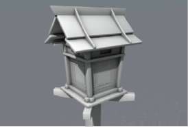
— Figure 2.104: The finished lantern.
The Materials of the Lantern
For the lantern we will use simple materials with intense colors and a slight wood grain. We will start with the material for the roof of the lantern. It is rather dark, so benefits from a bit of reflection and highlight.
THE ROOF MATERIAL OF THE LANTERN
Add a new material in the MATERIAL MANAGER and load the wood shader into the COLOR channel. This shader can be found in the Surface section. We will leave the standard settings, but reduce the MiX Strength of the COLOR channel to 15%. This will reduce the opacity of the wood shader and allow the color in the COLOR channel to show through. For the color we will use a dark and very desaturated blue, as shown in Figure 2.105.
In addition to the COLOR and SPECULAR channels, also activate the REFLECTION and BUMP channels in this material. The REFLECTION, at 15%, is moderate, but strong enough to depict a lacquered surface.
To make the surface look less smooth I loaded the NoiSe shader into the BUMP channel and used a Fire noise that is heavily scaled in the Y direction but has a STRENGTH of only 4%. It is intended to simulate the fine grain of the wood surface. The highlight will be set higher than usual so it looks appropriate for the lacquered surface. In addition, the BliNN shading model set in the ILLUMINATION settings will support the gloss of the material. Since the scene will be lit by global illumination, we should already be thinking about the settings for geNerAte gi and reCeive gi. Because the surface is quite dark and the lantern will be quite small in comparison to the overall scene, we can deactivate the geNerAte gi and save some render time. The receiving properties for global illumination remain activated, however. You can see these settings in Figure 2.106.
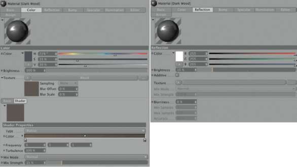
— Figure 2.105: COLOR and reflection of the roof material.
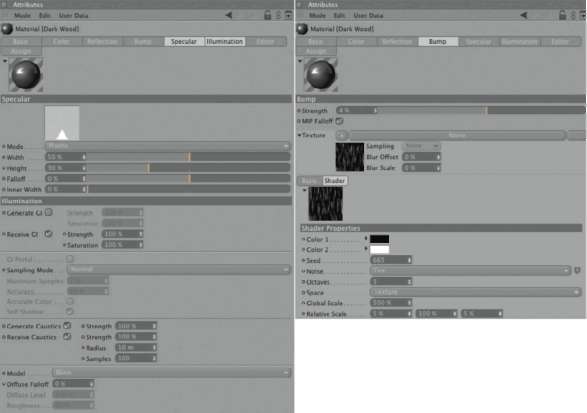
— Figure 2.106: More settings for the roof material.
Apply the material to the SYMMETRY objects that comprise the roof construction of the lantern.
COLORING THE ENDS OF THE CUBES
As a subtle decorative element I’d like to color the open ends of the crossing cubes at the base and under the gable. We will create another material and activate the REFLECTION channel in addition to the standard channels. For COLOR we use a warm but light color. The brightness of the REFLECTION is set again to 15%. Figure 2.107 summarizes these settings. Also, the generation of global illumination has been deactivated.
By using the (C) key, convert the eight cubes located directly under the roof and the ones that form the lower frame at the base plate of the lantern. In USE POLYGON tool mode, select the two end faces of these cubes and save this selection with SELECTION>Set SELECTION. This creates SELECTION tags in the OBJECT MANAGER that don’t need to be renamed because this will be the only saved selection. Pull the newly created light material to one of the cubes in the OBJECT ManAger and enter the name POLYGON SELECTION into the SELECTION field of the TEXTURE tag in the ATTRIBUTE MANAGER. Now this material is only applied to the end faces of this cube. Pull this TEXTURE tag with (Ctrl) drag and drop onto the other seven cubes that already have this polygon selection.
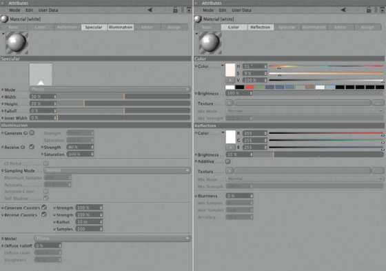
— Figure 2.107: The material for the ends of the wooden sticks.
THE MAIN MATERIAL OF THE LANTERN
The main material used, besides the dark roof material, simulates red lacquered wood. Therefore, we can use a copy of the roof material by using CoPY and PASte in the MATERIAL MANAGER. We will also use the wood shader in the COLOR channel and reduce its opacity to 15%, but this time we will pick a bright red. Then load the AMBieNt oCCluSioN shader from the eFFeCtS group into the diFFuSioN channel of the material. This will result in a sharper contrast between the wood elements of the lantern. We will leave the standard settings for now. Test renderings will show if we will need to adjust the MAXiMuM rAY leNgth. The REFLECTION of 15% is the same as in all the other materials. Figure 2.108 shows all these settings again.
The settings for the BUMP channel remain the same. As Figure 2.109 shows, there are no changes in the other channels, either. That is no surprise since this material is basically the same as the roof material, just with another color. Pull the material onto all the objects WITHOUT a material. If you already created groups, then just apply it to the top object and the objects subordinated underneath will automatically receive the material as well. The cubes with the colored ends receive this material, too. Just make sure that in the OBJECT MANAGER the TEXTURE tag of the light material is to the right and therefore hierarchically above the red wood material. Otherwise, it would be covered, despite the polygon selection.
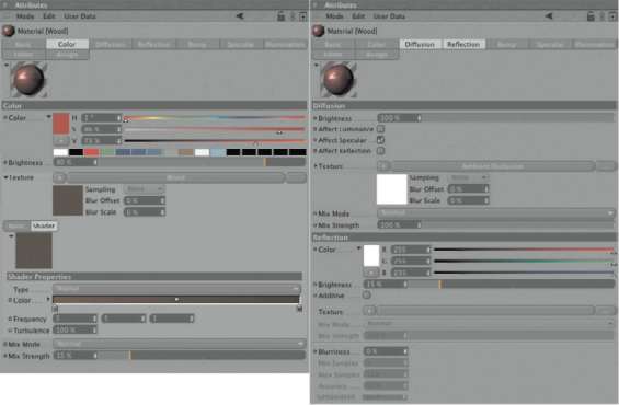
— Figure 2.108: The material for the main body of the lantern.
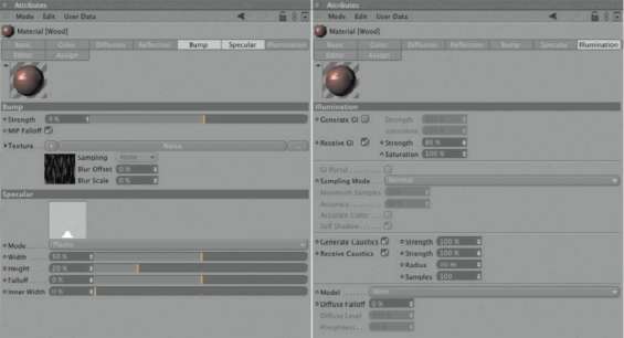
— Figure 2.109: Further settings of the red wood material.
THE PAPER WALL MATERIAL
The texturing of the paper walls of the lantern will be a bit more difficult. They are supposed to look as if a tea light is illuminating them from the inside. We will start again with a new material and deactivate the COLOR channel. The material will be defined primarily by its illuminating properties. Therefore, activate the LUMINANCE channel and load the GRADIENT shader into it. The shader will generate a circular brightness gradient that looks like a translucent wall being lit from behind. It would be even better if the light source were to have a three-dimensional range and able to be moved within the four sides of the PAPer object. Then the flicker of a candle inside the lantern could be simulated.
This effect can be precisely simulated using the 3d SPheriCAl type in the GRADIENT shader. With the RADIUS value and the midpoint coordinate STARt, a spherical space is defined within an object that will be colored with the gradient. The center of this sphere receives color values from the left end of the gradient, and the outer areas are represented by the colors from the other end of the gradient. Depending on the size of your paper wall object, set an appropriate value for the RADIUS. Test renderings are necessary to determine the size and INTENSITY of the light spot. In my case I set the MiX MODE of the LUMINANCE channel to MultiPlY to make it easier to color the illumination and to control the channel’s brightness.
By comparison, the settings for the highlight and the reflective properties are rather traditional, and can be seen in Figure 2.110. It will become interesting on the ILLUMINATION page since, contrary to the other materials, we will activate only the generating properties regarding the global illumination. I’ve entered a relatively large STRENGTH value of 1500%, which was determined from test renderings.
— Figure 2.110: Settings for the material of the paper walls.
— Figure 2.111: Test rendering of the lantern.
As shown in Figure 2.111 overSAMPliNg should be activated as SAMPle MODE because this material will mainly be used to help illuminate the scene. The same figure also shows you the look of the lantern. I combined the two cubes that built the roof, made polygon selections for the faces on the bottom, and applied the red wood material to those selections. This is just a small detail that doesn’t necessarily have to be done.
THE FLICKERING OF THE TEA LIGHT
As previously mentioned, we used the GRADIENT shader in a special 3D mode so a spherical brightness gradient would be calculated. In order to make this appear realistic, the position of the gradient should change during the animation. The Start vector in the dialog of the gradient shader is responsible for this effect. It defines the center of the shader calculation. In order to not have to painstakingly animate this by hand, we will use a nice feature. By using the vibrate tag, CINEMA 4D is able to change objects in cycles or randomly, based on their position, rotation, or size.
Random Vibration with XPresso
We will create a new Null object from the objects menu, right click on it in the object Manager, and assign a vibrate tag from the CINEMA 4D tags list. In the vibrate tag select the enable Position option and set the three Amplitude numbers that define the maximum movement of the candlelight. As you can see in Figure 2.112, I decided to use 40 units each in the X and Z direction and 30 units along the Y axis. This defines the range of movement of the Null object during the random position change. The Frequency controls the speed of the vibration and is measured in vibrations per second. A value of 2 should ensure that the brightness variations don’t appear too hectic.
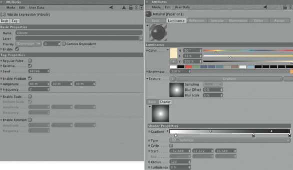
— Figure 2.112: Connecting parameter.
We will now get a random change of position of the Null object when the animation is played. If we transfer these position values to the STARt value of the GRADIENT shader, then the depiction of the candlelight on the paper walls could change realistically. We will achieve this with an expression that can be created with a right click on the Null object and by selecting CINEMA 4D TAGS>XPreSSo.
The XPreSSo editor appears automatically. Pull the Null object from the OBJECT ManAger and the paper material from the MATERIAL MANAGER into the editor. Two function knots or Nodes are created that can be connected to each other. Note that the red side of the node represents the output and the blue side represents the input. First, click on the red area in the title bar of the Null object node and select PoSitioN from the menu. You can find it under COORDINATES>PoSitioN. At the blue input of the material node select the STARt vector from the list of possible inputs. Figure 2.113 shows where to find it. The circular symbols that appear at the sides of the nodes are called Ports. By clicking on one of these ports and pulling with the mouse while holding down the button, you can make connections. Try it and create a connection between the two ports. The local position of the Null object is now transferred to the STARt value of the shader. The XPreSSo editor can now be closed since the desired connections between the objects and parameters were made.
Now when you calculate still images of the lantern at various moments during the animation, the paper material will look different every time. Figure 2.114 shows some test renderings that include global illumination and additional lighting by a SkY object. You can imagine how much more realistic and less static the lantern will look during an animation. We will leave our scene the way it is, though, and combine the parts of the lantern, and also the Null object, with the vibrate tag in a new Null object. You can use the Select All function in the edit menu of the object Manager and then select group objects in the objects menu of the object Manager. Then save the scene.
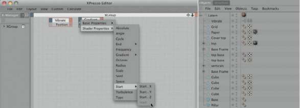
— Figure 2.113: Creating the expression.
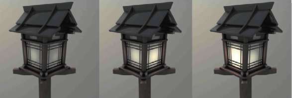
— Figure 2.114: Automatic variations of the illumination with the expression.
Modeling the Stone Stairs
Since our scene depicts a climb up to an old temple, we need to model the missing stairs that will be illuminated from the previously modeled lanterns. These stairs should be made out of roughly chiseled stone blocks. Important here is the variation of the stones so there is no visible repetition in the stairs.
We will start in the top view, the XZ view, by creating several stone profiles from spline curves for one step. I decided to use the AkiMA spline because it can generate rather tight radii and we don’t have to bother with adjusting tangents. You can use another interpolation method if it suits you better. Figure 2.115 shows my complete step and how these splines, subordinated under an EXTRUDE NURBS object, generate a massive object. The length and WIDTH of the step shouldn’t be too short. If the step ends up being too long, the ends can be cut or hidden later. The same is true for the extent of the extrusion. Make the step a bit higher than needed. In order to save some polygons, you only have to create a rounded cap for the top of the step, as shown in Figure 2.115. Make sure that at the Extrude NURBS the hierArChiCAl option is activated so all splines are used. Increase the SuBdiviSioN value to get additional faces at the sides of the stones. We will use them in a moment to further deform the stones.
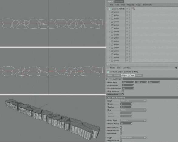
— Figure 2.115: Modeling the stones of one step with extruded splines.
DEFORMING THE STEP INDIVIDUALLY
If necessary, correct the gaps between the stone blocks so there are no large spaces and convert the Extrude NURBS with the (C) key. Because of the hierarchical use of the splines by the Extrude NURBS, not just one POLYGON object is generated, but a group that contains a new Extrude NURBS object for each spline. Select all these Extrude NURBS objects and convert them with the (C) key. The now-converted objects still contain separate objects for the caps and round-ings. After selecting all of these objects, with the use of FUNCTIONS>CONNECT, we will finally get a single POLYGON object. All other groups can be DELETEd. After that, use FUNCTIONS>oPtiMiZe and apply the standard settings by clicking on the ok button. The duplicate points located at the edges of the roundings and caps are then optimized and combined as well. The object is finally ready for the first deformation.
Change to the USE POLYGON tool mode and choose the RECTANGLE SELECTION. In the dialog of the tool in the ATTRIBUTE MANAGER deactivate the option oNlY SeleCt viSiBle eleMeNtS and then pull a selection frame in the side viewport around all the polygons on the side of the stones. Figure 2.116 shows the resulting selection from different views.
In the StruCture menu activate the BruSh tool and set its mode to SMeAr. This represents the behavior of a smearing finger but is applied to geometries instead of paint. Reduce the STRENGTH of the tool to 30% and adjust the RADIUS to the size of the stones so you can work more precisely. When the mouse is over the object, a circle indicates the area the tool is influencing. The brush is automatically restricted to the side faces and leaves the edge rounding and tread area unchanged. Use the brush tool in different viewports to make the sides of the stones look less monotone and straight. Figure 2.117 gives a hint of this process. After deselecting all faces you can use the tool on the treads as well; just be careful with the deformation. The steps shouldn’t turn into a trip hazard, and since the caps of the stones consist of large triangles, too much deformation would generate strange shadows.
— Figure 2.116: Selection of the side faces.
— Figure 2.117: Using the brush for the deformation.
ADDING SEVERAL STEPS
Now it is time to generate several of these steps. Make a copy of the step and place it higher and further back, based on the first step. The stones of the step copy can’t remain the way they are because the obvious repeat of the structure would negatively influence the overall look. Therefore, exchange the positions and orientation of the stone blocks so no two identical stones are placed in the same position within the span of two steps. Since we deal with combined objects within the steps, they can’t simply be selected and moved. We have to switch to USE POLYGON tool mode, select a polygon of the stone to be moved, and then choose SeleCt CONNECTed in the SELECTION menu. All faces of the stone are automatically selected and can then beedited with the MOVE, Rotate, or Sca le tool.

— Figure 2.118: Modeling several stair steps.
Create six steps with different stone arrangements using this method. Figure 2.118 shows how they might look in the end. Note that the steps are overlapping slightly at the base. That way, slivers of light between the objects can be avoided. For each step add a large cube that is spanned across the whole WIDTH of the step. Scale the cube so that the stone blocks enter the cube at the front and tread sides. We will use this cube later to simulate the material between the stones. This could be dirt or cement, for example.
ADDING GRASS
With such rough steps grass will inevitably grow between the stones. We will simulate that grass with the hAir module. If you don’t have this module available you can skip this step. We will start with adjusting small polygons to fit into the spaces between the stones, as shown in Figure 2.119. You could use a Polygon object from objects> Primitive, convert it with the (C) key, and adjust its points. To extend this face you could use the knife tool or extrude tool from the Structure menu. Make several copies of these objects and place them using your own judgment. Then select all of these single objects and combine them with Functions>Connect into a single object.
The Hair Object
At hair>Add hair a so-called hair object is created that automatically creates guides and hairs on the selected object. When only polygons are selected on the object, the growth of the guides is restricted to these polygons. guides are control paths whose tilt and course control the direction and length of the hairs. Many tools of the hAir module exist to manipulate these guideS, such as a virtual brush, comb, and scissors. In our case, though, we don’t have to worry about the guides. In the guideS part of the hAir object dialog, set the leNgth so that hairs are created that are in proportion to the steps. The SEGMENTS value indirectly determines the stiffness of the hairs that can be animated later. The fewer SEGMENTS the guides have, the less they react to the movement of the object on which the hairs grow, or to outer influences like gravitation. A value of 5 is enough so that the grass blades will not be too soft or flexible.

— Figure 2.119: Basic surfaces for the growth of grass between the stones.
— Figure 2.120: Creating hair structures with the hair object.
In the root menu you can determine where the guideS are generated from. In the POLYGON setting the guides are automatically spread across the entire available surface of the applied object. In the hAir section of the dialog, the CouNt value is interesting since it con-trols—as you might already know—the number of hairs generated during rendering. You shouldn’t be bothered by the name Hair. Hairs can take on multiple shapes and can even be instances of objects. Hairs also have SEGMENTS, but they are more like the intermediate points of splines and therefore define the curve of the hairs during rendering. The more SEGMENTS that are used, the better the hair will look-especially longer hair—in the final output. However, this also uses more memory and causes longer render times. In our case we will not use hairs, but instead Polygon objects that the hair object can generate as well. Take a look at the generate section of the hair dialog that is also shown in Figure 2.120. In the type menu you can pick the desired shape of the hair. Flat means the generation of polygon strips, which is exactly what we need to depict blades of grass.
The Hair Material
The shape of the hairs is influenced by the mentioned guides, which influence the physical behavior of the hairs and the general growth direction. An equally large influence on the look of the hair is the hair material. It is responsible for the coloring and a range of shapes that the hair can take on. The material controls the length variations, thickness, curliness, and frizz of the strands of hairs. The use of these properties is activated at the BASIC page of the hAir material, as shown in Figure 2.121. We will need the properties CluMP, FriZZ, and thiCkNeSS to give the growth of the grass enough variety. In the preview of the hAir material you can see immediately the influence an activated option has on the hair growth. Playing with the settings is a must. As you can see in Figure 2.121, I worked with a thiCkNeSS at the root of 2 units. The tiPS are tapered to 0.5 units.
The COLOR and SPECULAR settings have no influence on the display of the grass hairs since we don’t work with standard hairs, but instead the FlAt type. We will take care of that later. The same is true for the ILLUMINATION settings of the hAir material, as shown in Figure 2.122. These parameters are also only of interest with real hairs.
To solve the problem of the coloring, for the moment we can create a new material and set the desired grass color in the COLOR channel. Apply this material to the hAir object. The original hAir material remains as well, for controlling the shape of the hair. Figure 2.122 shows as an example the first step and how a test rendering of the grass clump could look. Now you could increase the CouNt of the grass blades in the hAir object. You should also pull the faces on which the grass is growing lower so they are hidden by the cubes or stones of the steps.
In Figure 2.123 you can see the entire hierarchy of the stairs scene and what settings I applied for the number of grass blades. One thousand blades sounds like a lot, but they are balanced out by the many small clumps and the number of steps.
— Figure 2.121: The settings of the hair material.
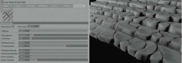
— Figure 2.122: Illumination settings of the hairs.
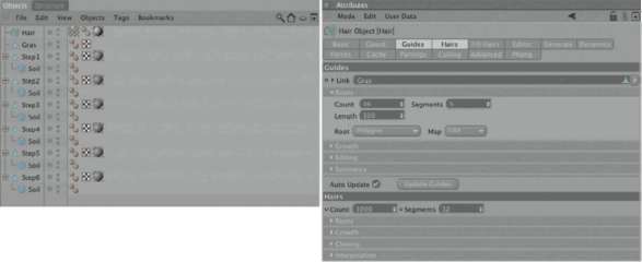
— Figure 2.123: The final settings for the hair object.
The Polygon Hair Shader
We already encountered the problem of the color and highlight properties of the hair material applying only to real hairs, and not to special shapes like a polygon. For these cases you can use the Polygon hair shader, which can be found in the normal list of shaders in the texture area of a material channel as well. Figure 2.124 gives you an idea of the dialog of this shader. I loaded the shader into the COLOR channel of the material we used to color the grass blades. If, like in this case, the option From hair Materials is activated, then the shader automatically uses the color values of the hAir material. This is a good solution if you already defined a gradient in the hAir material.
You could also click on the term COLOR next to the gradient of the hAir material and, after a right click, select the CoPY command. Figure 2.125 shows this step. That way, more complex information, like the color gradient between the shaders, can be exchanged. We will use this for exchanging the already made gradient from the hAir material with the POLYGON hAir shader. Before this is done the FroM hAir MATERIALS option has to be deactivated. In return you gain access to several parameters for controlling the gloss properties.
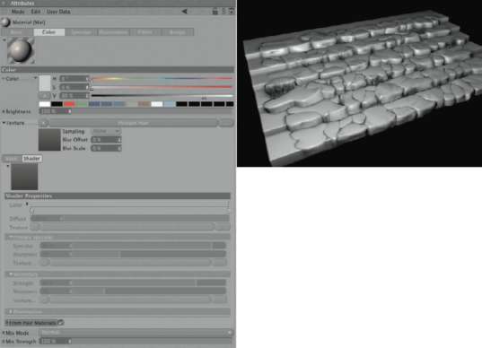
— Figure 2.124: The polygon hair shader.
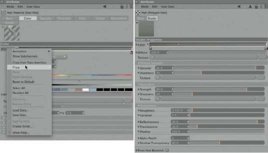
— Figure 2.125: Transferring color values from the hair material to the polygon hair shader.
To give the grass clumps more variety you should move forward, one frame at a time, in the animation. Use the (g) key several times to do so. You should be able to see how the grass blades are bending down because of gravity. If you go too far in the animation, use the (shift)+(g) keys to return to the beginning and the original position of the hairs. When you see a shape you like, use the (C) key to convert the object. You will get a normal POLYGON object that contains all grass blades. The hAir material, including TEXTURE tag, can now be DELETEd since all information about the shape of the grass hairs is implemented in the POLYGON object. The coloring is now completely done by the POLYGON hAir shader. The newly generated hAir tANgeNtS tag behind the converted hairs can also be DELETEd.
The Materials for the Stairs
For texturing the stairs I will again use bitmap textures that I found at www.cgtextures.com in the categories Ground and Stone/ Rock. You can download a certain number of textures every day free of charge or, for a small fee, get an unlimited download. Which texture to use for the materials of the stairs is up to you and isn’t that important for the following steps. The image textures I have used can be found with the scenefiles. Many thanks to Marcel Vijfwin-kel from www.cgtextures.com for letting me use them. The textures are subject to the licensing agreement of www.cgtextures.com, so take a look at the accompanying read-me file.
I like combining the loaded images with the Filter shader in order to make quick color corrections or to change the brightness. Figure 2.126 shows an example of this method in the COLOR channel. This material is meant to be used for the large CuBe objects that run along the entire WIDTH of the steps and extend a bit on the left and right of them as well. These objects are intended to resemble forest soil covered with leaves. Because the image is too bright I also used the diFFuSioN channel. It will darken the material in an irregular manner. The image is used in the BUMP channel as well, but this will not necessarily result in a realistic roughness of the surface. However, this isn’t always the goal. It is often more important that the BUMP and the used image in the COLOR channel are synchronized and that the structures relate to each other. All other settings in the material are pretty common and can be seen in Figure 2.126.

— Figure 2.126: Material settings for the cube objects under the stone blocks of the steps.
We can simply pull the material onto the cube, since it already has UV coordinates applied to it. This would cause a stretching of the material, though, which wouldn’t fit to the structure of the image. Therefore, it is better to select CuBe mapping after applying the material, since it can be easily positioned with the visual aid in the USE TEXTURE AXiS tool mode. Figure 2.127 shows the described settings in the TEXTURE tag and the visual positioning aid in the editor. Use the MOVE and SCAle tools in USE TEXTURE AXiS tool mode to adjust the texture the way you want it on the cube. You should also use a slightly different position for the texture projection on each step to avoid repetition. In the TEXTURE tag, the tile option has to be active as well so the material covers the whole object, despite its small projection area.
THE BASIC MATERIAL OF THE STONES
We will cover the stones with a more complex combination of three different materials that overlay each other with alpha parts. By using this technique, visible repetitions can be avoided. We will start with the basic material of the stones and create a new material. Here, too, I used a texture from www.cgtextures.com that was loaded into a Filter shader in the COLOR channel. I reduced the opacity of this material, using a MiX STRENGTH value of 25%, and left a dark gray in the color settings as the dominant color.
As can be seen in Figure 2.128, I loaded the AMBieNt oCCluSioN shader from the eFFeCtS group into the diFFuSioN channel as well. This will generate more contrast between the stones. The BUMP channel of this material will not use an image this time, but a custom-made pattern instead. We will begin by loading two NoiSe shaders into a diStorter shader. Load the diStorter shader from the eFFeCtS shader group into the BUMP channel and fill the TEXTURE and diStort fields in these shad-ers with NoiSe shaders, as shown in Figure 2.128 on the right.

— Figure 2.127: Applying the floor material.
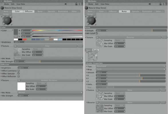
— Figure 2.128: The stone material.
The diStorter uses the brightness variations of the diStortioN texture to distort the shader or image in the TEXTURE channel. You can control the amount of the distortion with the X, Y, and Z sliders as well as with the STRENGTH slider in the upper part of the dialog. There are also several distortion types available. I used the standard settings and slightly increased the distortion, only in the Y direction, to 18%.
You can see the settings I used for the two NoiSe shaders in Figure 2.129. This is just one possibility and is not set in stone. The structures should only be stretched along the Y axis. The remaining settings and the choice of noise pattern were rather random.
The result of this distortion is a completely new pattern that received additional DETAILS and contrasts that didn’t exist in the single shaders. Figure 2.130 shows a large image of the distorted shaders.
The SPECULAR and ILLUMINATION settings are again of a simple nature. The highlight is wide and flat, since the stones are not supposed to be wet or polished. For the shading model I used oreN-NAYAr since it is best suited for rough surfaces. Apply this material to the lowest step and select the CuBe mapping again as the projection method. In USE TEXTURE AXiS tool mode, adjust the size and position of the texture to your liking. Figure 2.131 shows a possible placement of the texture. Use the same principle with the remaining steps. Just remember to use a slight variation of the projection, such as a lateral movement of the projection cube.
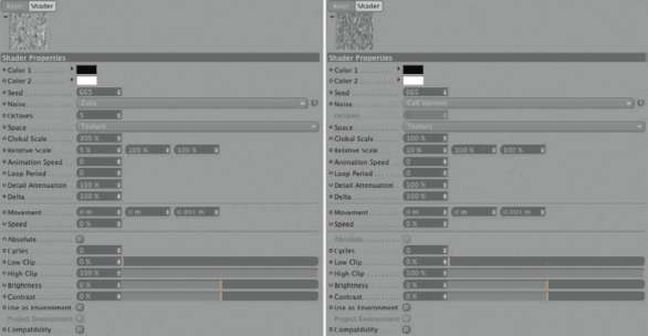
— Figure 2.129: On the left is the texture noise, on the right, the distortion noise.
— Figure 2.130: The distorted noise pattern.
THE SECOND STONE MATERIAL
On top of the basic material that is mainly responsible for the roughness and color of the stones, we will place two additional materials to add some moss and dirt. Create a new material and load a texture into the COLOR channel that portrays a stone covered with moss. Here, too, I used AMBieNt oCCluSioN in the diFFuSioN channel. A more contrast-intense version of the image used in the COLOR channel is utilized in the BUMP channel. By using the AlPhA channel we will ensure that this material doesn’t cover the basic stone completely. I used the Cloud shader from the SurFACe shader group and reduced its gradient to grayscale. The level of the clouds is set to 35%, as shown in Figure 2.132.
The highlight is smaller this time, but we will use oreN-NAYAr here as well. The projection is comparable in its shape and size to the cube under the step. Figure 2.133 shows these settings. Remember to vary the texture projection by moving it, but don’t restrict this to lateral movements only. The variation in Y direction is important, too, so the front edge of the step gets some variations as well.
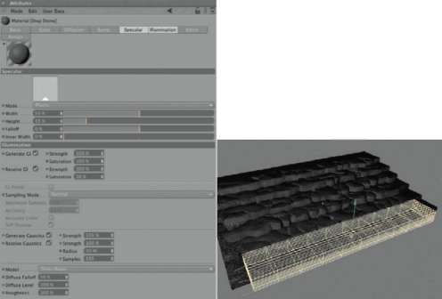
— Figure 2.131: More settings of the stone material.
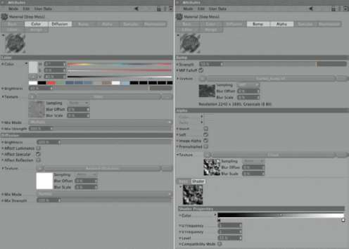
— Figure 2.132: Settings of the first overlaying material.
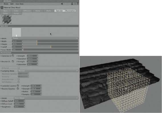
— Figure 2.133: More settings of the moss material.
THE THIRD MATERIAL OF THE STONE STEPS
Again, create a new material. This will be the third material layer on the stones. I used the same image in the COLOR channel that was used with the large cubes under the steps. This should create a connection between the forest soil texture and the stone steps, as well as visually integrate them better. This time, in order to get a material layer that is not so influenced by the gaps between the stones, I did not use AMBieNt oCCluSioN in the diFFuSioN channel. I used the diffusion in this case only to control the general material brightness. The image from the COLOR channel is also used in the BUMP channel so the surfaces don’t look too smooth. Blending with the other two materials on the stones is achieved with the SiMPle turBuleNCe shader in the AlPhA channel. This shader can be found in the SurFACe shader group. Figure 2.134 shows these settings. You can also use the NoiSe shader and pick another suitable pattern. It is only important that there are enough differences from the CloudS shader, which was used in the other material, so that other areas are revealed.
This material also uses oreN-NAYAr as the shading model. It is again applied with a CuBe mapping and can be adjusted randomly to the size and shape of the stone steps. Figure 2.135 shows the current state of the scene. As you can see, all three materials are applied to the steps and are combined into one complex surface with their alpha parts. The only important part here is that the two materials with the alpha parts are positioned to the right of the massive stone material. You should also subordinate all the components of the six steps under a new Null object so the scene is clearly arranged.
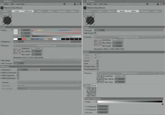
— Figure 2.134: The third of the step materials.
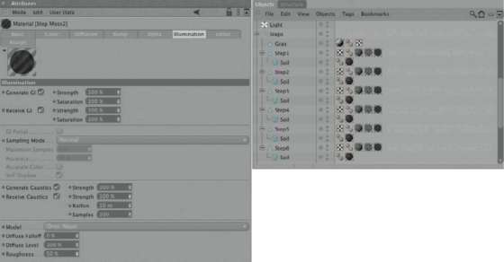
— Figure 2.135: Applying the materials.
— Figure 2.136: Test rendering of the steps.
The first test rendering of the steps looks promising. As you can see in Figure 2.136, the stairs appear to be slightly weathered. In the following steps we will multiply these steps to build longer stairs and integrate the lanterns at the edge of the stairs.
Putting the Scene Together
The main components of the scene are now available as textured models. We can now start to arrange the scene. We will start with the elongation of the stairs by adding copies of the stairs group that we previously modeled. As you can see in Figure 2.137, impressive-looking stairs can be created with just a few copies. Group these repositioned stair copies under a Null object, as shown in Figure 2.137, and add a Bend object from the objects>deformation menu. Adjust its position so that the Y axis runs parallel to the ascending stairs.
The Y length should be about half the length of the stairs. The Bend object also belongs in the group with the copied steps because we will give the stairs a soft curvature as if the path leads us around a mountain.
— Figure 2.137: Extension of the stairs and adding a Bend object.
As you can see in Figure 2.138 we will use the uNliMited mode so the bend affects all the stairs and not just the segment that lies within the BeNd object. For the STRENGTH, I used an angle slightly under 50°, which was randomly chosen. Trust in your own sense for the image composition. It is only important that the first and last step of the stairs not be seen in the image, which will make the stairs appear to be longer.
To be sure that the bend and length of the stairs are correct, we should now determine the final camera position. Set up the perspective editor viewport to achieve a view like the one in Figure 2.139. Then add a CamerA object from OBJECTS>SCENE>CAMerA and activate it by clicking on the symbol behind it in the OBJECT MANAGER. You can also select this camera in the CAMerAS menu of the perspective viewport under the entry SCENE CAMerAS. In any case, this activates the camera and will be used later for the final rendering. In the dialog of the camera in the ATTRIBUTE MANAGER, I decided to use a FoCAl leNgth of 50. It could be necessary to move the camera away a bit from the stairs in order to restore the original distance and viewing angle. Use the navigation icons on the top right in the perspective viewport. After activating the camera, these icons control its position and orientation.
— Figure 2.138: Deformation of all the stairs with a Bend object.
— Figure 2.139: The bent stairs in the final camera perspective.
PLACING THE LANTERNS
The lanterns should be placed on the left and right of the stairs. In order to not create and place the lanterns manually, we will add two spline curves, with any interpolation, that will follow the course of the bent stairs along the left and right sides. Make sure that the distance between the spline and the stairs is constant, but small irregularities are allowed. Figure 2.140 shows the left of the two splines in two views. The HEIGHT of the splines, based on the steps, is not so important. The spline can run slightly below or above them.
— Figure 2.140: Using a spline curve as a positioning aid for the lanterns.
The XRef Object
We don’t simply merge the scene with the lantern. Instead, we will use the Xref object for that purpose. It can be found at objects>Scene. The dialog of this object can be seen in Figure 2.141. The Xref can be compared to an Instance, but it has more possibilities. For example, it can be used to load a scene from another computer in the network. Also, scenes containing animations can be controlled. The Xref can even be used for the handling of materials. The advantage is that you don’t have to work with copies of an object or scene. A change to the original data automatically updates all scenes that have access to this data over Xref. This is especially helpful with larger projects, when several people are working on different components of a scene. You could work and animate, using preliminary versions of the objects, WITHOUT having to update everything manually should a change in the material or on the object occur. In the dialog of the XreF object, use the button with the three dots behind the FILENAMe field to select the CINEMA 4D scene with the lantern. The lantern then appears in the stairs scene. If there are any errors in the XreF scene, then you can open the lantern scene with the edit SCENE button. With animated objects or expressions in the XreF scene, you should click on the tAke ANiMAtioN button after loading the scene. This is the case with our scene, so therefore use the button after loading the lantern file. That way, you can influence the course of the animation, for example, to change the timing so the lanterns don’t flicker all the same way. The buttons reloAd SCENE and reloAd All are only important if the XreF scene isn’t saved on your computer. Otherwise, the XreF object updates itself automatically when changes occur in the referred scene.
— Figure 2.141: The XRef dialog.
With the settings in the Pivot MAtriX, you can change the position and size of the XreF scene. If the lantern appears to be too small or too big in the stairs scene, then you can work with the SiZe values to correct that. In our scene it would be advisable to do this in the original file, since the paper material with its 3D gradient would have to be adjusted to the changed size as well. A scaling of the object wouldn’t automatically scale the shader.
The iNFo section of the XreF shows general information about the loaded scene. You can see the memory use and the number of included objects. Important here is the file setting for the frame rate of animated scenes. It should correspond with the settings in the scene where the XreF object is used. Otherwise, this could cause a slower or faster animation. The lists with the columns XreF o and XreF M show the objects and materials contained in the loaded file. You can pull a material from the XreF M list and apply it directly onto an object in the OBJECT MANAGER.
Select the XreF object and choose FuNC-tioNS>duPliCAte, as shown in Figure 2.142. Set the mode to AloNg SPliNe and pull the spline located on the left of the stairs into the SPliNe field of the duPliCAte dialog. Use the APPLY button to generate the desired number of XreF copies. As long as the duPliCAte tool is active, you can adjust the CoPieS value to control the number of lanterns. I set the value so that at about every second step a lantern is placed. In order to control the orientation of the lanterns better, you can activate the eNABle rotAtioN option and pull the spline from the other side of the stairs into it. It will then be used as a so-called rAil SPliNe for the alignment of one axis of the copies. Figure 2.143 shows the settings in the duPliCAte tool dialog.
— Figure 2.142: Multiplying the XRef lanterns.
— Figure 2.143: Using the rail spline in the duplication.
By selecting the AligN axis, you can align the copies to the second spline. It is only important that the courses of the two splines to the left and right of the stairs are the same. When you are happy with the result, pull the original XreF object into the new group with the XreF copies and then pull the group up or down until the lanterns reach the desired position along the edge of the stairs.
Use the same principle for the other side of the stairs. Create a manual copy of the XreF object and pull it from the group of the other XRefs to the uppermost level in the OBJECT MANAGER. Use the duPliCAte command in the FUNCTIONS menu again for this XreF object. This time the splines just have to be switched. Pull the right spline of the stairs into the SPliNe field and the left spline into the rAil SPliNe field. If necessary, adjust the number of generated copies in the dialog so the ratio of lanterns to the left and right is balanced. Then pull the original XreF object into the Null object group of the right XreF copies and move this group as well, until the position of the lanterns is correct.
To loosen the rigid order of the lanterns, select all XreF objects in the scene with a selection frame in the OBJECT MANAGER. You could also select the uppermost Null object of an XreF group and choose SeleCt ChildreN in the edit menu of the OBJECT ManAger. Then deactivate the Null object of this group again with a (Ctrl) click in the OBJECT MANAGER.
The variation of all these objects will now be achieved with the rANdoMiZe tool from the FUNCTIONS menu, as shown in Figure 2.144. This tool offers several settings for the maximum movement, scale change, and angle variation of the selected objects. I decided to use a maximum of 40 units along the Y direction as the MOVE value and a rotation of 10° around the H axis as the rotAte value. The latter value is entered into the first field since angle vectors in CINEMA 4D are not seen as rotations around the X, Y, and Z axes, but instead as vectors H, B, and P. This should result in a random rotation of the lanterns around their Y axes. The result can be seen on the right in Figure 2.144.
In order to get a more randomized lighting of the lanterns, select the XreF lanterns one by one and vary the SCENE tiMe so that all lanterns are loaded into the scene with a different SCENE tiMe. This will affect our XPresso and Vibrate expression in the original scene of the lanterns and cause different settings for the 3D gradient in the paper material of each lantern. As explained earlier, the tAke ANiMAtioN button has to be pressed for the randomization to take effect. If you have done this already, as described in the first XreF scene, then the XreF duplicates have assumed this information.
ADDING A GREEN HILL
The scene still looks unnatural, and lacks some vegetation. We are outdoors, after all, and I’d like to have the stairs merge, on the left side of the scene, into a mountainside covered with ivy. Add a new CuBe primitive and place it to the left of the stairs. Create a copy of the BeNd object from the stair steps group and subordinate it under the cube. After increasing the SEGMENTS of the cube along the stairs and enlarging the cube in this direction, the result could look like that shown in Figure 2.145. The cube became a wall that runs parallel to the stairs.
— Figure 2.144: The aligned and positioned lanterns.
This rectangular wall profile doesn’t look much like a realistic mountainside yet. Select the CuBe and use FUNCTIONS>CurreNt StAte to OBJECT. The deformation of the BeNd object is then transferred permanently to a POLYGON object copy of the cube. The original CuBe object, including the BeNd deformer, can then be DELETEd. Use the MOVE tool or the BruSh tool, which we previously used with the steps, to reshape the cube so it looks more like a mountain, at least through the view of the camera. Figure 2.146 shows different views of this object. You can also see that I changed the structure of the cube. This is necessary since we will edit this object in another program that can only handle triangular faces. Therefore, all quadrangles have to be exchanged with two triangles. Don’t worry, because there is the triangulate tool in the Functions menu that will do the job for us.
— Figure 2.145: Using a bent cube as the scene border.
— Figure 2.146: Converting and triangulating the cube.
The deformed and triangulated cube now has to be saved as an OBJ file. The best way to do this is to use the Copy command in the edit menu of the object Manager and select FILE>New in the CINEMA 4D layout. Then, using Paste in the edit menu, put the object into a new, empty scene. Now you can save the object with FILE>export>wavefront as an OBJ file.
The Ivy Generator of Thomas Luft
The modeling of organic shapes like plants and trees can take a lot of time. There are many special solutions for this kind of object. You can use already-modeled trees and bushes, or so-called plug-ins, or independent programs specialize in the generation of such 3D objects. A very useful program in this category is the ivY geNerAtor by Thomas Luft. This program enables you to grow ivy on any geometry with the push of a button. Many parameters for adjusting the size and density of the leaves are available and make this free program indispensable. The current versions for Linux, Windows, and MacOS X can be found at http://graphics.uni-konstanz.de/∼luft/ivy_generator/. The software works correctly only with triangles. In addition, all polygon normals should point outward. This is automatically the case with our converted cube. The objects should have a simple geometry so the calculations of the ivY geNerAtor can be completed faster. The program has to do several collision calculations of the plants, thus the simpler the geometries are, the more precise these calculations will be.
With the program open, use the iMPort oBj + Mtl button to load our deformed cube geometry. You can find this button in the SCENE area of the program, as shown in Figure 2.147. Use the left mouse button to rotate the 3D view. By holding the (Shift) key at the same time, you can rotate around the center of the viewport. The left mouse button can be used in combination with the (Ctrl) key to move the view. Additional information about the use of the program and the functions of its parameter can be found in the read-me file accompanying the software.
— Figure 2.147: The imported cube in the Ivy Generator.
The starting point for the growth of the ivy tendril is set with a double click on the loaded geometry in the 3D view of the ivY geNerAtor. You can see the point marked in green in Figure 2.148. With a click on the growth button in the growiNg part of the dialog, the growth of the tendrils is started. They are calculated based on the settings on the growiNg page. This is not yet the actual geometry of the tendrils, but the growth paths of the tendrils. When the desired complexity and expansion of the plant is reached, click on the grow button again to stop the calculation. Figure 2.149 shows a possible result. If you don’t like your result, just change the parameters and double click on the model again to create a new starting point for the calculation, then click again on the grow button.
When you have achieved a course of the tendrils you like, change to the Birth page of the dialog and define the profile of the tendrils and the size and the density of the leaves. Keep in mind that we might need to use several ivy plants in the scene, so don’t overdo it with the density of the leaves. Also, try to get the size of the leaves to be in proportion with the size of the mountainside, which can be used to estimate the scale in our scene.
You can experiment with the settings WITHOUT having to recalculate the tendrils every time. A click on the Birth button uses the existing tendrils for the changed Birth settings. Figure 2.150 shows a possible result for the virtual ivy.
The only thing left to do here is use the eXPort oBj + Mtl button in the SCENE part of the dialog to save the 3D geometry of the ivy. Figure 2.151 shows this final step. The OBJ format can be opened again in CINEMA 4D WITHOUT any problems. If you like, you can generate and save many different ivy plants for our mountainside. Then later you will have a choice of several different plants and can pick the best one.
— Figure 2.148: Settings for the growth of the ivy.
— Figure 2.149: Finished growth of the ivy tendrils.
— Figure 2.150: Settings for the number and size of the leaves and tendrils.
— Figure 2.151: Exporting the 3D geometry.
CREATING THE ENVIRONMENT OF THE SCENE
Use FILE>Merge to load the OBJ file with the ivy into the stairs scene of CINEMA 4D. The loaded image should be the right size and at the right location in the scene. If that is not the case, check the settings at edit> PreFereNCeS>iMPort/eXPort for loading and saving Wavefront files. Both values should be identical. If necessary, scale the new objects manually and move them to the correct position.
The ivy should already contain POLYGON selections, which will make it easier to apply materials to the leaves and tendrils. You can create your own leaf texture or use the leaf textures offered at http://graphics.uni-konstanz.de/∼luft/ivy_generator/. The creator of these textures is Tim Ellis. These materials contain color bitmaps, NorMAl, and AlPhA maps. Figure 2.152 shows how you can use these images in the leaf material.
Texturing the Ivy
The color texture belongs of course in the COLOR channel, where the coloring of the leaf can be adjusted with the Filter shader. The NorMAl image goes into the NorMAl channel and will simulate fine leaf structures. The alpha image will be loaded into the AlPhA channel of the material. Make sure that the INVERT option is checked, since the material system of CINEMA 4D works with the opposite brightness of the texture being used.
Because the leaves are very small in comparison to the overall scene, the geNerAte gi option on the ILLUMINATION page can be deactivated to save some render time. As shown in Figure 2.153, we will leave the rest of the standard settings as is.
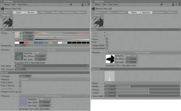
— Figure 2.152: Material settings for the ivy leaf.
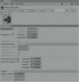
— Figure 2.153: Illumination settings of the leaf material.
The material of the tendrils is created in the same way. These textures can be found at the aforementioned website as well. Only the AlPhA channel is not needed.
As you can see in the series of images in Figure 2.154, ivy can be used not only for a floor covering but also for the simulation of bushes and trees when they are far enough from the camera. In our example, I simply created copies of the textured ivY object and rotated them by 90° so the tendrils reach toward the sky, resulting in a simple tree. These ivy copies are placed to the right side of the stairs and moved backward, based on the camera’s view.
We shouldn’t forget the MouNtAiNSide object. We will use the same forest soil material that was applied to the large cubes under the stairs. Since we have different proportions here, the texture should be repeated several times on the surface. As you can see in Figure 2.155, you have to increase the tile X and tile Y values evenly until the right texture size on the object is reached. We have to use the uvw MAPPiNg in the PROJECTION settings because the cube was deformed by the Bend object. CuBe mapping could cause, in extreme cases, a distortion of the texture.
— Figure 2.154: Step-by-step vegetating of the scene with copies of the ivy object.
The Sky in the Scene
I would like to use a photo as the sky, one that I created by stitching together a series of shots of the evening sky. This panorama is going to illuminate the scene as well as be a visible background. The corresponding image can be seen in Figure 2.156.
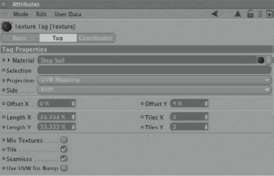
— Figure 2.155: Texture tag of the mountain side.
First, create a PLANE object from OBJECTS> PriMitive. Then create a new material and load the sky image into the LUMINANCE channel. All other channels can be left deactivated. The calculation of highlights in the sky would look funny. In the LUMINANCE channel you can see the resolution of the bitmap after it is loaded. Transfer these values to the size of the PLANE object. In our case, this means a WIDTH of 5896 and a HEIGHT of 1195 units. This ensures that the texture will be displayed WITHOUT distortion on the object and that the ratio is correct. The plane can be adjusted to the proportion of our scene by scaling it evenly. In the ILLUMINATION settings, change the STRENGTH value for geNerAte gi to 500%, since the image is quite dark and we still want some illuminative effect in the scene. reCeive gi can be deactivated because the sky doesn’t have to be lit. We will use overSAMPliNg as the sampling mode since it calculates quickly, although not as precisely as other methods in this menu.
As shown in Figure 2.157, pull the material onto the SkY plane and place it in the scene so the desired section of the sky texture is captured by the camera. I decided to use the clouds that are lit from behind by the setting sun. Don’t worry if the plane doesn’t cover the entire background of the scene. As you can see on the left of Figure 2.157, the right side can remain open. This area will simply be calculated in black. Since we will render an evening scene, it shouldn’t affect the overall mood. You should now subordinate a BeNd object under the PLANE object and rotate the BeNd object so its Y axis points to the left and right side of the scene. With this BeNd object you can bend the plane, as shown on the right of Figure 2.157. This is an advantage for the global illumination of this plane, since the light will enter the scene in a natural way from different directions.
As can be seen in Figure 2.158, I applied a COMPOSITING tag to the SkY plane with deactivated CASt ShAdowS and reCeive ShAdowS options. If we use light sources with cast shadows later, this will prevent any interaction of the sky with these shadows. The COMPOSITING tag is created with a right click on the SkY object and the selection of CINEMA 4D TAGS>COMPOSITING.
Since the global illumination works best within a limited area, we will add a SPhere primitive and scale it so the camera and the stairs, including the ivy objects, fit within it. Then convert this sphere with the (C) key to a POLYGON object and change to USE POINT TOOL mode. Select and DELETE some points so that a shape like the one shown in Figure 2.159 is created. This object is now used as a reflector for the light beams that will be sent into the scene by the sky. Because of this geometry the light beams aren’t lost, but are, when the diffuse depth is set large enough, reflected to the stairs and the lanterns.

— Figure 2.156: The sky panorama.
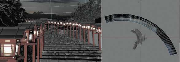
— Figure 2.157: Placing the Sky object.
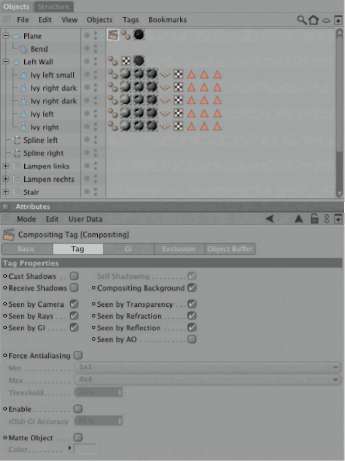
— Figure 2.158: Compositing tag of the sky plane.

— Figure 2.159: Adding a reflector for the scattering.
Simulating the Sun
A general problem of global illumination is that it is often difficult to generate highlights. This can only be prevented by using high-resolution HDR images. In our case, we receive the illumination exclusively from a rather dark 24-bit image and some illuminating faces of the lanterns. Therefore, I added a normal PoiNt light to the scene and placed it where the stairs leave the image on the top left. The right side of Figure 2.160 shows a view of the scene from the position of the new light source, to give you a better idea of its location. I will give the light an intense orange color, 100% INTENSITY, and no shadow. I also deactivated the options for diFFUSE and gi ILLUMINATION. Only the SPECULAR option stays active so this property can be added to the scene. As you can see in Figure 2.160 I also subordinated a diSC primitive, under the light source, which also receives a material with an intense orange color. The disc should be oriented with its surface facing the scene and should have a COMPOSITING tag with deactivated ShAdow options applied to it. I also activated the COMPOSITING BACkgrouNd option so no shading appears on the disc. The disc has to be positioned slightly behind the light source so it doesn’t cover the light. The purpose of this object is to act as the reflection of the sun onto our reflective objects. The lacquered materials of the lanterns will benefit nicely from that.
Defning the Depth of Field
Scenes like this can benefit from a slightly blurry background. It gives the image more realism and depth when this effect is used in a subtle way. Select the CAMerA object in our scene and take a look at the dePth section of the dialog in the ATTRIBUTE MANAGER. The tArget diStANCe defines the area in front of the camera that is supposed to be sharp. With reAr Blur active, the STARt and eNd values define the area behind the tArget diStANCe where the blurriness is slowly increased. With the distance tArget diStANCe + eNd, the blurriness is at its maximum. Since all this is a bit abstract, there are additional handlers and guides for this effect in the editor viewports. In Figure 2.161 they are pointed out by arrows. You can see that the image remains sharp up to the first step and then becomes blurry toward the end of the stairs.
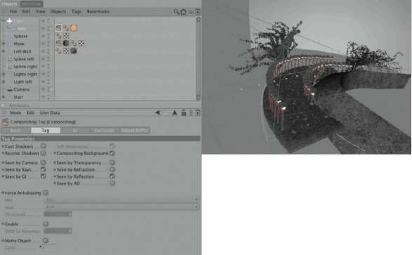
— Figure 2.160: Simulating a sun.
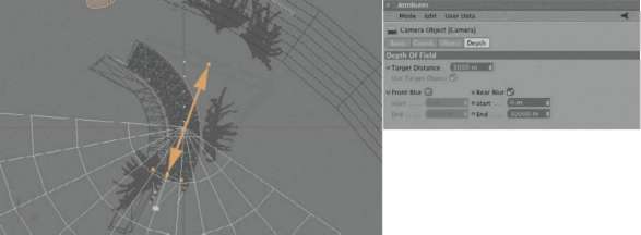
— Figure 2.161: Setting the depth of field of the camera.
Rendering and Saving the Scene
Now we get to the RENDER SettiNgS. Generally, it is beneficial for the postproduction process if you save the images with multiple passes. Only then can fast corrections be made to the shadows, the sharpness of reflections, the depth of field, or the INTENSITY of the global illumination WITHOUT having to render the image all over again. Therefore, I will add through the Multi-Pass button the channels BleNd ChANNel, SPECULAR, gloBAl ILLUMINATION, REFLECTION, and dePth. As you can see in Figure 2.162, I activated in BleNd ChANNel all image properties that aren’t covered by the other Multi-Passes. That way, we can mix components with the image and adjust them to our liking.
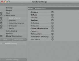
— Figure 2.162: The render settings of the scene.
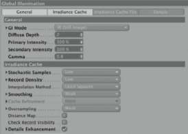
— Figure 2.163: Settings for global illumination.
In the SAve settings, define the file path and the file format. The Photoshop or BodyPaint 3D format is generally used since they can handle multiple layers and apply the correct layer settings to put the image together again from single passes.
THE GLOBAL ILLUMINATION SETTINGS
As for the global illumination, I decided to use the ir mode since our sky doesn’t enclose the entire scene and the SkY SAMPler wouldn’t be precise enough. A diffuse depth of 2 should be sufficient to create enough diffuse samples. I increased the PriMArY iNteNSitY to 300% so the scene doesn’t end up too dark. This is a result of my test renderings. The gAMMA value, on the other hand, was lowered to less than 1 so I could achieve more image contrast. Otherwise, my stairs would have become too bright and would not have enough contrast.
As you can see in Figure 2.163, I used generally low and weak settings for the GI. This helps to reduce the render time and gives us good results with our scene. As a counterbalance, though, I activated the DETAILS enhancement option so I don’t lose too many DETAILS of the image.
After some color corrections and blurring of the depth of field, the result looks like that in Figure 2.164. The lighting mood is of course heavily influenced by the environment. You could remove the fake sun, the reflector sphere, and the bent sky plane again and use the Sky object exclusively. Figure 2.165 shows a possible result with the exclusive use of the Sky object for the illumination and depiction of the sky.
Using the Sky Object for the Lighting
In daytime situations you have to remember to modify the material for the illuminating paper of the lanterns. I deactivated the luminance channel completely and activated the COLOR channel again. Also, the Sample MODE in the illumination settings has to be set back to Normal.
— Figure 2.164: The finished evening mood image.
— Figure 2.165: Illumination by the Sky object.
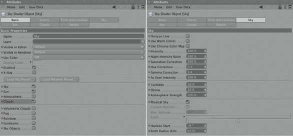
— Figure 2.166: Settings of the Sky object.
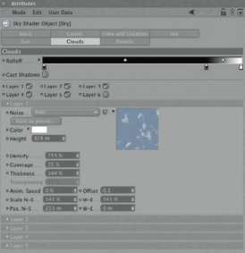
— Figure 2.167: The settings for the clouds.
In the SkY object itself, simply set the time and watch how the position of the sun and the illumination change in the editor. To have the sky consist of something other than a gradient, you can activate the CloudS option in the BASIC settings, as shown in Figure 2.166.
It is important for our scene that the horizon, the spot where the cloud cover ends, isn’t visible in the image. Otherwise, it would be obvious that we don’t have a floor in our scene. Therefore, we need to pretend to be at a higher elevation, such as on top of a mountain, and move the value for the horiZoN STARt in the SkY section slightly into the negative range. Figure 2.166 shows this value on the right side.
The shape and density of the clouds themselves are defined in the Cloud section of the SkY object. There are six layers that can be filled with different NoiSe patterns. These patterns should look familiar to you since they are also used in the NoiSe shader. The individual layers can be assigned to separate HEIGHTs and moved separately during an animation to simulate wind. As you can see in Figure 2.167, I kept the standard settings for a sparse cloud cover, indicating nice weather, and changed the gradient for the rolloFF instead. This can be found in the top of the dialog. This gradient ensures that the noise structure of the clouds is turned off close to the horizon and is replaced by the color of the clouds. The transition to the horizon disappears and is replaced by a sort of colored fog, which looks more natural. When the brightness is moved closer to the left side of the gradient, this blending starts earlier, at a greater distance from the horizon. I like that look and used it to end the clouds earlier and blend them into a fog. You can see, in Figure 2.168, another lighting mood that was calculated with an even lower sunset by the SkY object.
— Figure 2.168: Alternative lighting mood.
