4 Character Animation
Character animation is one of the most interesting, but also the most challenging, projects that can be realized with CINEMA 4D. The MoCCA module of CINEMA 4D is used almost exclusively for this purpose. In this chapter, with the help of an example, you will learn about all the important functions of CINEMA 4D and MOCCA used to model a character, to edit the UV coordinates with BodyPaint 3D and apply a texture to it, to prepare the character for animation, and finally to animate it. At the conclusion there will be a short excursion into the WORLD of game development. Using the Unity 3D software, we will explore the possibility of exporting the developed character to a game engine and to interactively control it there.
The Sketch Phase
Before the first polygon is set we should have at least a rough idea of how the object to be modeled should look. This is especially true for characters. In the case of realistic characters, photos of humans and animals can be used as templates to achieve the right proportions. Since the whole process up to the finished animation will be demonstrated in this chapter, we will not spend much time with the modeling of a complex character, but instead create a more simply constructed creature.
Sketching with Doodle
Thanks to the new doodle function, we can do the necessary sketching directly in CINEMA 4D. Even the so-called blocking, the evaluation of an animation using key poses, is possible. Open the brush tool in the tools menus of CINEMA 4D under doodle. In the ATTRIBUTE MANAGER there are some basic settings, as shown in Figure 4.1, such as the COLOR, opacity, and Size of the brush. When you plan an animation with several Doodle images, activate the Auto-Add Frames option. This will create a new sketch whenever you move to another position in the timeline and use the doodle brush. Otherwise, the new brush strokes are added to the existing sketch. If you make a mistake, you can use the doodle eraser, which can be found in the same menu as the brush.
With the doodle brush active, I start to sketch the desired shape of my character in the side viewport. My idea of the character is a mix between a frog and a troll and should be easy enough to model. Figure 4.2 shows my finished sketch. We will adjust the modeling to this sketch in the following steps. Doodle is automatically placed in the foreground of the viewport. If this distracts you during modeling, deactivate the doodle object, which was automatically created when the Doodle brush was used, in the OBJECT MANAGER. Simply click on the green checkmark behind this object in the OBJECT MANAGER to turn it off.
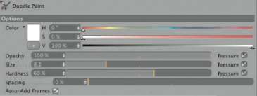
— Figure 4.1: Using the Doodle brush to create sketches in CINEMA 4D.
A quick look at the tiMeliNe, which can be opened in the wiNdow menu of CINEMA 4D, shows that something happened here as well. The doodle object sets the keyframes for the created sketches when the Auto-Add FRAMES option is active. Otherwise, you can set a manual keyframe anytime with toolS> doodle>Add doodle FRAME and fill it with a new sketch directly in the editor. In the same menu you will find commands for duplicating, erasing, or deleting a Doodle sketch.
Clicking on the keyframe will open a small preview in the ATTRIBUTE MANAGER, with an arrow button next to it, as you can see in Figure 4.3. This arrow button can be used to navigate to other drawn Doodle sketches.
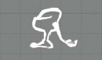
— Figure 4.2: A sketch of the character to be modeled in the side viewport.
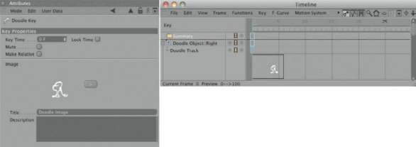
— Figure 4.3: Keyframes with Doodle.
The Modeling of the Character
The modeling of the sketched character doesn’t require many steps. The basic shape of the body can be shaped using a sphere, while arms and legs can be shaped with the extrusion of faces. We will start with a new SPhere primitive and adjust its size and position to the sketch in the side viewport. The polygonal structure of the sphere can be influenced in the TYPE menu in the ATTRIBUTE MANAGER. In the heXAhedroN setting only quadrangles are used. This will be helpful later when the shape is smoothed by a HYPERNURBS. Figure 4.4 shows these settings.
To further adjust the shape of the sphere to the sketch, convert it with the (C) key and then activate the BruSh tool in the StruCture menu. The brush has several settings available in the MODE menu in the ATTRIBUTE MANAGER to define its function. These range from painting and blurring of vertex maps to the distortion and smoothing of surfaces. In SMeAr mode, the brush works in a manner similar to the MAgNet tool, found in the StruCture menu as well, and provides a simple way of deforming the object.
In USE POINT TOOL mode, edit the sphere so it conforms more to the contours of the Doodle sketch and looks pear-shaped in the front viewport. Figure 4.5 shows a possible result.
Modeling the Mouth
To create a mouth, we need to open the structure in the front half of the sphere. We will use the kNiFe tool in the StruCture menu and set it to looP mode. Make sure that the creation of n-gons is deactivated. First, make a horizontal cut where the mouth line was drawn in the sketch. The left image of Figure 4.6 shows this highlighted cut. After that, switch to USE POLYGON tool mode and select the polygons above this cut, which are supposed to be the upper lip. This selection is shown in the middle image of the figure. Then use the diSCONNECT command in the FUNCTIONS menu, which disconnects the selected faces from the surface. These polygons now have their own new corner points. Don’t confuse this with the CloNe command in the same menu. The CloNe command copies the selected faces into a new object and leaves the original object unchanged.
In order to partially reattach the disconnected polygons to the faces of the sphere, change back to USE POINT TOOL mode and select all points along the upper edge of the disconnected faces. The points of the sphere as well as the points of the disconnected faces have to be selected, so enable the selection of hidden elements as well. The desired selection is shown on the left of Figure 4.7.
Then select the oPtiMiZe command in the FUNCTIONS menu and activate all its options. In our case, only the PoiNtS option in connection with the tolerANCe value is important. It ensures that points within the specified distance from each other are combined into one point. Because of the previous selection, the combination of points is limited to those at the upper edge of the disconnected faces.

— Figure 4.4: A hexahedron sphere primitive as the start object for the modeling.
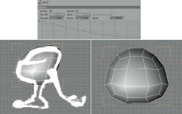
— Figure 4.5: Shaping the sphere with the brush.
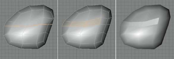
— Figure 4.6: Creating the opening for the mouth.
After the optimization, expand the still selected points with SELECTION>grow SELECTION. This automatically selects the points at the lower edge of the disconnected polygons, too, but not the points of the sphere located at the same position. Deselect all other points while holding the (Ctrl) key. Now only the points at the lower edge of the disconnected faces should be active. Shrink these points with the SCAle tool, as shown on the right in Figure 4.7. A gap is created where the upper and lower jaw meet.
MAKING POLYGONS TEMPORARILY INVISIBLE
During modeling you can quickly get lost within DETAILS, especially when a model becomes more complex. Sometimes the view is simply obstructed. This problem can be solved by temporarily turning off some of the polygons. In our case I want to further model the inside of the lower jaw, but because of the closed sphere shape this is made difficult. Therefore, we will select all faces on the upper part of the head as shown on the left in Figure 4.8, then use hide SeleCted in the SELECTION menu. In the same menu there are also commands for making the elements visible again or to invert the visibility, meaning that the faces will not get lost.
In the now open lower bowl shape, select the edges marked on the right in Figure 4.8 in USE edge tool mode. These are the edges leading to the corners of the character’s mouth.
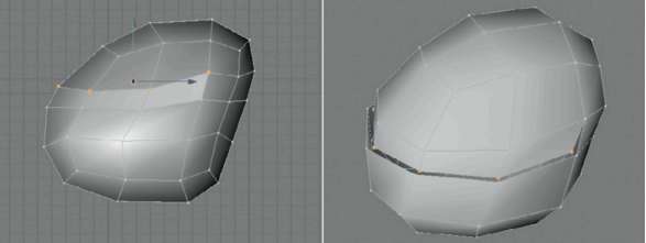
— Figure 4.7: Merging the upper row of points.
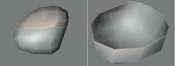
— Figure 4.8: Making faces invisible to simplify the work on the inside.
The eXtrude tool in the toolS menu can extrude not only polygons but also edges. The selected edges are duplicated and create new faces with the oFFSet movement, as shown in Figure 4.9. In order to have these faces placed perpendicular to the outer polygons, we will use an edge ANgle of 90°. Either combine this with a negative oFFSet value or use a positive oFFSet with a negative edge ANgle value. The goal is to create faces on the inside of the head, as shown on the right of Figure 4.9. Now make all polygons of the head visible again by using SELECTION>uNhide All.
SHAPING THE CORNER OF THE MOUTH
With the future smoothing of the Hyper-NURBS in mind, we will create the connecting faces in the corner of the mouth of the character. There, the faces of the upper and lower lips should blend into each other as softly as possible. The first step is the manual creation of a quadrangular polygon, as shown on the left part of Figure 4.10. Use the CreAte POLYGON tool of the StruCture menu and click in USE POINT TOOL mode on the four points that form the corner of the mouth, in consecutive order. Double click on the last point to create the face. Repeat this at the other mouth corner. Then use the new points on the lower lip to reshape it, as shown in the left part of Figure 4.10.
THE ORAL CAVITY
Turn off the upper faces of the head again with hide SeleCted. Then use the eXtrude tool at the still-active edge selection of the lower lip to create another row of polygons, as shown on the left in Figure 4.11. This time the edge angle is smaller than 90°. The new faces are supposed to run, slightly tilted, in the direction of the lower half of the sphere. The CreAte POLYGON tool in the StruCture menu will help you to close the gap between the new polygons. As you can see in the middle of Figure 4.11, four quadrangles are sufficient for that. These faces can then be compressed along the X axis. The temporary subordination of the model under a Hyper-NURBS shows the effect. The lower jaw is supposed to have a distinctive edge along the lips, but then should swing down in a soft bulge.
THE UPPER JAW
The upper oral cavity is shaped using the same principle. We will make some space first by making all faces visible again with SELECTION>uNhide All. Make sure that you are in USE POLYGON tool mode again, since points and edges can also be turned off.
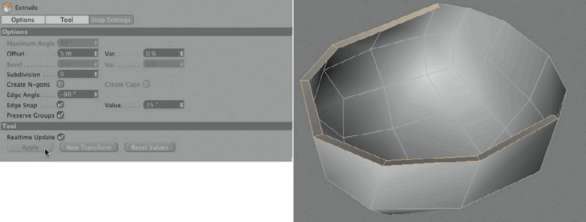
— Figure 4.9: Extruding edges.
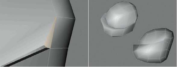
— Figure 4.10: Adding a connecting polygon at the mouth corner.
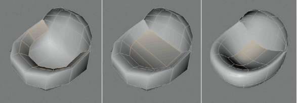
— Figure 4.11: Closing and shaping the lower oral cavity.
Then turn off the faces of the lower half of the head the same way as before. This could look like the left side of Figure 4.12. Again, switch to USE edge tool mode and select the edges of the open edge, but this time at the upper lip. Use the eXtrude command to create a row of polygons perpendicular to the outer faces on the inside of the head, as shown on the right of Figure 4.12.
Stitching Points
In the area of the corner of the mouth we will get a point, by way of this extrusion, that has no connection to the faces of the lower lip. We will therefore combine this point with the corresponding point of the lower lip. The points in question are highlighted in the middle of Figure 4.13. For a better understanding, the image on the left shows where the previously extruded faces of the upper lip, in the area of the inner mouth corner, are still selected.
Because the lower of the two points is supposed to remain at its current location, we will use the StitCh ANd Sew function in the StruCture menu. This allows us, by holding down the mouse button, to pull a connecting line between the points that should be combined. The arrows on the right of Figure 4.13 indicate this. Because the open point at the inner edge of the upper lip is to be moved, it has to be clicked on first and, while holding the mouse button, pulled to the lower point so it snaps to this point. Make sure when you use the StitCh ANd Sew tool that either no points of the object, or just the two points that are supposed to be combined, are selected. This function is limited to only these selected elements.
The following steps are again identical to the ones used at the lower jaw. Extend the faces at the open edge of the inside of the upper lip with an extrusion, so they move further toward the inside of the head and upward. Then manually close the gap in between using four quadrangles, with the help of the CreAte POLYGON function in the Structure menu. The right part of Figure 4.14 highlights the previously extruded faces and the closing faces on the inside. The left part of the figure shows how the corner of the mouth is supposed to look with activated HYPERNURBS smoothing.
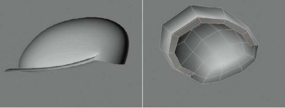
— Figure 4.12: Turning off the lower half of the head and extruding the lower lip.
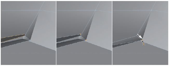
— Figure 4.13: Combining the new faces with the corner of the mouth.
Closing Holes Automatically
Make all polygons visible again by using unhide All in the Selection menu, and then turn some faces off again at the back of the head with hide Selected. You should see an opening there, as shown on the left in Figure 4.15. It is the result of the missing connection in the back of the head between the upper gum and the lower mouth cavity. Such holes, openings bordered on all sides, can be automatically closed. Select CloSe POLYGON hole in the StruCture menu and place the mouse pointer over a section of the open edge. A highlighted preview face appears that represents a preview of the closing of the hole. A mouse click then actually generates this face and closes the hole, as can be seen on the right of Figure 4.15. This almost completes the modeling of the head. In USE POLYGON tool mode, you can turn on all faces again.
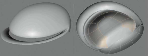
— Figure 4.14: Closing the upper mouth cavity.
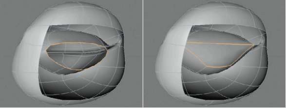
— Figure 4.15: Combining and closing the mouth cavity.
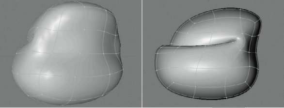
— Figure 4.16: Final shaping of the head.
Take some time and take a long look at the head with activated HYPERNURBS smoothing. If you didn’t use a HYPERNURBS yet, add one from the objects menu under NURBS, and subordinate the head model under it in the object Manager. The function of the HYPERNURBS can be deactivated anytime by clicking away the green checkmark behind it in the object Manager. A possible result can be seen in Figure 4.16. Make sure that the lips are placed on top of each other and that there is no visible gap.
Modeling the Legs
The modeling of the legs can be achieved by just using the extrude tool. In use Polygon tool mode start with a selection of the two faces at the underside of the head where the legs are supposed to be developed. The faces and the first extrusion of these faces are shown in Figure 4.17.
Since we need more subdivisions, especially in the area of the groin to improve the flexibility during animation, we will use a little trick. MOVE outward the inside points created by the extrusion of the legs, as the arrows on the left side of Figure 4.18 indicate. The face previously located on the inside of the legs then turns toward the floor and can be extruded, as shown on the right side of Figure 4.19.
EXTRUDING THE FEET
Extrude these faces another two times downward until the desired leg length is reached. Widen the last two SEGMENTS by moving the points, following the example shown on the left of Figure 4.19. This takes care of the base of the feet as well. Because of the needed clarity in the figures, the Doodle sketch is often turned off. You should keep it visible, though, and compare it with your model, since it gives you an indication of the length of the legs, the position of the knees, and the size of the feet.
The two faces in front and back at the lower leg base are then extruded individually to build the basic shape of the feet. The back face is extruded in one step to form the heel, and the front face is extended in two steps, first to the base of the toes and then to the tip of the toes.
Shaping the Toes
In order to keep the modeling effort to a minimum, and in keeping with the simple nature of the character, I gave the little guy a big toe and a combined shape for the remaining toes. The big toe can be formed from the frontal polygon at the tip of the foot. Just shrink this face along the WORLD X axis, so we almost get a square, and place it on the inside of each foot, as indicated on the left of Figure 4.20. Then select the face that now runs slightly tilted on the outside of each foot. From these faces we will shape the remaining toes by extruding them.
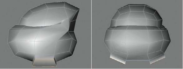
— Figure 4.17: Extruding the upper leg.
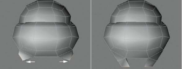
— Figure 4.18: Preparations for the second extrusion.

— Figure 4.19: Extruding legs and feet.
Extrude and move these faces as shown on the left of Figure 4.21. This will look a bit chaotic WITHOUT HYPERNURBS smoothing, but after the activation of HYPERNURBS it will all come together, as shown on the right side of the figure. The outer toes should huddle against the big toes and give the front of the feet a nice appearance.
The HYPERNURBS smoothes and gives the roughly modeled shape a nice organic form. However, this can be a bit distracting on the bottom of the feet, where the sole should be plain and less curved. This can be achieved by adding a polygon ring. Select all polygons on the bottom of the feet, but skip the two v
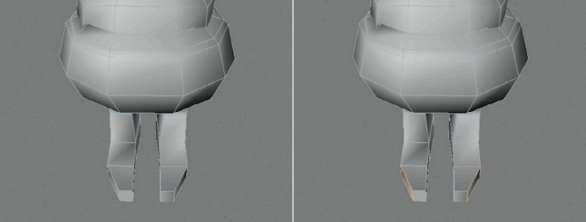
— Figure 4.20: Shaping the big toe.
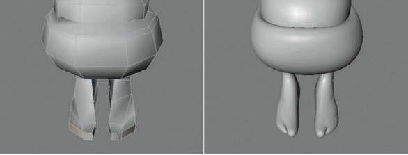
— Figure 4.21: Shaping the toes.
Use the iNNer eXtrude command in the StruCture menu to shrink these faces. Figure 4.22 shows the desired result on the very left. The images in the middle and on the right show that the soles have become nice and flat.
FINISHING THE FEET
To be able to show DETAILS like the WIDTH of the toes or the indication of an ankle, we will make some additional kNiFe cuts in looP mode. Figure 4.23 shows some suggestions for these cuts, indicated by arrows. All toes are cut once in the middle, and we will add another subdivision at the last segment of the leg. Use the new points to refine the shape in these areas. At the same time, these subdivisions will improve the maneuverability of the feet during the animation.
Modeling the Arms
We will now take care of the arms, which start at the sides of the back of the head and end with hands that will lie on the floor. We start again with a simple extrusion of two faces, as shown on the left in Figure 4.24. In order to set the profile of the arms more exactly, the points of the newly extruded faces should be straightened, as seen in the middle of the figure. Switch to USE POINT TOOL mode and select the two lower points of each of the extruded faces. Force them onto one plane by entering 0 at the Y and Z SiZe settings of the COORDINATE MANAGER. Then the faces under the arm stumps that are almost parallel to the floor can be extruded further downward, as shown on the far right in Figure 4.24.
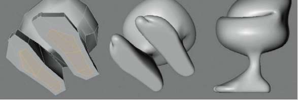
— Figure 4.22: Extruding the bottom of the feet inward.
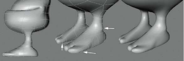
— Figure 4.23: Shaping the feet.
Another extrusion extends the arms up to the location of the wrists and leads them in a soft curve downward and back, as shown in Figure 4.25. The finishing touch is made with the eXtrude iNNer command, which slightly tapers the arms. Pull these new faces slightly backwards along the WORLD Z axis so a little rounding at the end of the arm stumps is created. You can see this in the middle and on the right of Figure 4.25. It is helpful here as well to turn on the HYPERNURBS smoothing to better evaluate the curvature of the arms.
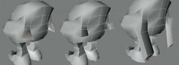
— Figure 4.24: Modeling shoulders and arms.
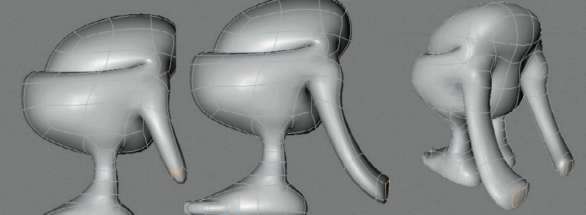
— Figure 4.25: Extending the arms and shaping the transition to the hand.
MODELING THE HANDS
As can be seen on the far left in Figure 4.26, we will widen the ends of the arms a bit. The arrows in the figure indicate the movement of the two edges. There you also can see the two highlighted faces at the ends of the arm stumps, which will be extruded in three steps and rotated slightly to depict the palms and the stylized fingers at the end. Figure 4.27 shows on the very left how the smoothed HYPERNURBS shape might look.
Now the only parts missing are the thumbs, which we can shape out of the original third face of the arm stumps. Extrude this face a short distance in the direction of the fingers, as shown on the right of Figure 4.27. Then select the two faces that are marked with colored points in the figure and extrude them one step diagonally upward, to shape the actual thumb. Figure 4.28 shows (highlighted) the extruded faces and the desired form of the thumbs. Here you can refer to the original shape in your Doodle sketch.
This completes the modeling of the character for the moment. As I promised, we were able to use just a few tools and we kept the number of polygons very low. This is especially important with characters built for animations, since it keeps the efforts for texturing and the so-called rigging at a manageable level. Figure 4.29 shows you again the whole character in the side view. If you are looking for more information and workshops about modeling and texturing complex characters, then I recommend my book virtuAl viXeNS, published by Focal Press. The workshops there can be completed in CINEMA 4D as well. A short excerpt, in the form of a workshop, can be found as a bonus on the disc accompanying this book.
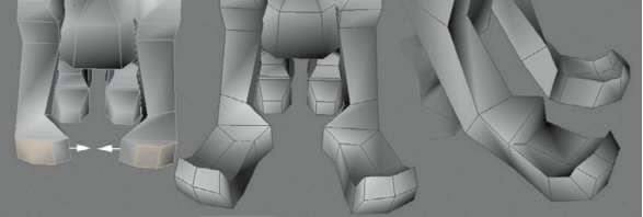
— Figure 4.26: Shaping the palm and the stylized fingers.
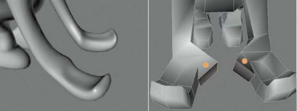
— Figure 4.27: Modeling the base of the thumbs.
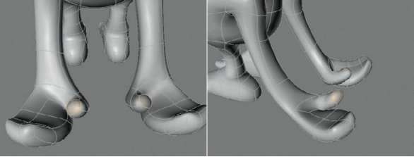
— Figure 4.28: Finishing the thumb.
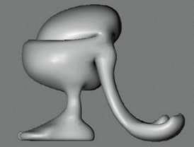
— Figure 4.29: The finished character.
Applying Joints and Weightings to the Character
Generally, it is recommended that you always add joints to all characters. They offer the most comfortable tools for weighting, which is the connection of the geometry to the animation of the joints. But there are situations where the character has to be optimized for exporting to other programs. Then the use of bone objects might be better. We will talk about both systems, starting with the joints.
The Joint Tool
One of the main differences between joints and bones is that joints determine only one position in 3D space and therefore aren’t able to deform themselves. Only by using a hierarchical structure of several joints are chains created that can be indirectly used for deformation. The advantage of this is that joints can be oriented individually WITHOUT disturbing the course of the chain. This is different with bones. They have a defined length and are comparable to a rigid object. When a bone is rotated, then the subordinated objects are automatically rotated and moved as well. Joints also offer an automated weight mode that is not available with bones.
If you have to work with bones, existing joint setups can be converted to a bone hierarchy. This procedure will be discussed later in this example.
For the creation of joints, activate the joiNt tool in the ChArACter menu. It allows the creation and positioning of joints in the editor viewports. In the ModiFierS group within the oPtioNS of the tool in the ATTRIBUTE MANAGER, you will find the presets of the keyboard shortcuts for using this tool. You can change them to your liking. The (Ctrl) keys are the presets for generating new joints by clicking in the editor viewport; just by holding the mouse button, previously set joints can be moved. A (Shift) click onto a connection between two joints creates a new joint halfway. Figure 4.30 shows these basic settings in the lower part of the dialog.
SYMMETRY SETTINGS
Generally, characters are modeled symmetrically. The arms and legs are positioned at identical locations on both sides of the body and have the same structure. With the SymMetrY settings of the joiNt tool, we can save ourselves some work with such body parts. Only the joints of one arm or leg have to be drawn in. The other half of the body is then automatically amended. The necessary settings can be found in the SYMMETRY part of the joiNt tool. These settings are shown in the middle of Figure 4.30.
The SYMMETRY function is activated in the corresponding menu. The setting NoNe deactivates the symmetry so joints are only created where a (Ctrl) click is made. At the drAw setting, joints are set symmetrically according to the PLANE and origiN settings. The liNk setting functions in a similar manner but generates a permanent connection between the joints on both sides, so symmetrical changes at the joint positions can be applied, even when the tool has been deactivated. Depending on the kind of character, this can be helpful or distracting for its future animation.
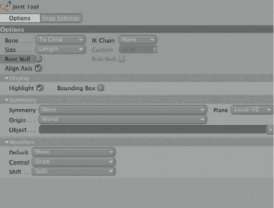
— Figure 4.30: The dialog of the Joint tool.
PLANE determines the mirror plane. For a character visible in the front XY viewport, this would be the WORLD YZ PLANE. If the character was modeled in an angled way, then the planes can be defined in the local coordinate system. origiN defines the position of the mirror plane in 3D space. This could be the WORLD system, the root (the uppermost joint of the hierarchy), the PAreNt of the currently active joint, or any OBJECT of the scene. This object can then be pulled into the OBJECT field in the dialog. The huB setting accesses the same option in the dialog of the joints. When this option of a joint is activated in its symmetry settings, the joint automatically acts as the origin during painting of symmetrical joint chains.
GENERAL INFORMATION ABOUT INVERSE KINEMATICS
The options of the joiNt object determine how the joints are evaluated with automatic weighting and whether an inverse kinematics solution should be generated after the joints are drawn. As the name indicates, inverse kinematics is the flow of movement through the joint hierarchy. Without any other preparations, all objects can be animated with just forward kinematics. This is often abbreviated with FK. Here, all bones have to be rotated manually to create the desired pose. The advantage is that we have full control over the position and rotation of every object. To clarify the disadvantage of this animation technique, imagine a character that is supposed to do a deep knee bend. By animating with FK, the character would have to be moved completely downward. Then all bones or joints would have to be rotated so the feet are again planted on the ground—a very complicated procedure. When the character is animated with inverse kinematics, or IK, then it would only have to be moved downward. The feet automatically remain fixed to the floor and the legs automatically bend.
Because of the fixed position of the feet, an energy flow is generated through the legs up to the beginning of the corresponding hierarchy. Some settings in CINEMA 4D call it the anchor, which defines the uppermost link of such an IK chain. Despite the practical use of IK, this technique isn’t used everywhere on the character. Arms, fingers, and the complete spine/neck/head hierarchy are generally animated with FK. An exception would be a character that is supposed to do a headstand. Then it would be better to use IK to fix the hands and the head on the floor, while the body would be moved manually with FK.
THE IK CHAIN SETTINGS
Let us get back to the settings of the joiNt tool. In this tool, such IK relationships can be created automatically when the joint chain is created. Figure 4.31 shows a simple example. Use the settings of the ik ChAiN menu in the oPtioNS of the joiNt tool. At the 2d setting, the future mobility of the joints is restricted by an imaginary plane that is placed at the starting position of the joints. This can be helpful to prevent the lateral movement of the knee when doing a knee bend or to avoid the backward bending of the knee when the body is moved up and down. When complete mobility is needed, then the 3d setting should be used. Then, only the position of the target object is important for the IK chain. All involved joints then try to move toward the target point as much as possible. The SPliNe setting assigns in a newly created spline object, after the deactivation of the joiNt tool, a point to every active joint of the chain. With the movement of these spline points, the position of these joints can then be changed. This can be useful for the depiction of ropes, longer animal tails, or the spine of a character.
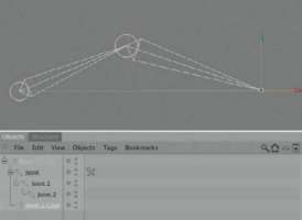
— Figure 4.31: Automated creation of an IK chain.
In the 2d and 3d settings the Pole Null option can also be selected. It will add another Null object after the joiNt tool is deactivated. The Null object is used for the orientation of the Y axis of the joints. Figure 4.32 shows a simple example. It can be used for additional control over the rotation of joint connections and avoids possible unwanted rotations around the longitudinal axis. The setting NoNe prevents the automatic generation of IK relationships. They can still be manually created later.
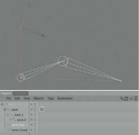
— Figure 4.32: An IK chain including Pole Null vector.
BONE SETTINGS
The BoNe menu determines how the bone connections between the joints are interpreted. At the AXiS setting, these connections run, like normal bone objects, along the Z axis of the joints. With an active AligN AXiS option, the joints are automatically oriented so their Z axis points to the following joint. With to Child, the bone connection ends at the subordinated joint object. With to PAreNt, this direction is reversed. The direction of the bone connections is important for the assignment of weightings. Depending on the choice in the BoNe menu, the weightings are applied either to the section of the following joint or to the section in between the current joint and the one above. The results are quite different and cannot be switched later. The setting to Child should be the more logical choice in most cases.
THE SIZE OF THE BONES
The connections between the joints are also called bones but aren’t real objects, as is the case with the bone objects. Therefore, the size of these joint bones can be determined independently from the joint positions. In the SiZe setting leNgth, the measurements of the drawn bones adjust to the length of the SEGMENTS between the joint objects. At CuStoM the circumference of the bones can be set with the CuStoM value, as shown in Figure 4.33. These settings are a mere visual change and don’t have anything to do with the future function of the bones and joints. Also, the highlighting of the joints and bones in the diSPlAY part of the joiNt tool can be influenced with the highlight and BouNdiNg BoX option. highlight changes the brightness of the bone when the mouse pointer is above it. BouNdiNg BoX draws an orange box, familiar to us from the selection of normal objects, around the bone.
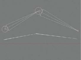
— Figure 4.33: Different size settings for the bones.
The Joint Setup of the Character
Let’s get back to our character. We will use the joint tool to create some joint chains. It is helpful to orient ourselves on an imaginary skeleton of the character, as if we were working with a living creature. On every spot where the character needs a joint or where you want to gain control over the mobility, you have to place a joint. Many joint objects in a section can increase the mobility of the character, but also make it more difficult to animate. We have to find a compromise between the two goals.
After activating the joiNt tool we will start with (Ctrl) clicks in the side viewport, starting at the hip, to place the joints marked
1, 2, and 3 in Figure 4.34. I used the standard settings of the joiNt tool, no SYMMETRY, and no ik ChAiN. The bones are aligned to Child and the axis aligned with AligN AXiS. The root Null option can remain deactivated; otherwise, it would create another Null object under which all other created joint objects would be subordinated.
The joint marked number 4 in Figure 4.34 is supposed to be connected to joint number 2. Therefore, the creation of the joints is finished after the creation of joint 3. Then select the joint second from the top in the OBJECT MANAGER and set, with another (Ctrl) click, joint 4 at the crown of the character. Joint 4 is automatically subordinated under the last selected object in the OBJECT MANAGER. That way, you can generate branched joint hierarchies WITHOUT having to leave the joiNt tool. The main body now contains enough joints.
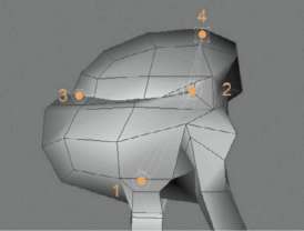
— Figure 4.34: The joints for the body and the head of the character.
THE RIG OF THE LEGS
We now move on to the legs. These naturally belong under the joint object of the hip, which is generally called the root joint and acts as the uppermost object of a character rig. Because the legs of our character are symmetrical, we can save ourselves half the work by using the SYMMETRY function of the joiNt tool. Activate drAw as the SYMMETRY option for the drawing of the joints and use WORLD as the origiN and YZ as PLANE. Local or WORLD system doesn’t make a difference here, as long as the sphere wasn’t rotated around the Y or Z axis in the beginning of the modeling. Figure 4.35 summarizes these settings.
Select the hip joint in the OBJECT ManAger and create, with (Ctrl) clicks in the side viewport, the joints marked with the numbers 1 to 5 in Figure 4.36. After creating the first joint, move it in the front viewport along the X axis so it is placed in the correct position at the base of the leg. Because of the activated symmetry, the mirrored joint in the other leg is automatically moved as well; we don’t have to hold any other key for moving the joint. Just click on the yellow circle of the joint object and pull it to the desired position. As you continue to create the remaining leg joints in the side viewport, they should automatically be generated in the same ZY plane and placed in the center of the legs. Check and correct this, if necessary, in the front viewport.
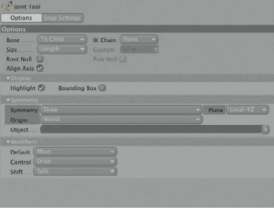
— Figure 4.35: The leg joints can be created symmetrically.
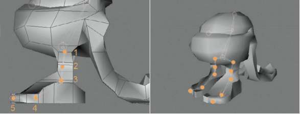
— Figure 4.36: The joint objects within the legs of the character.
Regarding the number and location of the joints, the order of the joints shown in Figure 4.36 has proven to be the best setup. In addition to the joint object of the hip, a joint is placed at the knee, one at the ankle, and another one at the base of the toes. The connecting joint is placed at the tip of the toes. Depending on the complexity of the character, it might be useful to create individual joints for all toes. This will not be necessary for our simple comic figure.
THE RIG FOR THE ARMS AND LEGS
Normally, it would be enough to use three joint objects for the arms: one for the shoulder, one for the elbow, and one for the wrist. The joint objects for the hands and the fingers would be connected to these. In our case, I would like the arms to be more elastic, though, WITHOUT a set joint in the center. As you can see in Figure 4.37, I created an almost evenly subdivided joint chain from the shoulder down to the wrist. The wrist is indicated in green in the figure.

— Figure 4.37: The joint objects in the arms and hands.
The joints of the arms can be created symmetrically as well. Therefore, keep the settings in the joint tool which we used for the legs. Select the hip joint again as the uppermost object for the chains about to be created, and start in the side viewport with the placement of the first shoulder joint. Correct its position by moving it in the front viewport, then continue to set the joints down to the wrist in the side viewport. From there, add two more joint objects that span the length of the palm and the fingers, with the last joint placed at the finger tips. In the object Manager select the joint that is placed at the wrist, marked in green in Figure 4.37. Based on its position add three additional joint objects to enable the mobility of the thumbs. These joint objects can be placed properly into the character using the top viewport. Correct their location if necessary in the other viewports. That completes the job of the joint tool and all necessary joint objects have now been created.
The Weight Tag and the Creation of Weightings
Contrary to the function of the bone objects, the joint objects aren’t deformers. Therefore, they don’t have to be placed in one group with the object to be deformed. It is recommended, though, just as with the bone objects, that you give all joint objects new names before the next step. Figure 4.38 shows an example and the current hierarchy of the joints in the object Manager. You can see there that a new tag was created behind our model Trolly. This weight tag will be needed later for the assignment to and management of the weightings of the joints. It is created by right clicking on the character model in the object Manager and by selecting Character tags>weight. This automatically opens the weight tool, and its settings are then shown in the ATTRIBUTE MANAGER. This tool can be used for the individual painting and correcting of the weightings. The big advantage of joints is that they can add automatically generated weight distributions, meaning that a majority of the manual weight painting can be skipped. Therefore, click again once on the weight tag in the OBJECT MANAGER to see its settings in the ATTRIBUTE MANAGER. Figure 4.38 shows the tag dialog.
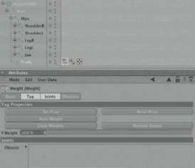
— Figure 4.38: The weighting tag.
In the joiNtS area of the weight tag, there is still an empty list that has to be filled with all the joints that will influence the object. In our case these are all the joints previously created. Select the root joint of the hip, right click on it, and choose SeleCt ChildreN in the context menu. The dialog of the weight tag then disappears from the ATTRIBUTE MANAGER, but you can activate it again with multiple clicks on the arrow pointing to the left in the title bar of the ATTRIBUTE MANAGER. With drag and drop, pull the selected joint hierarchy into the OBJECTS list of the weight tag, as shown on the left of Figure 4.39. If you pulled an object into the list by accident, you can DELETE it by right clicking and selecting reMOVE in the context menu.
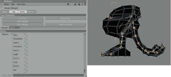
— Figure 4.39: The weight tag with applied, but not weighted, joint objects.
MANAGING AND AUTOMATICALLY CREATING WEIGHTINGS
Now it gets more interesting in the TAG part of the weight tag. There you can find the Set PoSe button for setting the start pose of the rig. This saves the current position of the joint objects so you can always go back to the original pose of the rig with the reSet PoSe button. This can be helpful if the assigning of inverse kinematics results in unwanted torsions of the character. The saved start pose is also important for the future calculation of the model deformation. CleAr weightS DELETEs all existing weightings of the joints in the list, and reMOVE eMPtY DELETEs the joints that don’t carry any weighting for the object.
Auto weight will now get interesting for us since it automatically calculates weightings for the joints in the list. In the best possible case, we could then start immediately with the animation. In practice, though, evaluation and partial correction of the automatic weightings are necessary, but the time saved is still tremendous. Use the Auto weight button and watch the display of the character model in the editor. As shown in Figure 4.40, the character should now be shaded with light colors. The previously black display was an indication that weightings didn’t exist yet.
As with the vertex maps, this weighting system is combined with color and brightness values that show the strength of the weightings in the editor. The automatic weighting ensures that every point of the object is assigned to a nearby joint and weighted for that joint. The object now appears to be completely weighted.
EDITING AND DISPLAYING INDIVIDUAL WEIGHTINGS
To get an overview of the individual weightings of each joint, double click onto the weight tag in the OBJECT MANAGER or select the weight tag directly in the ChArACter menu. In the joiNtS area of the tool dialog you can find a listing of all the joints in the scene. When you click on a joint in this list— this is why it is so important to give the joints meaningful names—you get a colored display of the weight distribution for this joint. In Figure 4.41 you can see as an example the automatically created joint weighting at the jaw joint of the character. The unwanted weighting of the bottom jaw and stomach of the character is clearly visible.
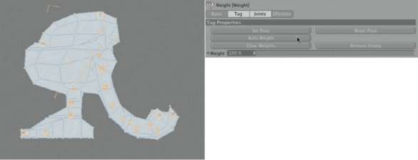
— Figure 4.40: The character after assigning automatically calculated weightings.
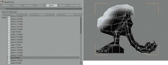
— Figure 4.41: Individual weight display.
Options of the Weight Tool
The weight tag offers in its options and Paint settings several options for editing such unwanted weightings. Figure 4.42 shows the corresponding part of the dialog that we will now go through. The majority of these functions are self-explanatory. The Strength sets the INTENSITY of the applied weightings between the extremes 0% and 100%. When Auto NorMAliZe is active, all subtracted or newly painted weightings of a joint are automatically synchronized with the remaining joint weightings. That way, every point automatically keeps a weight strength of 100%.
The MODE determines whether weightings are applied with every pass of the tool or subtracted from the joint with the erase function. Weightings can be applied absolute or painted with soft edges as well. Bleed increases the already weighted areas of the object and reMAP allows the editing of existing weight Applying Joints and Weightings to the Character values with a curve. This effect is comparable to working with the gradient curve in image editing. PruNe is equal to a clipping function. Points with weighting less than the strength of the weight tool in the dialog are reduced to 0% INTENSITY. The two ClAMP options, including their sliders, can be used for the definition of upper and lower limits of the applied and manipulated weightings. The NorMAliZe button is helpful if you haven’t used the Auto NorMAliZe option. With the use of this button, the weightings of all objects affected by the currently selected joint object are normalized. With APPLY All, all points of the object receive the value specified by the STRENGTH of the currently selected joint. This of course also changes the weightings of all the other joint objects. When points, edges, or polygons of the object are selected, you can apply to them, with APPLY SeleCted, a weighting based on the STRENGTH setting. With reASSigN to SeleCted, all elements not selected receive a weighting of 0%. In the ChArACter menu you can find the weight eFFeCtor. It works like a small force field with adjustable falloff radii and is able to include points of the object for the joint to pull. To be affected, this object has to be subordinated under a joint and listed in the OBJECTS list of the weight tag as well. With the help of this object, the deformation between two joints can be individually changed to achieve smoother transitions. The object itself is not a deformer in this case, but instead only supplements the influence of the joints on the geometry. This influence can be recalculated into weightings with the Bake eFFectors button. The weight eFFector can then be removed from the joint. The From vertex Map and to vertex Map functions convert the weighting into a vertex map or transform the vertex map intensities into a joint weighting.
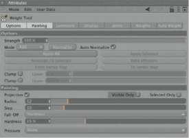
— Figure 4.42: Settings for the painting and editing of the weightings.
Paint Settings of the Weight Tool
The Paint radius is set in the paint settings of the weight tool, as well as whether visible only or Selected only should be painted. When Projection is active, all points that are located under the tip of the tool in the current viewing angle in the editor viewport are weighted. Otherwise, the tool follows the contours of the surface and makes areas, which are otherwise hidden, accessible for weightings. Also with this activated tool, the risk of accidentally weighting hidden points is reduced.
The Step function determines how many steps are used to apply or edit weightings. The higher the value, the more detailed the work can be. The Fall-off function controls, within the boundaries of the radius value, the fa ll off of the weighting strength at the edge of the tool. There are several functions available that only make sense if you work with detailed geometries and capture a number of points with one brush stroke. For example, hardness works like a contrast function. Small hardness values cause a softer transition to the outer radius of the tool; high values, on the other hand, cause an almost constant application of weightings up to the edge. In the Curve settings you can manipulate this fa ll off curve yourself in a graph and create more unique weight applications, like a weighting just at the edge of the tool tip.
The Pressure setting is relevant if you want to use the tool in combination with a graphics tablet. The pressure of the pen changes the radius of the weight tool in the RADIUS setting, the INTENSITY of the weight application in STRENGTH, and the falloff curve of the tool in hArdNeSS. The NoNe setting deactivates this special behavior resulting from the use of a pressure-sensitive graphics tablet.
Now you know everything about the options for the manual application of weightings. In the weight tool, select the joints, one after the other in the corresponding part of the tool dialog, to evaluate their weightings. When you encounter a section with wrong or unfavorable weightings, like with the jaw joint, activate a 100% STRENGTH in Abs MODE and leave Auto NorMAliZe active in the oPtioNS section of the dialog. Then repaint the points, which should be moved when the jaw is rotated. It might help to switch to a line display in the editor to reach the points positioned within the model. Repaint the wrongly weighted points with a STRENGTH of 0% or use the erASe mode of the tool. Figure 4.43 shows the corrected weighting of the jaw joint.
Faulty weightings are also possible at the upper joints of the arms, since the geometry of the body comes very close to the arms in this spot. Delete any weighting for the lower arm joints at the body of the character, as shown in the before and after images in Figure 4.44.
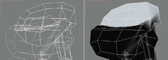
— Figure 4.43: Correction of the jaw weighting.

— Figure 4.44: The new weighting of the upper arm joint.

— Figure 4.45: Evaluating the weightings by rotating the joint objects.
Checking the Weightings and Deformations
As previously explained, contrary to the bone objects, joints are not deformers. Therefore, despite the previously applied weighting, there won’t be a deformation when the joints are rotated. We will need to use the so-called Skin object that is found in the Character menu. Simply subordinate it under the object to be deformed or under its superordinated object.
Figure 4.45 shows the resulting hierarchy. You can see that the joints don’t have to be in hierarchical relation to the objects that are to be animated. When the Skin object is subordinated, the rotation of single joints should move the geometry of the character. For the first tests it would be best to check critical areas such as the jaw joint, the thigh, and the shoulder. If strange deformations occur, go back to the weight tool and correct the weightings again until the deformations are correct.
Activating Inverse Kinematics and Dynamics
The character could now be animated by using forward kinematics. The joints would have to be individually rotated and, in the case of the hip joint, moved as well. In places where the character is more often in contact with other objects, the use of inverse kinematics makes more sense. This is generally the case with the feet and legs. In the OBJECT MANAGER, hold (Ctrl) and select, one after the other, the four joints of the leg. They are marked by colored points in Figure 4.46. The joint of the knee can be skipped over.
In the ChArACter menu, while still holding the (Ctrl) key, select ik ChAiN. It applies IK tags to the currently selected objects and automatically creates three external help objects for the foot. Figure 4.46 shows these additional objects on the right side. These are generic Null objects that apply a magnetic force through the IK tags to the joints. That way, the joint position can be controlled from outside the joint hierarchy.
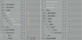
— Figure 4.46: Creating handlers for the legs.
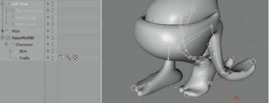
— Figure 4.47: Using external handlers.
To make it easier to use these external handlers during an animation, create a Null object and place it under the sole of the foot for which you just created the IK. Null objects can be found in the OBJECTS menu of CINEMA 4D. Then subordinate the three external handlers under the new Null object, as shown in Figure 4.47. When you now move this group of handlers backward along the Z axis, the foot should move backward as well and automatically lift the heel while the front part and the toes remain on the ground. As you can see, quite complex movements can be achieved by a simple movement of the handler objects. Do the same with the joints of the other leg.
ORIENTING JOINT OBJECTS
The uniform orientation of the joint objects in a continuous chain is not as critical as with bone objects, but helps nonetheless. While the orientation to the following joint was activated during the creation of the joints, their rotation around the Z axis can vary, as a quick look at Figure 4.48 proves. As you can see by the arrows, the Y axes of the arm joints are uniformly oriented up to a point. However, in the area of the hands there is a –180° rotation. This could cause unwanted rotations in a future animation, so align these joints with the joiNt AligN tool in the ChArACter menu.
This tool can orient selected joints toward objects. We will utilize this for aligning the Y axis of the joints. Create a new Null object that we can use as the target object for the Y axes. Place it above the hand of the currently selected joint chain. An appropriate positioning can be seen on the right of Figure 4.48. The Z axis is automatically aligned in the direction of the bones.
The figure also shows the necessary settings in the dialog of the tool. The Z AXiS of the joints should still point in the direCtioN of the next BoNe. In uP AXiS we define the Y axis of the joints and orient them, with the uP direCtioN selection of AiM, toward the new Null object. With a click on the AligN button, all joint axes are updated WITHOUT changing the position of the joints.
USING MOCCA IK
Besides the IK tag, for the inverse kinematics of the legs there is also the MoCCA ik tag. It offers additional possibilities for overlaying inverse kinematics with dynamic effects such as drag or gravity. We will now use this tag at the arms of the character. Select all joints of an arm from the shoulder down to the wrist and apply the tag by right clicking and selecting ChArACter>MoCCA ik.
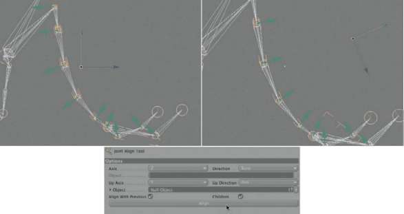
— Figure 4.48: Automatically orienting joint objects.
Contrary to the previously used ik tags, the MOCCA IK tags have to be restricted with an ANChor. It defines the uppermost object of an inverse kinematics chain. Select the MoCCA ik tag at the shoulder joint and activate the ANChor option in the TAG settings of the ATTRIBUTE MANAGER, as seen on the right in Figure 4.49. This automatically turns on the options for the dynamic behavior of the joints or bone objects that follow in the hierarchy. My settings can also be seen in the figure.
SPeed is a multiplier for the calculation of dynamic effects. Higher values cause faster movements and lower values cause the opposite. drAg is a kind of resistance against impulses. A drag set too high can, in extreme cases, stop the dynamic effects altogether. grAvitY, on the other hand, pulls all objects downward along the Y axis when used with a negative value. A value of –9.81 represents the average value of earth’s gravity. Since we can’t assign mass to the bones, you should use the drAg and grAvitY values to create the desired behavior of movement. drAg controls the passing of rotations from one bone to another. High values slow down the passing of changes through the bone chain, causing the individual bones to try to stay in their current position longer. In this way, high drag values can be used to simulate big, heavy masses.
Select the MoCCA ik tag of the wrist joint and take a look at its CoNStrAiNt dialog. External reference objects can be assigned or created within this dialog. The choices are the tArget object that magnetically affects the position of the joint and an uP veCtor object that is used to point one of the axes of the joint or bone toward it. The use of the APPLY button behind the tArget field generates a new Null object that can be used to move the entire joint chain between the ANChor shoulder and the wrist. As Figure 4.50 shows, I renamed these external Null objects handl and handr, respectively. The joint chain of the other arm is treated in the same way.
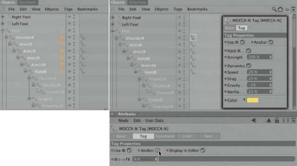
— Figure 4.49: Assigning MOCCA IK tags.
Aligning the Up Vector
We have already uniformly aligned the joints of the arms. In order to keep it that way during an animation and to avoid unwanted rotations, we will use an external object to roughly orient one axis of the joint to it. This results in restricted mobility for the X and Y axis of a joint. This alignment is called up vector.
For the assignment of an up vector, do the same as with the target object. First, select the MoCCA ik tag behind the first joint, under the anchor of the corresponding arm, and use the Add button behind the up vector field to generate a new Null object. This Null object is then placed above the hand. If you still have the Null object that we created for the alignment of the joints, then use that one instead. Simply pull this object into the uP veCtor field, which makes the use of the Add button unnecessary.
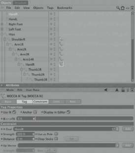
— Figure 4.50: Creating and assigning an external target object.
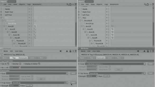
— Figure 4.51: Aligning the Up Vector.
Then select all following MoCCA ik tags in the OBJECT MANAGER with a frame selection and, in their dialogs, pull the new Null object into the uP veCtor field as well. Figure 4.51 shows the last few steps.
Since the joints might have been rotated, you should deactivate the SkiN object for a moment by simply clicking on the green checkmark behind it in the OBJECT MANAGER. The geometry of the character then automatically jumps back to the state in which it was modeled. In case their position changed, use the two external handlers at the wrists to place the joint chains in the center of the arms. Then click on Set PoSe in the weight tag of the character to save the new angles and positions of the joints. Activate the SkiN object again by clicking on the now red cross in the OBJECT MANAGER. The character should remain unchanged. Figure 4.52 shows these last steps. On the left side you can see the supporting display of lines for the Up Vectors and the yellow connecting line that automatically spans between the anchor and the last link of a MoCCA ik chain.
CONVERTING JOINTS TO BONES
We are now at a point where we could start with the animation. But since I would like to demonstrate a possible exchange of the animation with an external program that doesn’t know joints, we will first convert the current joint rig to a bone setup. All weightings and IK tags remain the same.
Select the root joint and then choose ChArACter>CoNverSioN>CoNvert to BoNeS. A new bone hierarchy is generated, displayed on the left in Figure 4.53, which consists of already fixed bones, as indicated by the checkmark. In order to exchange the joint hierarchy with the bones, you first have to DELETE the SkiN object. It is not needed anymore, since bone objects themselves are deformers. Then DELETE the entire group of joint objects, but keep the external help objects that were automatically assigned to the new bone objects during the conversion. Because deformers always have to be subordinated, these bones now belong in the group with the model of the character. To prevent unwanted distortions do the following. First, select the uppermost bone object and then select SoFt ik/BoNeS>reSet BoNeS in the ChArACter menu. The question about the subordinated object has to be confirmed with OK. The bones lose their deforming properties for now and can be pulled into the Null object group of the character. Figure 4.53 shows these steps on the left side. On the right you can see how else the joint objects differ from the bone objects, because the structure changed at the locations where the rig branches out. This change of location doesn’t influence the deformation of the character, but you can take the time to align the bones again the way you think they need to be. For example, you could pull the bones of the upper part of the head and the bones of the arms out of the hierarchy, align the stomach bone to the imaginary spline, and then subordinate the head and arm bones again.
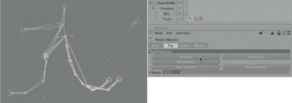
— Figure 4.52: Visual depiction of the constraints.
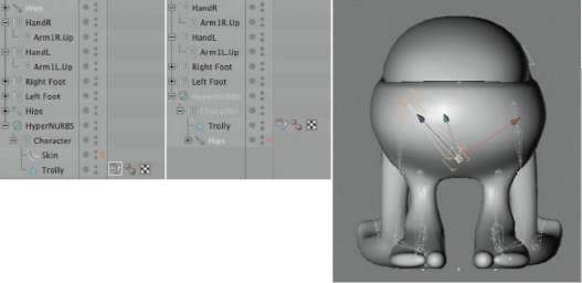
— Figure 4.53: Converted joint rig.
After the bones are realigned, fix the bones to their current location. Again, select the uppermost bone and this time select ChArACter>SoFt ik/BoNeS>FiX BoNeS. Also here, confirm with an OK that the subordinated bones should be fixed as well. This completes the conversion from a joint rig to a bone rig and we can start with the animation. Our character could use some color and textures, though. Therefore, we will use this opportunity to take a look at the BodyPaint 3D module of CINEMA 4D.
TEXTURING OBJECTS WITH BODYPAINT 3D
Many surfaces can be textured with shaders or, for example, with a plane or spherical projection of images. In some cases these methods don’t go far enough, like when a surface is supposed to be changed in a certain way by painting on it, or when an image structure should follow a curve on the object WITHOUT being distorted. In such cases the creation and unwrapping of so-called UV coordinates is necessary beforehand. These coordinates cover objects like a second skin and determine the projection of the material onto the surface. Imagine that these coordinates are like the unfolding of the entire surface onto one plane. Of course, it is much easier to project the texture that way than onto the curved surface.
Even though BodyPaint is completely integrated into CINEMA 4D, it is not immediately apparent. When you switch into one of the BodyPaint 3D layouts with wiNdow>lAYout, all managers and tools of BodyPaint 3D become visible. In this menu there is the BP uv edit layout, which is optimized for working on the UV coordinates, and the BP 3d Paint layout, which is meant to be used for the painting and editing of textures.
Creating a New Texture
In the first step you should create a new material in the MATERIAL MANAGER for our comic character. In the COLOR channel of this new material in the texture area, click on the small triangle and select Create New te xture from the drop-down menu. Then a dialog opens, as shown in Figure 4.54, in which you can define the name, size, and background color of the desired texture. After closing the dialog with ok, assign the material to the character and then change to the BP 3d Paint layout.
In the MATERIAL MANAGER you will now find our material in a slightly different format. Every material can contain a variety of textures in all possible channels. Before we edit the textures, we have to tell BodyPaint 3D which of them will be manipulated in order to optimize the memory. Behind every material there is a red cross that can be activated by clicking on it, which turns the symbol into a pen. Now the textures within this material can be edited in BodyPaint 3D. In the small displays of the textures in the materials, you will notice the abbreviation of the channels containing the textures—in our case it’s a C since the texture is used in the color channel. Just like in Photoshop, there is also a toggle switch for changing between foreground and background color. You can see these elements on the left of Figure 4.55.
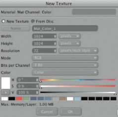
— Figure 4.54: Creating a new texture.
As in the common graphics programs, in BodyPaint 3D you can build textures with different layers and allow these layers to interact with each other. All of this is done in the layers section, seen in the middle of Figure 4.55. There you can create new layers or combine them with the FUNCTIONS menu, shown on the right in the same figure. These layers can also be multiplied with each other or used for other color changes.
The majority of the more important paint tools can be found as icons on the left side of the layout, as shown in Figure 4.56. There are many familiar tools, such as a brush, stamp, eraser, and tools for text. The settings for the selected tool can be found in the ATTRIBUTE MANAGER. Figure 4.56 shows as an example the settings for the brush and its corresponding color settings. By using diverse parameters, the size, opacity, and shape can be adjusted. The use of bit-maps is also possible. A large number of brush presets are included and can be seen after clicking and holding the mouse button on top of the preview image of the brush, in the top left of the ATTRIBUTE MANAGER.
Unfolding the UV Coordinates of the Character
Before we start the painting of a complex surface, we have to prepare the UV coordinates. With basic shapes like the cylinder, sphere, cube, and the spline-generated NURBS objects, this isn’t necessary since these objects are already generated with UV coordinates. However, as soon as changes are applied to these objects, such as extrusions or manually generated faces, the existing UV coordinates won’t fit anymore because they are not automatically updated by all tools.
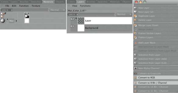
— Figure 4.55: Edit textures in layers.
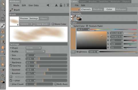
— Figure 4.56: COLOR and brush settings.
To edit the UV coordinates, first switch to BP uv edit. In the icon palette at the upper edge you will find some familiar icons, such as the ones used to switch to point, polygon, or USE edge tool mode. But there are new, similar-looking icons as well, consisting of a texture symbol as well as one for points and one for a polygon. With these icons you can switch to the editing mode of the UV coordinates, which can be edited as UV polygons as well as UV points.
We should do this step by step, in order for the UV polygons of the character to unfold as flat as possible. It is helpful that the selection of polygons can, at the same time, be used as a UV polygon selection. Start by selecting the polygons of the lower part of the body, as well as the visible outer SEGMENTS of the lower jaw, as shown in Figure 4.57. The familiar selection methods are available as icons in the upper icon palette.
Switch to USE uv POLYGON edit tool mode and open the dialog of uv CoMMANdS in the uv MAPPiNg group. This section of the BodyPaint 3D layout is shown on the bottom of Figure 4.57. There you can find a number of standard commands for mirroring, combining, and maximizing the selected UV polygons. It is important to know that the value range of the UV coordinates spans only between 0 and 1. Deviant values are possible as well, as long as tiling is active in the material. Then the UV polygons will receive a part of the neighboring tile.
Interactive Mapping
This value range of the original tile of every texture, the coordinate range between 0 and 1 in the X and Y direction, is depicted as a highlighted square. You can find this texture view in the BP 3d edit layout directly to the right of the editor viewports. Later, when placing and scaling the UV polygons, you should make sure that all faces are located within this highlighted square. However, we are not that far yet and first have to unfold the UV polygons. We will use the STARt iNterACtive MAPPiNg button in the uv CoMMANdS. This mode allows us to restrict one of the standard projections, such as spherical, cubic or flat mapping, to the currently selected polygons and to calculate the unwrapping of the UV polygons. This sounds more complicated than it actually is.
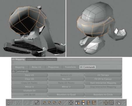
— Figure 4.57: Interactively texturing selected polygons.
In the ATTRIBUTE MANAGER you can now see the familiar dialog of a TEXTURE TAG, in which you should select an appropriate projection mode for the selected polygons. Base this decision on the geometrical shape of the selection. Despite the changes to our character’s head, which is also the area of our polygon selection, it still resembles a sphere. Select the PROJECTION type in the ATTRIBUTE MANAGER. Adjust the projection preview in the editor viewport using the scale, move, and rotate tools, so the unwrapping of the faces is as flat as possible. Figure 4.58 shows a possible placement and rotation of the projection preview in the side viewport.
While working with these settings, the texture view helps since you can see the resulting unwrapping of the UV polygons in this window, parallel to the rotation of the texture projection. Figure 4.59 shows this unwrapping on the left side. In the event you can’t see such a structure, check the Show uv MeSh entry in the uv MeSh menu of the texture view. When you are satisfied with the unwrapping of the UV polygons, end the interactive mode by using the StoP iNterACtive MAPPiNg button in the uv CoMMANdS.
In the same texture view there are also the still unedited UV polygons of the now deselected polygons. In order to prevent confusion, pull the currently selected UV polygons to the side, away from the group of other polygons. You can use the normal MOVE tool, as long as the USE uv POLYGON edit tool mode is active. The shape of our object does not change with this move; UV polygons are responsible exclusively for the textures and not for the shape of objects.
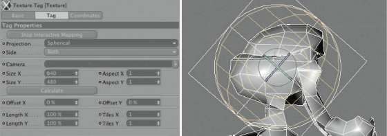
— Figure 4.58: The interactive mapping.
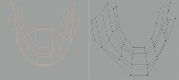
— Figure 4.59: The result of the interactive mapping and the manual unfolding of the UV polygons.
Individually Moving UV Points
The selected areas are now spherically unwrapped but still overlap a bit. This can be manually fixed since the points of UV polygons can be edited as well. Change to USE uv PoiNt edit tool mode and pull apart the points of the projected area of the texture view so that the overlaps disappear. The UV points can be selected by clicking directly on them in the texture view, by selecting them on the object, or by using one of the selection methods in the texture view. Figure 4.59 shows you how the points should be moved. On the right side you can see the half-edited structure of the lower jaw. The right side of these UV polygons wasn’t touched and still contains the unwanted overlaps.
Use the same principle with the polygons of the upper part of the head, as shown in Figure 4.60. The selection includes only the faces visible from the outside and ends at about the HEIGHT of the corner of the mouth. The back of the head, including Trolly’s back, will be unfolded in another step. Here, too, I have used interactive mapping with a spherical projection. These UV polygons might have to be edited at point level in the texture view as well.
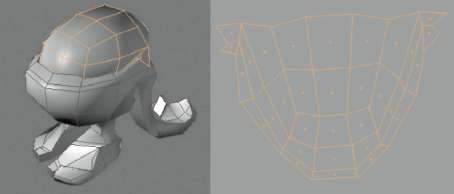
— Figure 4.60: The unfolded area of the head.
As an alternative, you could activate PiN Border PoiNtS and use the APPLY button at uv MAPPiNg>relAX uv. You should still be in USE uv POLYGON edit tool mode and the UV polygons should be selected. This tool automatically rearranges the UV polygons so overlaps disappear. This rearrangement is based on the area defined by the pinned open edge of the outside of the selected UV polygons. For clarity, you should also move these UV faces to the side or above the other UV polygons in the texture view, so a separate “island” of UV faces is created. Use the same principle for the soles of the feet and the back, which you can unwrap with a flat interactive mapping. The polygons on the inside of the mouth can also be unwrapped this way, as well as those of the gum and the lower mouth cavity.
Automatic Unfolding
By using the technique of interactive mapping with the correction of the UV points, every object can be cleanly unfolded. In some cases, though, this can become quite time consuming, especially when the object contains a large number of points or is shaped irregularly. For these instances, there are special unfolding algorithms available that can be found in the relAX uv section. We talked about them before in reference to automatically removing overlapping faces. Additional options allow simultaneous disconnecting of UV polygons for the unfolding of otherwise cylindrically aligned polygons to a flat plane. This is often used for the arms and legs of a character.
Besides the necessary selection of the polygons, the course of the cut for the automatic unfolding has to be specified as well in USE edge tool mode. Figure 4.61 shows such a selection for the example of the arm. In our case I made the cut along the side of the shoulder and followed the natural course of the polygons down to and around the finger tips. Generally, such cuts are made in less visible places, since a texture offset might be obvious there.
First we will work the same way as before. Select the polygons of an arm—the edge selection will not be deactivated—and then switch to USE uv POLYGON edit tool mode. Use the iNterACtive MAPPiNg with a cylindrical projection, as shown in Figure 4.62, and adjust it to the position of the arm.
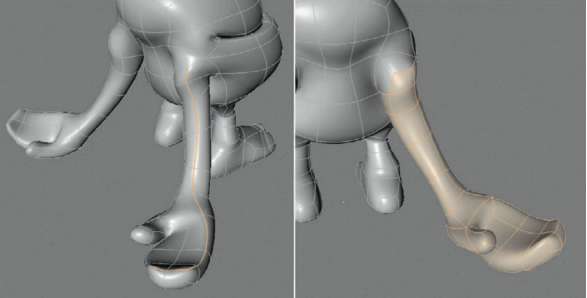
— Figure 4.61: Preparation for the unfolding of the arms and hands.
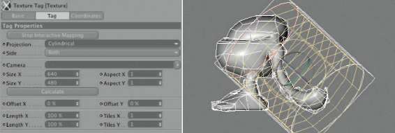
— Figure 4.62: Interactive projection of an arm.
After finishing the interactive mapping, change to the relAX uv category of the uv MAPPiNg section. Everything there should be deactivated except for the Cut SeleCted edgeS option. The selected edges will turn to open edges at the selected faces, and the UV coordinates can be unwrapped after clicking on the APPLY button. As an alternative, selection tags could be used, which are pulled into the fields under the options. Besides the edge selection, point selections can also be generated that are used to fix parts of the surface. The UV coordinates are then unwrapped based on these fixed points.
There are two unfolding methods available: lSCM and the newer ABF. The latter is slower, but better suited for organic objects and the UV faces are straighter. In this case, though, both modes, which can be switched just above the APPLY button, create the same good result. Figure 4.63 shows the outcome. You can see the only weak spot, indicated by the small black circle. BULGEs on the surface often become very small, which is the case with the thumb of our model. Therefore, you should unwrap it manually and create a new edge selection for it.
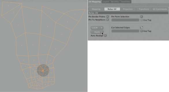
— Figure 4.63: After relaxing and opening the arm polygons.
The same steps can be used for the legs. After the whole character is unwrapped, in one way or another, the separate UV face islands have to be placed, as optimized as possible, inside the standard tile within the texture view. In order to efficiently use the resolution of the texture, no space should be wasted. Lots of information and workshops for the creation of game characters or models can be found on the Internet. In these resources the focus is mainly on the optimal use of textures for reasons of memory management and performance increase. Figure 4.64 shows an example of my arrangement of these UV faces. Connected islands can easily be selected by clicking on one face and choosing SELECTION geoMetrY>SeleCt CONNECTed. Use the common tools for moving, rotating, and scaling to move and adjust the islands to the desired spot in the texture view.
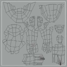
— Figure 4.64: The complete unfolded character.
Controlling the UV Unwrapping
The UV polygons are now unwrapped onto a flat plane and a texture can be optimally placed onto them. This doesn’t guarantee a distortion-free display of the texture on the object, though, since the straightening of the UV faces doesn’t mean that the size ratio of the UV polygons is identical to that of the geometry polygons. This is best checked visually by using an even pattern as the texture. A good texture to use is the CheCkerBoArd shader, found in the SurFACeS group. The number of squares can be set in the dialog of the shader. When you use the same number of squares for both the U and V directions, the result is a uniform checkerboard pattern. This shader can then be loaded into the COLOR channel of our character. Figure 4.65 shows this effect on the left side. You can clearly see the areas of the character that have an irregular projection. Especially noticeable is the area of the lower lip, contrary to the region beneath, which has too high of a resolution. Here the UV polygons have to be moved closer together so the lips take up less space. After this correction, the checkerboard pattern looks much more uniform, as displayed on the right of Figure 4.65.
Subsequent Additions to the Rig
Not always is the concept of a rig or a character planned in such detail that a project can be completed WITHOUT subsequent modifications or additions. In our case, I think, after looking at the character, that the missing eyes limit our possibilities for expressing emotions in the animation. How can we expand the character and its rig after the fact?
First, we need additional geometries. We will use two simple CuBe primitives that are placed hovering above the head of the character. Put them onto the same hierarchical plane as the character. This is under the Null object, which itself is subordinated under the HYPERNURBS. The cubes are then smoothed and lose their distinctive shape. We will counteract that by adding subdivisions. I used two additional SEGMENTS each in the X, Y, and Z directions of the cubes. Then I converted both cubes with the (C) key and pulled the center points on the top and bottom apart, as shown in Figure 4.66.
Create a new material and add a New TEXTURE with white color in the COLOR channel, as shown on the right in Figure 4.66. Assign this material to both eyes. The projection of this texture is automatically set to UV mapping. This is not a problem since we work with primitives that are slightly distorted, but otherwise weren’t changed.
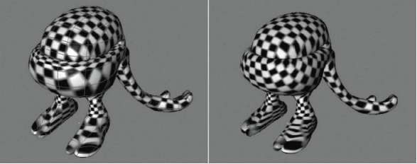
— Figure 4.65: Evaluating and correcting UV coordinates.
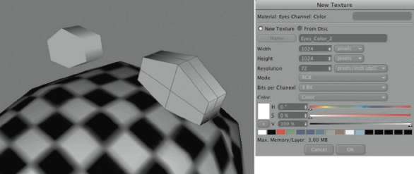
— Figure 4.66: Adding simple cubes as eyes.
Then add two bone objects separately, either from the icon palette or with ChArACter>SoFt ik/BoNeS. Place these bones lengthwise and inside the eyes as shown highlighted in Figure 4.67. These bones should then be integrated into a proper location within the existing bone hierarchy. A good place would be under the head or spine bone, so the eyes can be moved together with the character. Lastly, the bones have to be fixed so their position and rotation are saved. Therefore, select one of the two new bones and select ChArACter>SoFt ik/BoNeS>FiX BoNeS. Do the same with the second bone object.
ADDING WEIGHTINGS MANUALLY TO THE BONE OBJECTS
In order to let the bones know what areas of the character they are supposed to influence, they have to receive weightings. There are two methods to accomplish this. With the conversion of the joints and their weightings, we automatically received bone objects with ClAude BoNet weightings. For the creation of these weightings there is a tool in MOCCA that can be found at ChArACter>SoFt ik/ BoNeS>ClAude BoNet.
The use of this tool is quite simple. First, click on the bone object that you want to weight and then paint the points on the object that are supposed to follow the bone with the ClAude BoNet tool. A colored display on the object gives you feedback about the strength of the weighting. The radius and strength of the weight tool are set in the ATTRIBUTE MANAGER. That way, you can paint the complete eye geometry of an eye, since the eyes should be controlled exclusively by the new bones. Figure 4.68 shows the hierarchy of the new objects and the dialog of the Claude Bonet tool. You can see there as well that I applied additional compositing tags to the eyes. If you don’t have MOCCA available, then you can achieve the same effect with verteX Maps. You can paint them with the BruSh tool from the StruCture menu, with the live selection or by direct assignment to a point selection. Select all points of the left eye and choose SELECTION>Set Vertex Weight. Give the generated Vertex Map a meaningful name in the Attribute Mana ger and then create a Restriction tag for the bone located within this eye. It can be found in the Object Mana ger after a right click on the bone object at CINEMA 4D Vertex Weight. Give the generated Vertex Map a meaningful name in the Attribute Mana ger and then create a Restriction tag for the bone located within this eye. It can be found in the Object Mana ger after a right click on the bone object at CINEMA 4D
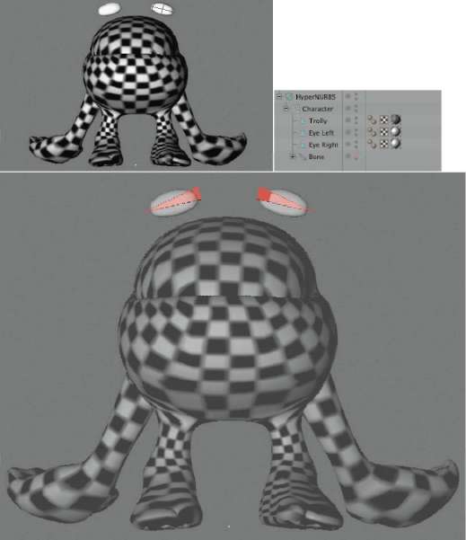
— Figure 4.67: Additional bone objects for the eyes.
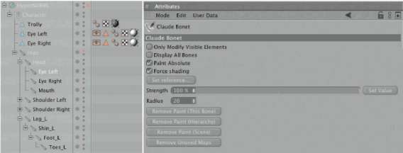
— Figure 4.68: Weighting the new bones.
Painting Objects Directly in BodyPaint 3D
So far we have only unfolded the UV polygons in BodyPaint 3D and therefore prepared them for the texturing. BodyPaint 3D can also be used for the painting of objects. Change to the BP 3d PAiNt layout and activate the new eye material in the MATERIAL MANAGER by clicking away the red cross behind it. Select the brush tool from the icon palette on the left side and set its size and color according to your taste. Then move the mouse pointer across one of the eyes and paint it directly in the editor viewports. Figure 4.69 shows an example of the painting.
After you are done with the painting, take a look at the side and the back of the eye, as shown on the left of Figure 4.70. The painted structure suddenly appears multiple times. It does so because the UV polygons of a cube primitive are placed on top of each other by default. The texture in front is then automatically projected onto the five other sides of the cube. We can correct this easily in our case. Select all faces that are not supposed to show the eye motif. Change to USE uv POLYGON edit tool mode and activate the scale tool. Shrink the selected faces so much that they are placed in the lower left corner of the texture. You can see the corresponding texture view in the middle of Figure 4.70. That way the center of the painted texture remains only at the front faces of the eye. All other faces just show white.
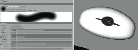
— Figure 4.69: Painting the eye within BodyPaint 3D.
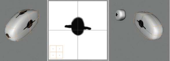
— Figure 4.70: Correcting UV polygons.
TEXTURING THE BODY
Finally, we will concentrate on the texturing of the character’s body. At the beginning of the workshop we made a material and created a new texture in its COLOR channel. This texture was later replaced by the CheCkerBoArd shader, to control the unwrapping of the UV polygons. You can get the original white texture back by opening the shader menu within the channels texture area and looking into the BitMAPS entry. There, you can find a list of all textures used within the scene. You should also be able to find and select the texture with the standard name MAt_COLOR_1, which then replaces the CheCkerBoArd shader.
If this texture was not created or got lost, simply create a new texture with a white color in the COLOR channel, using CreAte New TEXTURE. As previously done with the eye, use a brush with a black color and paint directly on the character the areas that are meant to have another material applied later. I envisioned the body to be covered with toad-like warts, except the feet and the inside surface of the hands. They will receive a different material and should therefore be marked on the character with the black paint. If you can’t paint all areas within the editor viewports, then switch to the texture view and paint there instead, as shown in Figure 4.71. In this texture view you have the advantage of painting directly onto the UV polygons, and you can see their proximity to the other UV islands as well.
When you are happy with the masking of the hands and feet, load this texture into the activated AlPhA channel of the same material. This automatically turns the black painted areas transparent and allows you to see another material underneath. Again, use the BitMAPS entry of the shader menu in the TEXTURE area of the AlPhA channel to load the custom texture.
In the COLOR channel we will now load a prepared toad skin texture. Of course, we could have made the effort to create the texture directly in BodyPaint 3D, but this would go beyond the scope of this workshop. I created this texture by cloning and copying different toad images that I found on the Internet. The coloring can be adjusted within CINEMA 4D using the COLORiZer shader, found in the uppermost level of the shader menu. After the toad skin texture is loaded into this shader, you can exchange the original colors with a custom color gradient and recolor the image. This shader can also be used to turn color images into grayscale or to color grayscale images. Figure 4.72 shows the texture being used and its recoloring in the COLOR channel using the COLORiZer shader. Feel free to be creative with your color choices, or simply use the provided skin texture with its original colors.
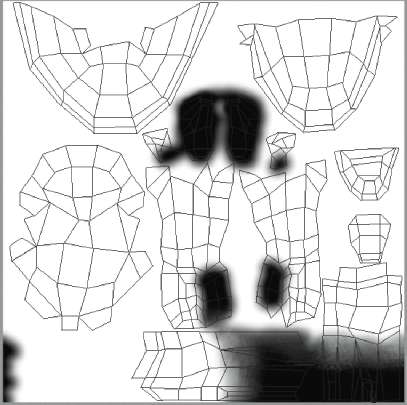
— Figure 4.71: Alpha mask for blending two materials.
I loaded the same skin texture into the BUMP channel of the material and used a negative STRENGTH value, as you can see in Figure 4.73. I would like the warts to be slightly raised. Since the warts are dark in the image, the STRENGTH of the BUMP effect, otherwise based on the brightness of the image, needs to be set to a negative value. Figure 4.73 shows on the right side the use of the painted image in the AlPhA channel.
The highlights can be set any way you want, depending on whether you would like the skin to look dry or wet.
We still need a second material for the hands and feet of the character. The first step is to duplicate the skin material with edit>CoPY and edit>PASte, and to deactivate the AlPhA and BUMP channels of the duplicated material. Remove the skin texture from the COLOR channel as well—use the CleAr command in the shader menu—and use the color slider there to set an appropriate color tone. In my case, I colored the skin with the COLORiZer so the warts have a reddish tint while the base color of the skin appears rather yellowish. I therefore set a corresponding yellow color and applied this material to the character, too.
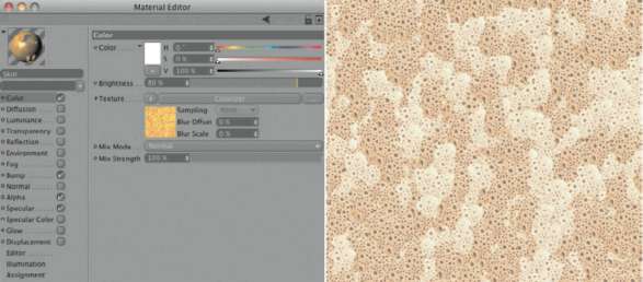
— Figure 4.72: The color texture for the skin.
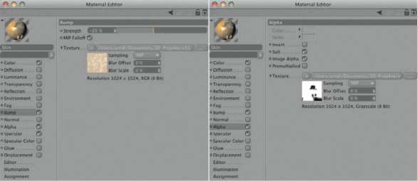
— Figure 4.73: The settings in the BUMP and Alpha channel.
Make sure that the yellow material is placed underneath the skin material, which means put it to the left of the skin material in the OBJECT MANAGER. Only in that way can the yellow material be seen through the alpha areas of the skin. Figure 4.74 shows an example of the finished look of the character.
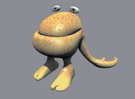
— Figure 4.74: The completed textured character.
BAKING TEXTURES
The baking of a texture is the reduction of the surface properties into a single bitmap. For example, the entire surface coloring, which has been defined by layering several complex shaders, can be reduced to one bitmap. This makes it easier to pass on the textured model to another software. Of course, it is also helpful for use within CINEMA 4D since it reduces the objects’ calculation time. A bitmap can be displayed much faster than one or several shaders that are combined with each other and then rendered. Global illumination, ambient occlusion, and the lighting can be baked as well; even the conversion of material properties is possible. Through baking you can also convert a BUMP map into a normal map. For the baking of textures, first create a BAke TEXTURE tag by right clicking on the textured object in the OBJECT MANAGER. This tag can be found in the CINEMA 4D TAGS list.
Figure 4.75 shows you the parameters available in the tag. In the TAG section of the ATTRIBUTE MANAGER you will find basic settings regarding the file format and file path, as well as settings regarding the size of the texture to be calculated. AutoMAtiC SiZe enables two additional values for the minimum and maximum size that CINEMA 4D uses to calculate the proper resolution. This calculation is based on the pixel size value, which defines the size of the pixel in square meters. This could be helpful for working with certain measurements on a model, such as modeling a plane with a dimension of 200 x 200 meters. This would result in an area of 40,000 m2. When this value is divided by the entry in the pixel size field (the default is 0.5), this turns into 80,000 m2. Since the plane is square, we get the number of pixels in both the X and Y direction by taking the square root. Rounded up, this would be 283 x 283 pixels for the baked texture, as long as this value lies within the minimum and maximum size values.
The anti-aliasing settings in the RENDER SettiNgS have no effect on the baking of textures. A comparable effect can be generated with the SuPerSAMPliNg setting. This setting is deactivated at a value of 0. Higher values activate and increase the edge smoothing, but this also increases the calculation time. The value for the PiXel Border extends the calculation past the boundaries of the UV polygons by the entered value. If CoNtiNue uvS is activated as well, then visible color edges between the UV polygons can be avoided since the color value calculation is then extended past the boundaries of the polygons. The background color is used anywhere in the baked texture where there aren’t any UV polygons.
On the oPtioNS page of the tag dialog, displayed on the right of Figure 4.75, activate the properties of the surface that you want to bake as separate textures. The uppermost settings provide you with additional options. With USE POLYGON SELECTION the baking is restricted to just this selection, evAluAte BUMP takes into consideration effects that depend on normals, and USE CAMerA veCtor includes the current viewing angle to the object, useful for capturing fresnel effects, for example.
Underneath are the options for the properties to be baked. In our case we are only interested in the COLOR of the surface and the AMBieNt oCCluSioN. The latter needs some time for calculation and, through baking, can save us some render time during the animation. AMBieNt oCCluSioN receives its settings from the render settings, and therefore doesn’t need to be applied as a shader within the material. AMBieNt oCCluSioN doesn’t even have to be activated in the render settings.
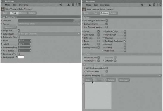
— Figure 4.75: Settings of the Bake Texture tag.
Every activated option for the baking of a surface property enables some additional options below it. For baking the COLOR you can include the influences of lighting, shadows, diffusion, and luminance. We will leave everything deactivated, though. AMBieNt oCCluSioN could be set to calculate the self shadowing only. In addition, the INTENSITY of the AMBieNt oCCluSioN can be converted to weightings for the points of the object and saved as a vertex map. This map could then be interpreted by the verteX Map shader. However, we don’t need that option and will keep it deactivated.
I decided to save the baked texture in Photoshop format and checked the SiNgle FILE option. After clicking on the BAke button, we will receive a file in which we can mix the AMBieNt oCCluSioN with the color of the surface. Don’t be irritated by the small size of the preview window that shows the progress of the calculation. It shows the result of only one baked channel, but all checked properties are saved. Figure 4.76 shows a possible result. Clearly visible is the darkening by AMBieNt oCCluSioN between the lips, the base of the arms, and of course the mouth cavity.
With the baking of textures, it is very important to check the surface normals. They should uniformly point outward so no irregularities occur during the calculation of AMBieNt oCCluSioN or lighting effects. Load this baked texture into the COLOR channel of the skin texture and deactivate the Alpha channel of the material. The second, yellow material for the hands and feet can be removed entirely from the character. These colors are now baked within the texture. If you prefer, bake the BUMP of the character to a normal map and use it in the NorMAl channel of the material. This makes it easier to later export the character to a game engine. It is important in this case to calculate the normals within the veCtor space. That way, these normal maps can be interpreted in other programs.
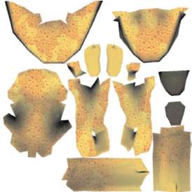
— Figure 4.76: The finished combination of baked Ambient Occlusion and surface color.
This concludes the modeling, rigging, and texturing, and we can start with the animation.
Animating the Character
The process for animating a character is generally identical to the animation of a rigid object. The difference is that with a character several objects have to be fixed with keyframes. Basically, it would be enough to animate and set keyframes of the external help objects, but, depending on the complexity of the movements, it might become necessary to animate single bones.
The Selection Object
Instead of having to manually select each of the objects for setting keyframes, we can use the SELECTION OBJECT. This object saves multiple objects and can be animated with keyframes. First, select all objects that are primarily used for the animation of the character. I selected the external foot handlers, the root bone of the character, and all bone objects of the legs. The latter doesn’t need to be added, since they are covered by the external handlers, but I already have the planned export of the character in mind and the use of external handlers and inverse kinematics will not be possible.
After the selection of these objects, choose SELECTION Filter>CreAte SELECTION OBJECT in the SELECTION menu. The generated object provides a list in the ATTRIBUTE MANAGER, which is shown in Figure 4.77. The listed objects can be selected anytime with the reStore SELECTION button. More objects can be added to the list via drag and drop from the OBJECT MANAGER or removed from the list by right clicking on the object and using reMOVE. To be able to find it again when keyframes are set, give the SELECTION OBJECT a meaningful name.
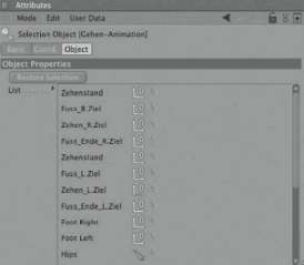
— Figure 4.77: The Selection object.
The Visual Selector
During the animation we will often have to select and manipulate certain objects, such as the foot handlers or single bones. Since these are always the same objects, we could use some help to accelerate the selection process. The Visual Selector can be used for that purpose. A random background picture can be added to it, and links to objects within the scene can be placed onto this image.
In the first step, render an image that shows the character in a neutral pose so all body parts can be seen. Then assign the viSuAl SeleCtor to any one of the objects in the scene with a right click and by choosing ChArACter TAGS>viSuAl SeleCtor. In the settings of the tag in the ATTRIBUTE MANAGER you can determine a file path to the background image. You could also drag and drop an image, from your finder or file browser, directly into the empty window of the viSuAl SeleCtor, which opens up after a double click onto its tag.
Figure 4.78 shows an example of using the front view of our character as the background image in the viSuAl SeleCtor. The additional symbols you see there were created by drag and drop of the Null objects from the OBJECT MANAGER directly into the viSuAl SeleCtor. The generated links can then be pulled to the desired spot on the background image. A click on these symbols selects the corresponding object in the OBJECT MANAGER to which it is linked.
Accidentally placed links can be DELETEd anytime by pulling them out of the viSuAl SeleCtor window. More settings can be found in the TAG part of the viSuAl SeleCtor, as shown in Figure 4.79. There, you can see the links that belong to the symbols. These links can be changed there as well. In the ACtioN menu below, a tool can be assigned to each of the hotspots. This tool is then automatically activated by clicking on an icon in the viSuAl SeleCtor. The common tools are move, rotate, and scale. In addition, normal commands and functions can be connected with the hotspots when the CoMMANd action is active. The desired action is assigned by entering the CoMMANd id.
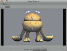
— Figure 4.78: Interface of the Visual Selector.
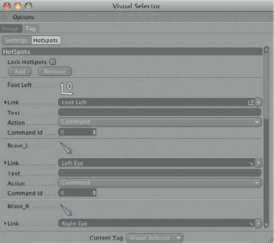
— Figure 4.79: Settings for the links and hot spots of the Visual Selector.
The ID numbers of all functions and commands can be found at wiNdow>lAYout> CoMMANd MANAGER. It contains a complete listing of all CINEMA 4D commands that can be sorted with the use of the search field. A click onto one of the commands in the list shows its ID as well as existing keyboard shortcuts for executing the command. That way you can use individual shortcuts as well.
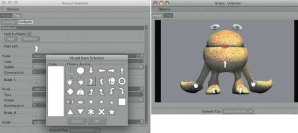
— Figure 4.80: The use of individual hotspots.
The look of the hotspot icons is set by the viSuAl SeleCtor and based on the type of linked objects. We have a selection of symbols to choose from, in a list of preset icons which opened after clicking on the icon of a hotspot as shown in Figure 4.80. The coloring of the icons can be altered as well. The right side of the figure shows an example of the individual composition of the applied links.
Creating a Walk Cycle
With animations of characters, the term wAlk CYCle is often used. It is a complete walk movement of the character that can be turned into a walk or run by automatically repeating it multiple times. That way we have to use only a few keyframes to allow the character to walk a certain distance. Additional movements, like facial expressions or individual arm movements, can then be added to make the animation appear less linear.
The timing is very important during an animation. The wrong approach is to set too many keyframes in the beginning. First comes the length of the animation, then the speed has to be determined. This is also called BloCkiNg the animation. The goal is to depict the animation with just a few core poses. The time between the poses should be set in such a way that the correct speed of the character movement is achieved. With a walk movement, this can be set with three poses, where two of these poses are identical. The first pose shows the character, for example, with the left foot forward and the right foot in the back. The second pose shows an opposite step, which means the right foot is now in front and the left foot in the back. Figure 4.81 shows these two poses from different perspectives. The upper row shows the pose from frame 0 of the animation. It is created by moving and rotating the handlers at the feet, and by the moving and rotation of the root bone to indicate a shifting of the character’s weight.
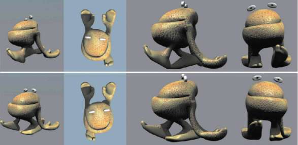
— Figure 4.81: Key poses of the walk cycle.

— Figure 4.82: Selecting the previously created Selection object for the keyframe recording.
When you are happy with the pose, create keyframes for the rotation and movement of the objects saved within the SELECTION OBJECT. Make sure that the SELECTION OBJECT is selected for the keyframe recording, as shown in Figure 4.82. Then move the timeslider to the frame when the character completes one whole step. I determined that to be frame 29. Depending on your desired step speed and the planned frame rate of the animation, time lengths other than the one I used are possible.
SETTING THE FRAME RATE
I plan to output the animation with a frame rate of 25 frames per second and have already set this in the project settings. You can find them in the edit menu of CINEMA 4D under ProjeCt SettiNgS. The settings regarding the frame rate should always be checked before the animation is started and adjusted to the desired output media. Belated changes of the frame rate are possible, but create more work because all previously set keyframes would have to be moved or scaled.
At the chosen endpoint of the walk movement, create again keyframes for the SELECTION OBJECT. The time frame is now set for a left/right step of the character and we can move to the center of the time frame. In my animation this would be frame 14. At this frame we need to modify the pose of the character so that it shows the exact mirrored opposite, as can be seen in the lower row of Figure 4.81. After these keyframes are set, the blocking of the step movement is finished. The extreme poses as well as the time frame for a complete cycle are now defined. Figure 4.83 shows how the animation looks in the tiMeliNe, which can be found in the wiNdow menu of CINEMA 4D.

— Figure 4.83: The three key poses of the walk cycle.
OPTIMIZING THE DISPLAY IN THE TIMELINE
For more clarity in the timeline, I like to turn off all objects, materials, and any additional information that have nothing to do with the animation. Click on the eye symbol in the title bar of the timeline. This causes a list to appear, containing several elements that can be displayed in the timeline, such as the RENDER SettiNgS or the materials. A click on the eye symbol next to these elements turns them invisible in the timeline. This is no loss for us, since we didn’t want to animate these elements in the first place, and it gives us more space and a less cluttered look. In addition, you can use the magnifying glass symbol to control which objects or settings can be found by the search function and which ones should be ignored. This can be helpful with complex scenes containing many animated objects. The search function itself is hidden behind the magnifying glass in the title bar of the timeline.
CYCLICAL PLAYBACK OF THE ANIMATION
In order to check the speed of the step, play the movement of the character in a looped animation. In the ANiMAtioN menu of CINEMA 4D, set the PlAY MODE to Preview rANge and CYCle. Then reduce the preview range by moving the end arrows in the pow-erslider to an area between frame 0 and frame 28. The necessary steps are shown in Figure 4.84. Frame 29 of the animation looks exactly like the state of the character in frame 0 and can therefore be skipped. Otherwise, there would be a hesitation at the end of a step, since this pose appears twice.
Because so far we are working with only three keyframes, it is still easy to adjust the speed of the steps. Simply select and move the keyframes, at frame 14 and 29 in the main track of the timeline. Once you are pleased with the timing of the steps, move on to the DETAILS. You should then concentrate on the rolling motion of the feet and the shift in weight.

— Figure 4.84: Necessary settings for the cyclic playback of a certain section of the animation.
FINISHING THE ANIMATION
When the animation is played, you will certainly notice some movement phases that are not the way they should be. Perhaps the toes sink into the imaginary floor, or the movement is simply too monotone. Correct this with additional keyframes for single parts of the character, like for the external handlers. Keyframes don’t have to be set for all objects within the SELECTION OBJECT, though. Deactivate this recording mode by selecting ACtive OBJECTS in the menu, shown in Figure 4.82. The following keyframe recordings then only pertain to the currently active object. Figure 4.85 gives you a hint of the desired course of the animation. The images in this figure were recorded with a gap of two images in between. The sequence starts on the top left with frame 0 and ends on the top right with the pose from frame 6. The row underneath shows the same poses seen from a side view.
Figure 4.86 continues this image sequence, from frame 8 to frame 14. This completes a whole sequence of switching feet from left to right. The subsequent poses, up to reaching the starting pose, are equal to the sequences shown in the two figures, only they run the opposite way. The random step of two images in these sequences doesn’t mean, though, that you have to set keyframes for every second frame. I only selected this time range to show you an almost continuous display of the movement. Most likely you will use fewer keyframes to animate a similar movement.
Don’t forget to vary the arm movement as well. Adjust the distance between the hands and the body, based on the pose of the body during the walk, WITHOUT disconnecting the hands from the virtual floor. These keyframes should be created for the external handlers as well as for the bones that are controlled by them. In this case, these are the bone hierarchies starting at the shoulder. Save them, together with the hand handlers, in a new SELECTION OBJECT so the keyframes for these objects are automatically generated. You should first generate three to four keyframes for the external handlers of the arms until their animation looks right. Then jump back to the beginning of the animation and fix the existing animation of the arms with additional keyframes in even steps. You could record rotation keyframes for the arms at every two frames, to capture with keyframes the dynamic behavior controlled by the MOCCA IK.
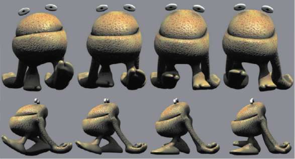
— Figure 4.85: Image sequence of the walk cycle.
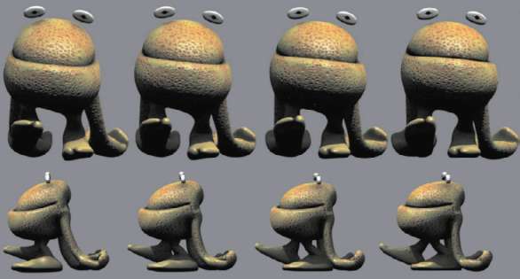
— Figure 4.86: The second half of the image sequence.
The reason for not that many keyframes being needed for the legs and the body is that we don’t save their poses with keyframes alone, but can also influence the sections in between the keyframes with curves and tangents. Figure 4.87 shows in the upper part my keyframes for a complete walking sequence. Below you can see as an example the display of the stomach bone movement in both the X and Z directions. For this view of the function curves of an animation, you have to change to the corresponding mode, as indicated by the arrow in the figure.
A Y movement, the up and down moving of the stomach, does not occur. The character instead falls slightly forward as soon as the front foot has contact with the floor. At the same time, the lateral shift along the X axis causes a weight shift to the front foot. The maximum of this lateral movement is always reached at the time when the rear foot just starts to depart the floor and begins to move forward. As long as you use the standard Spline interpolation for the keyframes, you can control the course of these curves with tangents in the display of the function curves, WITHOUT having to set additional keyframes.
Onion Skinning/Ghosting
During the refinement and evaluation of animations, the constant comparison of the current pose with the previous and following one is important. Therefore, the playback of the animation in real time, in my case with 25 frames per second, is important. This cannot always be achieved, though, when complex animations or high-resolution objects have to be displayed. In these cases, the oNioN SkiNNiNg can be a big help since it depicts past and future states of an animated object within one image. Apply a diSPlAY tag to the animated object. This tag can be found in the context menu in the CINEMA 4D TAGS, after a right click on the object in the OBJECT MANAGER.
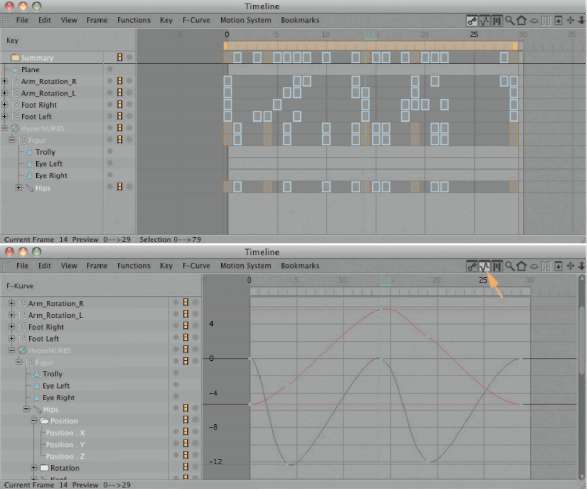
— Figure 4.87: Adjusting the keyframe interpolation.
You can activate this effect in the ghoStiNg settings. Several display modes offer different views in the editor. Figure 4.88 shows an example. The movement phases of objects can be shown as a track curve, as single points, or as the whole object surface. With deformations there are certain restrictions, since the animation has to be saved first in a cache with the diSPlAY tag. You can find the corresponding function in the lower part of the dialog. By using the CAlCulAte CAChe button, you initiate the saving of the animation. Afterward, activate the USE CAChe option to read the cache.
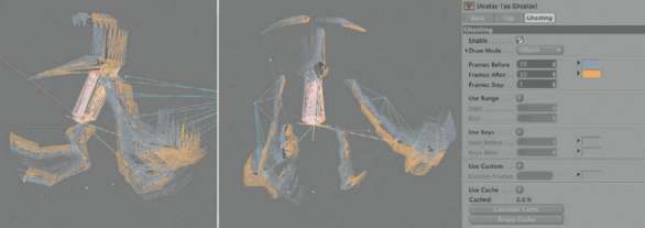
— Figure 4.88: Ghosting effect of the animated bone objects.
In the case of our bones this is not necessary. Just put the tag onto the uppermost bone of the hierarchy and activate the drAw MODE called OBJECT. With the FRAMES BeFore and FRAME AFter settings you can define the number of images, before and after the current point in time, which should be captured by the ghosting. The FRAMES SteP value defines the manner in which they are counted. A value of two always skips the display of one image in between. When the display in the oNioN SkiNNiNg layering is supposed to show only a certain range of images, activate USE rANge and define the start and end frames.
The ghosting overlay is automatically colored. As a standard, all past movement phases appear blue and the following poses look orange, but these colors can be changed. Also, the poses that were fixed with keyframes can be highlighted with a color; this is achieved by using USE keYS. This causes a blend of the colors behind the keYS BeFore and keYS AFter fields. These values define the time frame of the color blending relative to a keyframe. This display mode is only available in OBJECT, AXiS, or PoiNt mode, though.
Individual image ranges can be defined as well. Activate the USE CuStoM option, which enables an entry field for numbers, and enter numbers separated by commas or larger sections, like 10–35. Combinations are also possible, like 10, 15, 20, 30–50. Figure 4.88 shows the ghosting effect with simultaneously deactivated geometries in the editor.
WORKING WITH MOTION CLIPS
The entire animation is actually captured twice in keyframes, once with the external handlers and again with the keyframes and the bones themselves. Theoretically, this means that we can entirely forego the evaluation of the external elements. In order to check this, select all MoCCA ik tags behind the arm bones and, within the tags, deactivate the USE ik option. Do the same with the ik tags of the legs. Figure 4.89 shows this step. There shouldn’t be any differences in the movement when the animation is played, as long as enough keyframes were used to fix the bones.
Only the type of interpolation between the keyframes could still cause small differences in the animation. This is often caused by the so-called overshooting of the function curves at the standard SPliNe interpolation. This sort of interpolation has the advantage that automatically soft blends between the keyframe values are calculated. But this could also cause an overshoot of the interpolation curve out of the desired value range, for example, when two neighboring keyframes with identical values are used. To avoid this, either deactivate the Auto tANgeNtS option in the keyframes to manually control the tangents, or activate the ClAMP option of the keyframes, as shown in Figure 4.90. This automatically aligns the tangents horizontally at the interpolation curves between identical keyframe values and prevents the overshooting. This completes the animation of one step and we can concentrate on the repetition of the animation and the varying of the walk movement.

— Figure 4.89: Deactivating inverse kinematics.
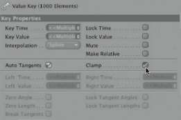
— Figure 4.90: Cutting overshooting interpolation curves.
For this purpose the new MotioN CliP and MotioN lAYer can be used. These are links to a keyframe animation similar to an instance of an object. The original animation remains unchanged in the following steps. Such a
MotioN CliP is advantageous in that we can copy, move, and scale the animation afterward. The most interesting feature of these MotioN CliPS is the ability to combine several of these clips with each other. Clips can be layered and mixed, as well as cross-faded into one another. The animation system with clips is very similar to working with video clips in a video editing program.
Creating a Motion Clip
The creation of a MotioN CliP is very easy. First, select the uppermost object of the animated hierarchy, or if just one object is animated, select that single object, and then choose Add MotioN CliP in the ANiMAtioN menu of CINEMA 4D. In our case select the uppermost bone of the hierarchy. Then a dialog like the one in Figure 4.91 opens. First give the clip a fitting SourCe NAMe like Walk Cycle. This is important so that there won’t be confusion later when multiple clips are used. The STARt and eNd values define the frame range of the animation of the selected object hierarchy that is supposed to be loaded into the clip. We will enter the same range that we used in the preview range: frame 0 up to frame 28. The CreAte MotioN CliP option initiates the creation of the motion clip, and BAke eXPreSSioNS also incorporates the effect of expressions onto the keyframe animation. reMOVE iNCluded ANiMAtioN FroM origiNAl OBJECT would DELETE, in our case, the keyframes of the bone hierarchy. The animation would then only exist as a MotioN CliP. The CreAte PiCtureS option is a more visual preference since it renders little icons for the first and last image of the clip that display the state of the hierarchy at that moment. These images will then be shown in the MotioN MODE of the tiMeliNe.
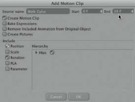
— Figure 4.91: Creating a motion clip.
Which kind of keyframe is added to the MotioN CliP is defined with the options in the lower part of the dialog. Here, different combinations of PoSitioN, SCAle, rotAtioN, PlA, and PArAMeter keyframes can be activated. The hierarchy window also puts together a preview of the elements that will be added to the MotioN CliP. Single objects or branches of the hierarchy can be skipped at the creation of the MotioN CliP by deactivating the little checkmark behind the name. In our case we will leave everything active. You can use the settings in Figure 4.91 as a guide. We will not DELETE the animation of the original objects and will save PoSitioN and rotAtioN keyframes in the MotioN CliP.
The Motion System Tag
A soon as a MotioN CliP is generated, a MotioN SYSteM tag is added behind the selected object, as shown in Figure 4.92. The option Show ghoSt can be used to blend in additional ghost overlays of the animation or to display the summary path in the editor with the Show SuMMArY PAth option. The following buttons are used for the creation and managing of additional layers, so-called MotioN lAYerS. These are also automatically generated when several Movie CliPS are created for the same object hierarchy. As a standard, all MotioN CliPS are loaded into the deFAult lAYer. Manually created layers can be mixed in the dialog of the MotioN SYSteM tag and used in a relative or absolute manner.
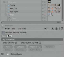
— Figure 4.92: The Motion System tag.
The Motion System of the Timeline
Within the tiMeliNe you already know the display modes of keyframes and function curves. An additional icon in the title bar allows the switch to MotioN MODE. There, the additional display of MotioN SourCeS can be activated. The necessary icons are highlighted in Figure 4.93. The modes of the tiMeliNe can also be switched in the view menu. When the MotioN CliPS are activated as well, you see their listing on the left side of the tiMeliNe and see their saved hierarchy, as well as the length of the Movie CliP. To the right are the MotioN lAYerS. The percentage value behind the layer name can be animated with the circle in front of it; it controls the opacity and the influence of the layer on the overall animation. On the right is the key area with the visual display of the clips and layers. Figure 4.93 shows these three sections of the complete MotioN MODE. The additional information in the colored section of the MotioN CliP can be controlled with the MotioN SYSteM>MotioN view menu in the tiMeliNe. There, the start and end times, as well as trimmed sections of time and the looptime, can be turned on. As previously mentioned, the influence of the layers can be animated with percentage values. The generated keyframes, including their interpolation curves, can either be shown in the colored areas of the clips or displayed separately underneath.
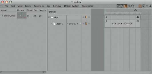
— Figure 4.93: Display of the Motion Clip in the timeline.
A click on the colored part of a MotioN lAYer shows its parameters in the ATTRIBUTE MANAGER. Figure 4.94 shows this dialog. Besides the editable name and the color of the clip, the source of the clip itself can be seen and exchanged via drag and drop. With the loCked option, changes to the clip are no longer possible. Besides the set start and end times, which are determined when the clip is created, the looPS function is especially interesting since it can be used to make the clip perform a number of repetitions. relAtive looP adjusts the repeats so the values at the beginning and end are equalized. This makes it possible to climb stairs when only the climb to the first step has been animated. Using the relative loop, this animation can then be continued. Several of these clips can be copied and played at different times during the animation. When the clips are arranged in a manner that creates overlaps, the animation of the clips is blended. The length of the blending is defined with BleNd STARt and BleNd eNd. This area can be edited directly in the timeline as well. The blending itself can be defined in the BleNdiNg menu. The so-called ease curves create a natural-looking transition between the clips. Depending on the eASe iN and eASe out settings, this transition starts slowly and then speeds up or does the opposite. The eASY eASe setting creates a slow blending in and out of the clips. This is similar to the normal spline interpolation between keyframes. A separate SPliNe mode is also available that makes it possible to define an individual curve. The curve that runs from top left to bottom right by default causes a linear blending. Control points, which can be added to the curve by clicking on it, allow you to shape a different behavior curve.
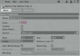
— Figure 4.94: Settings of a Motion Layer.
Back in the keYFRAME mode of the tiMeliNe, you can see that a copy of the objects in the MotioN CliP was created. Figure 4.95 shows that. In the OBJECT MANAGER everything stays the same, though; no new objects were created. Depending on the setting of the reMOVE iNCluded ANiMAtioN FroM origiNAl OBJECT option when the MotioN CliP is created, the keyframes are either gone from the original objects or still available in addition to the keyframes of the MotioN CliP.
Mixing Motion Clips
The strengths of MotioN CliPS can only be used to their fullest extent when several separate clips are combined with each other. Therefore, create another clip, but this time only for the head bone and the subordinated bone objects. Depending on your walk cycle animation, this bone might already have some keyframes, which cause the mouth to open and close slightly during walking so this area doesn’t appear too static. If you don’t have such keyframes, you could create them now. An overlap of bone object keyframes and MotioN CliP keyframes can be excluded during the recording of new keyframes for the bone hierarchy by using the MutiNg symbol behind the MotioN CliP of the walk cycle. This filmstrip symbol activates or deactivates the evaluation of sequences in the tiMeliNe. The term Mute is used in CINEMA 4D for this function. An animation can be muted for a period of time that way.
If several keyframes are created for the movement of the head or mouth, select the head bone and choose ANiMAtioN>Add MotioN CliP. This time you can activate reMOVE iNCluded ANiMAtioN FroM origiNAl OBJECT. We will only need rotAtioN keyframes for the MotioN CliP, since the local positions of the head bone most likely haven’t been changed during the animation. Figure 4.96 shows a snapshot of this step.
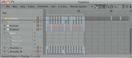
— Figure 4.95: Display of the Motion Clip in keyframe mode.
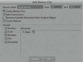
— Figure 4.96: Creating a Motion Clip of the head movement.
Since the keyframes of the head animation were DELETEd at the original bone objects, we can now create a second mouth and head animation. First, switch the new clip for the head hierarchy to mute. After this new head animation is complete, save it as MotioN CliP and DELETE the keyframes again at the original. Figure 4.97 shows the result. We now have a clip for the entire animation of the character bones and two clips with different head animations. The keyframes of the character can now all be DELETEd, even the keyframes for the arms and legs. These animations are already included in the clips. The mute setting of the MotioN CliPS can be deactivated again.
Figure 4.98 shows how the mixing of different clips in the tiMeliNe could look. At the top you can see the clip of the actual walk cycle. Independent of it, a new group for the head animations was created. This group is automatically created since the head clips pertain to different objects. The upper layer in this group, here named Layer 2, contains the normal animation of the head during the walk. This layer has the same length as the walk cycle clip and can go through the same number of loops to stay synchronized.
The head animation, named Layer 0, contains more extreme mouth and head animations that are supposed to loosen up the monotony of the animation. This animation is slightly longer than a normal step of the character and isn’t repeated. Instead, I created a copy of this MotioN lAYer with a (Ctrl) drag and drop directly into the timeline, and slightly moved it. The standard mode Mixing causes a mix of this animation with the layer above, which contains the normal head movement during the walk.
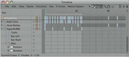
— Figure 4.97: Different Motion Clips in the timeline.
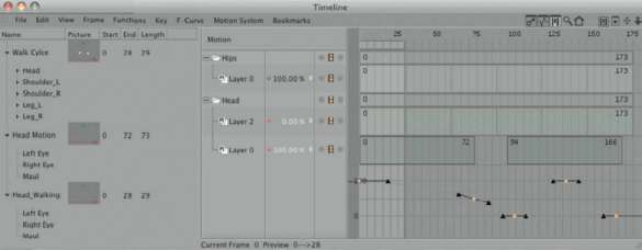
— Figure 4.98: Mixing different clips and layers.
As you can see in the lower part of Figure 4.98, I created an interpolation curve by animating the layer strength, which can be controlled with tangents, like a function curve. The use of the (Ctrl) button, as well as clicking on the keyframe recording circle in front of the layer value, is only necessary with the setting of the first keyframe. Afterward, the simple change of this value generates a keyframe for the strength of the layer.
This is an additional possibility for partly mixing layers and for varying the INTENSITY of their animation. That way you can add many additional animations as clips and layers and create many variations with just a few initial animations. The whole process can be compared to the morphing of objects by mixing different shapes.
Let us take a quick look at the MotioN lAYer of the walk cycle. Click on its colored part in the tiMeliNe to show the parameters of this sequence in the ATTRIBUTE MANAGER. In the hierArChY section there will be an overview of the objects and animations saved within the clip. Because we took out the animations of the head as separate clips and layers, the corresponding elements can now be deactivated. Open the hierarchy in the source view, as shown in Figure 4.99, and remove the checkmarks behind the bone objects of the head hierarchy. The keyframes of these objects that may still exist in this clip are then simply ignored.
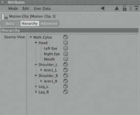
— Figure 4.99: Deactivating single parts of the hierarchy.
Infuencing the Pivot of the Animation
You most likely have noticed that we made the character walk on the same spot this whole time. This is easier to deal with than simulating an additional forward movement. It would also become more difficult, for example, to have the character walk around a curve. In order to change the position of the animated object in 3D space WITHOUT having to change the existing keyframes, we need to use the Pivot object.
You can create it by clicking on the colored area of a motion layer in the timeline and switching to the AdvANCed section in the ATTRIBUTE MANAGER. Figure 4.100 shows the dialog on the left. With the CreAte Pivot or CreAte keYFRAME Pivot button, you can create an object that is similar to a Null object. By moving or rotating this Pivot object, the animation of the motion layer can be moved or oriented differently. This Pivot object can also be animated with keyframes and therefore could generate a forward movement of the character WITHOUT having to change the keyframes of the motion clip.
It is not so important whether you create the Pivot object with or WITHOUT keyframes. They can always be manually added later. The handling of the Pivot object is not much different from any other normal object. Only the display in the editor, contrary to the Null object, can be changed. This can be seen on the right of Figure 4.100. With the RADIUS value entered directly on the Pivot object, its size can be changed.
Besides the variation and addition of animations, the MotioN CliP can be used for a complete blend of multiple clips. I will add two more motion sequences to the original scene with the walk cycle, a so-called idle animation and a jump. An idle animation contains a minimum of body movements, such as those that are used in video games when the game character doesn’t receive input from the player. This could be a simple shift of weight from one foot to the other or a look around. The jump animation expands the motion range of the character, for example, to jump over an obstacle.
Figure 4.101 shows how simply such an idle animation can be structured. The character just bends its knees a bit by moving the root bone slightly downward. This has to be done in the scene where the external help objects and the IK tags are still active.
Your jump animation could look similar to that shown in Figure 4.102—just use your creativity. I put the three different animations directly into the timeline, one after the other. This idle animation lasts, in my scene, from frame 0 to frame 24. At frame 25 the jump starts, and it returns to its start position again at frame 49. The walk cycle is placed between frame 50 and frame 79. Figure 4.103 shows these areas highlighted by their selection.
As before, create different MotioN CliPS for these three areas. The keyframes of the original hierarchy can be left alone. You can simply set them to mute by deactivating the filmstrip behind the root bone in the timeline. In MotioN MODE, arrange the clips to your liking and repeat the walk cycle multiple times. Figure 4.104 shows the status right after creating the three clips.
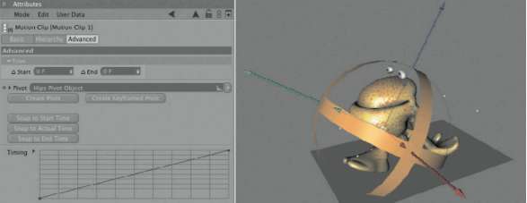
— Figure 4.100: The Pivot object.
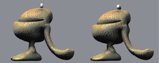
— Figure 4.101: Simple idle animation.
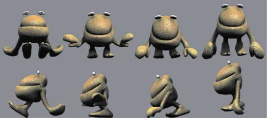
— Figure 4.102: The jump animation in its motion phases.
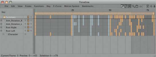
— Figure 4.103: The keyframes for the idle, jump, and walk animation in the timeline.
Trimming Clips
Make sure that the clips end with the same pose with which they started. If you included the whole frame range of the animation when the clips were created, click on the colored area of each layer, and for eNd increase the value to 1 in the ATTRIBUTE MANAGER. You can find this value in the triM settings of the AdvANCed section. The layer then ends one frame before the motion clip is completed and doesn’t show the last keyframe. This could also be done with the STARt value in the beginning of the clip. This way you can take from each layer exactly the part you want to use in the animation.
Automatically Blending Clips
Arrange and mix the motion layers in the way they should be played. You can do this in the same way the second head animation was added. This can be made even easier with the MAke trANSitioN function in the MotioN SysteM menu of the tiMeliNe. When you create a connection between two motion layers with this tool, by pulling the mouse directly in the timeline, an eASY eASe blending between the movements is automatically generated.
Figure 4.105 shows this procedure on the left side. The arrow indicates the pulling of the tool from one layer to the next. After the mouse pointer is released, a blending is created, as shown on the right of the same figure. Since the walk cycle is repeated several times, the tool automatically blends the jump out at the end of its run and again leaves the control of the character to the walk cycle.

— Figure 4.104: The display of the three clips in the timeline.

— Figure 4.105: Automatic creation of a transition between the motion layers.
Now you are familiar with all the important techniques and functions of the MotioN CliPS and their layers. This provides you with a powerful tool for the creation of complex animations that can quite easily be changed and varied later. The possibility of animating the Pivot point separately makes it easy to use motion clips multiple times within a scene and to utilize the created animations in other scenes as well.
Game Development
Concluding this subject of character animation, I would like to demonstrate the use of animated characters in external game development. We already have all the parts together. The character is modeled and has a bone rig. The textures were simplified by baking them and the desired animations exist as separate blocks. Most game engines are able to exchange all necessary information with the FBX format, which can be read as well as written by CINEMA 4D. For this trip into game development, I used the software Unity 3D (www.unity3d.com). It has the additional advantage of a direct connection to CINEMA 4D with its own plug-in.
This software is currently only available for Apple Macintosh computers, yet has very powerful possibilities. It can be used to save the generated applications for Windows PCs as well as for Apple computers. Additional options contain the development for Nintendo Wii, for the iPhone, or as a browser game. As for the exchange and control of data, there aren’t any big differences from other programs. Many of the steps can be transferred to other game engines as well, in case you wish to enter the interesting field of interactive 3D graphics. This is interesting not only for games, but also for information applications or architecture walkthroughs.
Unity 3D creates, at the start of a new project, a so-called ASSetS folder in which you should save all objects, materials, and animations that are used within the project. These elements automatically appear in the ProjeCt window of Unity 3D and can be pulled into the game scene from there. First, we tell Unity 3D that the animation in the scene is supposed to be split into three parts. These can be separated from each other by a number of frames. Here, mainly MotioN CliPS are generated. As you can see in Figure 4.106, I again skipped the last image of the animation so there is no hesitation at the end of the animation.
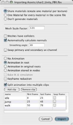
— Figure 4.106: Importing the scene into Unity 3D.
The individually given names of the clips are later used in the script language to gain access to the single animations. First, we determine the standard behavior of the character. Pull the character from the ProjeCt window into the hierArChY view. This is similar to the OBJECT MANAGER in CINEMA 4D and lists all objects in the scene. The iNSPeCtor window works like the ATTRIBUTE ManAger and shows parameters, such as the current position in 3D space or general settings of the selected object. In the ANiMAtioN section the three loaded clips of our character appear. Figure 4.107 shows this area of the Unity 3D layout on the right. The setting of the wrAP MODE defines the behavior of the clip. In this case I have selected looP. The animations are then played in an endless loop by default. PlAY AutoMAtiCAllY is selected as well; this causes the automatic playing of the idle animation when the game is started, since it was chosen at ANiMAtioN as the standard animation.
There’s not much more to do, since, WITHOUT interaction with the keyboard, we can’t add interactivity. The game could be compiled and started, but then it would only show the character in the idle animation. Unity 3D even takes over the settings of the HYPERNURBS object and automatically smoothes our character.
The key setting is the render subdivision value of the HYPERNURBS. Just remember that we have to use the smallest possible number of polygons. Ideally, the character is already modeled, so no additional subdivisions and smoothings are necessary and the DETAILS are simulated by the texture.
The actual control of the game is done with scripts that react to objects and the entries of the player. Such scripts can be written in JavaScript, whose syntax can be learned quickly. Such a script for the control of our character could look like the one shown in Figure 4.108.
There are fixed structures, like functions, that are executed at certain times in the game. FuNCtioN STARt is executed only once at the beginning of the game; FuNCtioN uPdAte, on the other hand, is used with every redraw of the screen. In FuNCtioN STARt the speed of the animations can be changed to, for example, make the walking appear faster than specified in the keyframes. I left these values at the multiplier 1.0 and instead changed the playback behavior of the jump animation from a cyclic loop to a single playback. This allows us to inquire about when the jump has ended, so we can show the idle or walk animation again. First, assign the up and down cursor buttons to the move variable in the uPdAte function. Then the if inquiry asks for the state of the left mouse button. When the mouse button has been used, this will initiate the playback of the jump animation. The inquiry (!ANiMAtioN. iSPlAYiNg(“juMP”)) executes the following sections of the script only when the jump is finished. Then a value of the move variable executes the walk animation. When this variable is empty, the idle animation will follow instead. The CroSSFAde commands ensure that a soft blending between the idle and the walk is achieved. For a jump, the soft blending between clips wouldn’t look so good. The jump could wind up being blended in the air with the idle or walk animation and would look quite funny.
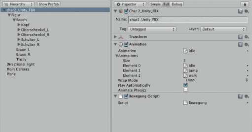
— Figure 4.107: Settings for the animation behavior.
— Figure 4.108: A script for controlling the character.
The basic structure of the script is done, and now we could add some commands for moving the character during its jump or while walking, or add collision detection. This would take us too far from the subject of this chapter, though. The goal of this detour was to show you additional possibilities for character animation and how the new MotioN CliPS of CINEMA 4D can be utilized in that way. Have fun animating!
