
Chapter 1: Making the Most of IPv4
In This Chapter
![]() Getting a grip on the IP address structure
Getting a grip on the IP address structure
![]() Understanding IP network classes
Understanding IP network classes
![]() Working with special IP addresses
Working with special IP addresses
![]() Understanding subnetting
Understanding subnetting
![]() Updating your knowledge with Classless InterDomain Routing
Updating your knowledge with Classless InterDomain Routing
Internet Protocol (IP) version 4 (IPv4) is the current standard “IP” protocol used with TCP/IP — Transmission Control Protocol/Internet Protocol — which is the protocol for Internet addressing. In this chapter, you see how IP addresses are structured and broken down into categories and then further broken down for management. None of this information should strike you as too difficult, especially if you have already made your way through Book I.
![]() In this chapter, when I refer to IP, I mean IPv4. I discuss IP version 6 (IPv6) (the new standard that is just starting to be rolled out as of this writing), in detail in Chapter 4 of this minibook.
In this chapter, when I refer to IP, I mean IPv4. I discuss IP version 6 (IPv6) (the new standard that is just starting to be rolled out as of this writing), in detail in Chapter 4 of this minibook.
By the end of this chapter, you
• Have a basic idea of an IP address and its structure.
• Know the purpose of the subnet mask.
![]() The preceding two items, in particular, play a big role in TCP/IP, as well as most actions that you will perform with your Cisco devices, especially your routers and firewalls.
The preceding two items, in particular, play a big role in TCP/IP, as well as most actions that you will perform with your Cisco devices, especially your routers and firewalls.
• Be able to identify the class to which any address belongs and how the classes relate.
• Know how to reconfigure networks into smaller or larger pieces by manipulating the subnet mask.
The last half of this chapter has you diving into subnetting pretty heavily, but before you start wading in that direction, first check out the nearby sidebar for a brief history of the Internet as a leisurely distraction for your inner geek.
Meeting TCP/IP, Belle of the Networking Ball
TCP/IP, the protocol suite used to connect computers on the Internet, comprises many protocols that function at different levels of the network model. There are network protocols, transport protocols, and application protocols. In fact, the number of protocols is innumerable:
• SMTP: Simple Mail Transport Protocol
• POP3: Post Office Protocol version 3
• HTTP: HyperText Transfer Protocol
• FTP: File Transfer Protocol
• IMAP: Internet Message Access Protocol
![]() TCP/IP is actually a suite of protocols that covers all aspects of the communication process.
TCP/IP is actually a suite of protocols that covers all aspects of the communication process.
Comparing TCP/IP with the OSI Network Model
Like the Open System Interconnection (OSI) model, TCP/IP has its own model. The OSI model and the TCP/IP models were both created independently. The TCP/IP network model represents reality in the world, whereas the OSI mode represents an ideal. With that said, the TCP/IP network model matches the standard layered network model as it should.
Examining Figure 1-1 shows the relationship between the OSI model and the TCP/IP model. This chapter focuses on the IP layer of the model, and Chapter 2 of this minibook examines the TCP and User Diagram Protocol (UDP) layer.
Figure 1-1: Comparing the TCP/IP model with the OSI network model.
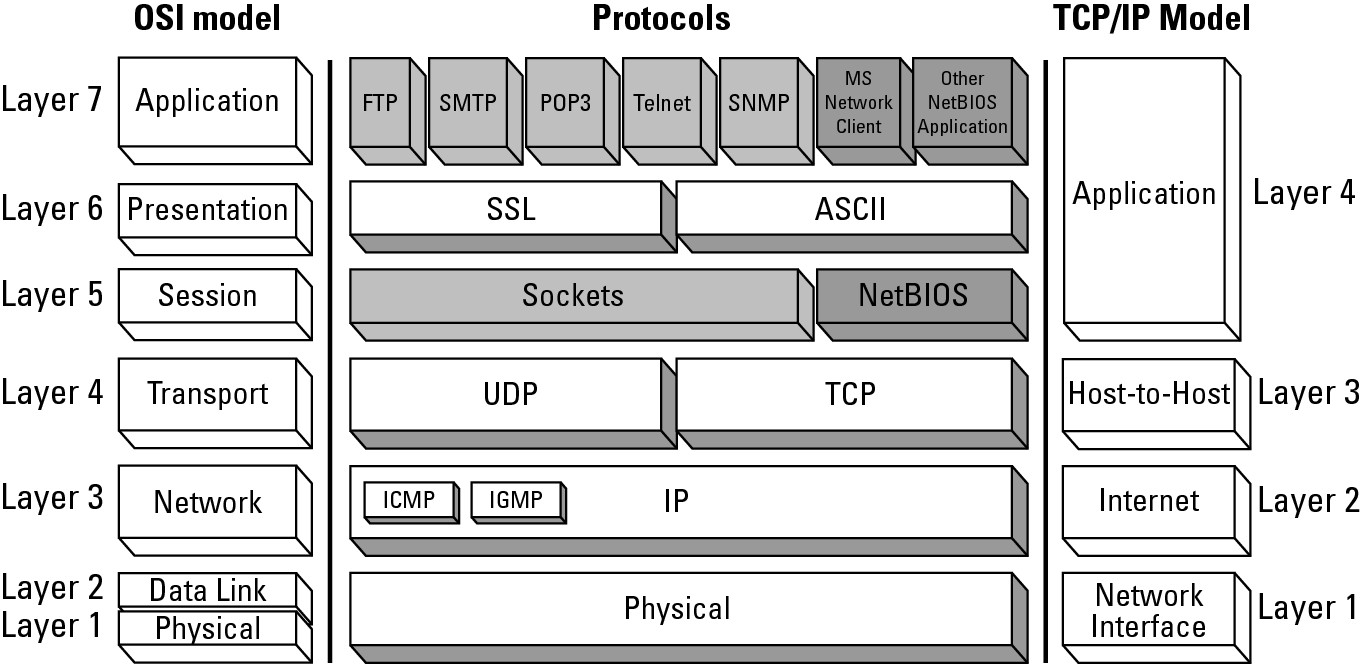
The TCP/IP network model has four basic layers:
• Network interface (layer 1): Deals with all physical components of network connectivity between the network and the IP protocol
• Internet (layer 2): Contains all functionality that manages the movement of data between two network devices over a routed network
• Host-to-host (layer 3): Manages the flow of traffic between two hosts or devices, ensuring that data arrives at the application on the host for which it is targeted
• Application (layer 4): Acts as final endpoints at either end of a communication session between two network hosts
Comprehending the Structure of an IP Address
At its heart, an IP address is just a 32-bit (or 32-digit binary) number. Although you typically see IP addresses written in dotted decimal notation (192.0.2.205), the IP address can also be written in binary (see Figure 1-2). To understand concepts, such as subnetting, in this chapter, it is easier to understand when working with the addresses in binary, so for much of what you look at in this chapter, I go back to binary several times; things just seem to make more sense that way. You are likely accustomed to seeing IP addresses converted from binary to decimal (see Book I, Chapter 3).
The 32 bits in an IP address are separated into four groups, with each group having eight bits. Eight bits is a byte, which can also be referred to as an octet. When working with IP addresses, the term octet is pretty well the exclusive way to refer to each section of the address. From left to right, that would be octet one, two, three, and four.
Figure 1-2: A binary and decimal represent-ation of an IP address.
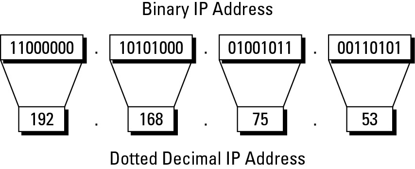
As you progress through the next section, you can see exactly how the address structure is used.
Knowing Your Network Classes
IP networking has five main network classes — A through E — and knowing network classes becomes an issue when you deal with routing.
![]() All actual network IDs and addresses are managed and distributed by the Internet Assigned Number Authority (IANA), which manages the entire pool of addresses. Addresses used to be permanently assigned to organizations, and any organizations (government, universities, or corporations) could purchase an address block (typically, a class network). During the 1990’s, IANA and IAB realized that IP addresses were being consumed faster than expected and in light of the shortage of IP addresses, this practice has slowed to almost a stop. Currently, if you need public IP addresses, your Internet service provider (ISP) usually lease you an appropriately sized block while you get your Internet services from that ISP. The day of companies purchasing IP addresses are in the past.
All actual network IDs and addresses are managed and distributed by the Internet Assigned Number Authority (IANA), which manages the entire pool of addresses. Addresses used to be permanently assigned to organizations, and any organizations (government, universities, or corporations) could purchase an address block (typically, a class network). During the 1990’s, IANA and IAB realized that IP addresses were being consumed faster than expected and in light of the shortage of IP addresses, this practice has slowed to almost a stop. Currently, if you need public IP addresses, your Internet service provider (ISP) usually lease you an appropriately sized block while you get your Internet services from that ISP. The day of companies purchasing IP addresses are in the past.
This section looks at the address classes in descending size order, from Class A to Class E.
Class A
Class A addresses are IP addresses that are assigned to network devices, such as computers, and include all addresses in which the first bit of the first octet is set to 0 (zero). This includes all values from 00000001 to 01111111, or 1 to 127. For Class A networks, the first octet represents a network ID that is defined in the address by a subnet mask, but I cover that in the section “Breaking Up Networks with Subnetting” later in this chapter.
The network ID is not allowed to have all its bits set to 0 or all bits set to 1. You will also find out shortly (in the “Examining special IP addresses” section) why the 127 network ID is excluded from this address class.
Thus, 126 possible Class A networks are available to organizations around the world. With only 126 Class A networks, owning one puts you in an exclusive club. (As I mention earlier, you can no longer acquire a network block of addresses, and when possible, IANA gets them back from the registered owners. Getting addresses back allows IANA to redistribute addresses in a more efficient and temporary manner.)
Class B
Class B addresses are IP addresses that are assigned to network devices, such as computers, and include all addresses in which the first two bits of the first octet are 10. This includes all values from 10000000 to 10111111, or 128 to 191. The definition of the Class B network is represented with a subnet mask (which I discuss in the section “Breaking Up Networks with Subnetting” later in this chapter), but the Class B network ID is made up of the values in the first two octets. Unlike Class A networks, all network IDs in this range are available for use.
Class C
Class C addresses are IP addresses that are assigned to network devices, such as computers, and include all addresses in which the first three bits of the first octet are set to 110. This includes all values from 11000000 to 11011111, or 192 to 223. The default subnet mask for Class C networks defines the first three octets as the network ID for these networks. Like with Class B networks, all the network IDs are available for use on networks. This is the last of the network classes that will be used for network devices on a TCP/IP network.
Class D
Class D network addresses are not assigned to devices on a network. These addresses are used for special-purpose, multicast applications (such as video- and audio-streaming applications). I discuss multicast addresses in Book IV, Chapter 9 when I discuss multicast routing; many processes are used on network devices that communicate with other devices via multicast addresses.
These addresses all need to be registered with IANA to be used globally. Addresses in this class have the first bits of the first octet set to 1110, yielding addresses in the first octet ranging from 11100000 to 11101111, or 224 to 239. These addresses are not defined by a normal subnet mask; instead, each address is used for a specific purpose. And because each address is individually used, it uses a 255.255.255.255 mask, which I discuss later in this chapter in the section “Breaking Up Networks with Subnetting.”
Class E
If Class D is special, Class E addresses are even more special. There is no defined use for this address class. Officially, it is listed as reserved for usage and testing by IANA and the Internet Research Task Force (IRTF). In fact, as of RFC3330 in 2002, Class E was updated to “reserved for future use.”
Network destination addresses
In Book I, Chapter 2, you look briefly at the data link layer address classifications of unicast, multicast, and broadcast. These three classifications of addresses also apply to the network layer, and specifically to the IP protocol. At the network level, here is how these three address classes work:
![]() Unicast: Unique IP address from the Class A, B, or C address ranges. A unicast IP address is always associated with a MAC address for the network interface on which it operates. So if your network device has a network interface for which you have configured an IP address, the IP address uniquely identifies your computer at the network layer. At the same time, at the data link layer, the MAC address associated with the configured network interface uniquely identifies the network device at the data link layer. So there is a one-to-one relationship between unicast addresses at the data link and network layers, and data being sent to a unicast address is processed only by one device on the network.
Unicast: Unique IP address from the Class A, B, or C address ranges. A unicast IP address is always associated with a MAC address for the network interface on which it operates. So if your network device has a network interface for which you have configured an IP address, the IP address uniquely identifies your computer at the network layer. At the same time, at the data link layer, the MAC address associated with the configured network interface uniquely identifies the network device at the data link layer. So there is a one-to-one relationship between unicast addresses at the data link and network layers, and data being sent to a unicast address is processed only by one device on the network.
![]() Multicast: Of the three IP address categories, this is the one that is tough to understand. A multicast address, which is a Class D address, is associated with a group of network devices. When you send data to the multicast address, it is received by all the devices that are a member of the multicast group. Unlike the unicast address, multiple network devices can be configured to receive data sent to this address. This is useful when sending the same data to multiple devices, such as streaming music or installing a disk image on 50 computers. Instead of sending 50 copies of the data to 50 unicast addresses, multicast allows you to send one copy of the data, and all 50 computers receive it. Unlike broadcast, covered in just a bit, this data is processed only by the devices that are in the group, and not all devices on the network.
Multicast: Of the three IP address categories, this is the one that is tough to understand. A multicast address, which is a Class D address, is associated with a group of network devices. When you send data to the multicast address, it is received by all the devices that are a member of the multicast group. Unlike the unicast address, multiple network devices can be configured to receive data sent to this address. This is useful when sending the same data to multiple devices, such as streaming music or installing a disk image on 50 computers. Instead of sending 50 copies of the data to 50 unicast addresses, multicast allows you to send one copy of the data, and all 50 computers receive it. Unlike broadcast, covered in just a bit, this data is processed only by the devices that are in the group, and not all devices on the network.
At the data link layer, IANA has registered an Organizationally Unique Identifier (OUI) like how a network card manufacturer would register (read Book I, Chapter 4 to find out more about manufacturer IDs). In this case, instead of using this MAC address block to be assigned to network cards, IANA uses this MAC address range (01:00:5e:00:00:00 to 01:00:5e:7f:ff:ff) to associate IP multicast addresses at the network layer to MAC addresses at the data link layer. This MAC address range is a little smaller than the IP address range, so there is small potential overlap, but this does not present an issue for the multicast traffic.
The registration of the IANA MAC range allows an IP multicast address to map to a MAC address at the data link layer, but it does require that your network switch supports the IANA multicast range; if it does not, the switch treats IP multicast traffic as broadcast traffic (see the next point) at the data link layer.
![]() Broadcast: Special group IP addresses technically include all IP network devices in the world but actually map directly to the MAC broadcast address on your current data link. If you look at the broadcast IP address in binary, all the bits are set to 1, which is 255.255.255.255 in the standard dotted decimal notation. The broadcast MAC address that this IP broadcast maps to also has all its binary bits set to 1, so the address is FF:FF:FF:FF:FF:FF.
Broadcast: Special group IP addresses technically include all IP network devices in the world but actually map directly to the MAC broadcast address on your current data link. If you look at the broadcast IP address in binary, all the bits are set to 1, which is 255.255.255.255 in the standard dotted decimal notation. The broadcast MAC address that this IP broadcast maps to also has all its binary bits set to 1, so the address is FF:FF:FF:FF:FF:FF.
Any network frames that are sent to the broadcast address are read or processed by every device on that network segment.
Class E comprises absolutely all valid addresses with 240 or higher in the first octet. The first bits of the first octet is 1111, which yields addresses from 11110000 to 11111110 — or technically, 11111111 — which, in decimals, are 240 to 254 — or 255. Because this address class is not being used for address allocation, you cannot know what the network ID, which defines the valid addresses in a range, is. So the inclusion of 255 at the end of the range is moot because this address range is not available for you to use. All you need to know is that by definition Class E includes all valid addresses higher than Class D.
Public, private, and automatic IP addresses
Space is running out for people to assign addresses to their devices. Companies or organizations acquire addresses to assign to their network devices, such as smartphones, PCs, servers, routers, and tablets, just to name a few. As these devices proliferate, the number of available addresses can drop dramatically.
As a solution to that issue, in 1996, IANA and IETF came up with private addressing, which allows organizations to use a large address space internally on their network while using only a few public addresses, rather than using only public addresses. For this to happen, IANA requires that some public addresses be removed from the global pool. These addresses were either pulled back or voluntarily surrendered by address holders. (This address space change was documented in RFC1918.) The addresses available for usage include 1 Class A network, 16 Class B networks, and 255 Class C networks, which I summarize in Table 1-1. These addresses are now widely used by all organizations on the Internet. These addresses and others can be found in RFC5735, Special Use IPv4 Addresses.
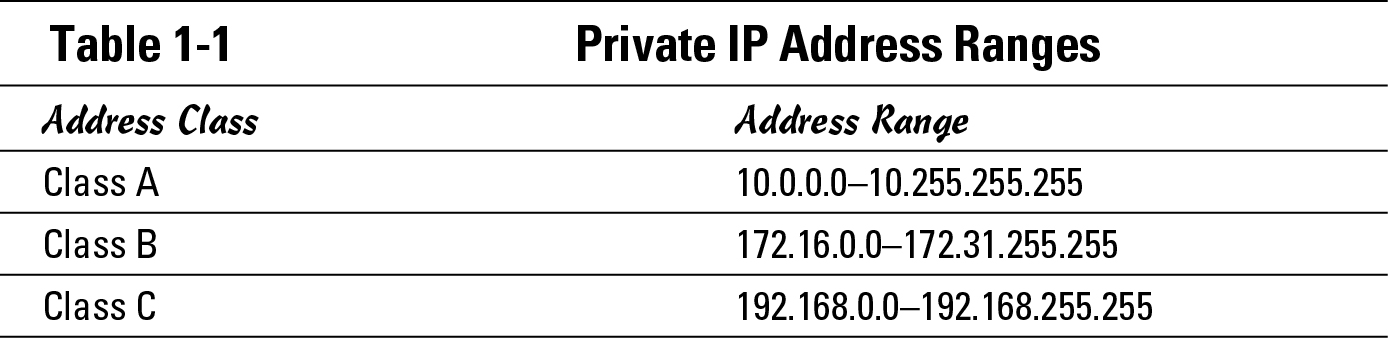
![]() Private addresses are not allowed to be routed out to the Internet, so devices using private addresses cannot communicate directly with devices on the Internet. To make private IP addressing functional and resolve this issue, at least one public address is required, which will be used with Network Address Translation (NAT) or Port Address Translation (PAT). (I cover NAT and PAT in Book VI, Chapter 3.) So a company using private addresses internally still requires at least one address to connect their private network with the Internet.
Private addresses are not allowed to be routed out to the Internet, so devices using private addresses cannot communicate directly with devices on the Internet. To make private IP addressing functional and resolve this issue, at least one public address is required, which will be used with Network Address Translation (NAT) or Port Address Translation (PAT). (I cover NAT and PAT in Book VI, Chapter 3.) So a company using private addresses internally still requires at least one address to connect their private network with the Internet.
In addition to the private addresses, Microsoft took a leading role in defining RFC3927 Dynamic Configuration of IPv4 Link-Local Addresses. This defines the process that computers should take in situations where there are no other methods of applying dynamic IP address assignments. This process was created to deal with situations where you do not want to — or cannot — manually assign static IP addresses and there is no Dynamic Host Configuration Protocol (DHCP) server on your network to automatically assign addresses.
The solution was to use another IP address range — in this case, a Class B network of 169.254.0.0 — to let IP hosts choose their own address. In this range, there are approximately 65,000 addresses from which the IP host can choose, so the basic process for the host is as follows:
1. Randomly choose an address from the range 169.254.0.1–169.254.255.254.
2. Send an Address Resolution Protocol (ARP) request for the MAC address that has the chosen address to eliminate the chance of duplicate IP address conflicts.
If no response is received to the ARP request, no other computer is using that IP address so the host can start using the IP address chosen in Step 1.
The preceding steps outline the Automatic Private IP Addressing (APIPA) process. When two or more computers on the same data link support the use of, and are configured to use, APIPA, these hosts can communicate with each other. This process was created to simplify ad hoc (or temporary) networks in which TCP/IP is the primary networking protocol because APIPA eliminates the need to manually assign addresses to hosts.
Examining special IP addresses
When networking with TCP/IP, you can work with some special IP addresses. When working with each network segment, here are two special addresses that you deal with:
• The IP address of the network ID
• The IP address of the network broadcast address
Although both the network ID and network broadcast address look like IP addresses, because of their special purposes, they are not valid addresses that can be assigned to IP hosts to devices on your network. To identify these two special addresses, start by taking an IP address and writing it in binary rather than dotted decimal notation. So for the address 192.0.2.242, binary looks like this:
11000000.00000000.00000001.11110010
If you refer to the “Class C” section earlier in this chapter, addresses starting with 192 in the first octet are Class C and the first three octets are used for the network ID. If you leave the bits in the network ID portion of the address alone but set the remaining bits (the host portion of the address) to all binary 0s, you are looking at the network ID of the network. Here is what this looks like in binary.
11000000.00000000.00000001.00000000
In dotted decimal notation, that address looks like 192.0.2.0, which is the network ID for the network that contains 192.0.2.242.
When the host portion of the address is set to all binary 1s, it looks like this:
11000000.00000000.00000001.11111111
In dotted decimal notation, this address looks like 192.0.2.255; that is the network broadcast address, or the broadcast address for the 192.0.2.0 network. The broadcast address here is slightly different from the broadcast address I define earlier in the sidebar “Network destination addresses;” rather than going to all IP hosts on the current network segment, it is processed only by those whose IP network ID is 192.0.2.0, which is a small difference because I will typically have only one network ID in use on a network segment.
In addition to these two special addresses per network segment, three other addresses are of interest:
• 127.0.0.1: In electronics, a loopback is used to take data that you send from a device and pass it back to the receiving side of the device. A loopback tests that both the sending and receiving sides of the device are functioning. The loopback address in TCP/IP serves the same function; it verifies that IP on the local host can communicate with IP on the local host. This ensures that your TCP/IP protocol is properly installed and working on your network device. In most operating systems, this address is configured on a virtual network interface — the loopback adapter (think loopback network card). In actuality, the loopback address space is the entire Class A network of 127.0.0.0, so you can technically use any of the addresses in this range for loopback testing.
• 255.255.255.255: This is the general broadcast or all-networks broadcast address, which I discuss earlier in the sidebar “Network destination addresses”. Unlike the network broadcast address in which the host portion of an IP address is set to binary 1s and the network portion of the address remains the same, this address sets the network portion to binary 1s as well. Having both the host and network ID portions of the address set to binary 1s means that the destination of the 255.255.255.255 address is all hosts on all networks. By definition, all hosts on all networks means all networks in the world, but a router will not forward a broadcast from one network to another network; so in actuality this really means all hosts using any network ID on this network segment. Although it is normal to have only one network ID in operation on each network segment of your network, the use of the general broadcast address (instead of the network broadcast address), ensures that devices using other network IDs on the network segment will receive the data being set to the broadcast address.
• 0.0.0.0: This is the opposite of a general broadcast, which goes out to all devices or “them;” this address represents “me” or “this.” This concept is very abstract, in that this address is not an address you can test connectivity to. The time when you will typically see this address is when setting up a default route, which matches all the me’s that exist in the world, using the address of 0.0.0.0 and the mask of 0.0.0.0. Just remember that 0.0.0.0 is a special address and move on with your life, and this book.
Breaking Up Networks with Subnetting
Subnet is short for subnetwork, or a portion of the complete network. In theory, all IP addresses belong to one large network that has been initially broken up into the class-based segments (flip back to the section “Knowing Your Network Classes”) with the size of the networks in each class identified by a default subnet mask. The subnet mask defines what portion of the IP address is used as a network ID and which portion is used as a host ID. By adjusting the default subnet mask, you can take the class-based network and break it into smaller network pieces (or subnetworks) for use across your network devices.
The main reason you want to perform this breakup of your network addresses occurs when you have a router on your network. Your router requires a network ID (or a distinct range of addresses) to be associated with each network interface on the router. If you have only one block of IP addresses in the form of a network ID and subnet mask, you need to split the block into at least two pieces for use with your router. Subnetting then is the action of splitting your network’s IP address block into pieces.
![]() One concept that may help you here is the concept of ANDing, which I cover in Chapter 3 of this minibook. ANDing is a mathematical or logical process used to work with binary numbers to determine the scope of a network, indentifying what computers are on a network verses those that are on another network. If you end up being a little confused here, you can skip ahead and come back here.
One concept that may help you here is the concept of ANDing, which I cover in Chapter 3 of this minibook. ANDing is a mathematical or logical process used to work with binary numbers to determine the scope of a network, indentifying what computers are on a network verses those that are on another network. If you end up being a little confused here, you can skip ahead and come back here.
Subnetting 101
If you have worked with IP for very long, you know that the three big things that you configure for a TCP/IP host are
• IP address: The specific unique IP address used to identify the host on the network
• Subnet mask: Used to define how many hosts can exist on a network
• Default gateway: The IP address assigned to your router, which is the device you use to send data to hosts on other networks
Here is the output of ipconfig.exe on a Microsoft Windows computer showing this information:
C:>ipconfig
Windows IP Configuration
Ethernet adapter Local Area Connection:
Connection-specific DNS Suffix . : edtetz.net
IP Address. . . . . . . . . . . . : 10.0.1.12
Subnet Mask . . . . . . . . . . . : 255.255.255.0
Default Gateway . . . . . . . . . : 10.0.1.254
![]() If you have been working with IP on computers for a while, you might want to say that a Domain Name Server (DNS) is pretty critical, but that relates to resolving names like
If you have been working with IP on computers for a while, you might want to say that a Domain Name Server (DNS) is pretty critical, but that relates to resolving names like www.edtetz.net to an IP address, not allowing two IP addresses on different networks to communicate.
One of the three important pieces of information is the subnet mask. Each classed network has a default subnet mask. Table 1-2 summarizes some of this information based upon these two rules:
• All bits in the network portion of the address are not allowed to be set to 0s or 1s.
• All bits in the host portion of the address are not allowed to be set to 0s or 1s.
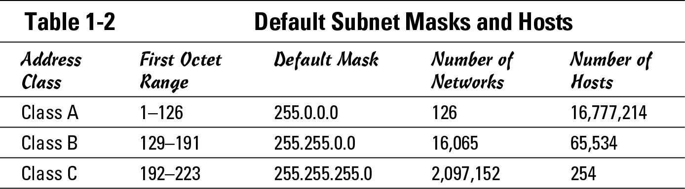
Mulling the number of hosts
Here is where the fourth column of Table 1-2 came from. When looking at the subnet mask, there are two binary numbers at work: 1s and 0s. Here is the Class A mask written in binary:
11111111.00000000.00000000.00000000
In this mask, the 1s represent the part of the mask that identifies the network ID, and the 0s represent the part of the address used as a host ID. So, given an address like 10.75.24.14, the network ID is 10, and the host ID is 75.24.14, uniquely identifying the host on the specific network. Because only the first octet is used as part of the network ID, the only possible network IDs are 1 to 126.
When dealing with Class B networks, where the default subnet mask is 255.255.0.0 and with all the bits in the first two octets being 1s, the network ID is made up of the first two octets with the host ID being in the last two octets. Going one step further, the Class C networks have a default subnet mask of 255.255.255.0 in which the network ID is made up of the first three octets, and the host ID is made up of the last octet.
Earlier in this chapter, I have listed private addresses that I can use internally on my network, such as a single Class A (10.0.0.0), 16 Class B networks (starting at 172.16.0.0), or 256 Class C networks (all 192.168.0.0 networks); Table 1-2 shows the number of hosts that can exist on any network segment. Although 254 hosts represent a reasonable number of devices on a network segment, such as on the Class C network segments, because of network traffic and congestion caused by devices, it is unreasonable to think that you will ever have a network segment that contains 65,534 hosts or 16,777,214 hosts on the Class B or Class A segments. Because you will not have that many hosts on any segment, you can break those large network address block into more — smaller — network address blocks that you will use to assign addresses to a number of smaller network segments.
![]() When you get into the minibook on routing (Book IV), you see that some routing protocols require that the same subnet mask be used on every segment on your network. This next section focuses on that; whereas in the upcoming section “Explaining Classless InterDomain Routing (CIDR),” you read about varying the size of your subnets.
When you get into the minibook on routing (Book IV), you see that some routing protocols require that the same subnet mask be used on every segment on your network. This next section focuses on that; whereas in the upcoming section “Explaining Classless InterDomain Routing (CIDR),” you read about varying the size of your subnets.
Modifying the subnet mask
To break your network into smaller segments, simply modify the subnet mask. It is really as easy as that. You can subnet any of the network classes, even the smaller Class C networks.
So how is this done? Simply, when looking at the subnet mask in binary, take host bits (the 0s) and turn them into subnet bits (the 1s).This action reduces the number of hosts you can put on a network segment, but allows you to have more than one network segment.
By converting bits in the subnet mask, you have created a new section — the subnet section — which is between the network section of the mask and the host section of the mask. The three types of bits in the new subnet mask are network bits, subnet bits, and host bits. This also expands the subnet mask rules that were introduced in the “Subnetting 101” section. The expanded rules are
• All bits in the network portion of the address are not allowed to be set to zero or ones.
• All bits in the host portion of the address are not allowed to be set to zero or ones.
• All bits in the subnet portion of the address are not allowed to be set to all zero or ones. See the upcoming section, “Class C subnetting” for more about the current status of this last rule.
You can see the similarity to the previous rules for addresses, with the addition of the rule around the subnet portion of the address. If I take only one bit from the host and convert it to a subnet bit, it has only two possible combinations — 1 or 0, which is all 1s or all 0s — which is not allowed based on the preceding third rule — so I need to take at least two bits when starting to subnet. I begin by showing you how this would look with the Class A network of 10.0.0.0.
When you start, the default subnet mask for a Class A network looks like this:
11111111.00000000.00000000.00000000
Going forward, take a minimum of two bits from the host range and use them as the subnet. These two bits give you the possible networks, as defined in Table 1-3.
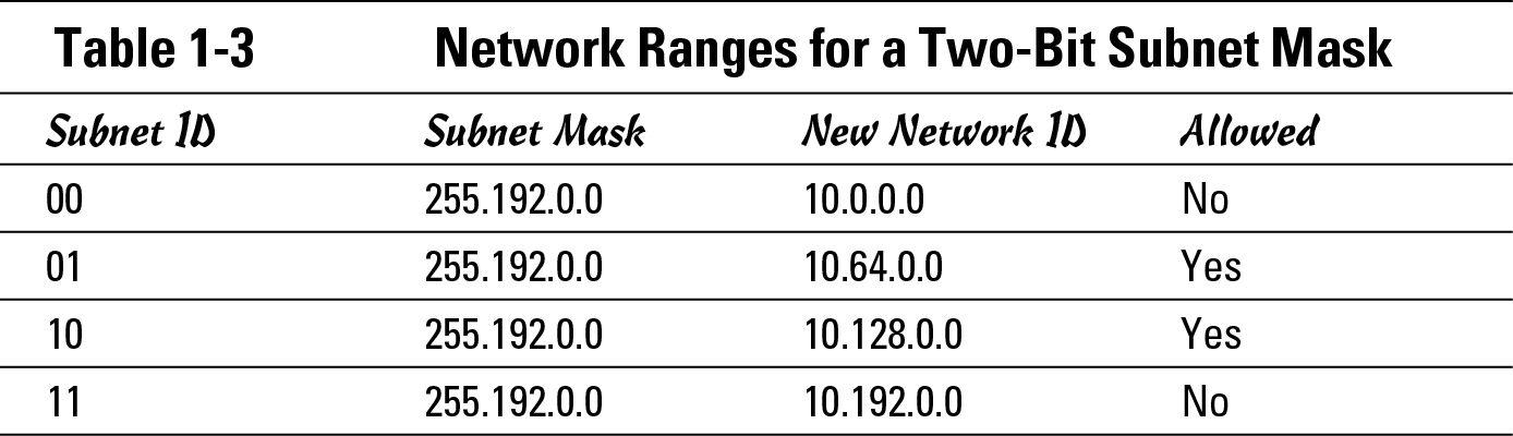
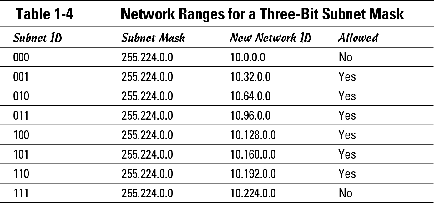
Two subnets — ID 00 and 11 — are not allowed because the subnet ID is all 1s or all 0s. By subnetting this network, you have two network blocks of addresses that you can assign to your network segments. If two network address blocks were not enough to assign unique blocks to each of your network segments — because you have five network segments — you could take another bit from the host range and use that for the subnet range, which I show in Table 1-4.
You might ask how far you can go with this. Keep reading.
Class A subnetting
On a Class A network, you can indeed go quite far because you can continue down to the two bits of the host address space. I have shown the 32-bit address space here, using N for the network ID, S for the subnet ID, and H for the host ID. The two choices here show the lowest number of bits to the largest number of subnet bits:
NNNNNNNN.SSHHHHHH.HHHHHHHH.HHHHHHHH
and
NNNNNNNN.SSSSSSSS.SSSSSSSS.SSSSSSHH
The first example shows 2 subnet bits and 22 host bits, so this would work out to 2^2–2 (or 2) subnets and 2^22–2 hosts per subnet (or 4,194,302), which represents the fewest number of subnets. You could then increase the number of subnets and reduce the number of hosts all the way down to the second example, which has 22 bits for the subnets and only 2 bits for the hosts, giving you 4,194,302 networks of two hosts. This is almost absurd because one of those two hosts would be a router unless you were using these subnets to address the link between two routers.
Class B subnetting
You are not limited to subnetting Class A networks; if you were to look at a Class B network, you would get a range running from these two extremes on the 172.16.0.0 network:
NNNNNNNN.NNNNNNNN.SSHHHHHH.HHHHHHHH
and
NNNNNNNN.NNNNNNNN.SSSSSSSS.SSSSSSHH
In this case, you would still start with two possible subnets, using 2^2–2 (or 2) subnets, but your host bits would be 2^14–2 hosts (or 16,382). Then you would go all the way to 14 bits for the subnet and 2 bits for the host, giving you 16,382 networks of two hosts each. Because you started with a much smaller number of bits, your total number of networks will be far less.
Class C subnetting
Finally, looking at a Class C network, your numbers would look like the following:
NNNNNNNN.NNNNNNNN.NNNNNNNN.SSHHHHHH
and
NNNNNNNN.NNNNNNNN.NNNNNNNN.SSSSSSHH
This scenario would provide you with anything from 2^2–2 (or 2) networks of 2^6 or 62 hosts, down to a low number of 62 networks of 2 hosts.
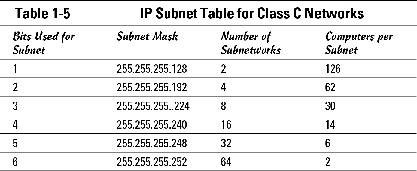
To quickly summarize, which I do with a Class C network to minimize complexity, you can break down a classed network into smaller pieces, which allows you to use these address blocks to assign addresses to each of your physical network segments. This process of breaking down the network into smaller pieces takes host bits — working from left to right — and using them as subnet bits. Table 1-5 shows you all the possible addresses when subnetting the Class C network of 192.168.1.0.
![]() Similar tables are freely available on the Internet for any network class you choose to subnet, or subnet calculators can give you the figures on the fly. A downloadable calculator is available from
Similar tables are freely available on the Internet for any network class you choose to subnet, or subnet calculators can give you the figures on the fly. A downloadable calculator is available from www.boson.com/freeutilities.html, and an online calculator is available at www.subnet-calculator.com.
![]() As I mention earlier in the chapter, although you used to not be allowed to use the all 0s subnet or the all 1s subnet, this is no longer the case. Older routing protocols (such as RIP version 1) had an issue distinguishing a subnet ID of 192.168.1.0/24 from 192.168.1.0/28. Since the advent of Cisco IOS 12.0, subnet zero (and the all ones subnet) has been allowed for usable subnets; and prior to that, you could add the directive in Global Configuration mode of
As I mention earlier in the chapter, although you used to not be allowed to use the all 0s subnet or the all 1s subnet, this is no longer the case. Older routing protocols (such as RIP version 1) had an issue distinguishing a subnet ID of 192.168.1.0/24 from 192.168.1.0/28. Since the advent of Cisco IOS 12.0, subnet zero (and the all ones subnet) has been allowed for usable subnets; and prior to that, you could add the directive in Global Configuration mode of ip subnet-zero to enable you to use all of the 1s and all 0s subnet.
By selecting one of these subnets levels, I show you the exact addresses available on each of the network segments. This data is shown in Table 1-6 for the 192.168.1.0 network, using 3 bits in the subnet mask or a mask of 255.255.255.224. Based on the previous table, this gives you eight networks of 30 devices if you allow for the all 0s and all 1s subnets. Although I calculated this by hand, you can easily find tables similar to this on the Internet.
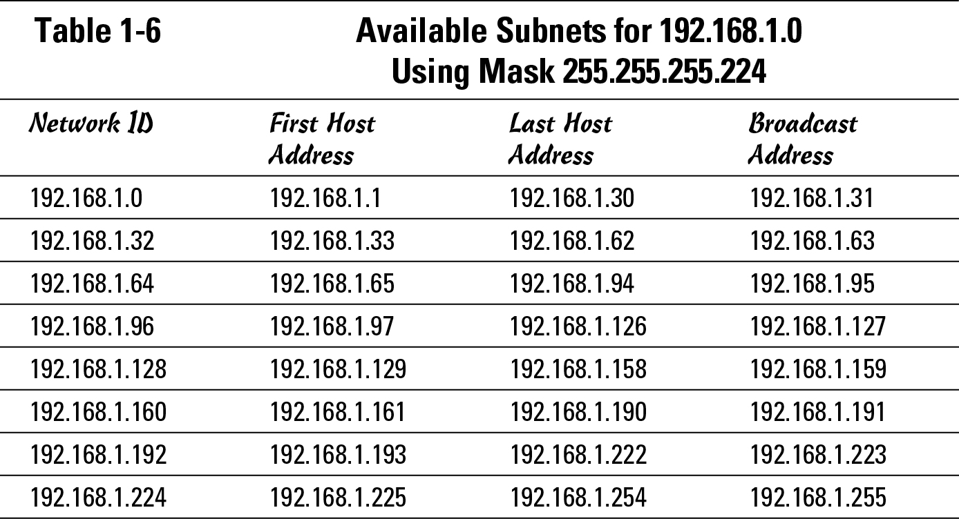
You can see from this table that for each subnetwork, there is a network ID address and a broadcast address. You read in the earlier section “Examining special IP addresses” that these two addresses are not allowed to be used for host addresses because they each have a special purpose; the network ID identifies the network, and the broadcast address sends IP packets to all hosts on the network.
Because current networking says that all your subnets are available, rather than excluding the all-0s and all-1s subnets, that leads into the next topic.
Explaining Classless InterDomain Routing (CIDR)
The inclusion of subnet zero changes the management of your subnet divisions by including two additional subnets, regardless of how many bits you choose to use. This also allows splitting of a network ID into as little as two pieces.
The next big change that happened with subnet management is the removal of network classes. In 1995, a system was proposed to eliminate class-based allocation of IP addresses; this process was updated as a best practice in 2006. With the elimination of classes, which is a paradigm shift for most people, you really start working with addresses as simply blocks of addresses. This means that IP address space, which is used to assign addresses to hosts (Class A, B, and C), is treated as one block of addresses, from 1.0.0.0 to 223.255.255.255, which can be broken along any boundaries defined by a valid subnet mask. Assignment of addresses to organizations is still managed by IANA, with existing assignments remaining in place; but they now have more flexibility in how new addresses are assigned because assignments do not need to follow previous class-based boundaries.
![]() In the minibook on routing (Book IV), you can see that you are limited in your choice of routing protocols if you want to use classless routing. In this section, I focus on a few key elements of CIDR, including
In the minibook on routing (Book IV), you can see that you are limited in your choice of routing protocols if you want to use classless routing. In this section, I focus on a few key elements of CIDR, including
• CIDR notation
• Variable Length Subnet Masks (VLSM)
• Route summarization
• Supernetting
The key to CIDR is that rather than using network classes, defining how big each network segment should be, you ignore the class boundaries and treat the entire address space from 1.0.0.0–223.255.255.255 as one continuous address space that can have blocks of addresses separated by specifying a correct starting address and a subnet mask.
This still allows you to follow boundaries that existed prior to going classless, but then gives you flexibility to expand ranges beyond ordinary class boundaries, or work with sections of the network smaller than the ordinary class boundaries. When working with segments smaller than class boundaries, you do not need to worry about eliminating the first and last ranges when subnetting because you did not start with a class-based network. Thus, there is not really a first and last block of addresses in that numeric range but rather just a block of numbers, defined by a starting address and a subnet mask.
CIDR notation
When you are writing a long list of subnets or network addresses, you can easily get a cramp in your hand writing all the subnet masks, for example, if you have to write this list of network IDs:
network ID: 192.168.0.0, Subnet Mask: 255.255.255.0
network ID: 192.168.3.0, Subnet Mask: 255.255.255.0
network ID: 192.168.6.0, Subnet Mask: 255.255.255.0
network ID: 192.168.45.0, Subnet Mask: 255.255.255.0
network ID: 192.168.93.0, Subnet Mask: 255.255.255.0
network ID: 192.168.115.0, Subnet Mask: 255.255.255.0
CIDR notation makes this a little easier for you by allowing you to specify a subnet mask as a number of bits that exist in the subnet mask. The CIDR list of network IDs would look like this:
network ID: 192.168.0.0/24
network ID: 192.168.3.0/24
network ID: 192.168.6.0/24
network ID: 192.168.45.0/24
network ID: 192.168.93.0/24
Table 1-7 lists all possible masks you will encounter during your use of IP and the CIDR notation for them.
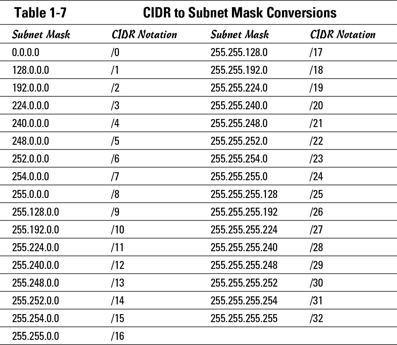
![]() This means that if I want to relay information to you about a Class A network, I can refer to my network as 10.0.0.0/8 rather than 10.0.0.0 255.0.0.0, a Class B network as 172.16.0.0/16, or a Class C network as 192.168.1.0/24. This reference of the bits used in the subnet mask, rather than writing the entire mask, makes life much easier.
This means that if I want to relay information to you about a Class A network, I can refer to my network as 10.0.0.0/8 rather than 10.0.0.0 255.0.0.0, a Class B network as 172.16.0.0/16, or a Class C network as 192.168.1.0/24. This reference of the bits used in the subnet mask, rather than writing the entire mask, makes life much easier.
Variable Length Subnet Masks (VLSM)
When first working with subnetting, and in order to support certain routing protocols, all network segments on the network must use the same subnet mask. Some early routing protocols made decisions on what they expected remote subnet masks to be based on what their subnet mask was, thereby requiring that all subnets of that network use the same mask. With the inclusion of subnet masks in all routing tables, you allow the routing protocol to support Variable Length Subnet Masks (VLSM) with which, simply put, you do not need to use the same subnet mask on all your network segments and can vary the mask from segment to segment. This concept is covered in RFC1878 Variable Length Subnet Table for IPv4, which effectively says devices should be smart enough to define each subnet individually.
So how does this work? Say that I take an address block, such as 192.168.1.0/24. From this block, I need to provision a network, as shown in Figure 1-3, and determine that I need eight segments used as interconnects between networks on serial links and also I need to support a main office of 60 computers, two regional offices of 25 computers, and 6 other offices with computers each.
Figure 1-3:
VLSM deployment of network addresses.
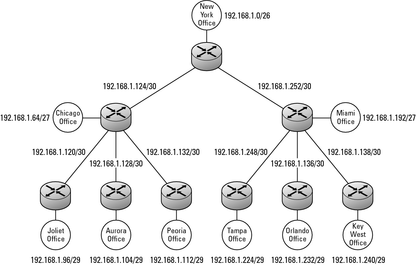
If you review the address blocks that are assigned in this figure, you see that a few gaps are still available. One block of addresses, from 192.168.1.144 to 191.168.1.191, is available. The size of the blocks that can be carved from this range are dependent upon the pieces that have been removed already. The largest single block that can be used out of this range is 192.168.1.160–192.168.1.191 (or 192.168.1.160/27), followed by 192.168.1.144–192.168.1.159 (or 192.168.144/28), and either of these can be deployed as smaller segments.
By switching from fixed-length subnet masks to VSMLs, you can use far more addresses that you can with fixed-length subnet masks. To use a subnet mask on a traditional network, you would have had to subnet 17 blocks of 62 addresses (the largest single segment), which would have used the equivalent of five Class C address blocks, resulting in 192.168.1.0/24, 192.168.2.0/24, 192.168.3.0/24, 192.168.4.0/24 and 192.168.5.0/24, with three of four blocks in the last network block still available. This represents a large waste of addresses in the overall IP address space. So, as you can see, VLSM yields a large savings in the utilization of IP address space.
Supernetting
The concept of supernetting lends itself nicely to CIDR because it also allows you to ignore class boundaries. When you started your office network, you may have chosen to use the private Class C address space to assign host addresses for your network devices. At the beginning of this running example, your central office had fewer than 60 devices, so you allocated a network of 192.168.0.0/26 to that segment. Over time, the number of devices on the network increased. If you did not yet allocate the address space of 192.168.0.64/26 to any other network segment, you can join 192.168.0.0/26 and 192.168.0.64/26 into a single larger network segment by reassigning the subnet masks to all your hosts, giving you a network of 129.168.0.0/25. This is, however, still in the realm of subnetting because you are dealing with networks smaller than the default class-based network blocks.
Playing out this scenario further, the number of devices increases over time, and you need to repeat the process. If the address blocks of 192.168.0.128/26 and 192.168.0.192/26 or 192.168.0.128/25 are still available, you can merge the address spaces again, but reassign the subnet masks of your network devices to 192.168.0.0/24, which is the default class-based mask for a Class C network.
Things are now stable on your network until the number of devices on the central office network approached the 254 limit of the network segment. When that occurs, you have a choice.
Say that you decided to use the Class C private address space for your network segments, but now your devices have increased to a level that goes beyond the size of a Class C segment. You could break down and use a Class B address block, which is easy enough if you are using private addresses; however, if this network used public addresses, this would not happen because you would never convince IANA or your Internet service provider (ISP) to let you have a Class B address block — even if you were going to try to get a second Class C address block address, you would not have a chance.
So back to the private address space. If you have not allocated the private Class C address block of 192.168.1.0 to any other devices on your network, you can continue the process of joining address blocks by changing the mask from 24 bits to 23 bits. Thus, the network block assignment of 192.168.0.0/23 would include all addresses from 192.168.0.1–192.168.1.254, essentially joining those two Class C blocks into a single address block. This is supernetting.
Notice that when you think in classless terms, supernetting is not a big stretch in thought; after all, you just modify the mask to include a larger address block. For people stuck in the class-based world, this is a huge logical jump.
![]() You are limited by the binary network IDs as to which network segments can be joined. For example, 192.168.1.0/24 can be merged with 192.168.0.0/24, but not 192.168.2.0/24. If you convert everything to binary, network address, and masks, you easily see which two network blocks yield the same network ID when supernetting. Look at the three example network IDs along with the 23-bit subnet mask (255.255.254.0), and you see which network IDs have the first 23 bits that match. Because 192.168.0.0 and 192.168.1.0 match for the first 23 bits, they can be combined into the 192.168.0.0/23 network:
You are limited by the binary network IDs as to which network segments can be joined. For example, 192.168.1.0/24 can be merged with 192.168.0.0/24, but not 192.168.2.0/24. If you convert everything to binary, network address, and masks, you easily see which two network blocks yield the same network ID when supernetting. Look at the three example network IDs along with the 23-bit subnet mask (255.255.254.0), and you see which network IDs have the first 23 bits that match. Because 192.168.0.0 and 192.168.1.0 match for the first 23 bits, they can be combined into the 192.168.0.0/23 network:
11000000.10101000.0000000.00000000 (192.168.0.0)
11000000.10101000.0000001.00000000 (192.168.1.0)
11000000.10101000.0000010.00000000 (192.168.2.0)
11111111.11111111.1111110.00000000 (255.255.254.0) route summarization
Continuing from supernetting, route summarization should be very easy to follow. Route summarization can take place on routers to reduce the size of their routing tables. A routing table is a list of routing entries, each of which includes a network ID of a network segment and the address of the next closest router to that network segment. You see how the routing tables work in Book IV, but now is a good time to introduce you to the technical side of route summarization.
A basic router table entry has three basic elements:
• A network ID
• A subnet mask
• The address of the next router to get you to that network
Referring to Figure 1-3, you can assign the lowest address in router-to-router connection at the central office connections to the central office router. This means that the regional office routers (in Chicago and Miami) will be addressed as 192.168.1.134 and 192.168.1.138. And that means that the routing table on the New York office router would look something like this:
network ID Mask Gateway
192.168.1.0 255.255.255.192 192.168.1.1
192.168.1.64 255.255.255.224 192.168.1.134
192.168.1.96 255.255.255.248 192.168.1.134
192.168.1.104 255.255.255.248 192.168.1.134
192.168.1.112 255.255.255.248 192.168.1.134
192.168.1.120 255.255.255.252 192.168.1.134
192.168.1.124 255.255.255.252 192.168.1.134
192.168.1.128 255.255.255.252 192.168.1.134
192.168.1.132 255.255.255.252 192.168.1.133
192.168.1.136 255.255.255.252 192.168.1.137
192.168.1.140 255.255.255.252 192.168.1.138
192.168.1.192 255.255.255.224 192.168.1.138
192.168.1.224 255.255.255.248 192.168.1.138
192.168.1.232 255.255.255.248 192.168.1.138
192.168.1.240 255.255.255.248 192.168.1.138
192.168.1.248 255.255.255.252 192.168.1.138
192.168.1.252 255.255.255.252 192.168.1.138
![]() Each character takes up memory on your router. So, as your network size increases, the amount of storage required for your routing table increases. Route summarization reduces the number of entries in the table, and follows the same basic process of supernetting.
Each character takes up memory on your router. So, as your network size increases, the amount of storage required for your routing table increases. Route summarization reduces the number of entries in the table, and follows the same basic process of supernetting.
If you were to take all the addresses in the previous listing and convert all the network IDs over to binary (as I did in the example at the end of the “Supernetting” section), and then compared all the addresses going to a single destination, you would find that bit patterns in the network IDs would allow you to combine entries by reducing the length of the subnet mask. To take a small section of the table as an example, I work with the entries that use the gateway of 192.168.1.134. Here are all the entries in binary:
11000000.10101000.0000001.00011000 (192.168.1.64)
11000000.10101000.0000001.01100000 (192.168.1.96)
11000000.10101000.0000001.01101000 (192.168.1.104)
11000000.10101000.0000001.01110000 (192.168.1.112)
11000000.10101000.0000001.01111000 (192.168.1.120)
11000000.10101000.0000001.01111100 (192.168.1.124)
11000000.10101000.0000001.10000000 (192.168.1.128)
Reviewing this list, you may have noticed that the first six addresses match the first 25-bits in their addresses. Referring back to Table 1-7, you find out that the 25-bit subnet mask is 255.255.255.192, so the first six entries can be combined into a single entry defined by the network ID of 192.168.1.64 and a mask of 255.255.255.192. If you continued this process of summarization for the entire previous routing table, you could summarize the entire table to the following:
network ID Mask Gateway
192.168.1.0 255.255.255.192 192.168.1.1
192.168.1.64 255.255.255.192 192.168.1.134
192.168.1.128 255.255.255.252 192.168.1.134
192.168.1.132 255.255.255.252 192.168.1.133
192.168.1.136 255.255.255.252 192.168.1.137
192.168.1.140 55.255.255.252 192.168.1.138
192.168.1.192 255.255.255.192 192.168.1.138
By summarizing the routes, you can reduce the routing table size from 17 entries to 7 entries. If in this example, you had chosen to lay out the addresses slightly differently or used addresses from two Class C blocks, rather than limiting yourself to one, additional summarization would have been possible.