
Chapter 1: Making the Wide Area Network (WAN) Wide
In This Chapter
![]() Identifying the differences between WAN types
Identifying the differences between WAN types
![]() Introducing routing protocols
Introducing routing protocols
This minibook on routing logically begins with where you are likely to use routers. Although some people use routers on the interior of a well-connected network to separate a larger number of users or to aid in implementing a set of security features, most people use routers to connect remote offices that are linked through their telephone company’s network infrastructure.
This chapter looks at the key elements of technologies you can use to make the connections between all your routers. In addition to covering the infrastructure elements, I introduce you to different routing protocols you can implement for your wide area network (WAN).
Identifying Features of a WAN
First, I want to explain what makes up a WAN. Sometimes people want to identify a WAN by the size of the network or by the devices that compose the network, but I disagree with both methods of classification. For example, if your network has 5,000, or even 100,000, devices and you are not using WAN technologies to interconnect them, you do not necessarily have a WAN. If you have a large campus network using routers and dynamic routing protocols and the infrastructure that it runs over is all internal to your organization, you do not necessarily have a WAN.
So, in case you have not already guessed, a WAN, by definition, uses infrastructure that you do not own, but that is owned by a telephone company or another external provider. If your network uses a network infrastructure that is owned by your service provider, implementing WAN technologies, you have a WAN. This infrastructure can fall into many areas or technologies; the big criterion is that the infrastructure is not yours.
Sending data long distances
Although I said that long distances are not criteria for defining a WAN, commonly, WANs do span substantial distances. If your WAN spans only a single city, across town is a long way; nevertheless, your carrier may choose different technologies for that distance than they would if your network spanned a state, country, or continent. So, although distance is not a true criterion for determining whether your network is a WAN, most WANs do span a great distance, and the technologies used in the WAN depend a great deal on the distances involved.
Implementing routing protocols
Routing protocols are also not true criteria for a WAN definition. A WAN can either use manual routing or implement a routing protocol such as RIP or EIRGP, which are discussed in the section, “Choosing a routing protocol,” later in this chapter. Although larger, more complex networks like a national WAN may be easier to manage when implementing a routing protocol, their use does not dictate that you have a WAN. A large corporation could have a single (but large) building or a campus of several buildings that causes the network to have several routers. To make life easier on the routing front, you could choose to implement one of the many available routing protocols. So, although most WAN environments make use of routing protocols, not all networks that implement routing protocols are necessarily WANs.
Using carrier equipment
By carrier equipment, I mean the equipment from your telephone company that allows you to connect your network to the backbone of its network. These network connections can be digital subscriber line (DSL), frame relay, fiber optic, broadband cable, or another technology used by your telephone company or network provider. This component really turns a network into a WAN, allowing your traffic to travel between your locations while traversing another provider’s network, mainly your ISP or telephone company.
![]() In some cases, this traffic may cross several providers’ networks. If you are connecting two offices and they are in different countries, you may be crossing networks owned by a regional provider, which connects to a national provider and then crosses borders and travels across the other national provider to another regional provider before finally reaching your other branch office location.
In some cases, this traffic may cross several providers’ networks. If you are connecting two offices and they are in different countries, you may be crossing networks owned by a regional provider, which connects to a national provider and then crosses borders and travels across the other national provider to another regional provider before finally reaching your other branch office location.
It is this use of other people’s networks that really defines use of a large LAN versus a WAN (LANs are covered in the next section). So, a WAN is not related to the size of your network, or to your choice of routing protocols, or to any other factors.
Getting a handle on network size
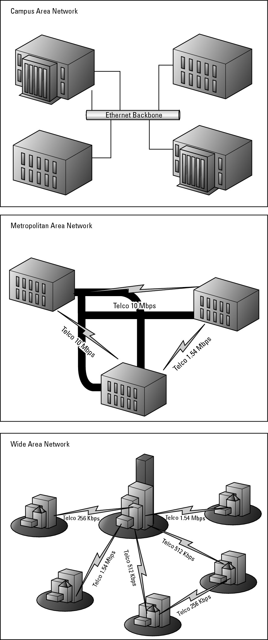
I spend a fair amount of time in this book talking about Local Area Network (LAN) technologies and devices, with a comprehensive look at LAN technologies in Book III, Chapter 1. A LAN is a private network that typically is made up of a well-connected, reliable, and fast network connection. A WAN is a type of LAN. Alternatives on the LAN framework include CANs, MANs, and WANs. All three of these network options are illustrated in Figure 1-1.
CANs
If you take the LAN network model and make it slightly larger, you end up with several buildings in a single area that are interconnected. This kind of network is referred to as a campus environment or a Campus Area Network (CAN). In this case, the interconnections between the buildings may be provided by internal resources or by a telephone company or service provider. In most cases, the interconnection of these buildings is a private investment in a network infrastructure because these links will be used indefinitely.
If you use external network providers, you can still refer to this infrastructure as a WAN. However, because the network is typically a private network structure, many organizations refer to it as a LAN. This LAN may be a flat network with switches connecting all of these buildings on a campus or the floors of a building, but because you want to reduce broadcasts spanning your entire network and passing though remote buildings, you probably will implement a series of routers. These routers perform better than switches when managing network traffic and conserving bandwidth for other applications.
MANs
If your buildings are more dispersed, say around a city, your network increases to a Metropolitan Area Network (MAN). In this case, the odds are very high that you will not own the entire network infrastructure, so you will be buying or leasing network connectivity from a service provider. Because your network connections are fairly short range and may all be hosted by one provider, the technology choices may allow you to utilize higher speed or cheaper technologies over traditional WAN technologies. These choices are entirely dependent on what your service provider can offer.
WANs
Finally, you get into Wide Area Network (WAN), using traditional WAN connectivity options such as Frame Relay and switched circuits. These technologies allow you to create a multi-location LAN, or WAN, that could span the globe. In that case, you are dealing with and negotiating connections in many countries and getting all of your service providers or telephone companies to communicate with each other, so you probably need to rely on a routing protocol to deal with the changing link states and network availability.
Figure 1-1: Comparing CAN, MAN, and WAN.
Choosing Technologies
When you are choosing technologies, you are at the mercy of your service provider, but the provider probably will give you a menu of options to choose from, each with different performance characteristics and prices. Your choices will include an array of physical connection types, which includes technologies such as frame relay or T1 connections. After you have selected a physical medium of connection, you also must choose from myriad routing protocols, including Routing Information Protocol (RIP) and Open Shortest Path First (OSPF).
![]() Revisit your technology choices every few years, because your provider or its competition may be able to give you more performance from less expensive connections.
Revisit your technology choices every few years, because your provider or its competition may be able to give you more performance from less expensive connections.
Getting the physical connection
In almost every connectivity option, you will be using a router to act as the boundary between your network devices and the devices that belong to the telephone company. In many cases in this scenario, you may use two routers, where, as part of your contracted connection, the telephone company provides you with a router that connects directly to your router. In other cases, you may use a router that is supporting T1, ISDN, or another connection type through a WAN Interface Card (WIC), which is an expansion card for your router, allowing your router to connect directly to the telephone company’s network. Figure 1-2 shows a router that contains a T1 WIC.
Figure 1-2: Cisco WIC, installed in a router.
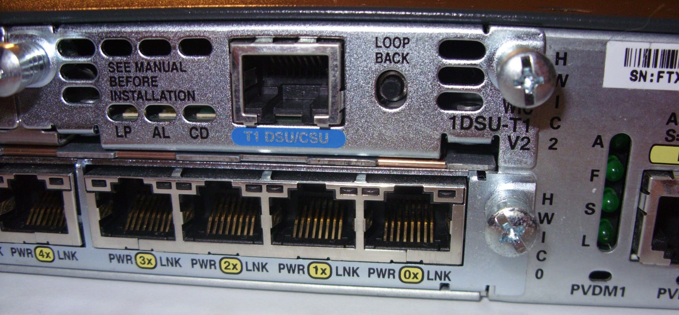
Depending on your router’s capabilities and the telephone company’s connection options, you may use a Data Service Unit/Channel Service Unit (DSU/CSU), which is a Layer 1 device that connects the telephone company’s network to your router. In Figure 1-2, the DSU/CSU is built into the T1 WIC, whereas in other cases, you will have separate, distinct devices connected to your router. The DSU/CSU can be thought of as a modem in that it connects your digital device (router) to your telephone company’s network; however, unlike a modem, the connection is digital on both sides of the DSU/CSU. When the DSU/CSU is a separate device, it typically connects to your router through a serial port.
Here are some of the options to consider for connecting your network to a telephone company’s network:
• Cable: Many cable companies have gotten into the service-provider market, with the least expensive of their connections being their standard cable connection. In recent years, these companies have started offering faster and more reliable connection options such as fiber-based services like FiOS.
![]() Because these companies are fairly new in the market, they tend to have more modern connection options, which may present challenges when setting up a WAN spanning borders of less technologically developed countries.
Because these companies are fairly new in the market, they tend to have more modern connection options, which may present challenges when setting up a WAN spanning borders of less technologically developed countries.
• DSL: DSL technologies are fast and reliable options when newer options are not available. They have been around long enough to be available in most regions and tend to offer inexpensive connectivity options. This technology changes rapidly. Your local provider supports some DSL types, such as Asymmetric Digital Subscriber Line (ADSL) or Symmetric Digital Subscriber Line (SDSL).
• T1/E1/ISDN: ISDN and T1 connectivity options are typically more readily available than even ADSL because of their level of maturity in the overall network world. T1 connections and Primary Rate Interface (PRI) ISDN connections allow you to put a full, 26-wire pair connection into place and then activate as many pairs of wires as you need, providing you with 64 Kbps per pair. This partially activated connection is called a fractional connection.
The standards on the number of pairs and the speeds vary by region. In the United States, typically you are looking at 24 pairs on a T1 connection with an 8K control channel, yielding 1.544 Mbps of throughput; whereas the European versions (E1) usually provide 32 pairs, providing a connection of 2.048 Mbps. The North American T-Carrier signals go up to five levels, with the top end being 5,760 pairs or channels allowing 400.352 Mbps of throughput. Although these numbers get pretty high, Basic Rate ISDN (BRI ISDN) will run as little as two 64 Kbps data channels with a 16 Kbps control channel.
• Serial connections: Serial connections are the oldest connection technologies and are available in areas that may be lacking other connection methods. Serial connections are available worldwide. The frame relay system is the main method of offering serial connections. When implementing frame relay on a Cisco router, you have two choices for encapsulation methods: Point to Point Protocol (PPP) or High-Level Data Link Control (HDLC), which are discussed in Chapter 5 of this minibook. Your choice depends on what you are using at the other end of the connection, because the same technologies must be used at both ends of the connection.
With the physical part of the connection out of the way, your next choice deals with routing protocols.
Choosing a routing protocol
The one option that is always available when choosing a routing protocol is to not choose one and to use manual routing management. Although manual routing is an option, it is not always a good option. Manual routing is easy to set up if you understand your network, but as your network grows from 2, to 4, to 10, to 100 routers, implementing changes may become so difficult that you stop making them, thus penalizing your users with poor network management. So, even though you have the option of manually maintaining all of your routing tables, you probably want to investigate a dynamic routing protocol as your network grows.
Not all routing protocols are equal, and each has a benefit and a drawback. Although you see the configuration and management of each of these protocols in later chapters of this minibook, as specified in the following list, I introduce you to each of them in later sections of this chapter:
• Routing Information Protocol (RIP) version 1 and 2 are covered in Chapter 7.
• Enhanced Interior Gateway Routing Protocol (EIGRP) appears in Chapter 7.
• Open Shortest Path First (OSPF) is configured in Chapter 8.
• Intermediate System to Intermediate System (IS-IS) is described in Chapter 8.
• Boarder Gateway Protocol (BGP) appears in Chapter 9.
Routing Information Protocol (RIP)
RIP as a routing protocol is based on methodologies that go back to the beginning of TCP/IP routing with the formation of the ARPANET, which is the precursor of what is now called the Internet. RIP is an open protocol and was first published in RFC1058 (and its successor RIPv2 in RFC1723), which was later adopted as Internet Standard 34. RIP is a distance-vector routing protocol, which means that each router may not know where the final destination network is, but it does know in which direction it exists and how far away it is.
![]() By direction, I mean which routing interface the router will send data through, and by how far away or distance, I mean how many routers the data will pass through before reaching its destination.
By direction, I mean which routing interface the router will send data through, and by how far away or distance, I mean how many routers the data will pass through before reaching its destination.
RIP places a limit on the maximum distance to the targeted computer as 16 hops or 16 routers, with each router representing a hop from one network to another. Because the route starts with router 0, you are dealing with routes that touch 15 or fewer other routers. For routers farther away, the routing information is dropped or ignored. You may think that 16 hops is a limitation, but even on a network as large as the Internet, you can usually get to where you want to go within 16 hops. When you traceroute (tracert on Windows) an address, traceroute traces for only 30 hops, and in most cases, it gets you to your destination in fewer than 15 hops. To accomplish this efficiency requires a high level of network planning to ensure that your hop counts are as low as possible.
In terms of sharing routing information with others, RIP version 1 (RIPv1) shared its routing information with other routers by broadcasting its routing table information through all of its configured network interfaces. Each router that received this information stored it in its own routing table with updated hop counts, ignoring or dropping hop counts over 15.
One major issue that RIPv1 had was that it was classful, which meant that all network segments on a network had to be the same size. You could not deviate your subnet mask from the default for the class; all network segments needed to use the same mask. Figure 1-3 illustrates this problem in a three-router layout, with five segments, where only the three segments have computers. If you were to use a Class C address space like 192.168.1.0, your mask would have to be 255.255.255.224, which would give you 8 segments of 30 devices; but in case of RIP, you would be able to use only 6 segments, and one of your 30 devices would be the router’s interface, leaving you with 29 devices on the network segments. When sending routing information, only the network IDs are sent and not the matching subnet masks.
To deal with some of the limitations of RIP version 1, RIP version 2 (RIPv2) was proposed in RFC1388 and updated in RFC2453, which became Internet Standard 56. RIPv2 allows the protocol to carry subnet information, allowing support of Classless Inter-Domain Routing (CIDR), which ignores class-based boundaries when routing and allows each segment to maintain a unique subnet mask. The topic of CIDR and subnetting is covered in Book II, Chapter 1.
Figure 1-3: RIPv1 and subnetting.

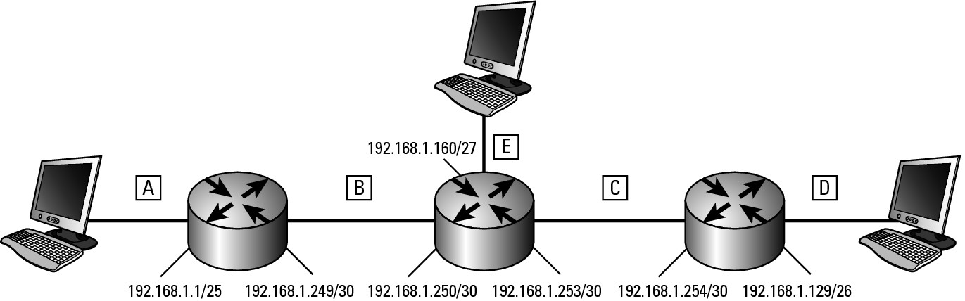
Without needing to maintain the same subnet mask on all network segments allows conservation of network IP addresses, as shown in Figure 1-4; where an updated network addressing layout exists with appropriate subnet masks on each segment. In this case, you can assign a larger network ID to segment A (192.168.1.0/25) of 126 hosts; a smaller segment D (192.168.1.128/26) of 62 hosts; and a smaller segment E (192.168.1.192/27) of 30 hosts; while assigning smaller addresses spaced to segments B and C of 192.168.1.248/30 and 192.168.1.252/30. You are left with two other small address blocks of 192.168.1.224/28 allowing 14 hosts and 192.168.1.240/29 allowing 6 hosts. In this scenario, you waste few addresses because the router-to-router segments have only the minimum number of addresses assigned to them (2), whereas previously you had two wasted segments of 16 addresses, plus the router-to-router segments that were allocated 14 addresses, when they needed only 2.
Figure 1-4: RIPv2 and subnetting.
RIPv2 also switched from using broadcasts to propagate router information over to using multicasts at address 224.0.0.9, thereby reducing network traffic to unneeded systems. To further enhance the protocol, router authentication (to validate the router’s participation in RIP) was added so that only routing data from trusted routers is added to the routing tables, thereby preventing corruption of the routing tables from unauthorized routers on your network.
With the advent of IPv6, RIP was given another facelift in the form of RIP next generation (RIPng), which increases the size of the address fields, and changed the authentication mechanism to IPSec.
Enhanced Interior Gateway Routing Protocol (EIGRP)
If the world can create a protocol by consensus, you could likely build a better protocol, because you would not need to make concessions with other people. Cisco created the now obsolete Interior Gateway Routing Protocol (IGRP) to overcome issues in RIP. IGRP was still a distance vector routing protocol, but in addition to distance, Cisco allowed the protocol to carry more information about the path, such as bandwidth, delay, load, MTU, and reliability. Cisco also increased the maximum hop count to 255 but allowed it to be configurable.
Rather than broadcasting updates every 30 seconds, IGRP stretched the time out to 90 seconds, reducing load on the network but increasing convergence time.
As with RIPv1, IGRP is a class-based routing protocol, and the data about the routes does not include subnet mask information. Because of the limitations of the protocol, it too has been replaced by a better, newer version in the form of Enhanced Interior Gateway Routing Protocol (EIGRP).
EIGRP reduces the time to convergence by passing data to other routers only when neighboring routers change. If there is a new adjacent router, EIGRP will pass that information out to all of its routing partners or out to all of its network interfaces.
EIGRP stores its routing information in the router in three basic tables:
• Neighbor table: This table stores the addresses of neighbors, those routers that are directly accessible through the routers own local interfaces. If the path to a targeted router has to go through another router, then that targeted router is not a neighbor.
• Topology table: This table stores the routing tables which this router has received from neighboring routers. With this information, this router identifies the best route to each possible destination network, as well as identifying a successor and a feasible successor. The successors will be used when the primary route to the destination fails.
• Routing table: This table is built from the topology table and contains just the routing information to each destination network. It includes successors as the primary route to the destination and feasible successors as backup routes where applicable and depending on the configuration of EIGRP.
Open Shortest Path First (OSPF)
OSPF is a link-state routing protocol, as compared to the distance vector protocols you have been looking at. The main difference here is that a linked-state protocol does not send its routing table in the form of updates, but only shared its connectivity configuration. By collecting connectivity information from all of the devices on the network, OSPF can store all this information in a database and use that information to build a topology map. This information will allow OSPF to identify the best or shortest route to every other network segment on the network. The route selection is based on overall hops to the destination, as well as link speed or link cost. The topology not only includes the best route to the destination as calculated by the Dijkstra algorithm (a search algorithm created by Edsger Dijkstra), but also, when possible, it includes a candidate or backup route to the destination.
After creating the topology map, OSPF populates the routing table with the chosen routes to each destination. As traffic passes from router to router, each router evaluates the best path to the destination network. In some cases, this process can lead to routing loops on the network, because each one is evaluating the path based on its own link state database.
The OSPF interior network protocol belongs to a single routing domain (or group of routers) known as an Autonomous System (AS). All routers belonging to the same AS share connection information and build their linked-state database from that information. Specifically with OSPF, as opposed to link-state terminology in general, the primary, or best, route the destination goes through is the Designated Router (DR), although if it fails, the secondary or backup path will be sent to the Backup Designated Router (BDR).
OSPF typically uses multicast to share connection information with its neighbors, and this information is sent to the 224.0.0.5 multicast address.
OSPF is an open protocol and is defined in RFC2328 for version 2 of the protocol. Version 3 of OSPF has been updated to support IPv6 and is defined in RFC5340. Other than for the newly integrated support for IPv6, no major technical differences exist between version 2 and version 3.
Intermediate System to Intermediate System (IS-IS)
IS-IS is another link-state routing protocol, and its technical information is found in RFC1142. It was developed by Digital Equipment Company for DECNet at the same time Internet Engineering Task Force (IETF) was working on OSPF for IP. As such, they do share some similarities in purpose. Since being developed, IS-IS has been extended to support IP and was published as an open standard in RFC1195.
IS-IS is used primarily by service providers on their network to route data, so you will not likely see it or have to work with it. One major difference between IS-IS and other routing protocols is that IS-IS does not rely on IP to distribute routing information traffic. IS-IS, which is independent of the network layer protocols being used, uses any network layer protocol to send its messages; in addition, IS-IS can distribute routing information for any protocol, not just IPv4, which simplified updating the protocol to support IPv6.
IS-IS works with two basic areas, a Level 1 (intra-area) or Level 2 (inter-area). A third area designator is a hybrid Level 1–2 (both areas). Each IS-IS router is only ever part of an area, but Level 1–2 routers can exchange information with routers in both areas. Within an area, the methods that IS-IS uses to manage routing information is similar to that of OSPF.
Border Gateway Protocol (BGP)
BGP is one of the core protocols used by most of the service providers on the Internet. Most core routing decisions on the Internet are made by BGP. The current version (version 4) of the protocol is defined in RFC4271.
BGP can run as either an interior or exterior protocol, and when run as an interior protocol, it may be referred to as IBGP.
As an exterior protocol, BGP’s main role is to transmit to other BGP routers any routes being managed by an interior gateway protocol, thereby allowing the routes to be used by all systems in both areas.
To identify the systems for which BGP is supposed to be transferring routing information, BGP makes use of Autonomous Systems (AS) which are groups of routers on your network.
![]() In most cases, you will need to implement this protocol only when attempting to provide redundant routing between you and your service provider.
In most cases, you will need to implement this protocol only when attempting to provide redundant routing between you and your service provider.