
Chapter 2: Exploring Cisco Network Design
In This Chapter
![]() Checking out Cisco’s three networking methodologies
Checking out Cisco’s three networking methodologies
![]() Wading through the layers of Cisco’s networking model
Wading through the layers of Cisco’s networking model
![]() Reviewing the benefits of these methodologies
Reviewing the benefits of these methodologies
Networking devices can be a complex task to get just right. Although anyone can plug two devices together, doing so randomly without thinking through the connection’s affect on the whole can produce a network with a less than desirable performance — or bring the entire network to a grinding, screeching halt.
This chapter identifies the methodologies that help you create stable and reliable networks, including how Cisco designs networks and the building blocks that Cisco uses to divide networks. Rather than designing the network as a single entity, Cisco breaks the overall network down into components, and designs each component separately, which makes up the network building blocks or modules. Because reviewing many of these topics in detail would involve several volumes of text, I focus on the most important principles that are necessary to make informed decisions about your network design.
By modularizing the network, you simplify how you work with and identify the components that make up your network. To start using this methodology, you may need only to make a few changes to your network, but it usually takes a shift in the way you think of your network and its devices. By looking at each section of specialization in network components, you can work in each section to identify issues, modularly grow or scale the network size, and simplify troubleshooting network problems by limiting the scope of the problem domain.
Embracing Methodologies
Cisco networking relies on three main design methods when dealing with network design or network layout. The first two methods in the following list relate to the goal of the network, whereas the third is an overall deployment method. Here are the three methods:
• Intelligent Information Network (IIN): The IIN framework can help add intelligence to your network. This intelligence spans layers of the network and links it to the rest of your IT infrastructure. If you consider that the network is simply a conduit that allows information from business applications to move from one application or location process to another, the design of the network ensures that the business processes that require this information will have it available when needed.
• Service-Oriented Network Architecture (SONA): The SONA framework takes a traditional network structure and helps it to evolve into an IIN. SONA assumes that your network will be unified, and that all data will traverse a single network architecture.
• Prepare, Plan, Design, Implement, Operate, and Optimize (PPDIOO): PPDIOO is a lifecycle method that Cisco uses for network management. Following this lifecycle management process assists in lessening the total cost of ownership for the network, increasing network availability, and improving agility to make changes to the network structure.
Each method has a place in the implementation of your networking solution. SONA gives you a structure to follow, allowing you to implement the IIN framework, while PPDIOO is a deployment model to follow when implementing any network changes, regardless of what the driving forces were for those changes.
Intelligent Information Network (IIN)
Your IT infrastructure includes not only your network, but also applications, servers, and services. The concept behind IIN is that network design should make information available when it is needed by business processes. To illustrate this concept, try drawing your network diagram, but rather than starting with something like a firewall, router, or switch, start the diagram with a business process, such as purchase a widget. The diagram needs to include the business logic and procedures that are involved in the process, as illustrated in Figure 2-1. The diagram then may branch out into the pieces of IT infrastructure that are used for this process, ending with how these IT components actually communicate.
Figure 2-1: Widget purchase process.
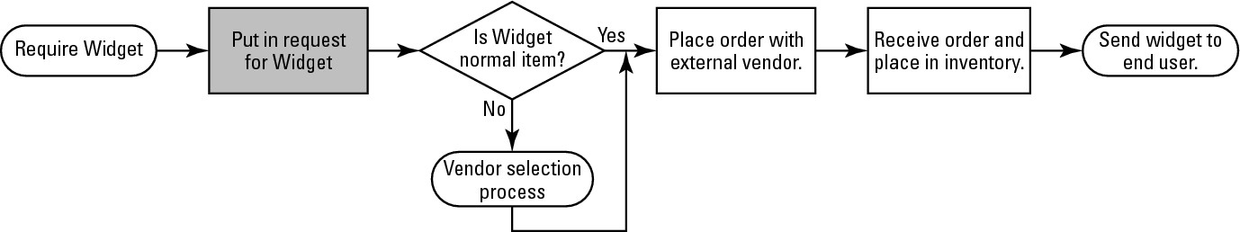
Taking this inclusive design approach allows you to see which IT components may need to be connected with higher-speed links or implemented with additional redundancies (such as backup systems or connections), rather than concentrating solely on the network as a separate entity. The three main points are
• The network as an integrated system
• Active participation of the network in service delivery
• Enforcing business processes through network rules
Here are the three points of integration, or the points on your network where you can add IIN components:
• Integrated transport: Involves the integration of network data, such as voice, data, and video. These components make up the Cisco Unified Network, which places these three main traffic types (voice, data, and video) on it, while allowing each to be optimized for usage through traffic management features.
• Integrated service: Takes common network elements, such as storage and servers, into account and allows for the function of business services in case of a local network failure. The ability to provide backup (or redundant) services is due in part to virtualization technology for servers as well as storage and network components, which allow for these services to be maintained in multiple physical locations at the same time.
• Integrated application: Allows the network to be aware of the applications that are running on it. When the network is application-aware, it can integrate network features to optimize data movement, implement security, and provide redundancy.
Service-Oriented Network Architecture (SONA)
The SONA network architecture contains three basic layers, as shown in Figure 2-2:
• Network infrastructure layer: Contains the enterprise network architecture, which includes switches, routers, communication links, and so on. This layer has redundancy built into it and contains network layer security to enforce business policies as needed. The components at this layer are discussed later in this chapter, and represent the components that map directly to the OSI model discussed in Book I, Chapter 1.
• Integrated service layer: Virtualizes services (or unties them from specific pieces of hardware) to allow them to be provided over a dispersed or centralized network environment. The following services are provided at this layer:
• Identity: Authentication services for user or device credentials, which can play a role for network or application access.
• Mobility: Allowing access to network resources from any location. This may rely on wireless technologies or a Virtual Private Network (VPN).
• Storage: Storage of important network data and replication or duplication of that data, over the network, to remote locations for disaster recovery.
• Computing or processing: Servers represent the main element of this component, while virtual servers allow for scaling and betting utilization of server processing power.
• Security: Security for your business is crucial, and the security level makes use of security features at the network level, such as intrusion detection and prevention systems (IDS and IPS).
• Voice and collaboration: Voice services now run over the main corporate data network, and have allowed for more options for users to communicate. These communication methods include the traditional telephone, but also include instant messaging and collaboration through websites, such as Microsoft’s SharePoint.
• Application layer: Carries the responsibility for providing the applications that users rely on. These applications include the following product areas:
• Customer relationship management (CRM): Communication with clients, as well as all of their pertinent data, can be found in CRM applications.
• Enterprise resource planning (ERP): Business data for your organization is found in your ERP system. This is everything that would have been in a traditional accounting system, plus information on business processes and business logic, thereby allowing you to derive more planning and statistical information from the accounting system.
• Procurement: Purchasing can sometimes be tracked as part of the overall corporate ERP system, or can be a standalone system to manage purchasing from the request for a quote through to the deployment of the purchased product to the end user.
• Supply chain management (SCM): Procurement systems can purchase items, but SCM systems tell procurement what parts need to be purchased and when. In manufacturing and service organizations, good SCM systems will provide you with “just in time” inventory items right before you need those items.
• Instant messaging (IM): Instant messaging has come into businesses who now expect to be able to instantly communicate within their network infrastructure. This assists in users on your network in their collaboration goals.
Figure 2-2:
The composition of the SONA framework.

• Unified messaging (UM): Unified messaging talks all of the forms in which users can communicate and ties them together, allowing for unique situations, such as where an e-mail can be relayed to office voicemail, and then forwarded to a cell phone as a text message. Unified messaging takes control and integrates all communication and messaging formats within an organization, either partially or completely.
With each layer separate, you can focus on the applications that need to be supported in your organization, because not all applications on your network may be classified as critical to business operations. What the critical applications are will vary from company to company based on their specific business needs for those applications, so the business requirement for the application is used to determine the requirements for the supporting network components. In most cases, the application does not care specifically how things work. Instead, the application has a requirement for a specific feature, such as identity services. That feature can then be provided by something like Remote Authentication Dial In User Service (RADIUS) authentication against a user account database, which is stored in the Microsoft Active Directory (AD). The application does not care where the user information is stored, just that it can request authentication. At the same time, the RADIUS server does not care that the network link between itself and the AD server has to go over Wide Area Network (WAN) on two load-balanced connections.
![]() I find it surprising how many companies have IT departments that implement technology for the sake of technology, and lose sight of the fact that they are in the business of providing support for the company by supporting their applications. So the application and its requirements should be the driving force for network changes, and not the fact that new and cool technologies are available.
I find it surprising how many companies have IT departments that implement technology for the sake of technology, and lose sight of the fact that they are in the business of providing support for the company by supporting their applications. So the application and its requirements should be the driving force for network changes, and not the fact that new and cool technologies are available.
![]() The SONA framework provides scalability because it is modular, availability because of its redundancies, manageability through deployed tools, and efficiency by maximizing resource utilization.
The SONA framework provides scalability because it is modular, availability because of its redundancies, manageability through deployed tools, and efficiency by maximizing resource utilization.
Prepare, Plan, Design, Implement,
Operate, and Optimize (PPDIOO)
You can step into the system described in the following sections at any point for your own network. In this instance, I start with deciding whether to implement a new network or to upgrade an existing network. When looking at Figure 2-3, you will notice that these elements form a never-ending circle, because the optimize step will typically identify changes, which can lead to better performance on your network, which then initiates a new prepare step.
In the following sections, I take a closer look at each phase.
Figure 2-3: The cyclical structure of PPDIOO life cycle.

Prepare
During the Prepare phase of the process, examine the overall business requirements and develop a strategy for the network. You may also examine the technologies required to support the network environment you envision. The end goal in this phase is to create a business case to justify the cost of deploying the network changes.
When identifying the customer requirements, determine and document the following key items:
• Network applications and services: Knowing what network related applications and services are currently being offered to users of the network is critical in planning the design of the network, because you will need to know what the offerings are and where users of these offerings are to be located. In addition to the applications and services that are currently on the network, you will need to know what new applications and services will be implemented over the life of the current network design. Your network design life will often be the life of the networking components, so if your organization replaces all technology in a three to five year cycle, then you will want to plan for expected changes in that time frame. With that timeframe in mind, will the network be supporting streaming video, Voice over IP (VoIP), or video conferencing? This will influence your overall network design.
• Organizational goals: Design of the network will be in support of the overall organizational goals. These goals will vary from organization to organization, but may include goals such as reduce costs, improve customer interaction, add new services for customers, and improve competitive position in the market. With these goals in mind, you may choose to focus effort and money on certain areas of the network and network design.
• Organizational constraints: Every organization has constraints on what they can or cannot do. The one constraint that almost every organization has is money, so if there are no other constraints on you as the network designer, there is likely a budget that you need to operate within. Other constraints may be placed on an organization due to schedules, internal policies, or government regulations. These may all play a role in the overall network design, and knowing about them at the start of the design process prevents the need to redesign after the fact.
• Technical goals: Unlike the organization’s goals, the technical goals tend to focus on technology, whereas the organization goals focus on business operations. However, these two sets of goals are not mutually exclusive. When examining the organizational goal of improving customer interaction, technical goals that would align with the organizational goal may be to improve website access and reliability, implement VoIP infrastructure, or reduce network response time. Other technology goals may be related specifically to the technology, such as modernize antiquated technologies, simplify management of technology, or reduce equipment failures.
• Technical constraints: Technology within the organization may also put limitations on what you can accomplish within your network design. Some examples of technology constraints include existing wiring limit network throughput and support for legacy networking equipment.
Plan
The Plan phase allows you to examine the network requirements needed to deploy the business services or applications defined in the Prepare phase. This may require using network management tools to examine the current network and classify its current level of services, resiliency, and performance.
The goal at this phase is defined by the organizational and technical goals, and an analysis of the gaps in that list (or gap analysis)— and how to fill those gaps— is the intended results. After you complete the Plan phase, you know the current state of the network as well as any identified shortcomings that you need to resolve.
Gathering Information
The information gathered in the Plan phase is critical in knowing how your network devices currently perform.
When you gather information about the network in the Plan phases, consider the following as sources of information:
• Current sources for documentation of your current network structure and configuration
• Results of a new network audit using exiting documentation and auditing or network performance tools
• Results of a new traffic analysis study using live data captured from an existing network
Cisco data gathering command-line tools
If you currently have Cisco devices, you can gather a plethora of data using commands, such as the following:
![]()
show tech-support
![]()
show processes cpu
![]()
show version
![]()
show processes memory
![]()
show running-config
Although these commands may not mean anything right now, as you progress through this book, I show you how to run these commands and many others, starting in Book I, Chapter 5. As a brief example, the show version command run on a router named Router-1 yields the following output with the software version, system uptime, system software filename, processor type, the number of network interfaces, additional expansion modules installed, the amount of RAM, and the amount of flash memory:
Router-1#show version
Cisco IOS Software, C2600 Software (C2600-ADVIPSERVICESK9-M), Version 12.3(4)T4, RELEASE SOFTWARE (fc2)
Technical Support: http://www.cisco.com/techsupport
Copyright (c) 1986-2004 by Cisco Systems, Inc.
Compiled Thu 11-Mar-04 19:57 by eaarmas
ROM: System Bootstrap, Version 12.2(8r) [cmong 8r], RELEASE SOFTWARE (fc1)
Router-1 uptime is 7 minutes
System returned to ROM by power-on
System image file is “flash:c2600-advipservicesk9-mz.123-4.T4.bin”
This product contains cryptographic features and is subject to United
States and local country laws governing import, export, transfer and
use. Delivery of Cisco cryptographic products does not imply
third-party authority to import, export, distribute or use encryption.
Importers, exporters, distributors and users are responsible for
compliance with U.S. and local country laws. By using this product you
agree to comply with applicable laws and regulations. If you are unable
to comply with U.S. and local laws, return this product immediately.
A summary of U.S. laws governing Cisco cryptographic products may be found at:
http://www.cisco.com/wwl/export/crypto/tool/stqrg.html
If you require further assistance please contact us by sending email to
Cisco 2621XM (MPC860P) processor (revision 0x300) with 125952K/5120K bytes of memory.
Processor board ID JAE081160XR (3618058385)
M860 processor: part number 5, mask 2
2 FastEthernet interfaces
1 Virtual Private Network (VPN) Module
32K bytes of NVRAM.
32768K bytes of processor board System flash (Read/Write)
Configuration register is 0x2102
Gather tools to get more information
The information found in the Cisco network devices can be comprehensive regarding configuration information and can provide some level of performance data. However, these devices can be lacking in many areas, such as historical trending, outage history, and traffic patterns. To deal with this, you need to use other tools to give you this other information. The following are just some of the tools you might want to use:
• CiscoWorks: Cisco’s configuration and auditing toolset allows you to create and apply configuration changes to all your network devices, plus it provides you with a monitoring toolset to see the status of your network devices. More information can be found about CiscoWorks from www.cisco.com/en/US/products/ps11200/index.html. CiscoWorks is priced depending on the size of your network, with the smallest network size (50 or fewer devices) has a cost of approximately $2,000, but if you want to kick the tires on CiscoWorks, then head to the Cisco website and download an evaluation copy.
• WhatsUp Gold: Ipswith’s network-device monitoring tool, which is capable of discovering network devices, tracking system health, and receiving Simple Network Management Protocol (SNMP) trap and Syslog data. Ipswitch provides a 30-day evaluation of the product, whose price starts around $1,500 for the ability to manage 25 devices. Check out their website at www.whatsupgold.com.
• Multi Router Traffic Grapher (MRTG): Open source Round Robin Database (RRD)–based network monitoring and graphing tool used to show current and historical information about network devices, specifically router and switch interface statistics. This tool is freely available from oss.oetiker.ch/mrtg/index.en.html.
• Cacti: Open source RRD–based network monitoring and graphing tool. If you have used MRTG but wanted something a little flashier or geared towards other types of devices, then Cacti may be for you. Cacti makes it easier to add devices such as servers to your monitored devices list. As with MRTG, this tool is freely available, and you can find it for download on their website, www.cacti.net.
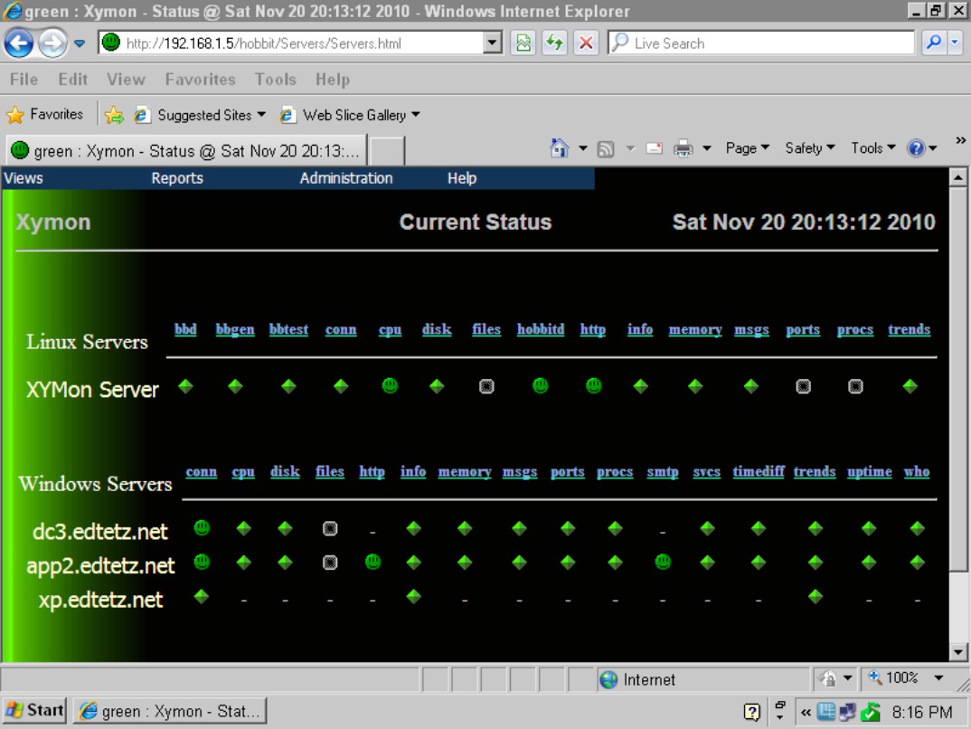
• Xymon Monitor (formerly Hobbit Monitor): Open source–device monitoring and alerting tool, as shown in Figure 2-4, that displays current status information for network devices. Like Cacti and MRTG, Xymon is capable of gathering a wide range of information about your devices and offers historical information on those devices in the form of RRD–based charts. One difference with Xymon lies in its ability to send out alerts to configured users in the event that certain conditions have been met, such as a device has gone offline for more than 5 minutes or free disk space on a server has dropped below 100 MB. You will find Xymon on its Sourceforge page at xymon.sourceforge.net.
• Wireshark: Open source packet capture and analysis tool that is capable of collecting complete network data information from your network, allowing it to be reviewed in great detail. The data Wireshark collects are the data packets that pass by the computer performing the capture. After capturing this data, Wireshark can provide you with statistical data such as the most talkative network devices. This tool is freely available from their homepage at www.wireshark.org.
• NetFlow: A Cisco Internetwork Operating System (IOS) component (the Cisco IOS operating environment is discussed in Book I, Chapter 5) that collects and measures data as it flows through switch and router interfaces. While NetFlow on a switch or router collects data, it does not provide any of the analytical functions. For analytics, you will require a NetFlow collector.
• Cisco NetFlow Collection Engine: Cisco’s NetFlow gathering and analysis tool that collects NetFlow data from network devices and allows for centralized analysis of the data. This data can be analyzed across the network to ensure that application data is passing over the network in a manner that is appropriate to the application. For example, you could use this tool to ensure that a business-critical accounting system is not being impacted by users watching YouTube videos. You can get more information about the NetFlow Collector Engine from www.cisco.com/en/US/products/sw/netmgtsw/ps1964/index.html, but be
prepared — this product comes with a price tag in excess of $16,000. Other products such as WhatsUp Gold are capable of performing less exhaustive NetFlow analysis.
Figure 2-4: Xymon provides up-to-the-minute statuses on any of your network resources.
Using tools to monitor the health of your network
When using these tools, review the health of your network based on some of these criteria:
• Ethernet segments must be less than 40 percent sustained utilization.
• All segments that are added to the network should be switched (using switches) rather than shared (using hubs). Switches and switching are covered in Book III, Chapter 2.
• WAN links must be less than 70 percent sustained utilization.
• Response time between local systems must be quicker than 100 milliseconds (ms).
• Less than 20 percent of traffic per segment should be broadcast (sent to all network devices) or multicast (sent to large groups of network devices).
• Cyclic redundancy check (CRC) errors must be less than one per million bytes of data.
• The rate of packet collisions on Ethernet segments should be less than 0.1 percent.
• Device CPU utilization should be less than 75 percent for sustained intervals.
• Queues should be less than 100 for output and 50 for input.
Design
After you complete the Plan phase, you know where you currently stand on the network and where you need to be. The Design phase defines what needs to be changed, removed, or added to the existing network. This includes creating network diagrams, building devices lists, and determining which high-level configuration options (such as the routing protocol, router placement, and main protocol options) will be implemented or required for the devices.
After completing this phase for many clients, it no longer surprises me the level of documentation that my clients maintain. This documentation ranges from nothing (or next to nothing) to very complete (with fully documented diagrams).
![]() In a perfect world, everyone would have complete documentation about all aspects of their network, but in most cases, even the most complete documentation has some aspects that are either out of date or missing. You can usually expect to need some level of information gathering during other phases that you then review during the Design phase.
In a perfect world, everyone would have complete documentation about all aspects of their network, but in most cases, even the most complete documentation has some aspects that are either out of date or missing. You can usually expect to need some level of information gathering during other phases that you then review during the Design phase.
Network destination addresses
When sending data over the network, the data is marked with a destination data link or Layer 2 address. The destination address will fall into one of three categories:
![]() Unicast: Unique address that will match the data link or MAC address of one network card on the network. The only network device that will read or process this network frame will be the device with that matches the data link address.
Unicast: Unique address that will match the data link or MAC address of one network card on the network. The only network device that will read or process this network frame will be the device with that matches the data link address.
![]() Multicast: Group address that does not match any data link or MAC address on your network. Any network devices on your network that belong to a data link address group will read or process this network frame.
Multicast: Group address that does not match any data link or MAC address on your network. Any network devices on your network that belong to a data link address group will read or process this network frame.
![]() Broadcast: Special group address that automatically includes all member devices on the current data link or network segment. Any network frames that are sent to the broadcast address will be read or processed by every device on that network segment.
Broadcast: Special group address that automatically includes all member devices on the current data link or network segment. Any network frames that are sent to the broadcast address will be read or processed by every device on that network segment.
Implement
Following the Design phase is the Implement phase, which puts the design into action. This phase is where you remove, add, or reconfigure devices on the network. Because this phase impacts data moving on the network (for example, if you unplug a server from the network, people cannot communicate with it), you must plan the changes, determine outage times, communicate outage or migration issues, plan rollback steps, and manage the network changes. As a change is implemented, you must test it to ensure proper operation; after a system that has been changed has passed the test, it is ready to be moved into the Operate phase.
Before performing the full implementation of your new design, first perform a pilot or prototype in a smaller, controlled environment so that you can test the new design on a few computers before rolling it out to the whole network and waiting for the IT help desk requests to shoot through the roof. If new equipment is being implemented in the core of the network, this equipment needs to be configured to the deployment specification, and a simulated network traffic load needs to be placed on the test network to identify potential real-world issues prior to the live deployment. This test may take place in a prototype test bed or with a small pilot deployment that affects only a subset of all the users on the network.
Pilot versus prototype
The two main methods of testing a network design prior to rolling out a full deployment across your network are to use a pilot or a prototype.
![]() When conducting a pilot test, you choose a small section of your network to perform the upgrade or change. The choice of location will depend on the type of network changes you are conducting, as well as the structure of your network. In some cases, the pilot area may be a branch office or a floor of your building. With the pilot, you have limited the size of the deployment, thereby limiting the number of users affected by the deployment. If things go badly, then you have a smaller impact, and possibly more time to resolve the issue before reversing the changes. A benefit of this network testing method is that it allows you to test the network with real traffic and under a normal network traffic load; the drawback is that you may affect production users on your network during the pilot.
When conducting a pilot test, you choose a small section of your network to perform the upgrade or change. The choice of location will depend on the type of network changes you are conducting, as well as the structure of your network. In some cases, the pilot area may be a branch office or a floor of your building. With the pilot, you have limited the size of the deployment, thereby limiting the number of users affected by the deployment. If things go badly, then you have a smaller impact, and possibly more time to resolve the issue before reversing the changes. A benefit of this network testing method is that it allows you to test the network with real traffic and under a normal network traffic load; the drawback is that you may affect production users on your network during the pilot.
![]() When conducting a prototype test, you build a mock network that follows your new design. With the mock network, you must have more hardware available, which may be fine if this is being done in conjunction with a hardware replacement. The benefit of this testing method is that you can test a number of scenarios with no impact to the users; the drawback is that you need to mock up systems to communicate off the network, may miss unanticipated traffic, and will have trouble simulating high network traffic load scenarios.
When conducting a prototype test, you build a mock network that follows your new design. With the mock network, you must have more hardware available, which may be fine if this is being done in conjunction with a hardware replacement. The benefit of this testing method is that you can test a number of scenarios with no impact to the users; the drawback is that you need to mock up systems to communicate off the network, may miss unanticipated traffic, and will have trouble simulating high network traffic load scenarios.
![]() If you replace or update core network components on any network, issues will likely affect all users on the network. Therefore, if you encounter issues, be prepared to roll back the implementation to an earlier point in time using a backup. No matter how much testing you have completed and how sure you are that your configurations and device selections are correct, unexpected things can result when implementing.
If you replace or update core network components on any network, issues will likely affect all users on the network. Therefore, if you encounter issues, be prepared to roll back the implementation to an earlier point in time using a backup. No matter how much testing you have completed and how sure you are that your configurations and device selections are correct, unexpected things can result when implementing.
Operate
In the Operate phase, the network functions in its day-to-day role. The network does what it was designed to do, and data is moved from device to device. In a perfect world, your job would now be done; but wait, there is more.
Monitoring network resources is critical in this phase because monitoring can identify issues before they impact the users of the network. A great day is when you can identify a major network issue and resolve it without the network users ever being aware of it. As I mention earlier, in the Plan phase, you can run many tools on your network that capture performance counters and identify resources that are not responding on your network. These tools are critical to use during the Operate phase to assist in quickly identifying network performance and configuration issues. By saving historical data from the monitoring process, you can chart an overview of the general health of the network and take corrective actions when thresholds are reached.
Optimize
After the Operate phase comes the Optimize phase because data regarding the health of the network that you continue to collect leads to identifying
• Chronic or recurring issues with the network
• Areas where performance is not what was expected
• Areas where performance has reduced over time because of excessive network load
During the Optimize phase you review your collected network data and based on that data identify items that need additional changes. At this point, you may go back to the Prepare phase and start over to incorporate those changes into your overall plan.
![]() In some cases, these network changes just need to go through a change management process, whereas larger changes may require business cases and justification before implementation.
In some cases, these network changes just need to go through a change management process, whereas larger changes may require business cases and justification before implementation.
![]() One advantage of the PPDIOO process is that the Design phase yields a complete set of documentation related to the configuration and structure of the network. As the pilot/prototype, and implementation changes the actual deployment plan, these changes are rolled in the documentation. If this documentation process proceeds after the fact, with changes being implemented through a change management process that updates or appends to the documentation, you continue to have a fully documented network.
One advantage of the PPDIOO process is that the Design phase yields a complete set of documentation related to the configuration and structure of the network. As the pilot/prototype, and implementation changes the actual deployment plan, these changes are rolled in the documentation. If this documentation process proceeds after the fact, with changes being implemented through a change management process that updates or appends to the documentation, you continue to have a fully documented network.
![]() Full network documentation makes continued troubleshooting easier and gives new employees a running start when learning the network structure or troubleshooting issues.
Full network documentation makes continued troubleshooting easier and gives new employees a running start when learning the network structure or troubleshooting issues.
Examining the Layered Network Model
Cisco recommends implementing a hierarchical network model to
• Save money: Costs savings come from using appropriate technologies at each layer, rather than attempting to solve all problems with one routing or switching platform.
• Simplify understanding: The network can be identified by larger blocks, rather than attempting to visualize everything that takes place in a black box.
• Allow for modular growth: Because you have separated components to jobs at different layers, it is easier to upgrade or grow devices at a single layer.
• Improve problem isolation times: When troubleshooting issues, it is much easier to identify where the issue has occurred, reducing the time resolution.
By following this hierarchical model, you can treat each layer of the network as a discreet component. This allows you to focus on upgrades to separate areas rather than treating the network as a whole. With this model, you need to be concerned with four distinct areas, as shown in Figure 2-5:
• Core: The traffic flow center of the network whose main purpose is to pass data packets to and from the other layers as quickly as possible. On smaller networks, you would find your servers connected to the core, but on larger networks, your servers will exist on their own distribution and access layers.
• Distribution: Aggregates or collects data from the access layer and passes it to the core layer.
Figure 2-5: Hierarchical network model.
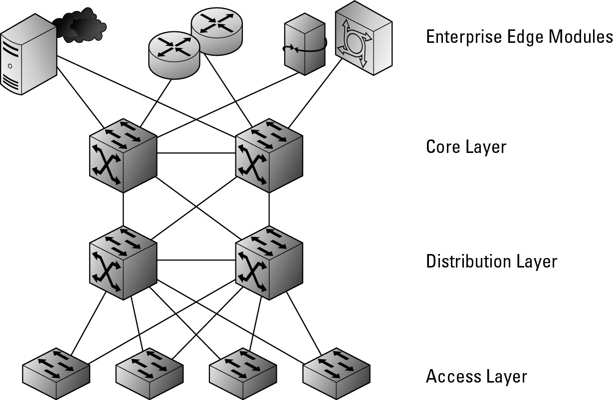
• Access: Provides connection services for end-user systems or servers (when they have their own access layer). Devices on this layer will send their data to the distribution layer in order to be processed and passed onto the core networking layer.
• Enterprise Edge: Interfaces with systems that reside outside of the main enterprise campus. The remote systems need a pathway to get onto the network, and these edge components provide that link. This may be a connection to the Internet or VPN server components granting inbound access. Unlike the rest of the network, which is under complete control of your corporation’s IT department and falls within their building, the edge components make use of external resources provided by a telco or Internet Service Provider (ISP) and grant access to systems that are not housed in the corporation’s building.
![]() Figure 2-5 shows the network model as a switched network; however, this same design may be implemented using a routed network.
Figure 2-5 shows the network model as a switched network; however, this same design may be implemented using a routed network.
Core layer
The core layer of the network is the data movement key of the data structure and focuses on the following components:
• Fast transport: The fastest interfaces available should be used for the core layer; in addition, all devices come with an internal data movement speed that can be found in the product specifications. This is as important as the speed of the external facing interfaces.
• High reliability: Due to the volume of traffic that is handled by this layer, it must be able to pass that data with very few errors. Some errors are normal on a data network. However, within the core, errors generated from this layer should be much lower than the network average.
• Redundancy and fault tolerance: In the event that there is a failure in any single device, redundancy in the design will provide you alternative paths that will allow the core of your network to continue to operate, though possibly at a reduced speed. Having redundant systems or components within a system (like backup power supplies) makes your network design fault tolerant.
• Low latency: As a network device handles data that it is moving, it introduces small delays; in the core of your network, these delays should be kept to a minimum and products or configuration options to reduce the processing time should be used.
• Avoidance of slow packet manipulation caused by filters: This is a continuation of the low latency point, in that filters on traffic, such as applying or evaluating Access Control Lists (ACLs) should be avoided because it will have an impact on the overall speed of data movement.
• Limited and consistent diameter: The diameter of your network is how many devices data must travel through to go from one point on your network to another, while travelling through the core. This should be kept as small as is reasonable and consistent across your network. In practical terms, this would mean that each computer would send data through the same number of devices to get to the servers with which the computer needs to communicate.
• Quality of Service (QoS): QoS allows the network core to send some data more quickly than other data. The core should not be classifying or marking data with priority levels, but if classified (marked) data arrives in the core, it should be passed according to the indicated QoS levels.
![]() Although you may be tempted to build additional features, such as security through Access Control Lists (ACLs), resist the temptation because they reduce the speed of processing data packets, and speed and reliability are the two main considerations in the core. You examine many of these items as you progress through this book.
Although you may be tempted to build additional features, such as security through Access Control Lists (ACLs), resist the temptation because they reduce the speed of processing data packets, and speed and reliability are the two main considerations in the core. You examine many of these items as you progress through this book.
Distribution layer
The distribution layer acts as division between the core and the access layers.
The main responsibility of the distribution layer is to collect and organize data streams from the access layer that are then passed on to the core layer. Think of the distribution layer as a personal assistant for the core layer so that the core layer has to worry only about passing data to and from other distribution layer components.
The key networking features that you implement at the distribution layer include
• Redundancy and load balancing: I mention redundancy when talking about the core, and it is equally important here. At the distribution layer, you should also consider load balancing, which is having additional connections between devices, sharing the traffic between connections. You can read more about the differences between load balancing and redundancy in Book III, Chapters 6 and 7.
• QoS classification: If you have implemented QoS on your network, then you can have the distribution layer perform two roles related to QoS:
• It can examine data and classify the network data with a priority tag based on criteria such as destination network address or traffic type.
• It can honor existing QoS tags and process higher priority traffic faster than other traffic.
• Security filtering: In addition to examining data for QoS classification, your network devices can filter data to prevent certain devices from communicating with other devices over your network. This may be a case where you have high security servers that are only allowed to be accessed from certain workstations.
• Aggregation and summarization: Allows you to consolidate traffic data from slower connections, from workstations to slower network devices, and pass it to the higher speed core devices. If you had built this structure as a routed network, then this layer would also perform the task of consolidating routing table entries, which is called summarization. You can discover more about routing and switching in Books III and IV.
• Intervirtual local area network (VLAN) routing: If your network has made use of VLANs, then the distribution layer can provide routing services for devices from different VLANs that exist on the same side of the core network. For instance, two workstations that are attempting to communicate with each other would not need their traffic to travel to the core for routing between VLANs, and could have that routing performed at the distribution layer. This would be considered if it was a common traffic pattern and you wanted to take the network load off of the core layer.
• Media translation: Devices at the access layer may have different types of connections that they are making into the distribution layer and thereby the core layer. You may have a mixture of Ethernet, Asynchronous Transfer Mode (ATM), and Token ring clients on your network, the distribution layer has the responsibility for changing these connection and data formats into the type of data that will be used by the rest of the network.
This layer does the heavy lifting for these components, allowing the traffic sent to the core layer to be moved through the network.
![]() The distribution layer, like the core layer, is blind to any aspect of the content of the data that moves — it could care less if it moves a signal to release nuclear weapons, the text of a love poem, or an MP3 file. Only the access layer cares about data’s content.
The distribution layer, like the core layer, is blind to any aspect of the content of the data that moves — it could care less if it moves a signal to release nuclear weapons, the text of a love poem, or an MP3 file. Only the access layer cares about data’s content.
![]() When working in small network environments, where the entire network is composed of four or five network devices, you will likely combine the functionality of your core and distribution layers into a single device, rather than spend money on a device that will not be utilized to its full potential. With the smallest network, composed solely of one network device, you combine the functionality of all three levels into a single device due to necessity. In these cases, even though you are combining multiple roles into a single hardware device, keep the roles separate in your mind.
When working in small network environments, where the entire network is composed of four or five network devices, you will likely combine the functionality of your core and distribution layers into a single device, rather than spend money on a device that will not be utilized to its full potential. With the smallest network, composed solely of one network device, you combine the functionality of all three levels into a single device due to necessity. In these cases, even though you are combining multiple roles into a single hardware device, keep the roles separate in your mind.
Access layer
The access layer is where all the user equipment, such as computers and printers, are connected. Therefore, this layer is where your users and their devices reside, and it can be the easiest location for to you implement security features, such as QoS classifications and ACLs. Features like QoS and ACLs should be implemented as close to the network equipment for which they are controlling data flow. There are many features that should be implemented at the access layer including
• High availability: Devices in the access layer should have high availability features, such as dual power supplies, because the equipment that is connected to these switches only supports a single network interface. This is different from the other layers, where multiple connections may exist between devices. You may be able to have spare switches or routers onsite, but if a switch fails, you will end up with a network outage for the connected users as you install a spare switch or router.
• Port security: Network devices have several security features, like only allowing a single MAC address to be connected to a port, or that the MAC address needs to be valid against a database of authorized network cards. These features are aimed at securing the network data jacks that exist around corporate offices.
• Broadcast suppression: There are times when one device on a network will start sending out broadcasts at an alarmingly high rate. This is not typical behavior and is usually a result of a hardware malfunction on a network card. These broadcasts are enough to cripple a network by overloading the network. The broadcast suppression feature watches the device connections and can disable ports where broadcast traffic accounts for more than your configured percentage of traffic.
• QoS classification: Although I placed QoS classification at the distribution layer, QoS classification will occur at the closest point possible to the sending device, which means you should apply it at the access layer. There will be times where it makes more sense to classify the data at the distribution layer because traffic from several devices is aggregated at that point. One such case may be when the access layer device does not support QoS. The drawback of classifying data at the distribution layer is that your traffic has crossed a portion of your network without the benefit of QoS priority routing.
• Access Control Lists (ACLs): Similar to QoS, in that ACLs typically are best applied close to the source or destination devices on your network, which means that the best place to apply these controls is in the access layer.
• Spanning tree: While spanning tree is often enabled across an entire network, it greatly benefits the access layer. It is the access layer where tech-savvy users may attempt to connect their own hubs and switches, potentially causing network loops that in the absence of spanning tree, can bring your network throughput to a screeching halt.
• Power over Ethernet (PoE): Devices that require power, such as IP-based phones and wireless access points, almost exclusively exist at the access layer, which means that PoE will only be deployed at the access layer in support of these devices.
Because the access layer directly connects user equipment, and combines their data together as it goes to the distribution layer, your network design should plan to support this combined data as it moves to the distribution layer. Additionally, as each access layer switch is connected to the distribution layer, you should attempt to place an equal number of users on each access layer switch as this will reduce the chance of overwhelming the ports on your distribution layer device. For example, if you have two 48-port switches at that access layer, and 50 devices to connect, you should split them so that approximately 25 are placed on each switch, rather than using all of the ports on the first switch and only a couple on the second. In the latter scenario, one port at the distribution layer will need to process a substantially higher amount of traffic than the other port. Ideally you would split these client devices by the amount of traffic they will be generating, trying to keep the traffic balanced on the distribution layer ports (but who is to say that Sally will be generating more traffic than Phil?).
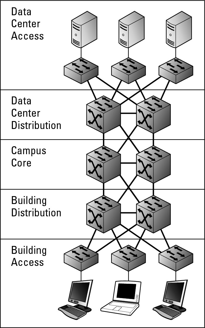
Thus far I have really been talking about user equipment being connected to the access layer and aggregated at the distribution layer. However, in large networks with dozens or hundreds of servers, you actually have two distribution and access layers: one access layer and one distribution would support the user devices, such as computers and printers; the other access layer and distribution layer would support the servers. Typically a server room (or data center) is a large room with raised floors (so all of your cabling can be managed under the floor), redundant power, air conditioning, and hundreds of servers. This room may be located in your main building, or could be housed in another building, dedicated to supporting this computer equipment.
Suggesting that your enterprise class network has many servers, Cisco uses the term data center when referring to the access and distribution layers that are to be used for your servers and server room devices. The other Cisco term that I introduce in this section is campus. In this case, campus refers to your office or internal corporate network. This may be a portion of a floor in a building, several floors of an office tower, or a private network that spans many buildings, such as a college campus; in all cases, it represents a network where you own all of the wires from the user computer through the network to your servers. Figure 2-6 illustrates these two additional layers in the network model. When working with this five layer version of network design, you can see that network core is actually in the middle of the path from the user computers and the servers.
Figure 2-6: Data center access and distribution layers.
Enterprise modules
Finally, in addition to the three layers in the network (see the previous sections in this chapter), you can include additional enterprise-level modules. The modularization of the network aids in identifying problem domains, and the enterprise modules keep these components in separate areas. I discuss the four main functional areas of your network, of which three areas will contain enterprise modules. Start with the network diagram shown in Figure 2-6, which depicts your internal corporate network. This is now labeled Enterprise Campus in Figure 2-7. It has this new name because you are now looking at the whole network from a slightly higher altitude. Figure 2-7 also shows you the three areas in which you will find the enterprise modules:
• Enterprise Campus: The main part of your network infrastructure that is directly connected to each other and where you own all of the wiring, which I discuss in the earlier section, “Access layer.” This is the entire network if you have no remote connectivity, including Internet access.
• Enterprise Edge modules: As edge suggests, this is the edge of the corporate network as it relates to the Enterprise Campus components.
• Service Provider (SP) Edge modules: Facing the Enterprise Edge is the SP Edge, representing the edge of the Service provider network.
• Remote modules: Any enterprise resources that are away from the Enterprise Campus are part of the remote modules.
The full layout of the enterprise model is shown in Figure 2-7.
Figure 2-7:
The enterprise architecture model.

Enterprise Campus
The three main network layers (core, distribution, and access) can still be identified in the Enterprise Campus, which is so named because it represents the entirety of your network’s directly connected infrastructure, where you are in ownership of all infrastructure wiring, and thereby in control of the network infrastructure. Above the campus core, I included the server distribution and access layers that I introduce in the earlier section, “Access layer.”
These are the server farm, or data center distribution and access layers. They play a similar role to the main access and distribution layers, but in this case, for traffic to and from your servers and other core network devices. The requirement for these additional layers is dependent on the number of devices that are in use in the server farm or data center.
Also connected to the core of the Enterprise Campus is the edge distribution. This distribution layer acts as the interface to all Enterprise Edge modules, which include all components that allow traffic to flow to or from the Enterprise Campus network, such as to a remote office, a remote user, or the Internet. This distribution layer acts like the other distribution layers you have seen in the “Distribution layer” and “Access layer” sections of this chapter: It aggregates data coming from the edge and remote modules as it moves to the campus core.
Enterprise Edge modules
All the components in Enterprise Edge Modules are enterprise-owned resources that connect to outside components, those that belong to other parties, such as a telephone company. All these devices connect to outside resources, such as Internet firewalls, Demilitarized Zone (DMZ) firewalls, Wide Area Network (WAN) routers, remote access servers, or virtual private network (VPN) devices.
Service Provider Edge modules
The main difference between Enterprise Edge modules and the Service Provider Edge modules is that Enterprise hardware is used in the Enterprise Edge modules, whereas with the Server Provider Edge modules, you deal with infrastructure that does not belong to Enterprise but rather is owned and operated by the service provider or telephone company. The telephone company hardware may specifically be hosted at your site, but management and ownership of the hardware is the telephone company or the third-party company. This may include any Internet access technologies, such as cable modems, Asynchronous Digital Subscriber Line (ADSL) modems, satellite links, fiber termination points, phone lines, or other hardware devices.
Remote modules
Remote modules represent any piece of the remote infrastructure that needs to use technology at the Service Provider Edge to communicate with the core network. This represents any devices that do not reside at the Enterprise Campus network location. These remote components may be remote data centers that are used as disaster recovery sites, branch offices, or remote teleworkers using any type of technologies to access data. Your BlackBerry device or smartphone represents a device that fits into this module.