This chapter discusses how to provide a high availability of systems, including network redundancy and fault tolerance. It covers protocols such as the Hot Standby Router Protocol (HSRP) , Virtual Router Redundancy Protocol (VRRP), and Gateway Load Balancing Protocol (GLBP) to increase network uptime. High availability is a requirement that companies use to keep mission-critical networks and applications available. Imagine if Amazon or Google had a four-hour outage. How much money would these companies lose because of this outage? Possibly millions of dollars. Thus, you see the importance of high availability.
High Availability
Availability Table
Availability | Downtime per Year | Downtime per Month |
|---|---|---|
99.999999% | 315.569 milliseconds | 26.297 milliseconds |
99.999990% | 3.15 seconds | 262.97 milliseconds |
99.999900% | 31.5 seconds | 2.59 seconds |
99.999000% | 5.26 minutes | 2.16 minutes |
99.990000% | 52.56 minutes | 4.32 minutes |
99.900000% | 8.76 hours | 43.8 minutes |
99.000000% | 3.65 days | 7.2 hours |
98.000000% | 7.3 days | 14.4 hours |
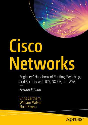
Cisco hierarchal model
You can increase availability by creating multiple links to each device, based on the level of redundancy and availability needed, and your company’s budget. This way, if one link fails, the users or services are still available. Links connecting the access layer to the distribution layer should be trunked and port channels should be configured to increase availability. Port channels and STP were discussed in Chapter 5. Recall that port channels are used to logically link multiple physical ports together to increase bandwidth and provide redundancy. Why do we use STP? STP is used to prevent loops in our networks, which increases our availability as resources are saved and should be used if you have redundant links. Trunking was discussed in Chapter 5. Chapter 6 covered routing protocols. A dynamic routing protocol should also be used to provide fast convergence when links fail.
Device reliability can be increased by using redundant devices, including core routers and switches. You limit a total outage if you have multiple core routers, including multiple connections to the Internet. You also need to remember little things such as power. Use devices that have multiple power supplies and connect the power supplies to different power sources, so if one source fails, the device does not fail. Let’s not forget about power generators as a source of power in the event of a catastrophic power loss.
Layer 3 Multipathing
Ethernet uses the Spanning Tree Protocol to shut down redundant paths and leave only a single active path from the root to remote ports. You can design for redundancy, but you can’t take advantage of all your bandwidth. This is because Ethernet does not have protections built into the frame for it to die when the frame is looped. Layer 3 protocols are designed to allow forwarding on multiple paths. When there is a routing loop, the time to live (TTL) in an IP packet will prevent it from looping past the maximum TTL.
Most routing protocols support Equal Cost Multipathing (ECMP). That means if a router sees paths that appear equal, it will split the load between each path. By default, most routing protocols will support four equal cost paths, but it can be changed. Some routing protocols also support Unequal Cost Multipathing (UCMP). These protocols will split the traffic in proportion to the metrics. BGP and EIGRP are examples of protocols with UCMP support.
In environments where full use of your bandwidth was required, the available options used to be either manually splitting the VLANs to different paths using PVST or MST or pushing layer 3 to the access layer. In modern networks, we have another solution. Virtual Extensible LANs (VXLANs) allow you to push layer 3 down to the access layer switches while maintaining scalable layer 2 domains. VXLANs encapsulate layer 2 traffic in tunnels. Layer 3 routing is used for the underlay. From the perspective of the end hosts, they are on the same broadcast domain as hosts in the same VXLAN even if they are four router hops away. VXLANs are heavily used in the data center. We cover VXLAN configuration in Chapter 19.
Even with technologies such as VXLANs that can extend a layer 2 network over a layer 3 underlay, we need to evaluate why we need the hosts on the same network. Some applications have a requirement for being in the same broadcast domain or need to be able to fail over between sites without changing their IP address. Another common reason is access control. Traditional access control is tied to a network’s layer 3 interface. Modern networks can use security group tags (SGTs). SGTs associate authenticated users or hosts to tags. The access controls are applied to the tag instead of the network. If you only needed to push layer 2 to the access layer for security reasons, you would change your design to push layer 3 to the access layer and enforce network access control with SGTs. With this design, you have the multipath advantages of routing without losing the segregation provided by VLANs.
First Hop Redundancy Protocol (FHRP)
FHRP is a group of protocols that provide redundancy by allowing a router or switch to automatically take over if another one fails. The three protocols discussed in this chapter are HSRP, VRRP, and GLBP.
HSRP
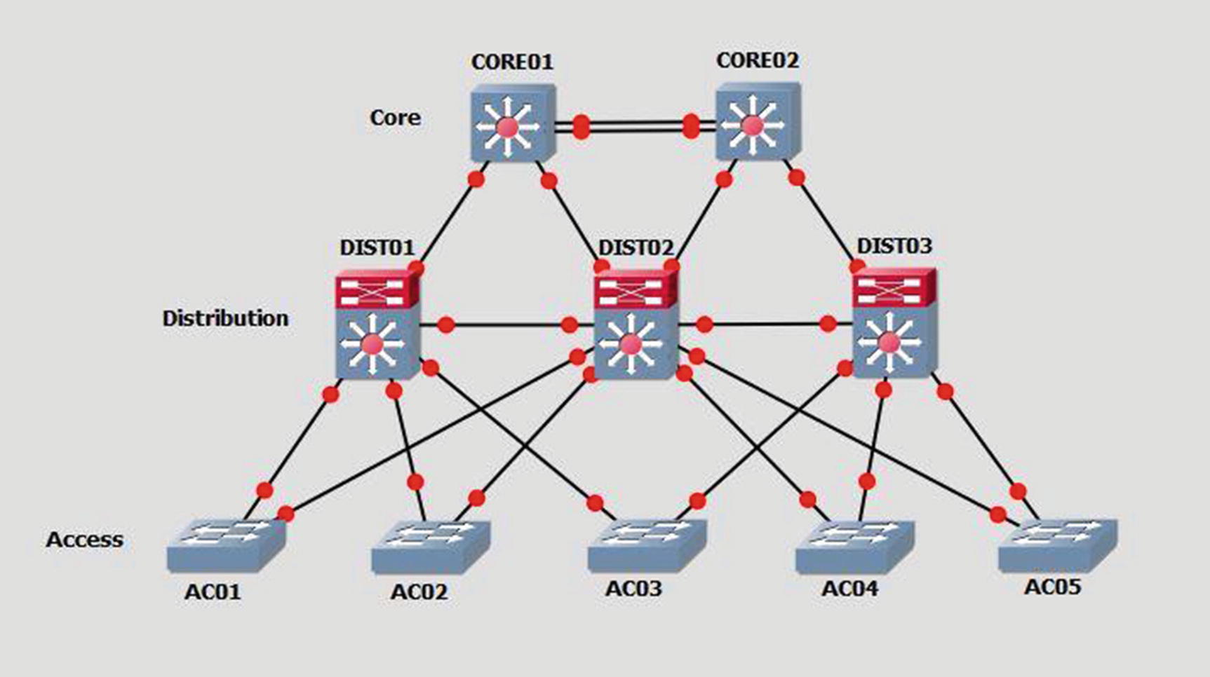
HSRP was developed by Cisco (proprietary) to solve problems dealing with router redundancy. HSRP provides automatic failover of routers. To configure HSRP, routers must share the same virtual IP and MAC addresses. The virtual IP (VIP) address is the gateway for end devices. Only one of the routers is active and receives and forwards packets. If the primary router fails, the standby router takes over the VIP and MAC addresses and receives and forwards packets. HSRPv1 uses multicast address 224.0.0.2 and HSRPv2 uses 224.0.0.102 to communicate with each router. HSRPv2 increases the number of groups available and provides a few other efficiency announcements over HSRPv1.
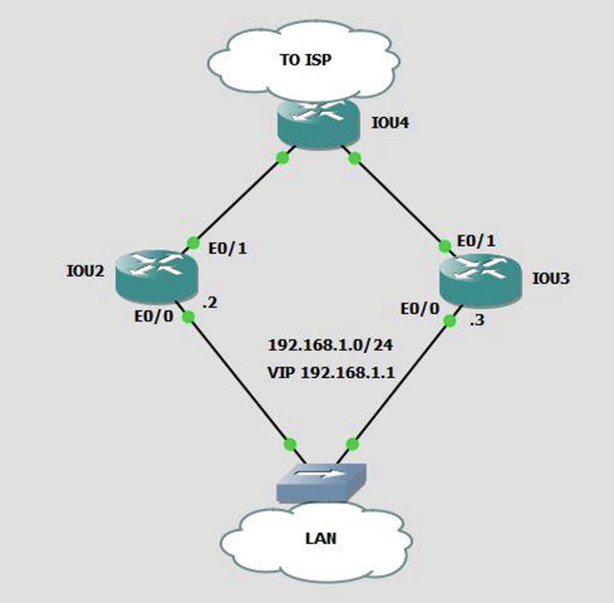
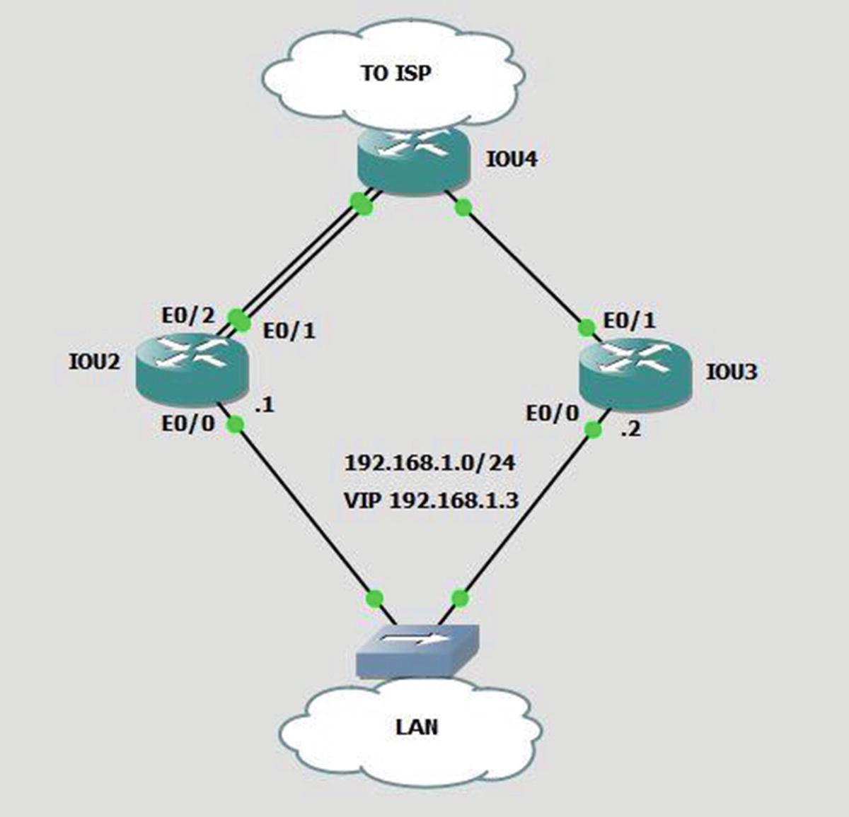
HSRP example
The standby ip command is used to configure an interface as a part of an HSRP group.
The interface IP address is on the same network as the VIP address. The standby ip command is followed by the IP address of the VIP.
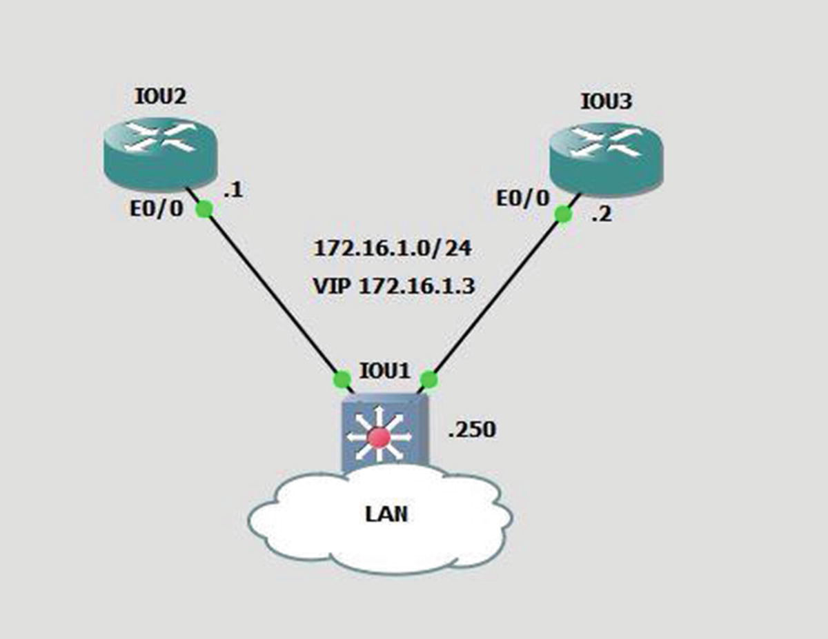
HSRP example 2
The track command is used to tell the router that if interface E0/1’s line protocol drops, then its priority will decrement by 12, which makes IOU3 the active VIP since its priority is 90 and IOU2’s becomes 88. If no decrement is entered, the default of 10 is assumed.
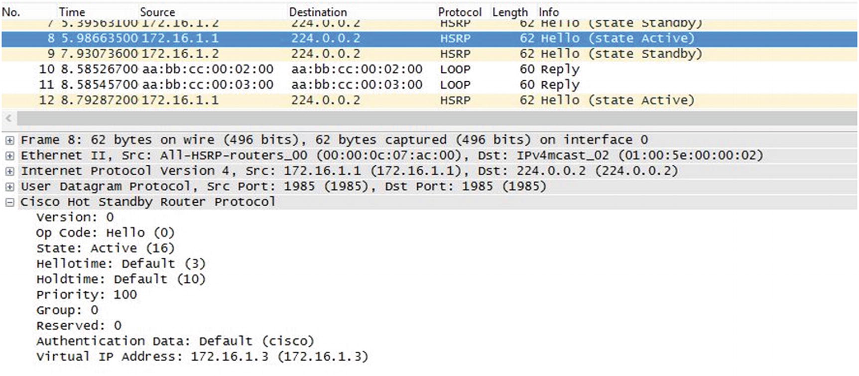
HSRP packet capture
As you can see in Figure 13-4, the HSRP packet has information such as its state, priority, group, and VIP.
Authentication can be used to increase the security of HSRP.
VRRP
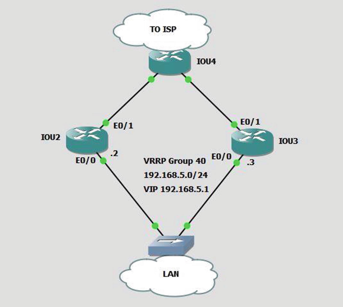
VRRP example
VRRP version 2 is being phased out. In modern versions of IOS-XE, you need to enable VRRPv2 in global configuration mode using fhrp version vrrp v3. Devices that only support VRRPv3 will not show any interface commands until it is enabled in global configuration. The configuration on the interface differs slightly from earlier versions of VRRP. Use vrrp <group number> address-family ipv4 to enter sub-configuration mode under an interface. Once in VRRP interface sub-configuration, most of the same commands apply, but remove the vrrp <group number> before the command.
GLBP
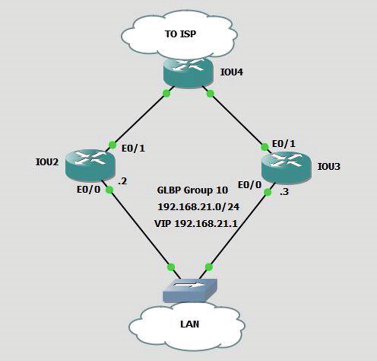
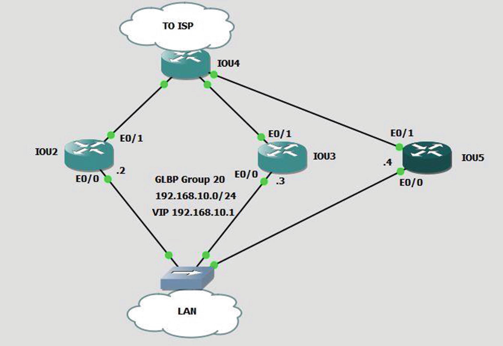
GLBP example
The GLBP 10 weighting 50 command tells the router to use 50% of the bandwidth traffic load. The default weight of 100 is not specified. If both are 50, then the MAC address of each router is sent equally.
The GLBP 10 weighting 50 lower 35 upper 40 command is the same as the previous command, except that it sets a threshold on the weight of the router. If the weight falls below 35, the router stops participating in GLBP.
Multilinks
Multilink example
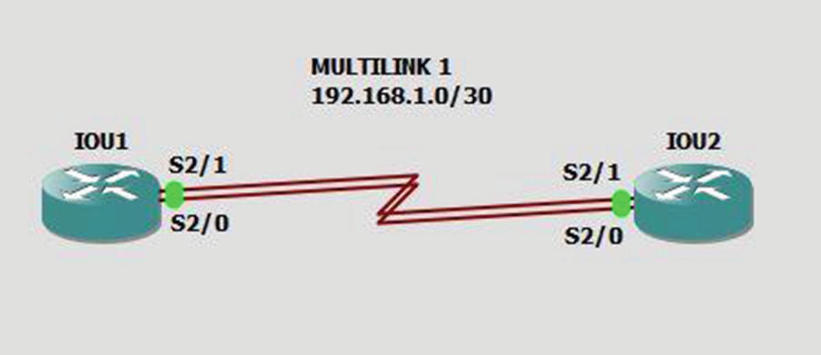
The interface multilink # command creates the logical multilink interface.
The encapsulation ppp command sets the encapsulation of the interface to PPP.
The ppp multilink command enables multilink on an interface.
The ppp multilink group # command enables an interface to join the designated multilink group interface.
You have successfully pinged the other end of the multilink and verified connectivity.
Availability Exercises
This section introduces exercises that will reinforce information covered in the chapter.
Exercise Answers
This section provides answers to the questions from the “Availability Exercises” section in this chapter.
Exercise 1
If both e0/1 and e0/2 interfaces drop on IOU2, the priority is 110 – 5 – 5 = 90. The priority of IOU3 is 103, so it becomes the active VIP. Let’s prove it by shutting down interfaces e0/1 and e0/2 on IOU2.
You can see that IOU3 has become the active router and that the priority of IOU2 has changed to 100.
Exercise 2
You have verified that IOU2 was the master router until you shut down interface e0/1 and then IOU3 became the master router.
Exercise 3
IOU5 has the same configuration parameters as IOU3.
The weighting is 30 after interface e0/1 is shut down, because it was decremented by 20. You have verified that our configuration worked properly.
Summary
This chapter talked about the importance of high availability and redundancy. Most companies consider high availability a high priority for their services. You have learned how to configure HSRP, GLBP, VRRP, and multilinks. All of these can be used to allow redundant network links, which provide high availability of resources. Remember that GLBP not only provides redundancy but also load balances between routers.