No other network security device is as common as the firewall; however, modern firewalls have evolved leaps over the traditional state tracking firewalls. Modern firewalls provide options such as traffic normalization, application inspection, intrusion detection integration, and Virtual Private Network (VPN) capabilities among many other features. The Firepower series was born from a combination of Cisco’s ASA firewalls and Sourcefire’s Intrusion Prevention System (IPS). They are powerful next-generation security appliances that go far beyond being just a firewall.
In this chapter, we cover the more commonly used Firepower features. It would take an entire book to cover every feature.
Testing Policies in a Safe Environment
The Cisco Firepower system has an extensive set of features that take time and practice to master. The dilemma is: how do we construct complex policies that can be effective without affecting production networks and gain enough real-world experience to master the technology? In order to construct complex policies, a virtual or physical test bed is needed.
Cisco offers virtual versions of their next-generation Firepower appliance and the Firepower Management Center (FMC) . When you install the Firepower system, you can enable a 90-day evaluation license. This gives you the software, but you still need an environment to run it. VMWare is a common and easy-to-use virtualization solution. You can get player versions of their software for free or 60-day evaluation copies of their enterprise option. Another virtualization option is KVM (Kernel-based Virtual Machine) . It comes free on Linux, but it takes a bit more work to set up than VMWare. If you are using EVE-NG, it is using KVM to host the images. You just need to get the images onto the server.
For the operating system component, Microsoft provides 90-day evaluation versions of their operating systems. Linux is generally free.
None of this will work if you don’t have the hardware to run it. New servers are expensive, but off-lease and refurbished servers and professional desktops can be obtained for much cheaper. Everything I have in my lab is end of life but works for lab purposes.
Once you have the hardware, you can start putting it together. In this chapter, we use Kali Linux to test attacks against our system. We use Metasploitable as a target for attacks. It is a Linux image that is vulnerable to several known exploits. We use Ubuntu with Splunk as a monitoring server. We use Windows 10 for our end hosts. We use Firepower 6.6.1 for our firewall and management system, and we use Cisco CSR1000V virtual routers on each side of the firewalls. All of this is running on VMWare ESXi.
Management Access and Configuration
The Firepower series security appliances are managed by a web front end. Most organizations centrally manage the platforms using the Firepower Management Center (FMC). If you are used to command line configuration, you may be slightly disappointed. You can see a running configuration from the Firewall appliances, but much of it is just for viewing and cannot be configured from the command line.
We are using Firepower 6.6 for our examples in this chapter. The interface was changed for this release. If you have Firepower 6.4 in production, the examples in this book will look different, but the concepts are the same.
Initial Setup
The first step is to get the software. It is assumed that you already have a Cisco account with access to download the images. When you go to the software download search on Cisco’s web page, type Firepower. You will see options for Firepower NGFW Virtual and for Firepower Management Center Virtual Appliance. You will need both.
The KVM and ESX images are only available for major versions. You need to download a major version and then patch it. For example, if you look in the 6.4.0.9 folder, you only see patches. You need to install 6.4.0 before you can install the 6.4.0.9 patch. In our case, we are starting at 6.6.1. Firepower 6.6.1 is a major enough version that we can download the virtual image. We can also download the patch from 6.6.0.
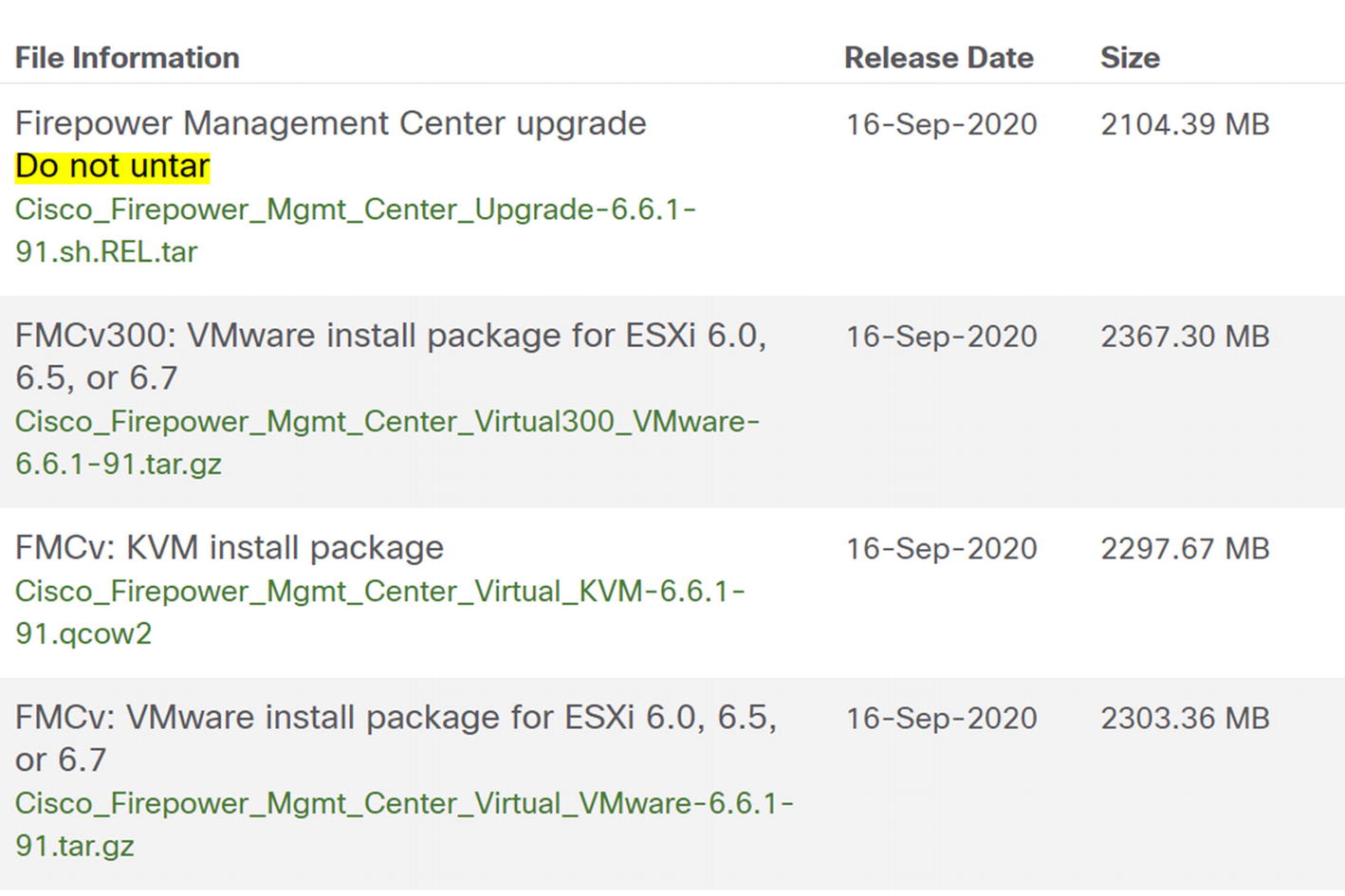
The upgrade file comes as a TAR. That is a type of Linux archive file. It is uploaded to the system as an archive. The KVM image is a QCOW2 file. It can be imported to KVM as is. The ESX image is a GZIP. You need to deflate it before using it. The VMware image has an option for VI if you have Virtual Center or ESXi if you have a standalone ESXi server. In our example, we are using Virtual Center.
Deploy the Management Console Machine
In this section, we will cover what you need to deploy the virtual machine on Virtual Center. It is assumed you are already familiar with your virtualization solution. We will focus on the Firepower-specific configuration.
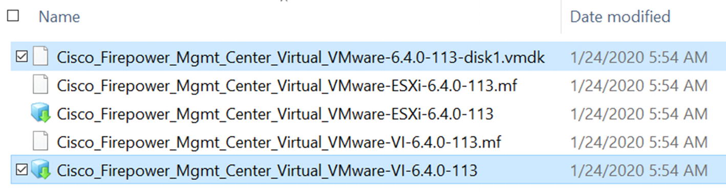
Image files for Firepower Threat Defense
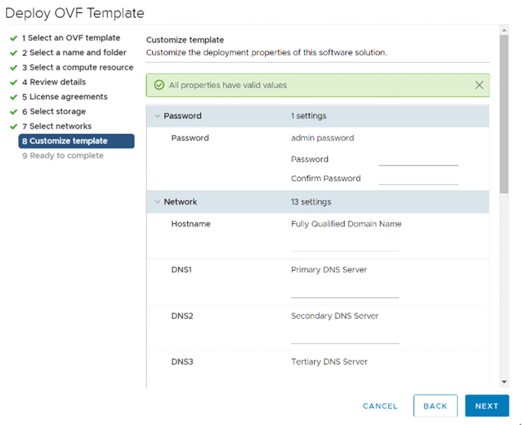
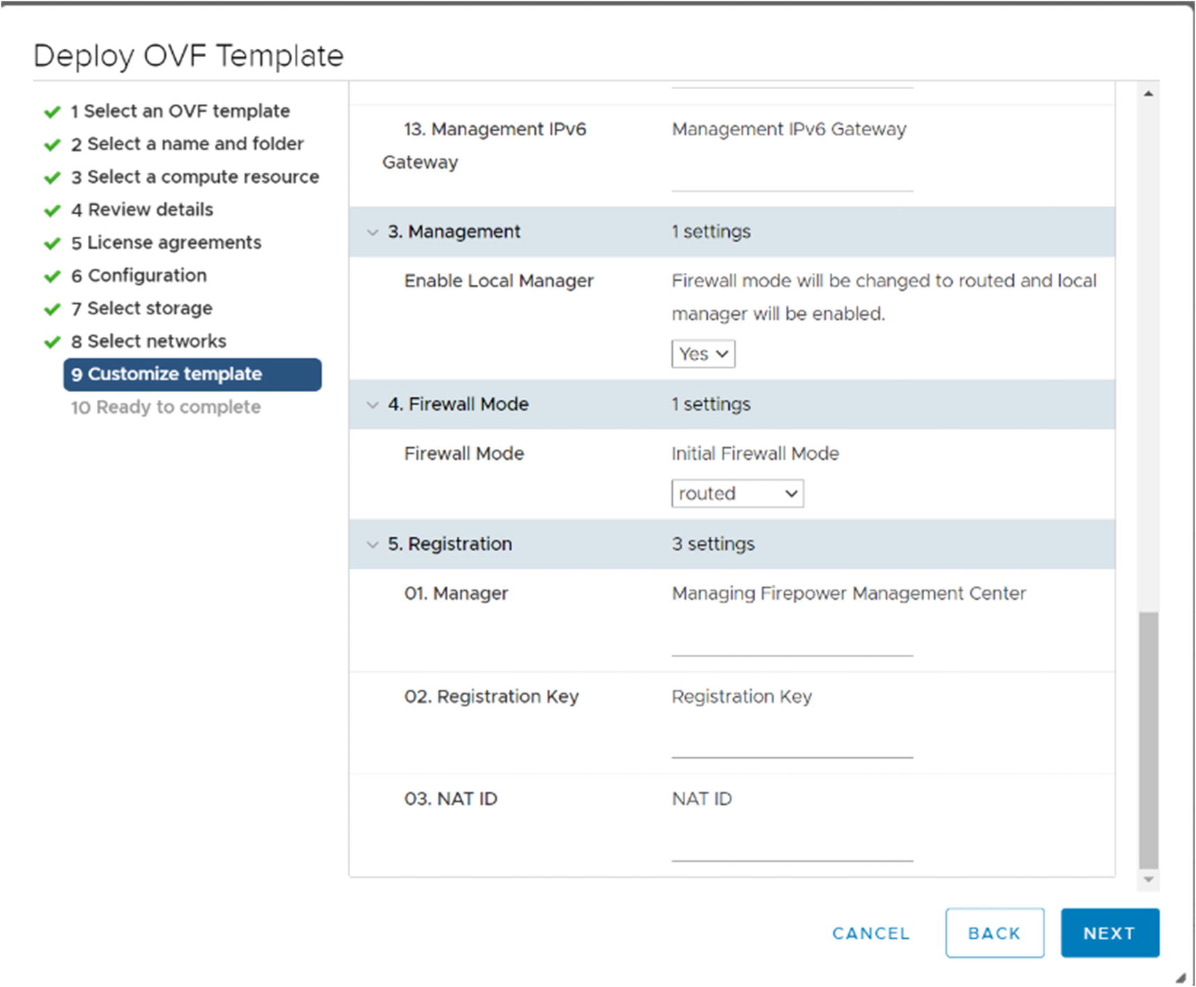
Customize template
At the Select networks step, pick the port group for your management network. In the Customize template step, enter the information for managing the FMC. Make sure not to lose the password. You will need it to log into the console.
Once you complete the OVF deployment wizard, turn on the virtual machine. It will take a while to set up. After the console has stopped showing setup messages, you can use a web browser to continue configuration.
Licensing
FMC licensing
From there, you can click an option to start your evaluation period. If you have a Smart Account, you can generate a token just like with any other device and register the FMC with Smart Licensing.

On-Prem license server
Use https://FQDN_or_hostname_of_Satellite/Transportgateway/services/DeviceRequestHandler as the URL. It will ask for a certificate . The certificate is not the certificate of the license manager. It is a special certificate. At the time of this writing, it is available at http://www.cisco.com/security/pki/certs/clrca.cer.
Deploy the Threat Defense Virtual Machines
The process for deploying the OVF for the Threat Defense virtual machines is mostly the same as with the FMC. The difference is on the Select networks and Customize template pages.

Select networks
Customize template for FTD
The Customize template page shown in Figure 21-6 has the same information as with the FMC, but it includes extra fields to allow you to configure registration to the FMC during deployment. In our example, we will manually register the device to the FMC.
Networking Requirements
Cisco recommends using SR-IOV for the network adapters used by the virtual FTD devices. Many of us do not have labs that support SR-IOV, or it is not practical to use it. If you do not use SR-IOV, you may need to allow promiscuous mode on your virtual port group for the firewall interfaces.
Stand-Alone Firepower Threat Defense Appliances
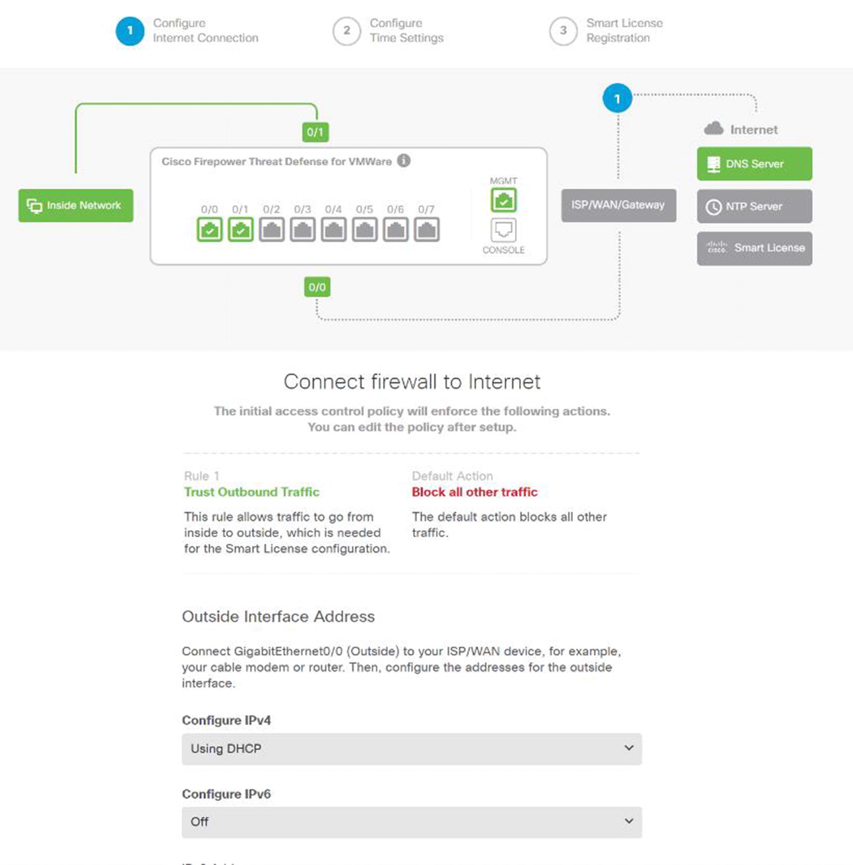
Stand-alone setup wizard
When you log into a standalone FTD for the first time, it will present you with a setup wizard as showing in Figure 21-7. The defaults are to automatically get an address from the outside interface, block unsolicited outside traffic, and allow traffic from the inside. This is like the defaults for small office and home office appliances.
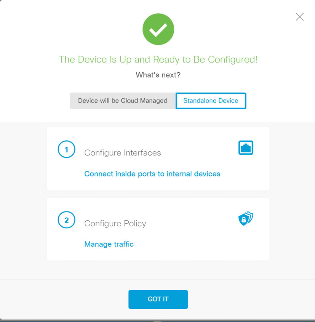
Stand-alone or CDO
If you choose stand-alone, it will suggest that you configure your policies. We will discuss policies using the FMC. In the FMC and FTD version 6.6, the capabilities are similar. In older versions, the stand-alone version is more limited.
Adding Devices to the FMC
The first step in adding devices to the FMC is to allow the FTD to talk to it. If you did this when you deployed the virtual machine, you don’t need to do it again. If you are using an FTD 4000 or 9000 series, you may have done it when creating the container. We will discuss containers later.

Configure FTD for FMC management
Use the line configure manager add <manager IP> <key> to allow an FTD device to be managed by the FMC. The key is a registration key. It is always best practice to use complex keys, but it will only be used for initial registration. We are using “cisco” as the key for simplicity.
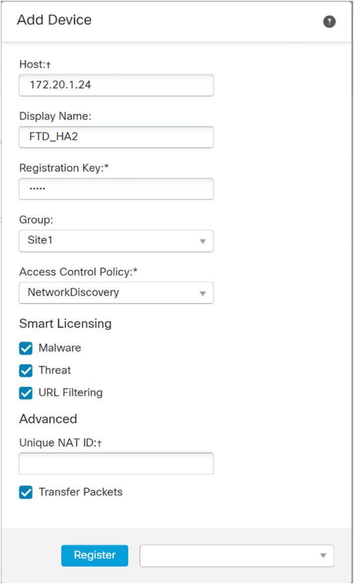
Register a device
Provide the IP address or hostname of the FTD device. Use the registration key you configured on the FTD. Select the licenses you will use. For demonstration purposes, we are using all licenses for this device. You must configure an access control policy here. In this example, I created a blank policy for network discovery. We will cover this in the “Access Policies” section. After entering all the information, click Register and wait for it to complete.
Updating and Patching
Before going operational, you should patch the FMC and managed FTDs using the recommended release.
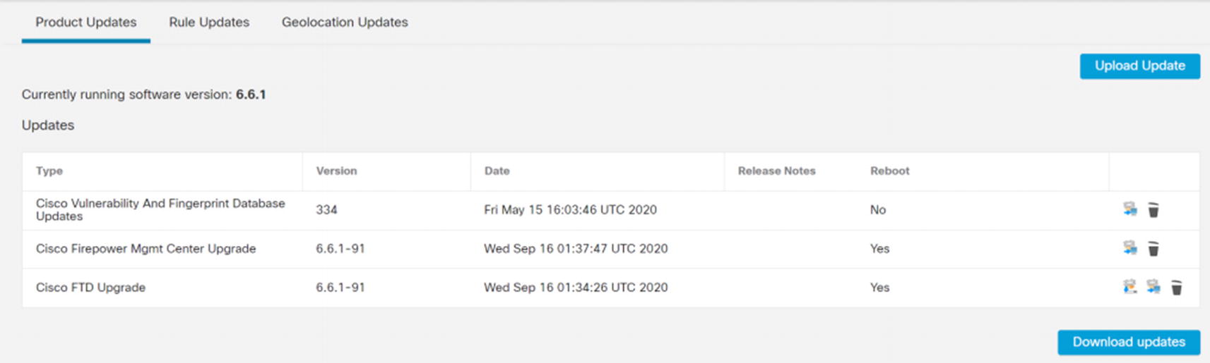
Product Updates
You have a choice of uploading updates from your local computer or downloading updates from Cisco. When you download from Cisco, you will get patches, but not major version changes. If you upload updates, you will upload the updated TAR file you downloaded from Cisco.
Once the files are on the FMC, you can click the button to install them on the platforms. It is best practice to update the FMC first and then update the managed FTDs. Upgrades will cause the systems to reboot. During initial configuration, it isn’t a problem to reboot firewalls. In production, you should have high availability configured.
Rule and Geolocation Updates and Scheduling
Product Updates cause reboots. Most administrators will only update products during outage windows, and they will watch the system to make sure everything comes up correctly. Rule and Geolocation Updates are less risky and are often scheduled.
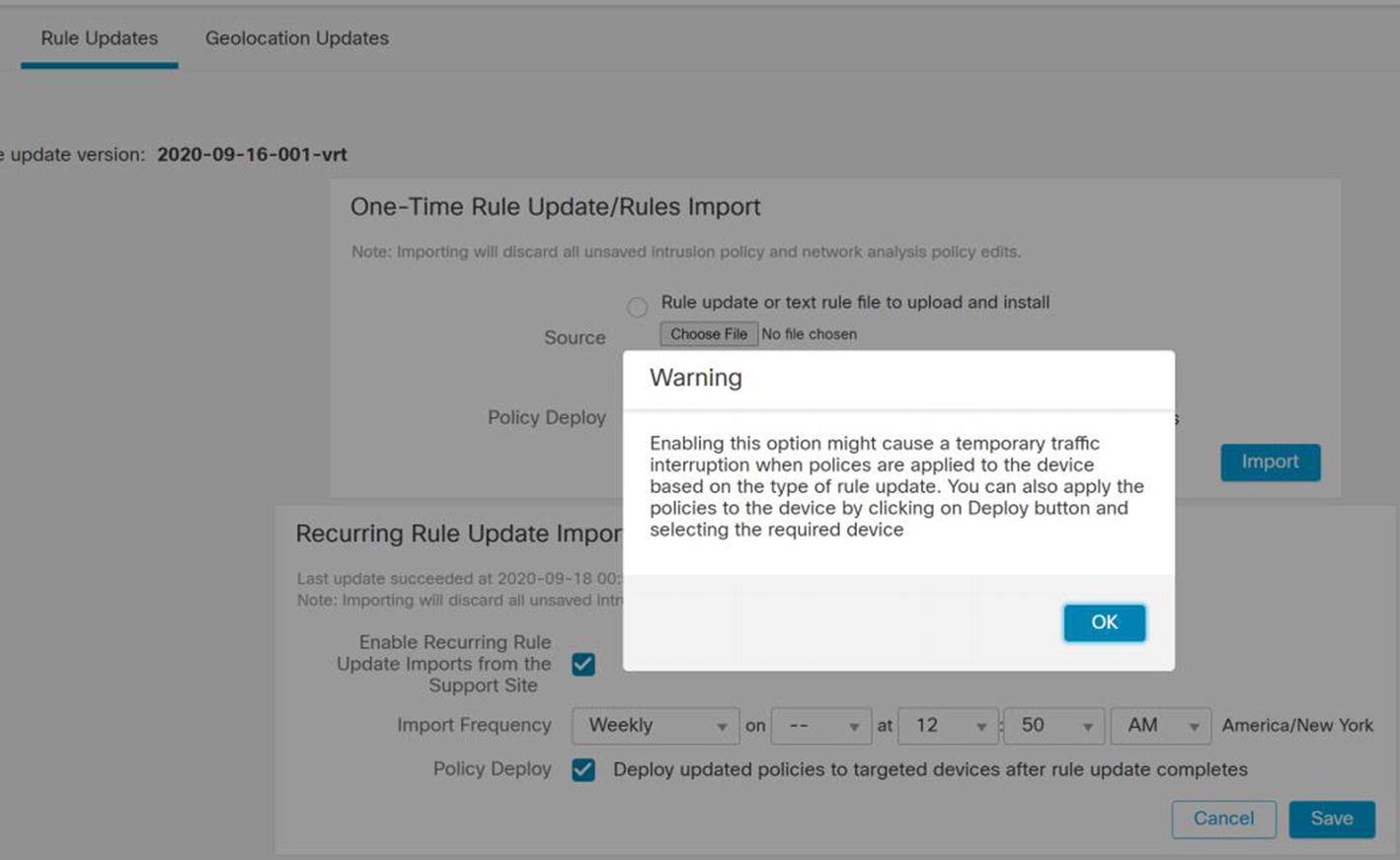
Rule Updates
Geolocation Updates do not have the same issue as intrusion signatures. They can be safely installed using automatic updates.
Objects Overview
The Firepower system has several types of objects. In most cases, we will discuss them in the context of the configuration task. At a minimum, we need to introduce the concept of objects before we continue.
An object is something you define for later use. Policies reference objects. You can change the value of objects, and the policies will inherit the change. Just because you have an object defined does not mean that it is used anywhere.
In most deployments, you will not touch a large proportion of the available object types. We will limit our discussion to providing an overview of the most common objects.
To look at the available object types, browse to Objects ➤ Object Management.
Access List
The access lists in this section are not used in the access control policies. Even though there are other uses, the most common place to use access lists is with VPN configurations. The access list is used with posturing redirection.
We will not be covering access list objects further in this book. They are only mentioned so we can clarify that they are not the same as access lists used in access control policies.
Address Pools
Address pools are commonly used with remote access VPNs. We will revisit this in the “Virtual Private Networks” section.
DNS Server Group
A common use of DNS Server Group objects is to configure DNS to VPN users.
FlexConfig
We have a brief section on FlexConfig later in this chapter. Firepower is the combination of ASA and Sourcefire IPS. The interface is based on Sourcefire’s Defense Center. Not all ASA configuration is integrated into the interface yet. FlexConfig is a workaround. It allows you to push ASA configuration to the FTDs for options that aren’t supported in the graphical interface.
Interface
Firepower is a zone-based system. The interfaces defined under Object Management are zones. When we configure our devices, we add the device interfaces to zones. If a zone hasn’t been pre-created, we can create it when setting up a device.
FMC is designed as a distributed system. You can have interfaces from more than one device in the same zone, and then you can configure access rules based on the zone.
Network
The network objects are the heart of access control policies and a few other policies. Networks can be defined as hosts, ranges, or FQDNs. The networks can be organized in groups, and the groups can be nested. Even though you can create network objects on the fly when editing policies, it is best practice to pre-stage network object groups.
PKI
PKI, or Public Key Infrastructure , contains information about certificate authorities that you can trust and information about certificate enrollment. Configuring certificates in this section does not mean they are used anywhere. PKI configuration on Firepower is slightly different than what you have encountered on other systems. It is a common source of confusion.
We cover PKI in more depth in the “Virtual Private Networks” section.
Port
Port objects define ranges and groups of ports that you use in access control policies. Port objects are not necessarily ports. The objects can include protocols other than TCP or UDP. A limitation of port groups is that they cannot be nested. That means you can’t have a port group inside another port group. When migrating from ASAs that use nested port groups, the groups must be flattened. The Firepower Migration Tool can do this for you, but you are at the mercy of how it names the groups.
RADIUS Server Group
This object defines RADIUS servers that will be used with VPN and similar configurations. This object is not used when the FMC itself uses RADIUS for administrative authentication.
URL
URL objects are used when filtering by URL. We will cover this briefly in the “Access Policies” section.
Variable Set
Variable sets are primarily used to supply variables to intrusion detection rules.
VPN
Most reusable VPN settings are configured under this object. When we configure VPNs later in the chapter, we will define these objects and then reference them in the VPN configuration.
Device Configuration Overview
After adding an FTD device to the FMC, you need to provide the configuration. By default, the interfaces on a new FTD device will be disabled and not configured.
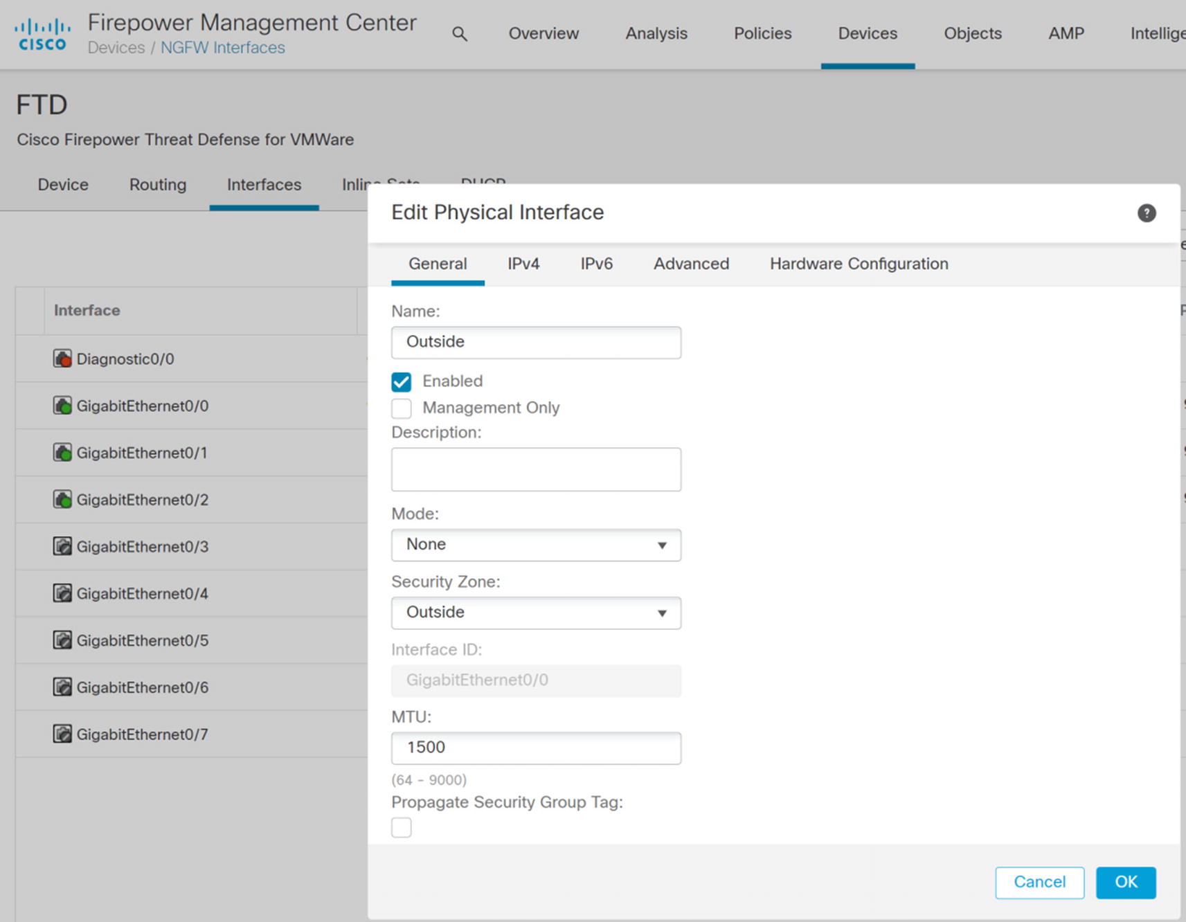
Interface zone configuration
Notice the Propagate Security Group Tag checkbox. We will loop back to that later.
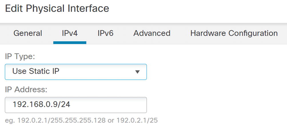
IPv4 configuration
The Advanced tab allows you to add some security controls.
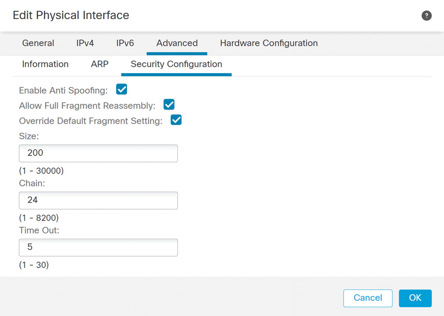
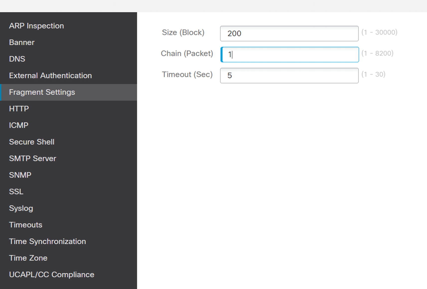
Anti-spoofing and fragmentation
Field | Meaning |
|---|---|
Size | Interface IP reassembly queue size. |
Chain length | Max number of IP fragments per fragmented transport PDU. |
Timeout | Time to wait for the fragment reassembly. |
To disable fragmentation for an interface, set the maximum chain size to 1. If that isn’t practical at your organization, it is best practice to configure your network to minimize fragmentation as much as possible.
High Availability
High availability is important for minimizing outages. The primary type of high availability supported on Firepower is active/passive failover. It is not much different than with the legacy ASA firewalls.
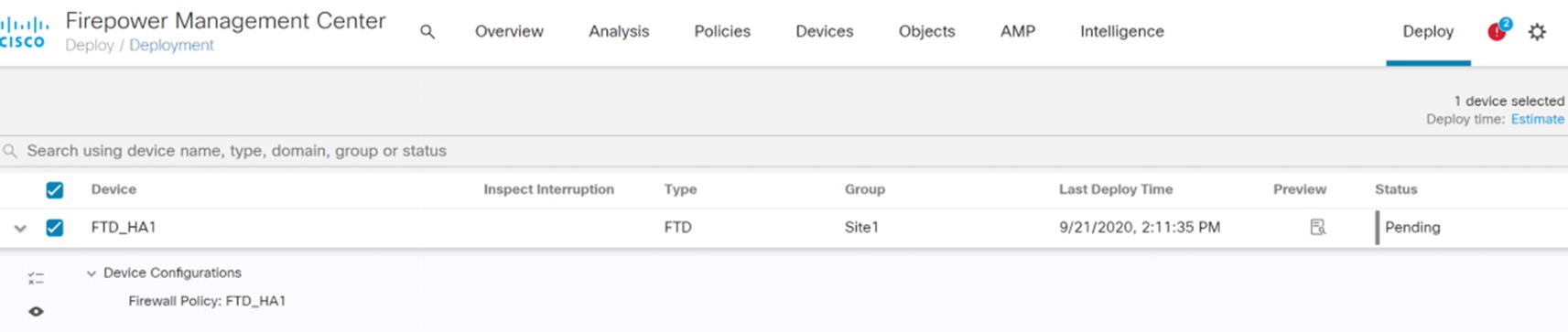
Deploy changes to FTD
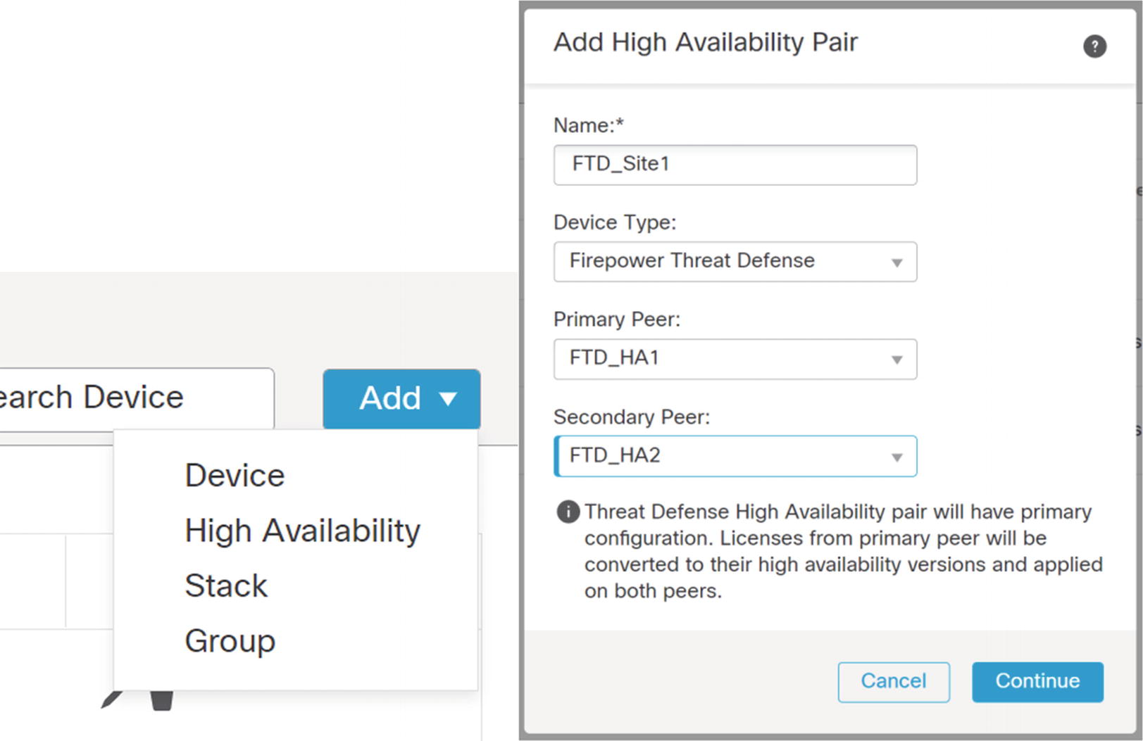
Add ➤ High Availability
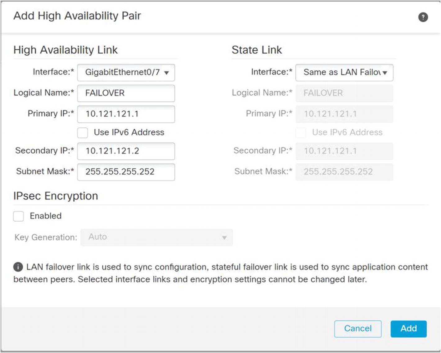
Configure failover links
Configure the links for failover. In my example, I am using a single link for both failover and state. Pick IP addresses that are not used elsewhere in your network. These don’t need to be routable because they are only on the link between the appliances. For additional security, you can enable IPsec on the links.
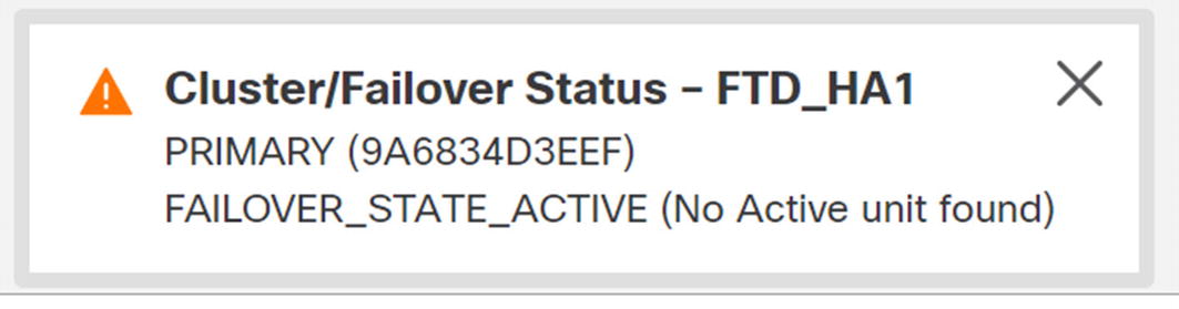
Failover state

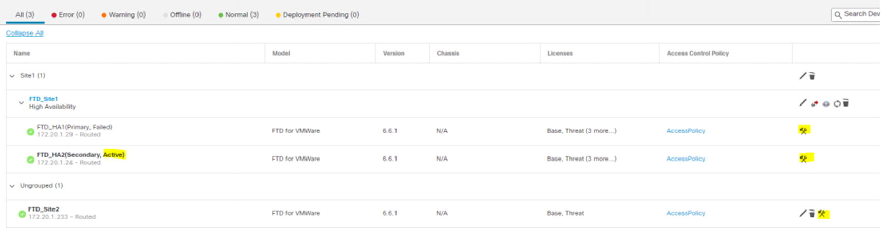
HA pair created
Troubleshooting is slightly different. Troubleshooting is still individual to the firewall. Troubleshooting is almost always done on the active appliance. In our example, the primary appliance is active. If there is a failover event, then the secondary appliance will be active. You need to pay attention to which one is active before troubleshooting. To get into the troubleshooting menu, click the tool icon for the active appliance.
Containers
The Firepower 4100 and 9300 series appliances support containers. The result is like multiple context in ASAs, even though the implementation is different. A container allows you to have multiple distinct firewall application images running. They don’t need to be the same version. They are completely isolated images that are allocated physical resources on the appliance.
Containers can be used for active/active failover in the same way as multi-context failover on the ASA. One physical appliance will host the active firewall for some instances, and the other will host the active firewall for other instances.
Lower-end appliances and the virtual appliances do not support this feature. For the virtual firewall, you can leverage your virtualization infrastructure to achieve a similar result. In that case, you will deploy multiple instances of the Threat Defense image and balance the load using tools available in VCenter.
Clustering
Clustering makes multiple appliances appear as a single appliance. This option is only available on the Firepower 4100 and 9300 series appliances. If you have a requirement for true active/active forwarding within a single logical firewall, this is a good option.
Clustering allows you to create a spanned port channel that appears as if it came from a single device. The devices on each side of the cluster will think that they are connected to a single appliance.
Routing
Firepower supports static routing, OSPFv2, OSPFv3, RIP, and BGP. Multicast routing is under the routing menu, but it is out of the scope of this book.
Did you notice that we didn’t list EIGRP? The current version of Firepower does not allow EIGRP configuration from the Routing tab. It requires FlexConfig to push ASA configuration onto the appliances.
The concepts for routing protocols are the same as with routers, with a few limitations.
Static
Static routing is common on firewalls. In many implementations, you have a default route pointing to the outside interface and a summarized route for your internal networks.
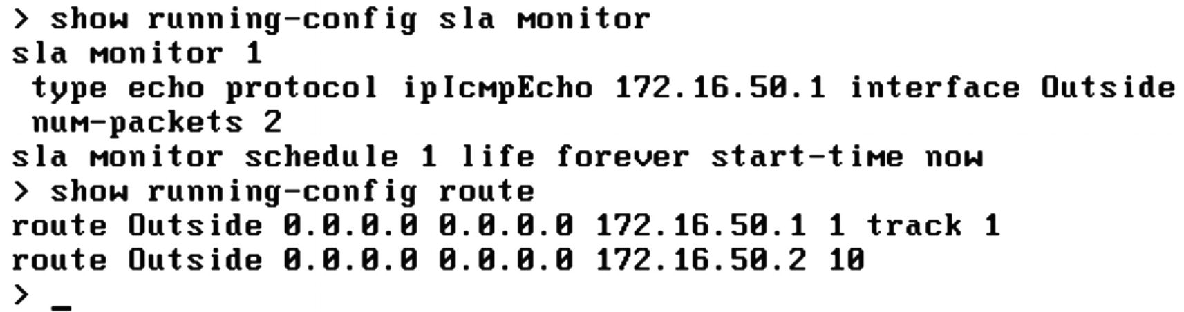
If you have more than one path leaving the network, you may need multiple default routes with different metrics. Tracking can be used to determine if the primary path is degraded.
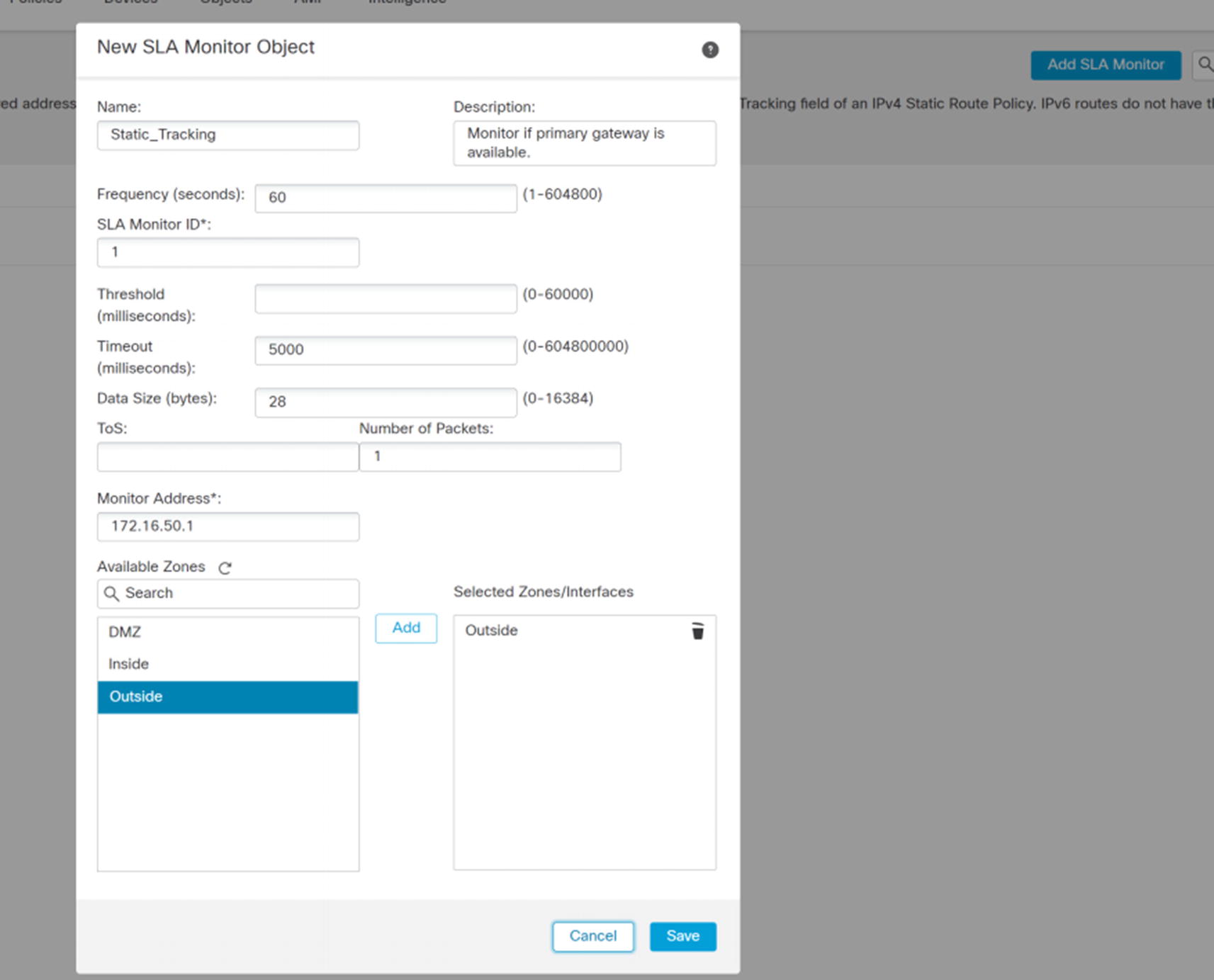
New SLA monitor object
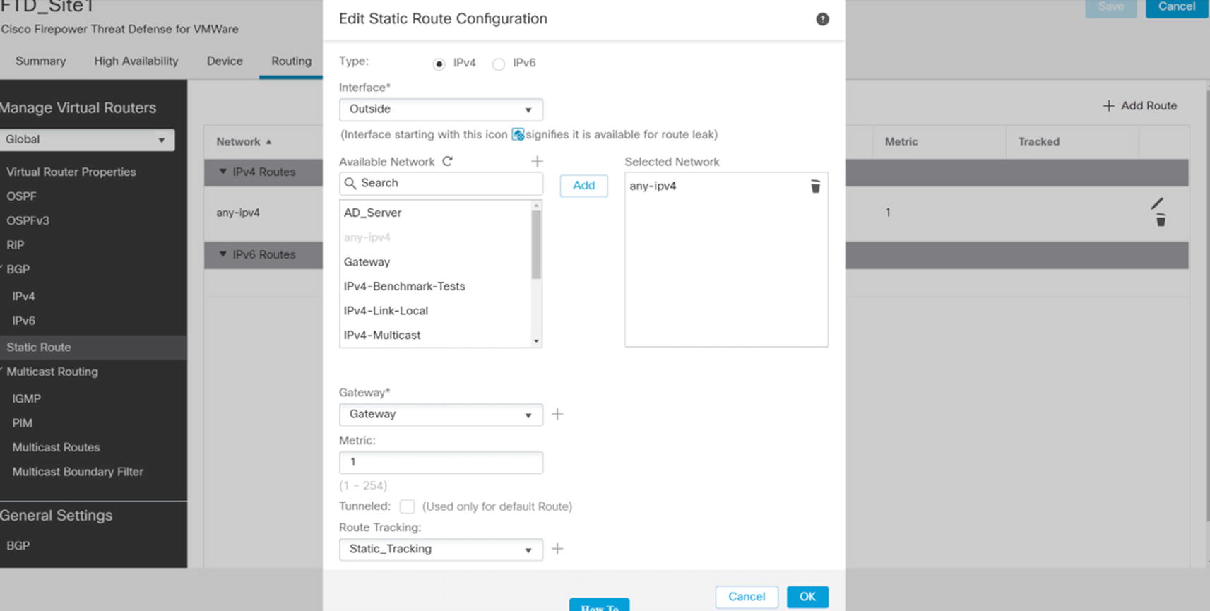
Static route
Pick the interface for the route. We named our interfaces Inside, Outside, and DMZ. Yours may differ. Select the networks that should be routed. We are creating a default route, so we selected any-ipv4. If you need to route specific networks, you need to create a network object. You can create one inline by using the plus button by Available Network. This allows you to create a network object. If you need to use a group on network objects, you should pre-create it under Object Management.
The gateway points to a host network object. We used the plus button to create a host network object containing the IP address of the next hop router.
Route tracking is optional. We are using the tracking object that we just created. When the tracking object shows that pings fail, it will remove the route. If we create a second static route with a less preferred (higher) metric, it will be used when the track fails.
Routing Configuration

Routing table

Timeout in the SLA object
Once we fix the issue, we see routing to the primary gateway.
OSPF
The FMC supports two OSPF processes. Each process maintains its own topology table. If you want to share routes between processes, you need to redistribute.
When you set up a process, you need to pick Internal Router, ABR, ASBR, or ABR & ASBR. The selection limits what you can configure. The process needs to be an ABR to allow multiple areas. It needs to be an ASBR to allow redistribution.
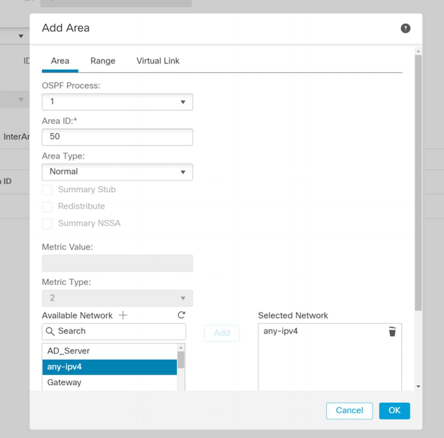
Add Area
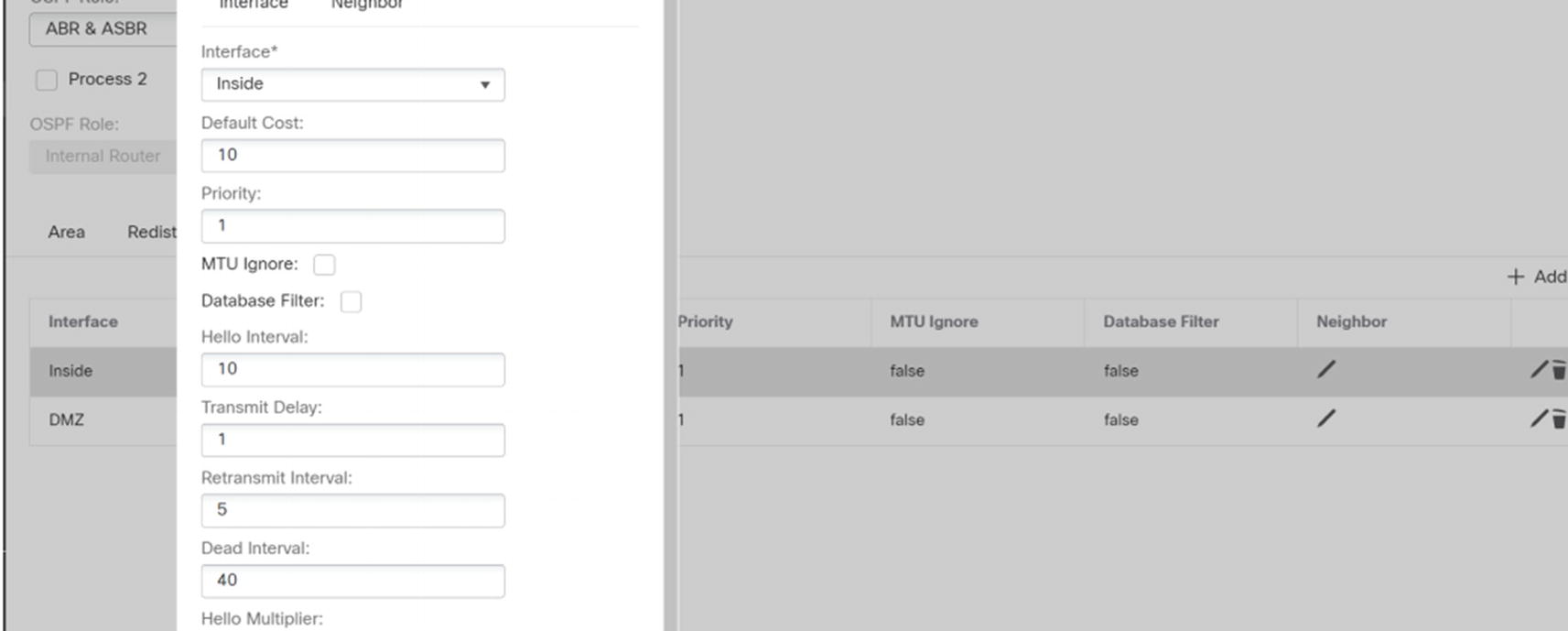
Add interface to OSPF
If required, you can change hello times, configure authentication passwords or key chains, and configure unicast neighbors from this window.

Redistribution in OSPF
Once you are done with routing, deploy your changes to the appliances.
BGP
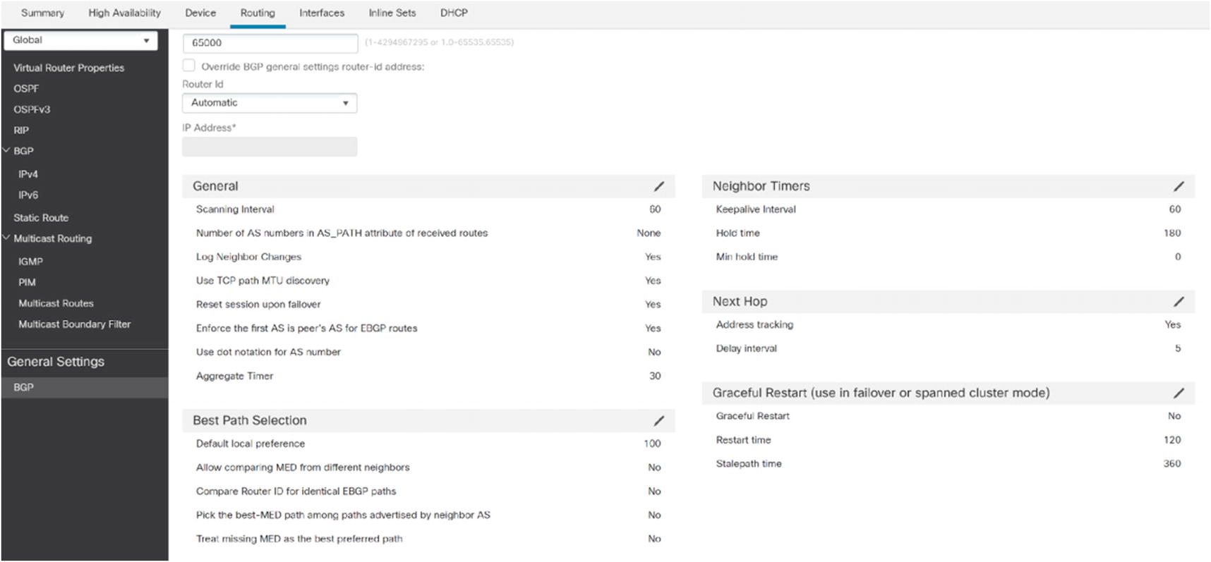
BGP General Settings
After enabling the process, you can add networks to the address family. Select IPv4 under BGP, and then go to the Networks tab. Click the Add button. As we see in Figure 21-30, you are prompted to select a network object. When you add a network in BGP, it needs to have an exact match in the routing table for it to advertise it. If BGP is not advertising any network, verify that the advertised networks match exactly with what is in the routing table. Using the command line to show route is the easiest way to see the routing table.
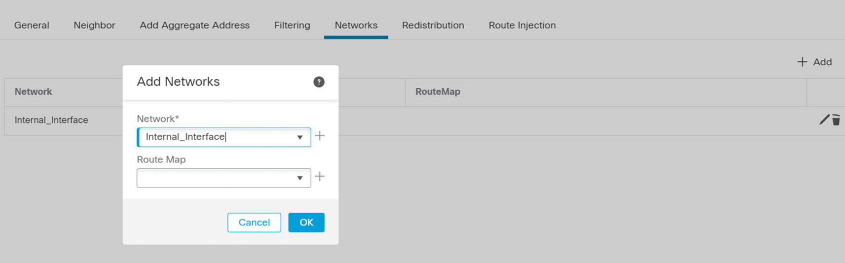
Add network to BGP
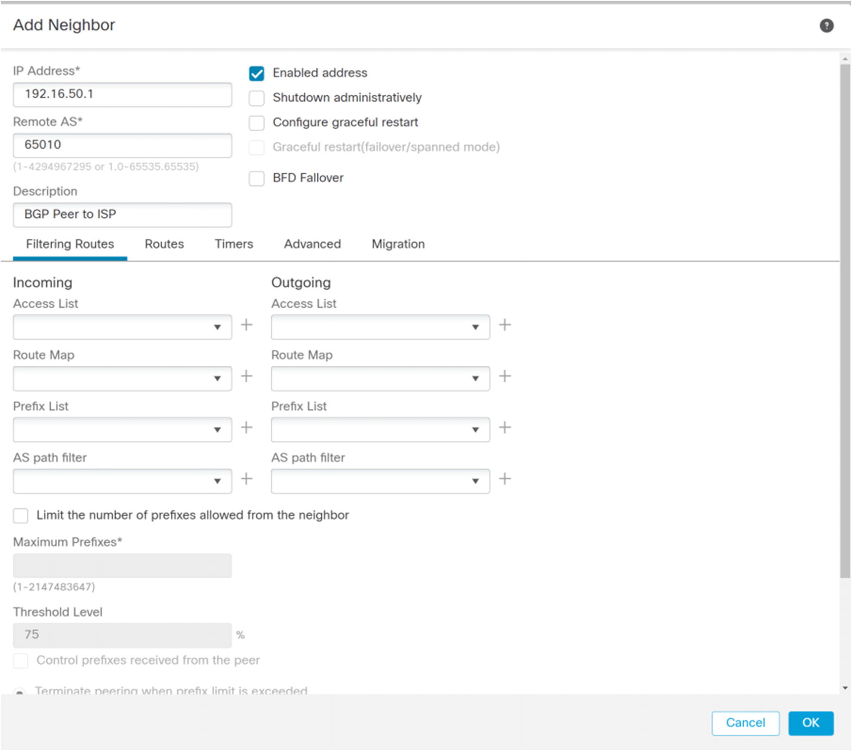
BGP Add Neighbor
DHCP Server
In an enterprise network, address assignment is usually the role of a dedicated server. However, the Firepower firewalls can act as a DHCP server or a proxy for a DHCP server.
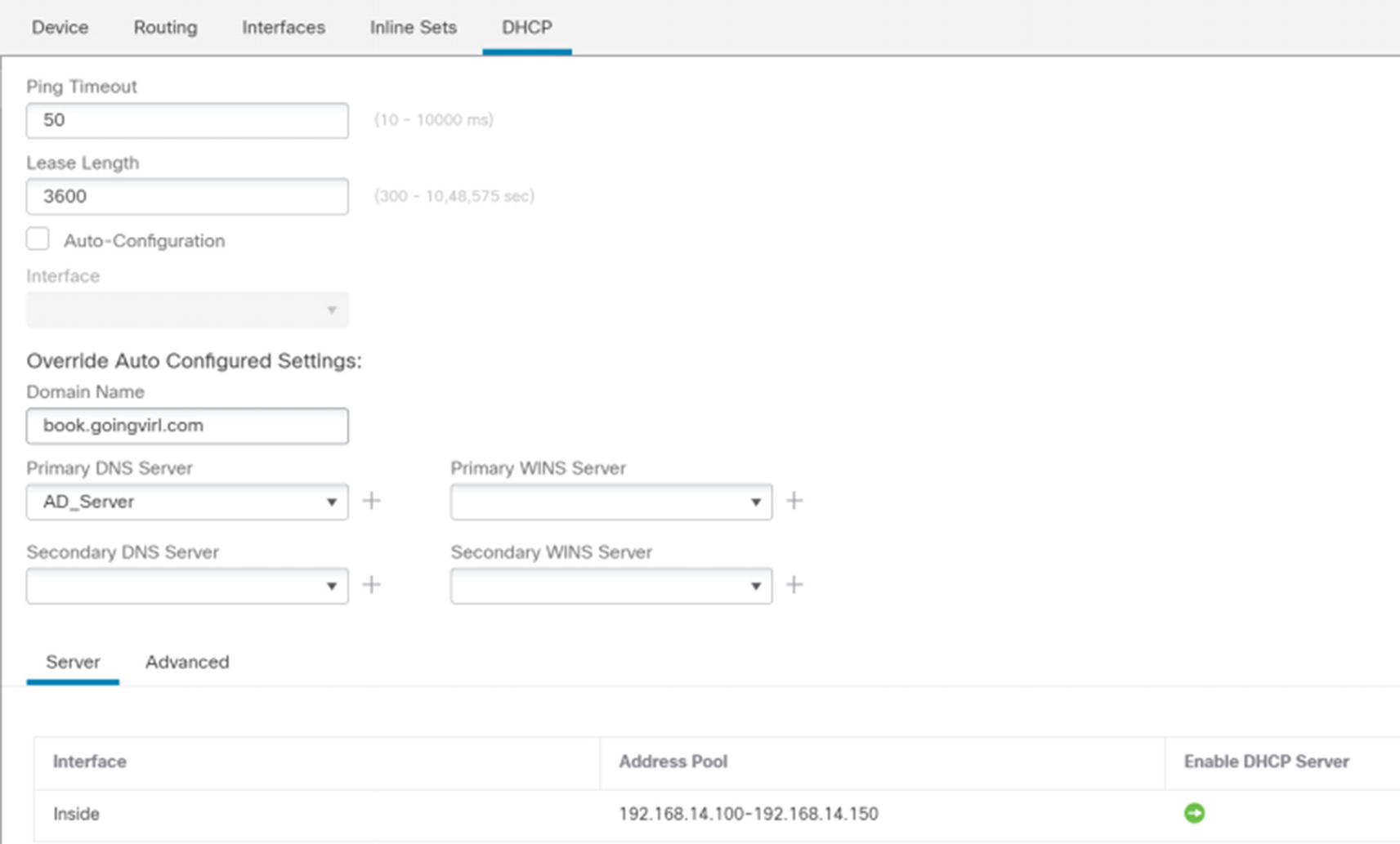
DHCP server
You can automatically obtain options for domain suffix, DNS, and WIN; or you can manually configure them. In the Server section, add a pool of addresses by using the Add button. If you need additional options, click the Advanced tab. This may be needed for VoIP phones that require Option 150 to find their TFTP server.

DHCP Relay
Network Address Translation
Network Address Translation (NAT) is used to translate addresses between interfaces. In most cases, you use RFC 1918 addresses on the inside of your network and public addresses on your external interfaces. NAT can be used to hide your inside addresses or to map many inside addresses to a single public IP address or a small pool of public IP addresses.
In the examples in this book, we use RFC 1918 addresses on both sides of the firewall. Since it is a lab environment, we are not assigning any public addresses.
NAT on firewalls uses the same principle as NAT on routers, but the configuration is different. This leads to a few caveats when setting up NAT on a firewall.

New NAT policy
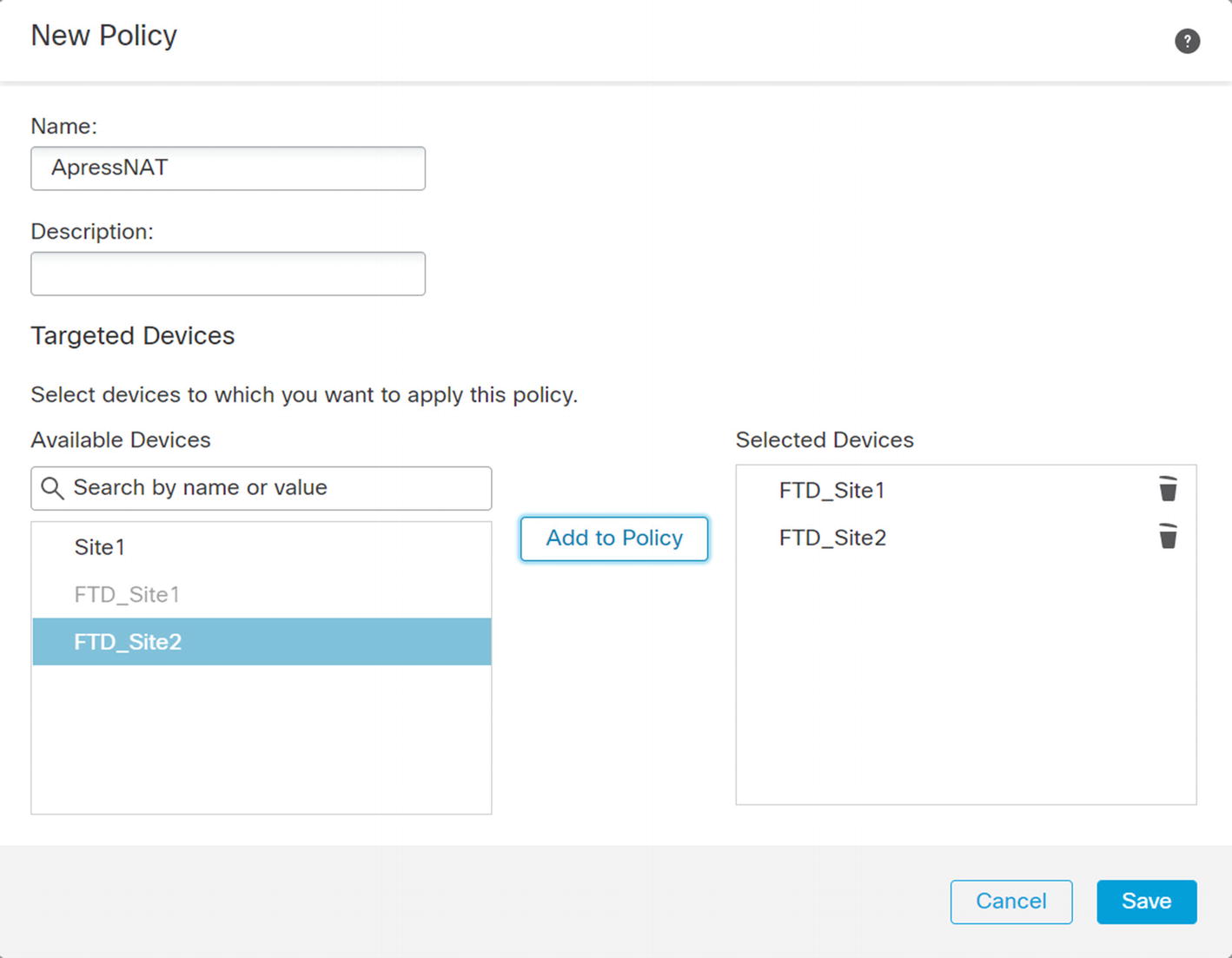
New Policy wizard
Once you get into the policy, you see three sections: NAT Rules Before, Auto NAT Rules, and NAT Rules After. This concept came from the ASA firewalls. Auto NAT has fewer options to configure than manual NAT. It is only concerned with the source. If you do not need destination information in a rule, it is recommended that you use auto NAT. In ASA firewalls, manual NAT rules are processed before auto NAT unless you added a token to tell the system to look at the rule after auto NAT. That is the source of “Before” and “After.”
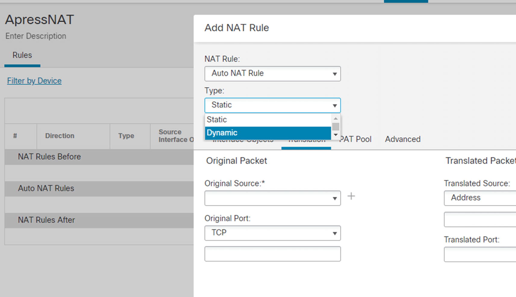
Types of NAT
Many people equate dynamic NAT to Port Address Translation (PAT). They are commonly used together, but you can use each without the other. If you have a pool of public addresses, the system can dynamically issue them without need of PAT. PAT is needed when you don’t have enough addresses in your outside pool and the system needs to translate port numbers so it can reuse IP addresses. Similarly, you can statically change a port number. In some cases, the port a server listens to is not what outside users see.
Network Description | Network ID |
|---|---|
Site 1 Outside | 172.16.50.0/24 |
Site 1 Inside | 192.168.14.0/24 |
Site 1 DMZ | 192.168.41.0/24 |
Site 1 Remote Access VPN | 10.150.150.0/24 |
Site 2 Outside | 172.16.60.0/24 |
Site 2 Inside | 192.168.13.0/24 |
We pre-created most of the network objects. You can create them on the fly or create them through Objects ➤ Object Management ➤ Network. In some of our examples, we are using network groups that must be created under Object Management.
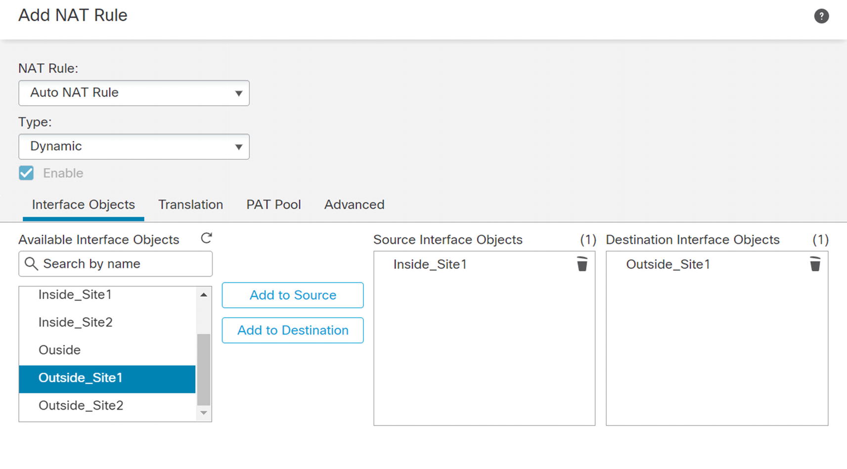
NAT rule select interfaces
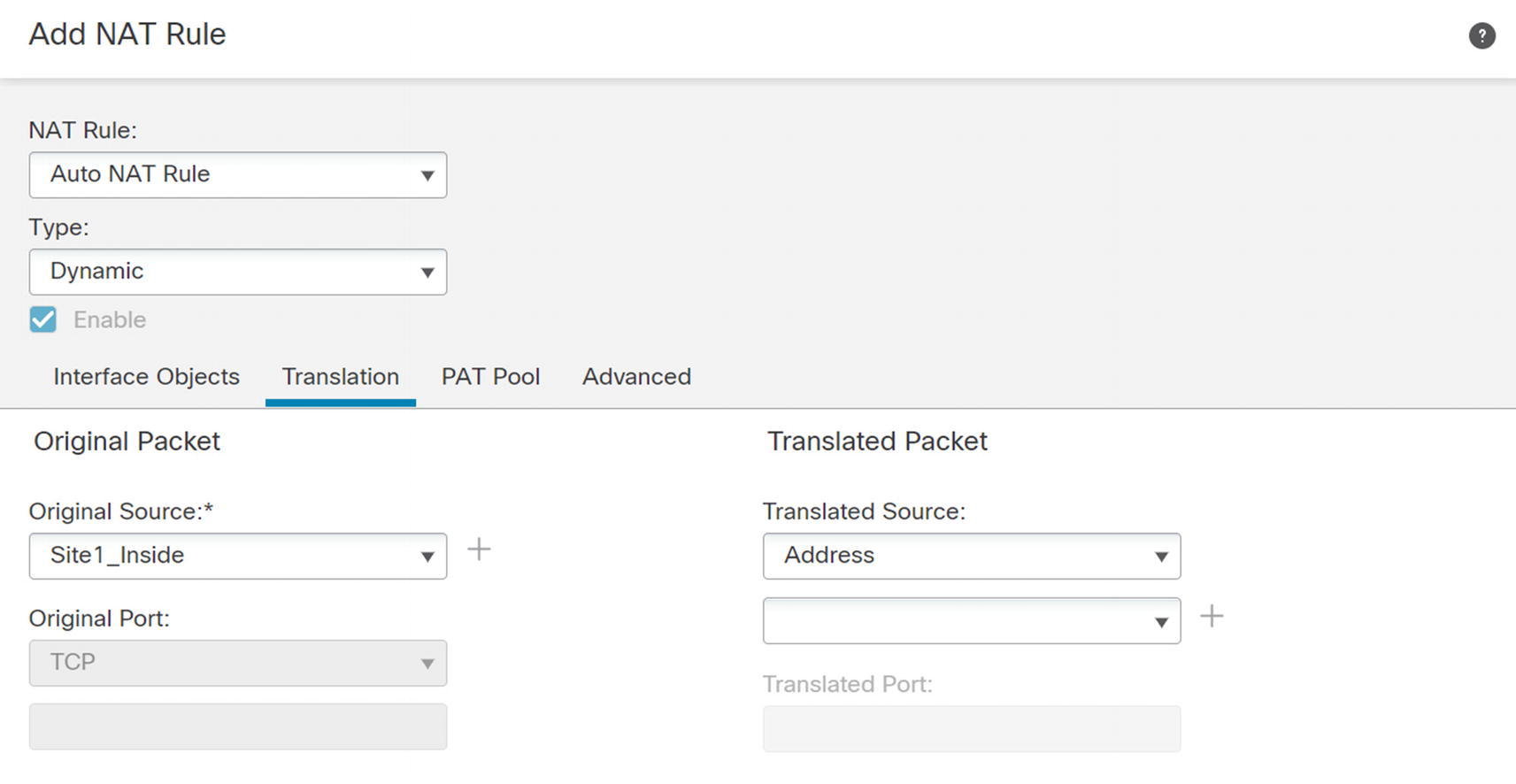
NAT source
In the PAT Pool tab, check the Enable PAT Pool box. Select Address in the dropdown. Click the plus next to the address to create a network object. Configure a range of IPs to use in the PAT pool . After creating the PAT pool, select the object in the dropdown and save. Ensure you have a large enough PAT pool to support your network. If you have too many connections tranlating to too few outside addresses, you can exhaust your PAT pool. This happens when PAT uses every port on every external address.

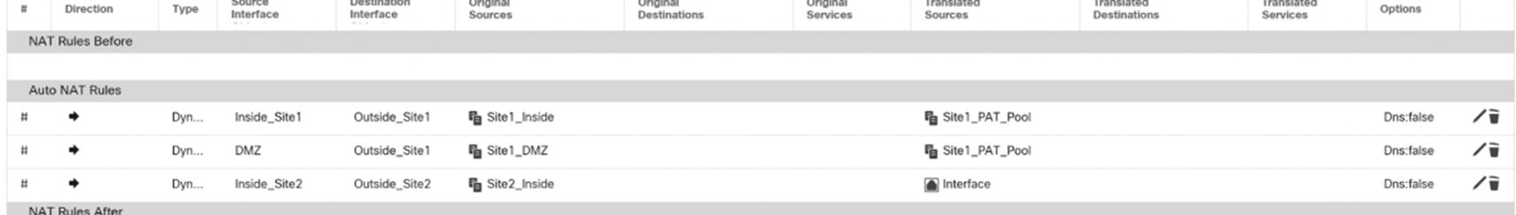
Dynamic rules
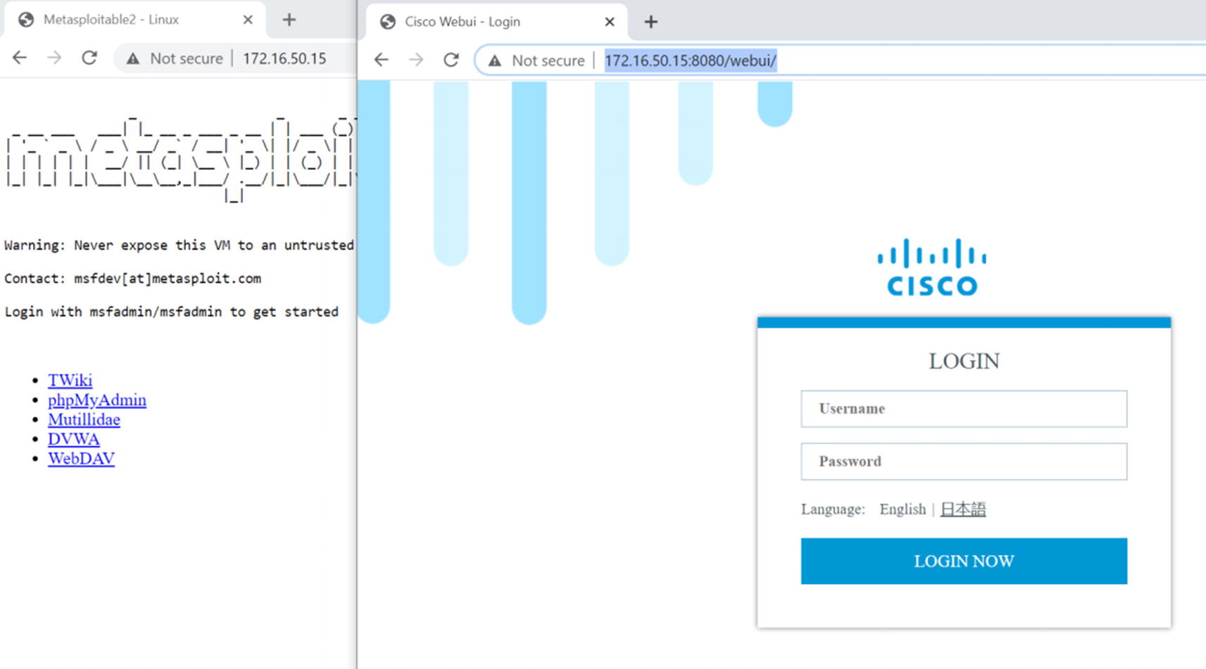
Dynamic rules will provide network connectivity for devices, but we also need some static rules for servers in the DMZ. In our example, we have two servers in the DMZ. We want the server at IP address 192.168.41.15 to appear as 172.16.50.15 to the outside, except we want TCP/80 on 192.168.41.16 to appear as TCP/8080 on 172.16.50.15. We will create the specific rule that changes ports first.

Static NAT with port translation
In our example, we used the host network object DMZ_Router as the original source and the host network object called DMZ_Outside for the translated source. We translated packets from HTTP to HTTP_Alt. By default, NAT is two way. If you need to make it unidirectional, you can check the Unidirectional box under Advanced. In our case, we want it to be two way.
The second rule is similar to the first except we used the network object Metasploitable as the source. We still used DMZ_Outside as the translated source. We left all other fields in the Translation tab blank.
We will walk through setting up a couple Virtual Private Networks (VPNs) later in this chapter. It is best practice to use a separate firewall to terminate your VPNs as your filtering firewall that has NAT. It causes risk and complexity to put everything on one appliance. One of the complications is with NAT. NAT sees the VPN traffic as coming from the Outside zone. We need to add exceptions to the policy so the VPN traffic doesn’t get translated. We also need to ensure rules are configured to use routing, so they don’t cause a black hole.
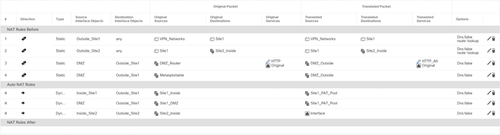
Final NAT policy

NAT Configuration Site 1
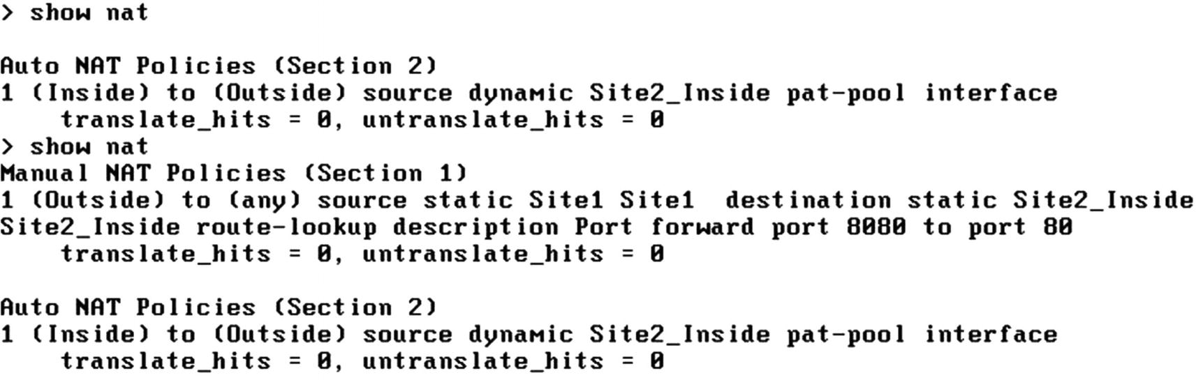
NAT Configuration Site 2
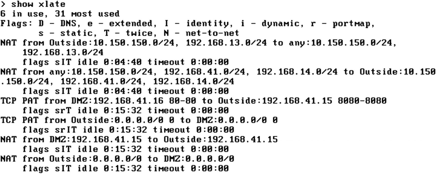
Xlate table with error
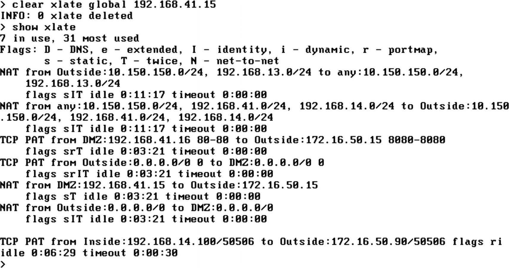
Corrected Xlate table
Static NAT test
Our real test of the NAT exceptions for VPN will be in the “Virtual Private Networks” section.
When we get to the “Troubleshooting” section of this chapter, we will revisit issues with NAT and show you how to identify problems.
In the OSPF section, we configured the firewall to advertise all the routes to the outside router using OSPF. Since we are using NAT, we do not need to advertise them. Advertising them can mask other configuration and security issues. The only network the outside world needs to know about is the outside interface network.
FlexConfig
The graphical interface does not support every feature that was brought over from the ASA yet. The workaround is FlexConfig. FlexConfig allows you to push ASA commands to the Firepower appliances. Cisco provides several templates for common tasks. You only need to fill out the variables and associate FlexConfig to a platform. There are some ASA features that are not currently supported on Firepower, but you can fill most of the gaps in the graphical interface using FlexConfig.
One restriction is you cannot push configuration through FlexConfig, if it is supported in the graphical interface. A major disclaimer you need to be aware of is some configurations will not automatically unconfigure when you remove a policy. In some cases, you need to push an unconfigure object to undo changes.
We will illustrate FlexConfig with EIGRP. As of Firepower 6.6, EIGRP is not supported in the graphical interface. However, it is on the road map for the next major release.
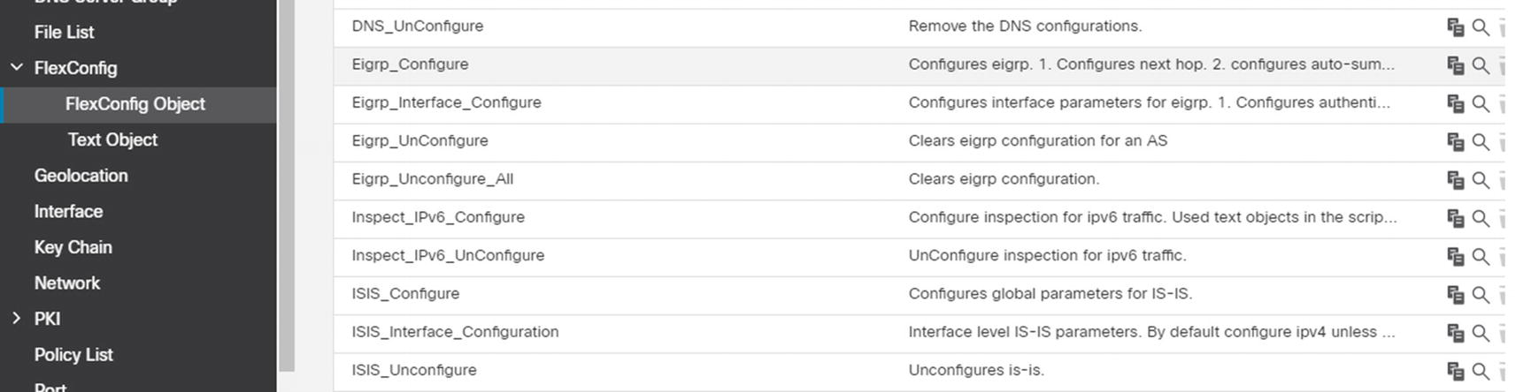
FlexConfig objects
For our example, we will start with EIGRP_Configure but modify it for our environment.
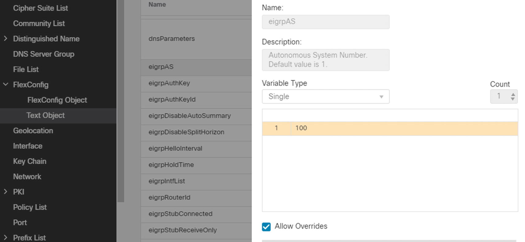
Change AS variable
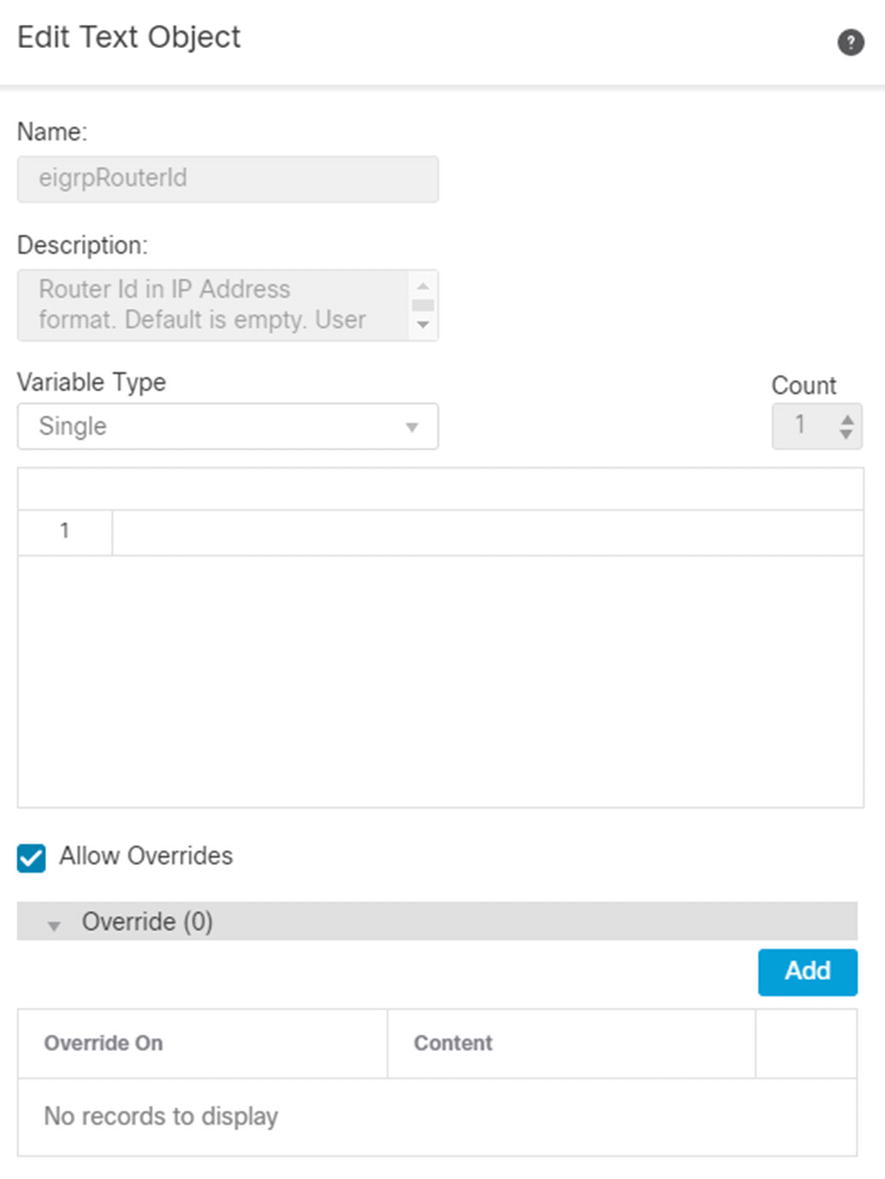
Add override
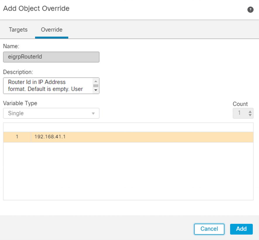
Add system variable override
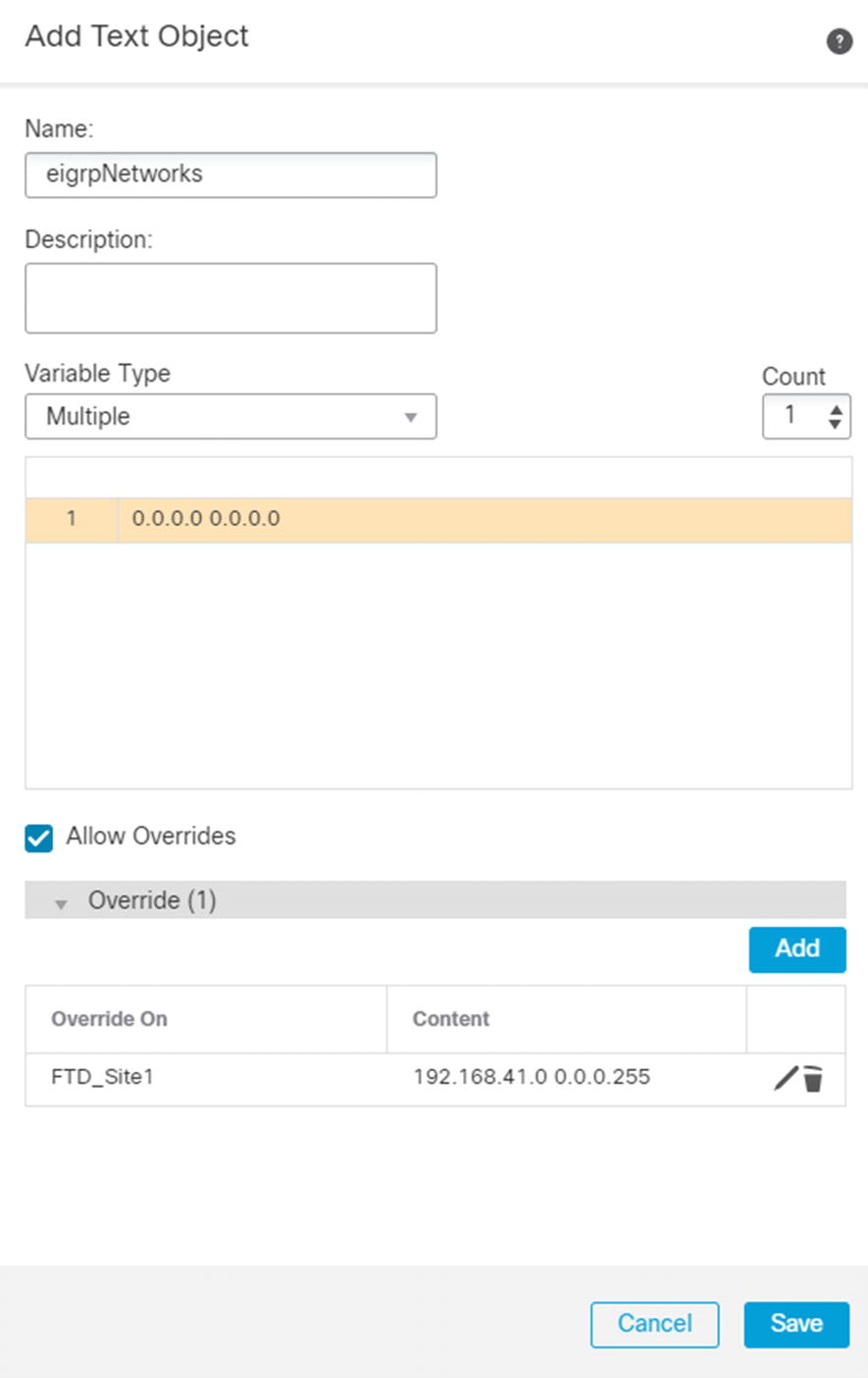
System variable for eigrpNetworks
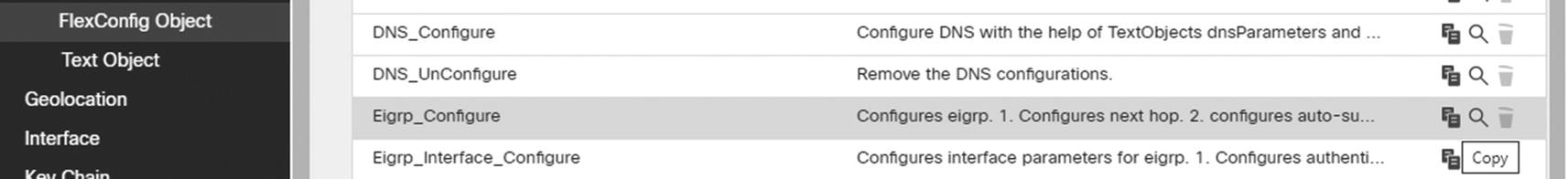
Copy default object
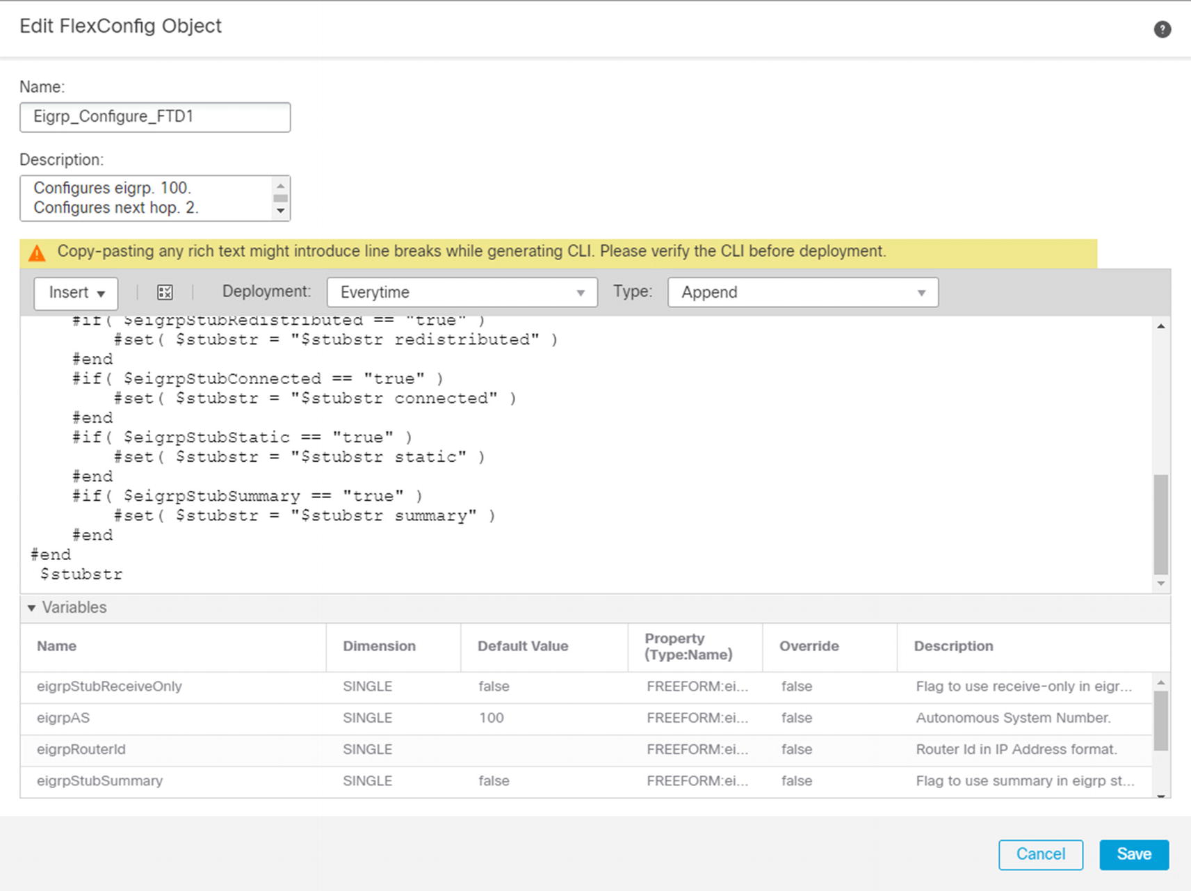
Copy of EIGRP configuration template
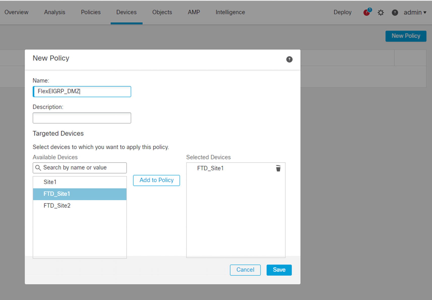
Create FlexConfig policy
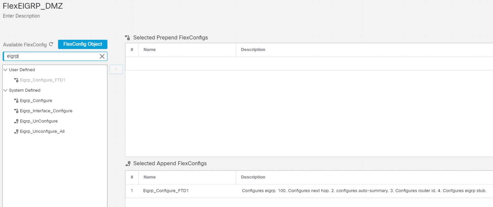
Add objects to policy
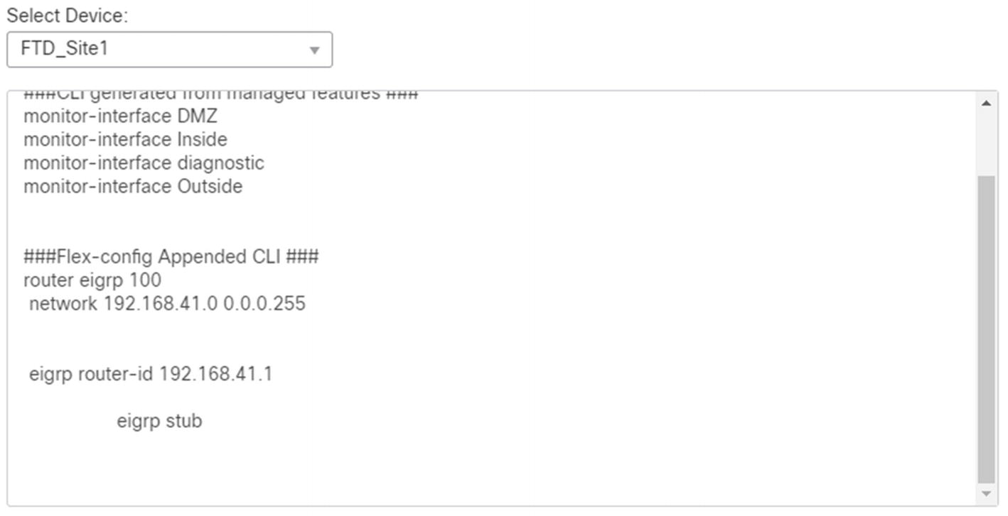
Preview configuration
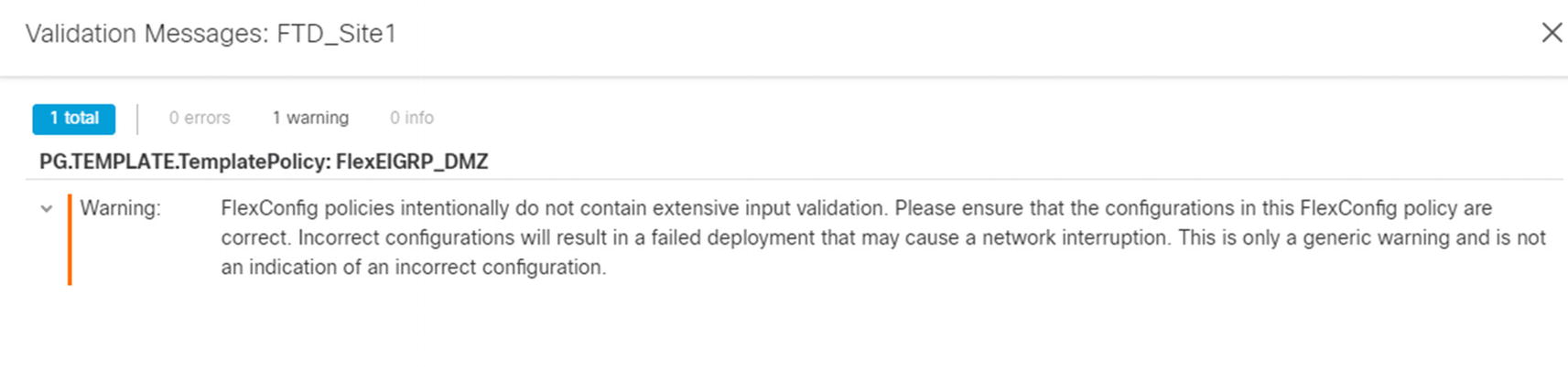
Deploy FlexConfig
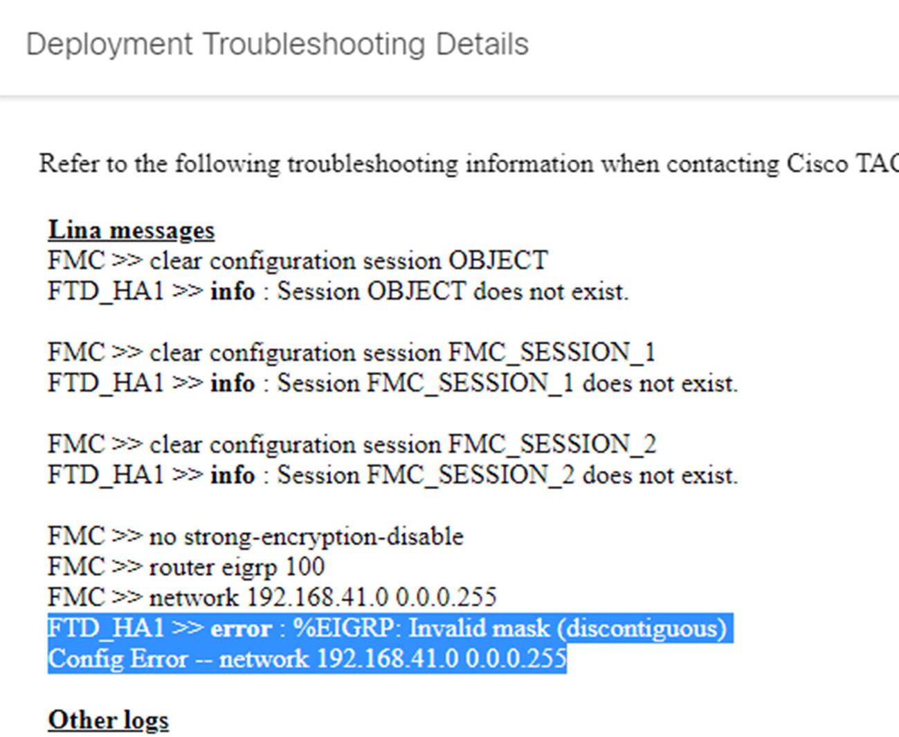
Deployment failure details
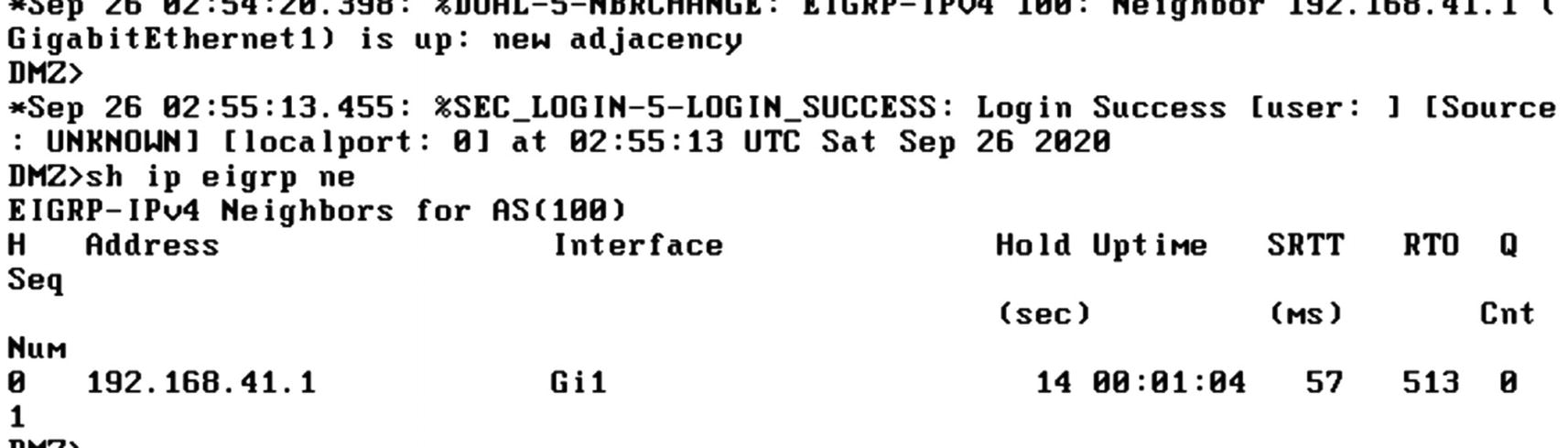
EIGRP neighbor on router
System Configuration and Platform Settings
System configuration and platform settings include many configuration options for securing the management platform and the individual Firepower appliances. The settings under System ➤ Configuration apply to the management console. They do not apply to the firewalls. The firewalls get their settings from Platform Settings under the Devices menu. This allows you to push different settings to platforms, if needed. In this section, we provide an overview of each.
System Configuration Settings
System configuration refers to the Firepower Management Center configuration. Many of these settings apply to how firewalls are managed, but they do not directly apply to the firewalls.
Some common settings for management security are Access List, SNMP, Login Banner, Shell Timeout, User Configuration, and UCAPL/CC Compliance. Access List allows you to configure IP access lists for SMP, SSH, and HTTPS access. SNMP allows you to configure the SNMP version used and the parameters. It is recommended to use SNMPv3 with authentication and privacy. Login Banner configures the banner an administrator will see when logging into the FMC either through the Web or command line. Shell Timeout allows you to set a timeout for the command line or browser. The default timeout values are indefinite for shell and 60 minutes for HTTPS. Most organizations will change those defaults. User Configuration includes settings on password history, lockouts, and maximum concurrent sessions. Some of these settings are new in 6.6. If you are using an older version of the FMC, you will not see them. UCAPL/CC Compliance is for high-security environments. Setting compliance mode runs a script to lock down several settings, and it cannot be undone. You should only use this setting if you are absolutely sure you need to use it. If you use it on the FMC, you also need to set it on the platforms.
A few other common settings are Audit Log, Email Notification, HTTPS Certificate, Access Control Preferences, Intrusion Policy Preferences, Remote Storage Device, and Time Synchronization. Audit Log allows you to send audit and syslog data to an external server. We discuss that in more detail in the Monitoring Overview section. You use Email Notification to configure the connection to the SMTP server that can be used in notification rules. HTTPS Certificate is how you configure the HTTPS certificate for the FMC’s management interface. It is recommended that you change the certificate from the self-signed certificate to a trusted certificate. A recent issue with the self-signed certificate is that it was created in a way that is rejected by Safari on macOS. Unfortunately, there are also some issues with generating a certificate from trusted certificate authorities on Firepower. The HTTPS certificate must have basic constraints marked as critical. Some certificate authorities do not support this, and you need to jump through hoops to install the certificate through the command line. The HTTPS Certificate page allows you to enable client certificates. This will force certificate authentication for administrators. Only check this if you have already configured external authentication to allow certificates. Access Control and Intrusion Policy Preferences are really about comments. The default setting is to not allow comments when you change the policies. Optional will give administrators a box where they can add a comment or cancel. Required forces them to add a comment. Comments can be nice so you can review rules later and know when and why they were created. Remote Storage Device is important for backups. This menu allows you to configure a remote NFS, SMB, or SSH destination for reports and backups.
Platform Settings
Platform settings are the settings that get pushed to the firewall appliances. Even though many things are managed and monitored by the FMC, firewalls have their own management plane and data plane. They can send alerts directly to log destinations without aggregating them at the FMC. If you maintain several firewalls with different requirements, you can push a different policy to each.
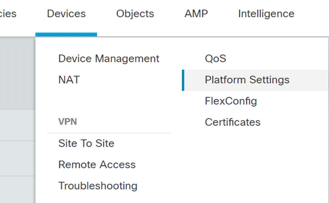
Platform Settings
Once in the Platform Settings menu, click New Policy ➤ Threat Defense Settings. Give the policy a name and assign it to devices. Many of the settings are like what you saw in the “System Configuration” section.
Fragment Settings
ICMP settings allows you to rate limit or block certain ICMP messages. The default is to rate limit ICMP unreachable messages to one per second. That helps mitigate port scanning risks. If you want to explicitly block or permit a type of ICMP, click Add to create a rule. Unless you pre-created it, you will need to create ICMP objects when you create the rule.
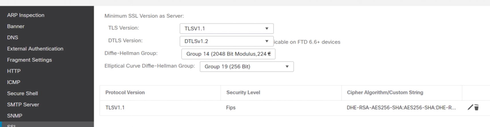
Platform SSL
Syslog settings are interesting. You have a lot more granularity for Syslog from the platform than from the FMC. The Syslog menu is not only Syslog. It also contains rules for sending log messages to email destinations. We go into logging slightly more in the logging and Monitoring Overview section.
Timeouts are important for preventing resource starvation. Other than the console timeout, the default settings in Timeouts meet the needs of most organizations.
External Authentication
Many organizations require external authentication for administrative tasks. Firepower currently supports RADIUS or LDAP . If a user is configured locally, however, the system will use that user and not query RADIUS or LDAP. You can also have a local user that uses external authentication.
To set up external authentication objects, browse to System ➤ Users, and then click the External Authentication tab. This is only for administrative access. This is not where we set up authentication for VPN or NAC.
While you were on the way to External Authentication, you might have noticed User Roles. Firepower provides 11 built-in roles and allows you to create custom roles. Most of these roles only apply to FMC authentication. FTD is limited in the roles. Most of the time, you are only concerned with FMC authorization. FTD authentication and authorization only applies to the CLI. In our example, we will use the built-in roles.

External Authentication
We pre-staged an LDAP object. If you want to use certificate-based authentication, to include smart cards, you need to use LDAP.
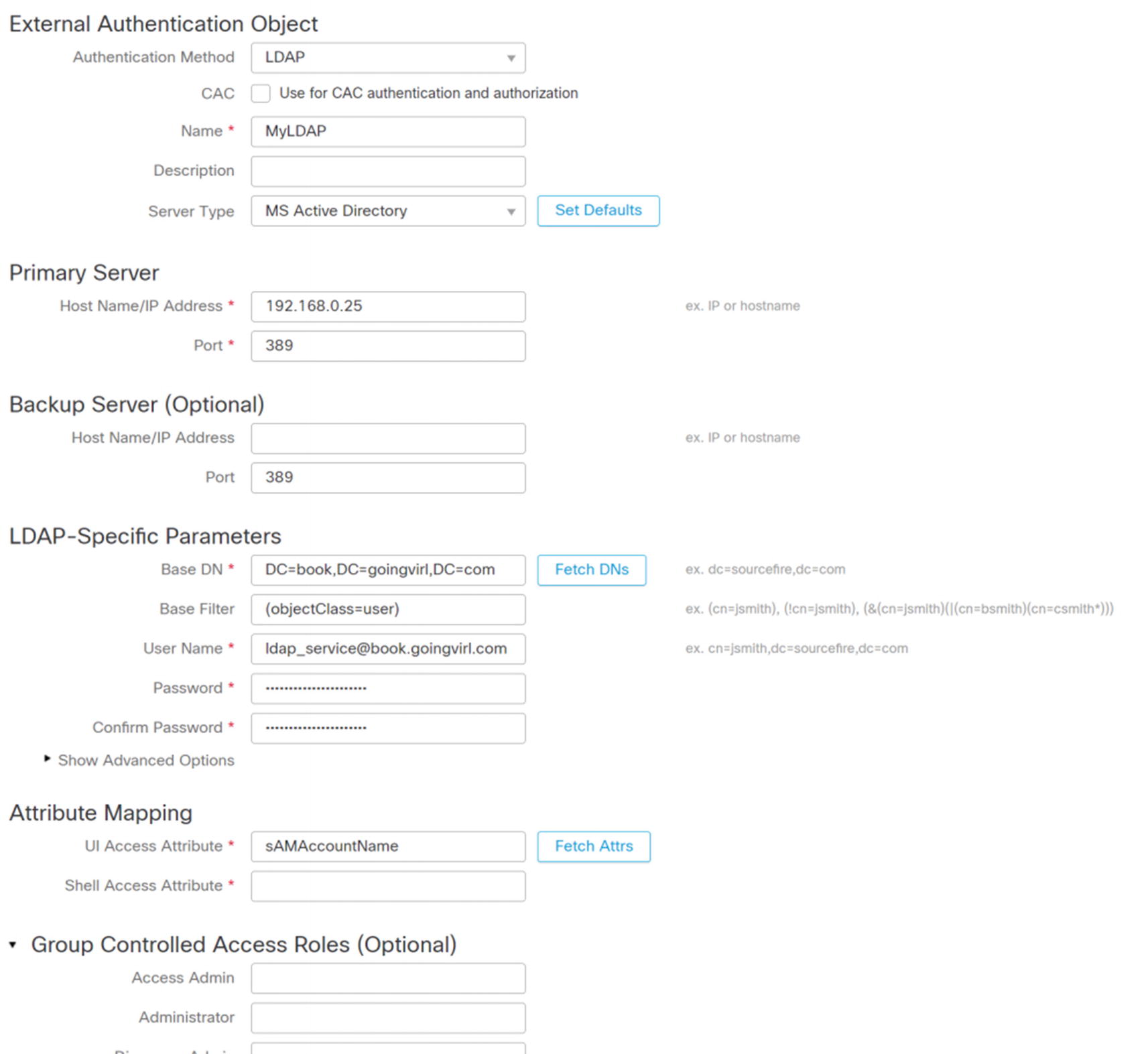
Configure LDAP for authentication
Once you have everything configured, click Test at the bottom right of the frame. An overview of the test results will appear at the top of the screen. Detailed results will be at the bottom under Test Output.

Add RADIUS for external authentication

ISE authorization profile for FMC admin
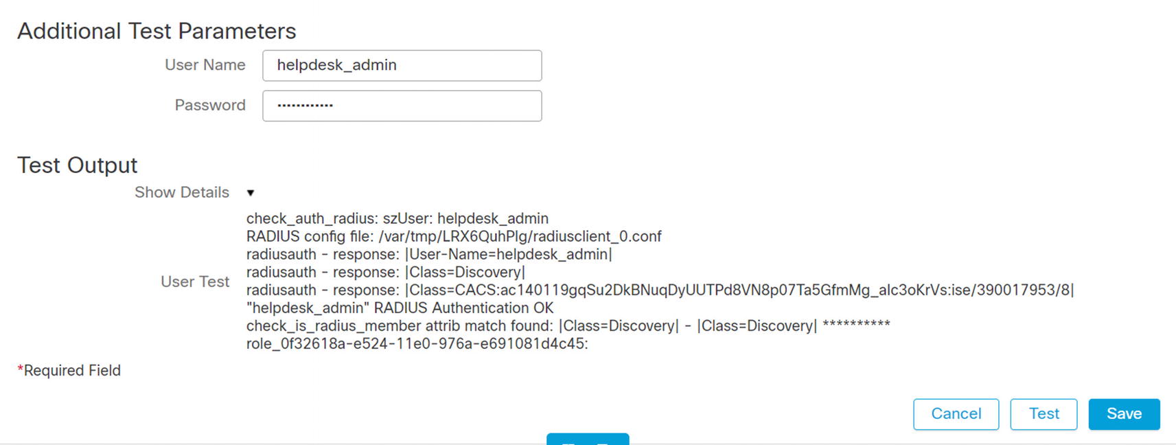
Test RADIUS authentication
Monitoring Overview
Monitoring in Firepower is comprised of a few different components. There is health monitoring for the FMC and the appliances. There is Syslog for each of the platforms. There is an audit log for administrative tasks. Then there is logging for security events from the access and intrusion prevention policies.
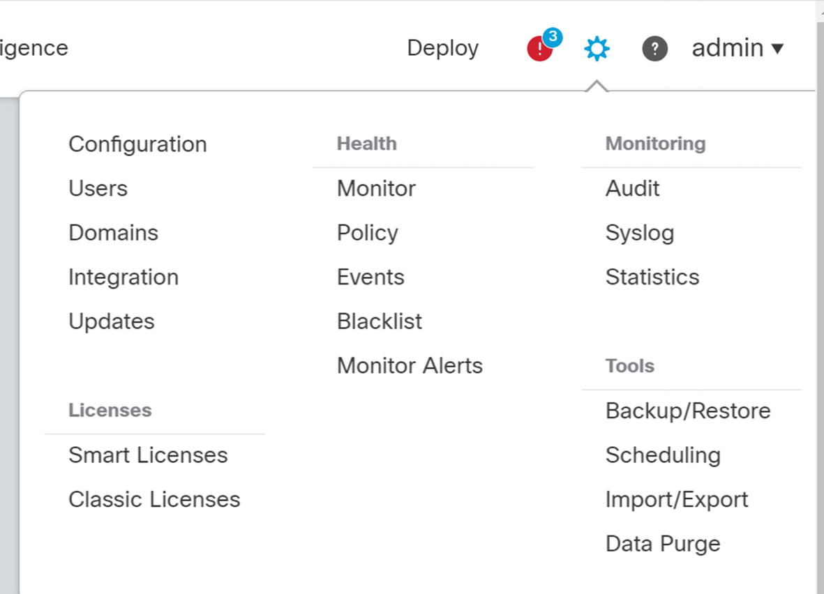
Management Console
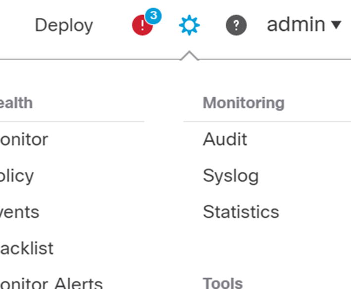
Monitoring menu
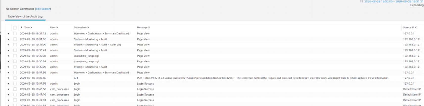
Audit log

FMC Syslog

Analysis of data logs
Remote Syslog
Like many things in the Firepower architecture, remote syslog for the management console is configured separately than for the firewall appliances.
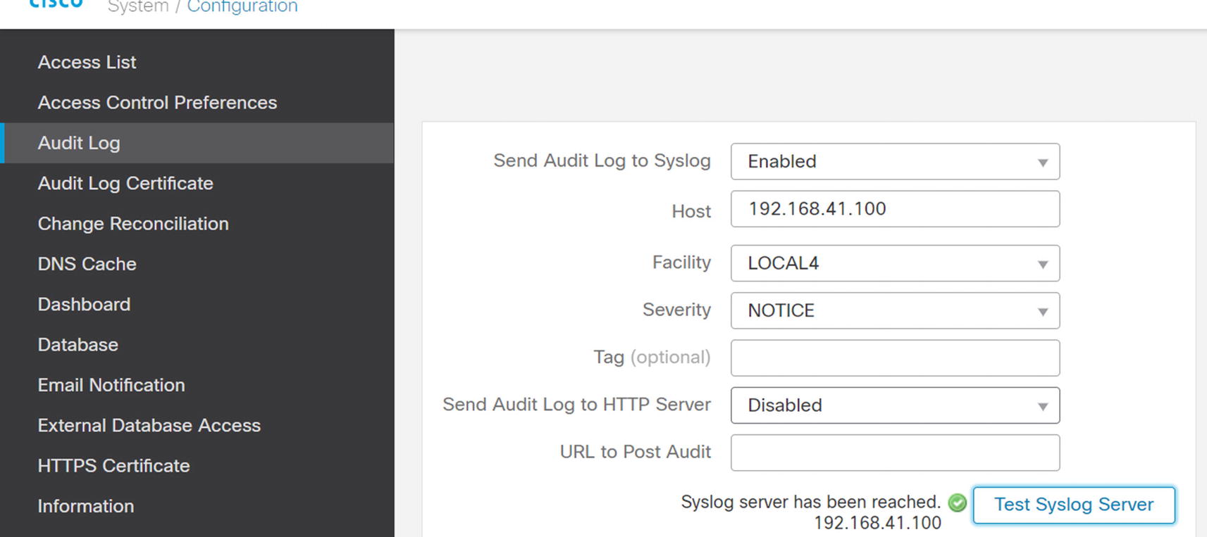
Configure remote audit logging
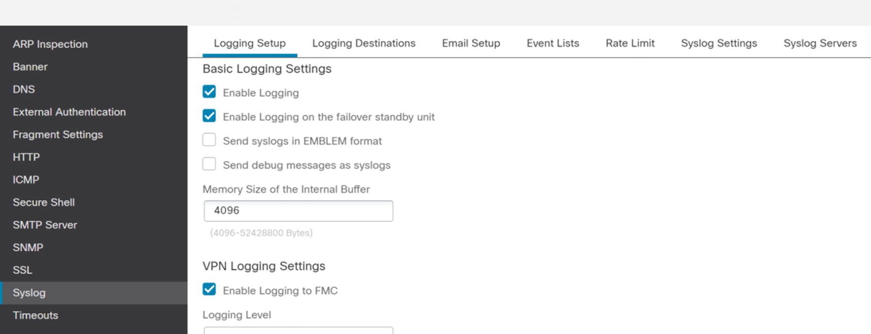
Enable logging on platform
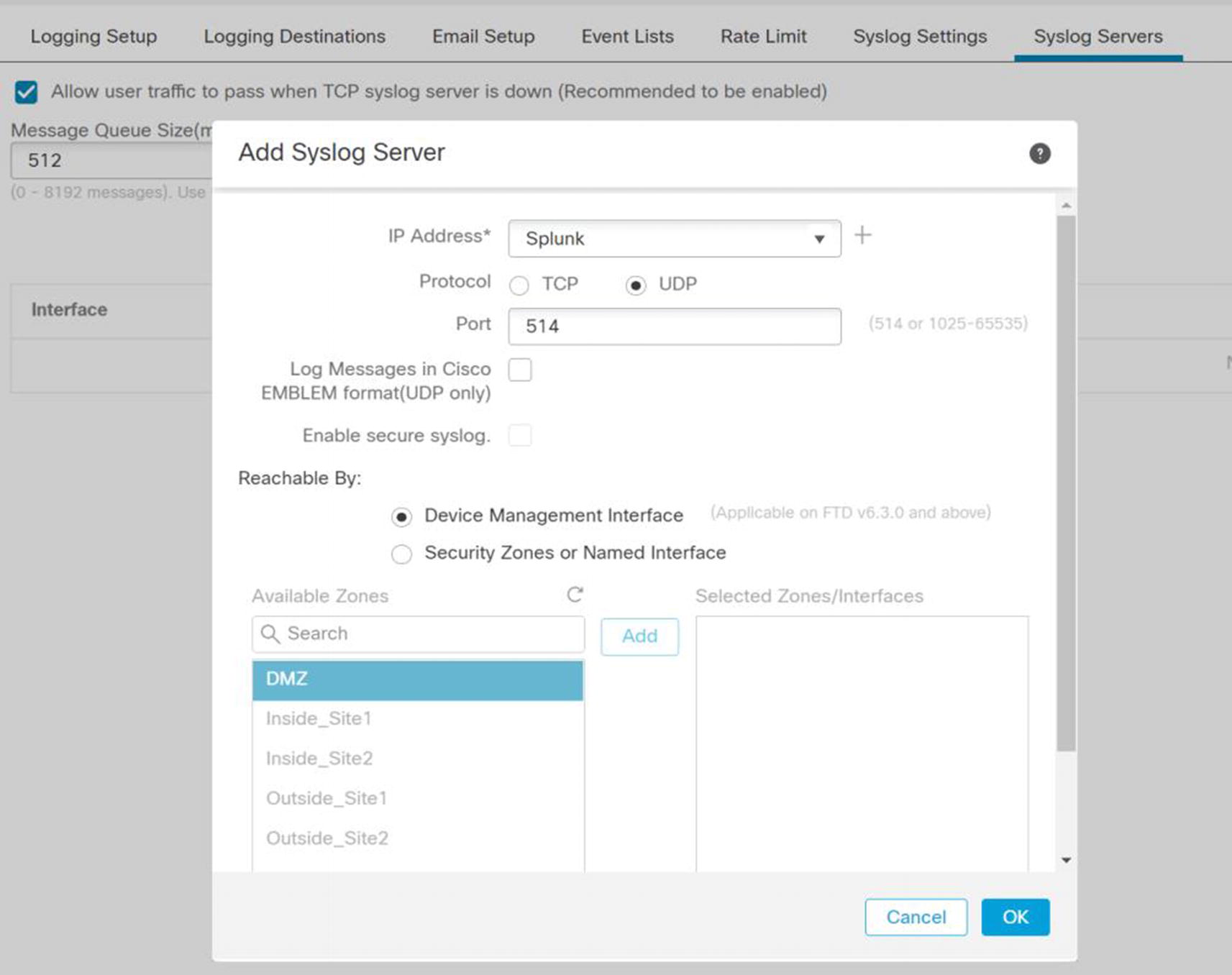
Add syslog server
Once you have configured the filters and format the way you want, save the policy and deploy it to the appliances.
eStreamer
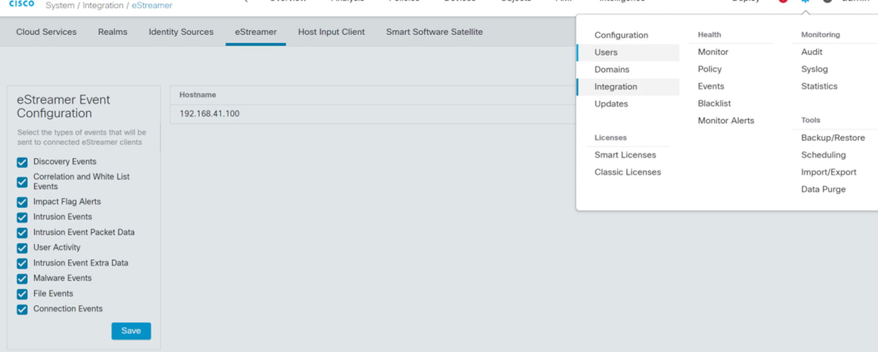
eStreamer configuration
In System ➤ Integration ➤ eStreamer, we need to add the host for our monitoring server. When you configure the host, it will ask for an IP/hostname and a password. After adding the host, there is a download button to the right of the hostname or IP address. That will download a certificate. You need the certificate and password when configuring eNcore on the logging server.

Splunk eNcore configuration
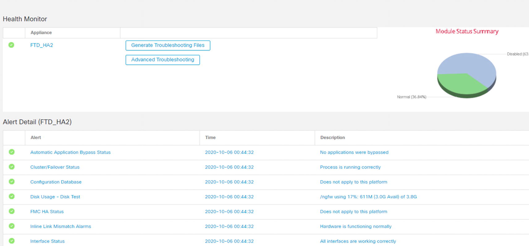
Health Policies
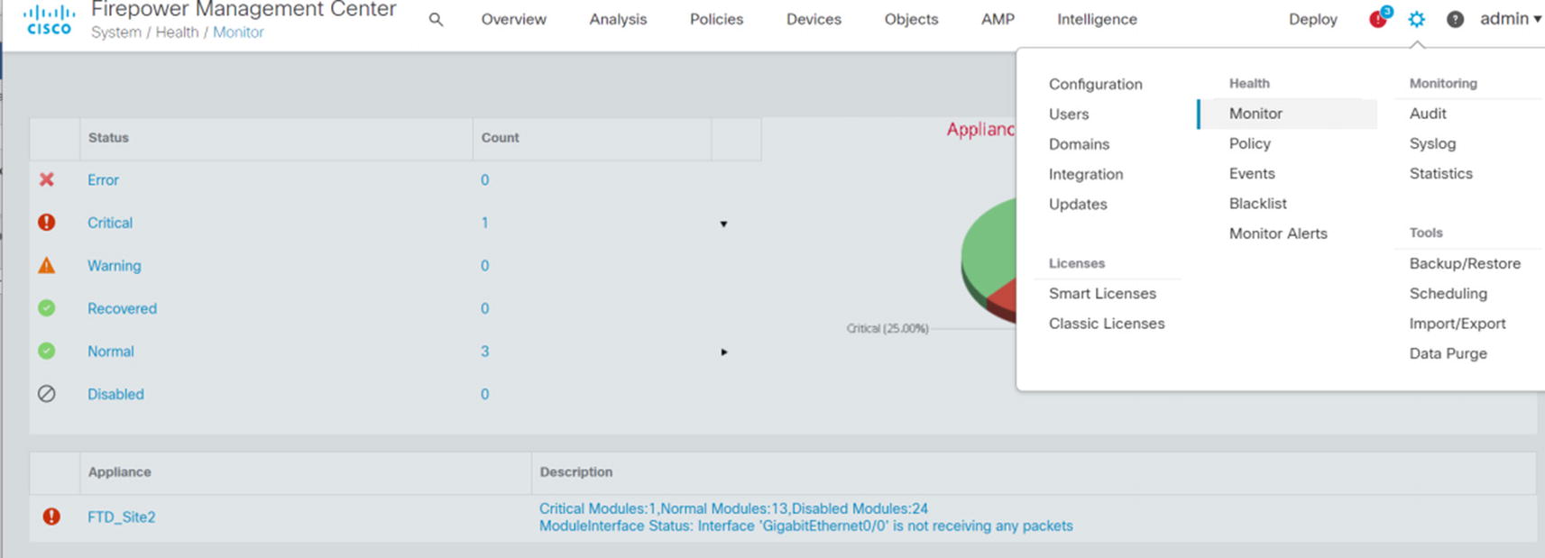
Health monitor
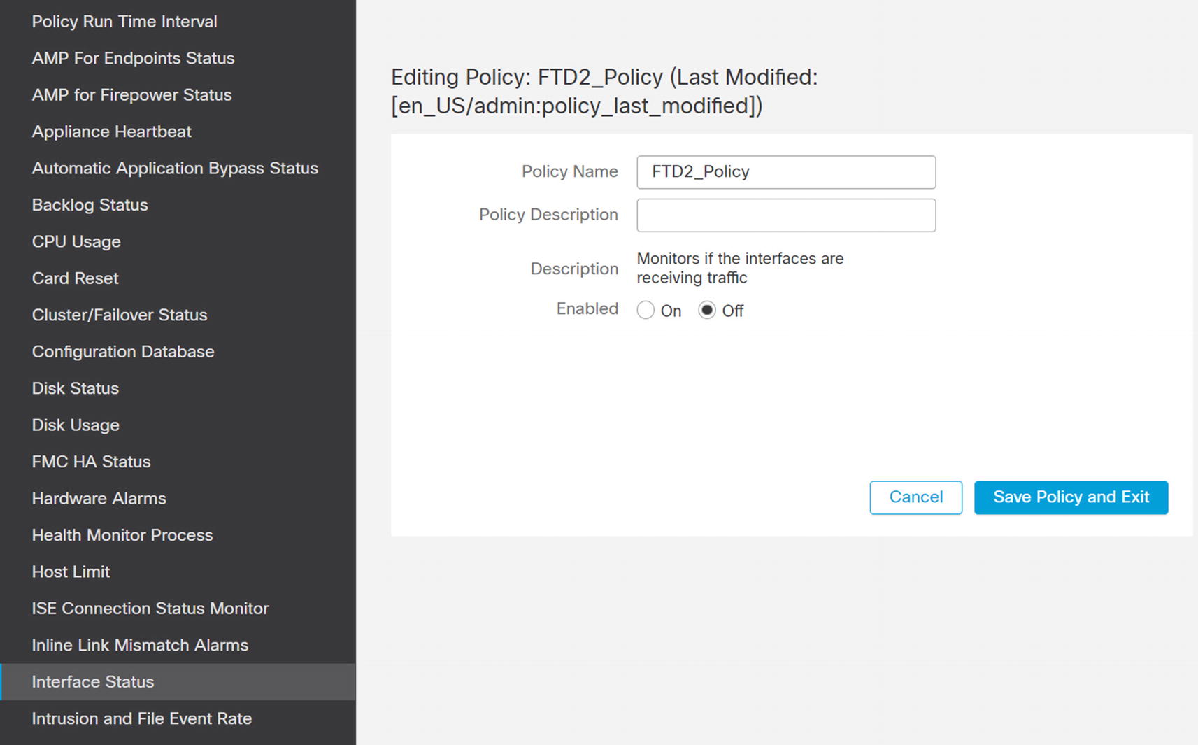
Disable interface monitoring

Blacklist from monitoring
Access Policies
Access policies are the meat of a firewall. Access policies determine what traffic is allowed through the system. Next-generation firewalls do not simply look at ports and protocols; they can do deep inspection. This can help protect against exploits that use channels which are normally allowed.
The Firepower system includes capabilities to prefilter, inspect encrypted traffic, inspect files, use security intelligence, create rules based on security tags, and create rules based on user identity. In this section, we focus on rules based on ports and protocols and applications.
Baselining and Discovery
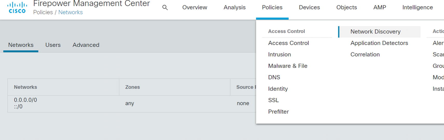
Network Discovery
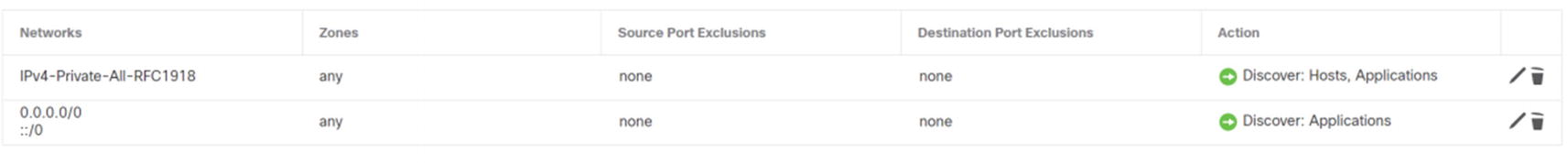
Add host discovery

List of discovered hosts
Access Policy Basics
A basic access policy is extremely similar to a router access list. Just like router access lists, a firewall policy is processed top down. When a rule is matched, it stops and executes that action for the rule. Rules based on source and destination addresses and ports are processed quickly, so they are useful when you don’t need deeper inspection.
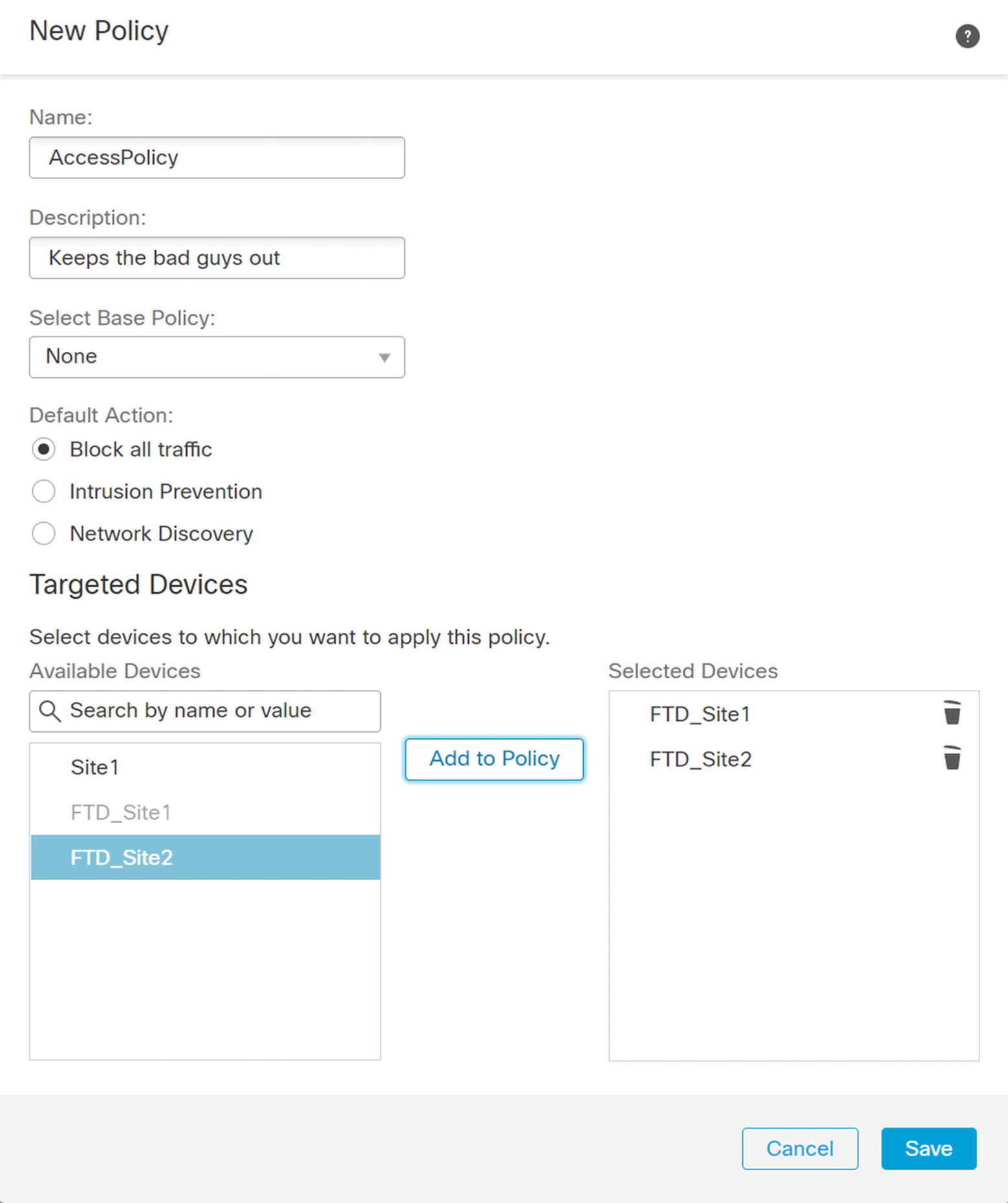
Create new access policy

Allow inside traffic
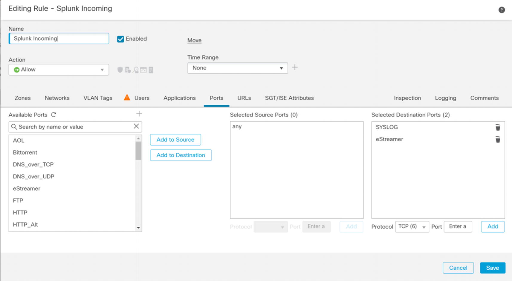
Splunk rule

Metasploitable incoming
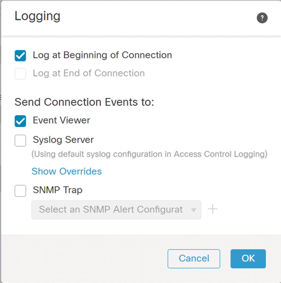
Logging on default action
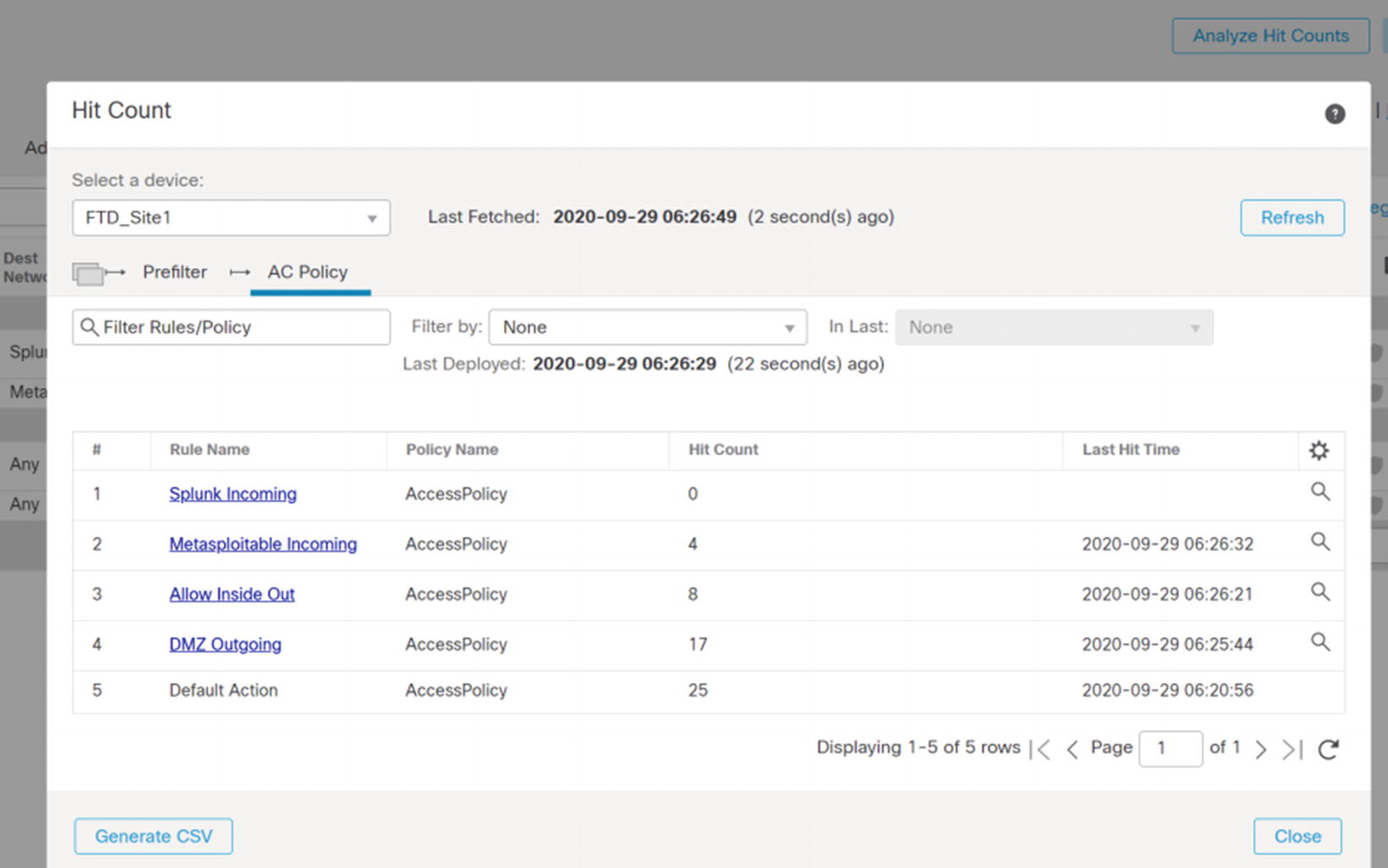
Analyze Hit Counts
Application-Based Rules
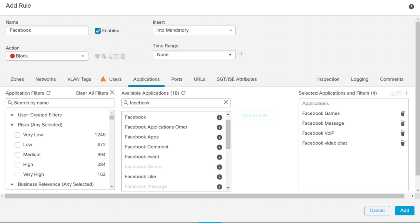
Facebook rule
Next, we create a rule to block certain types of Facebook traffic. This capability eliminates the issue of companies wanting employees to be able to get important information from Facebook, but not wanting them to use the other features. One limitation with these types of rules is they often require inspection of data that is often encrypted. A solution is to use an SSL policy to decrypt traffic. However, that takes additional resources and configuration. Everything that is not blocked will be evaluated by a later rule. We also want to know who is violating this rule, so we log it. We show part of this example in Figure 21-89.
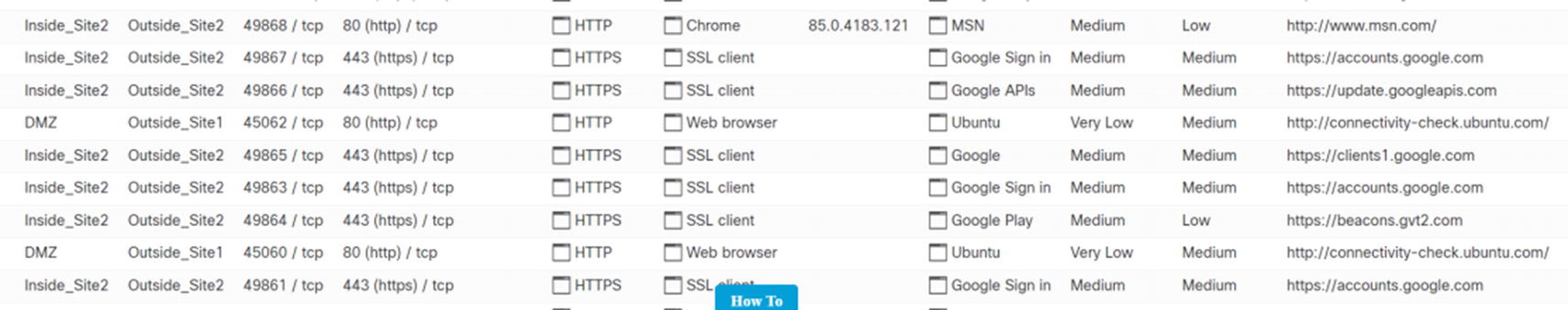
Connection events
Intrusion Policies Introduction
Intrusion policies take inspection one step deeper. They will inspect information inside packet headers, the body, or summary data about connections. They can block traffic that is likely malicious even if the access control policy allows it. However, you need to assign a Threat license to a firewall to use this feature.
If you remember, we configured the rule for the Metasploitable host wide open. Let’s see how it fares against Firepower’s intrusion detection component.
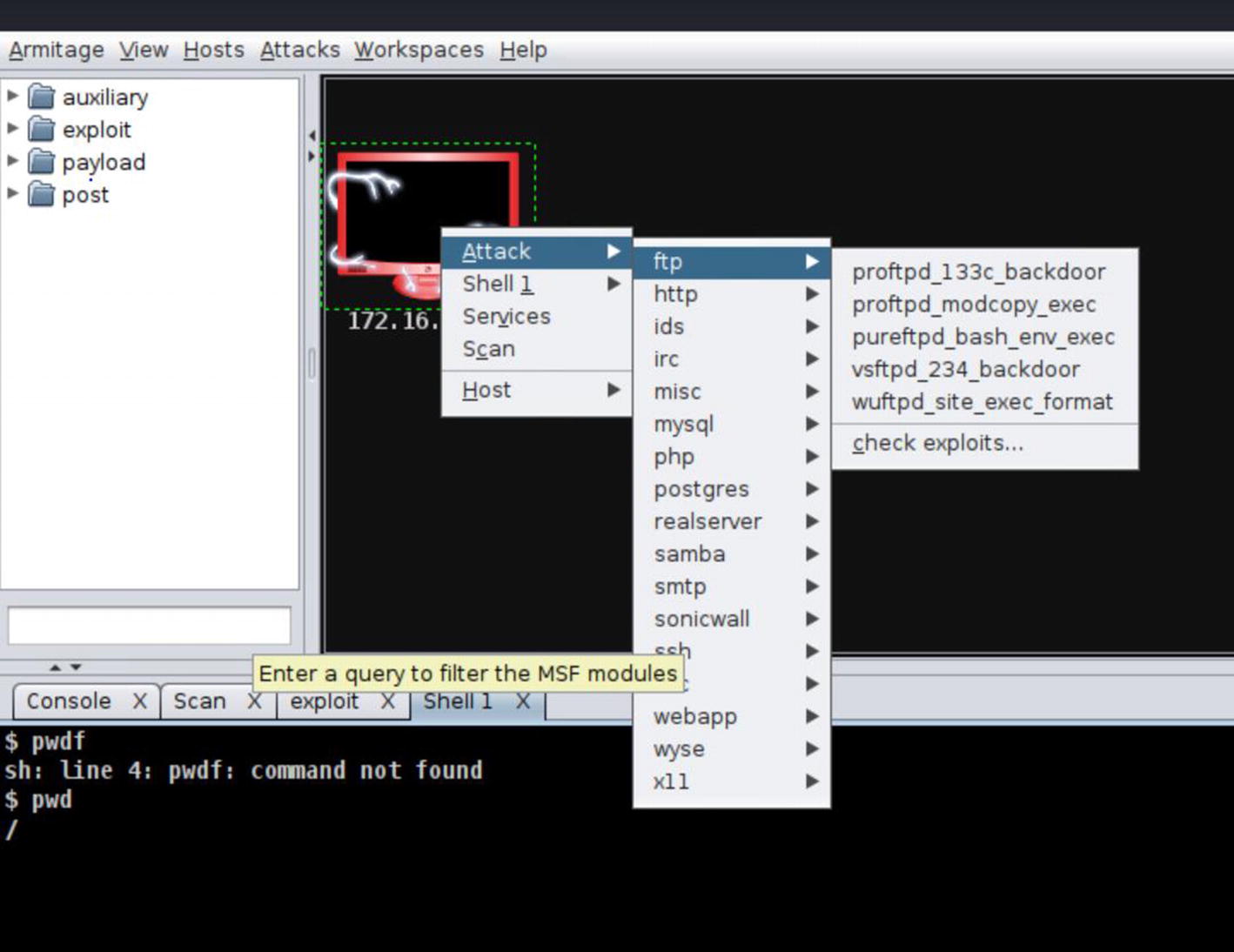
Root shell exploit

Intrusion rule

Exploit failed
Intrusion Policy Tuning
In the previous section, we used an intrusion policy without explaining it. Using intrusion policies without understanding them is a major cause of false positives. False positives occur when you get an alert for legitimate traffic. When there are a lot of false positives, administrators stop paying attention to the alerts. We need to tune a few things to remove false positives.
It is base practice to create a new policy and tune it for your organization. You will start with one of Cisco’s policies as the base. When Cisco adds new rules to the base policy, they will be pushed to your policy. This allows you to disable or adjust rules without losing rule set updates. If you don’t know where to start, Balanced Security and Connectivity is a good place. If testing shows that it is not restrictive enough, you can move to a more restrictive base policy. If it only needs slight adjustment, you can reenable rules that are disabled by default. The same concept applies to make a policy more permissive.
Before we create a new policy, we will look at the variable set. A variable set is used to fill in variables in rules. They are accessed through Objects ➤ Object Management ➤ Variable Set. The variables define networks and ports. Common variables are $HOME_NET and $EXTERNAL_NET.
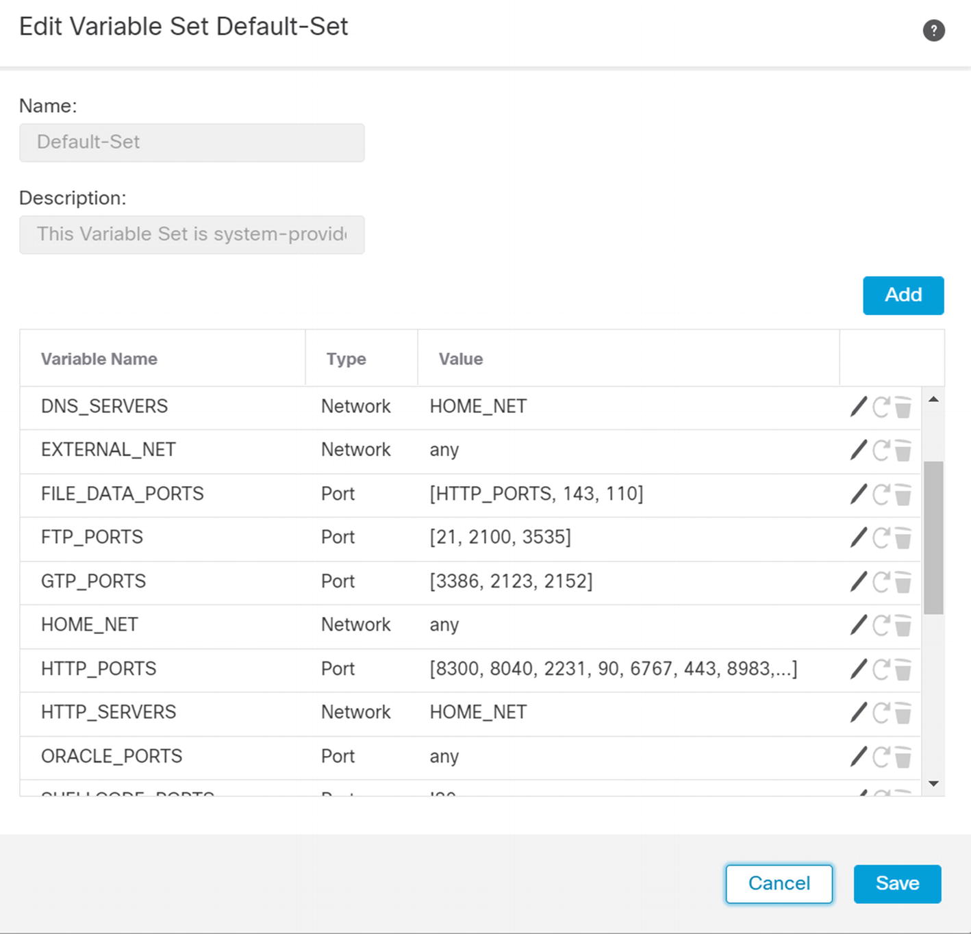
Default intrusion prevention variables

Edit HOME_NET variable
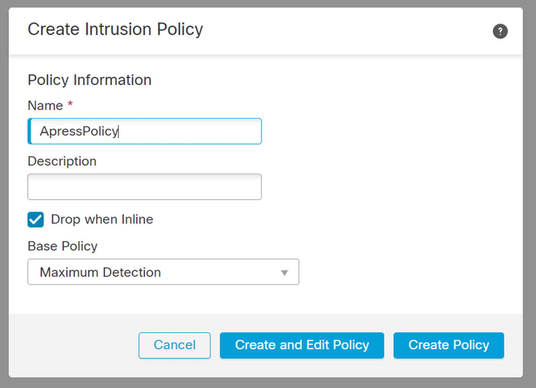
Create intrusion policy
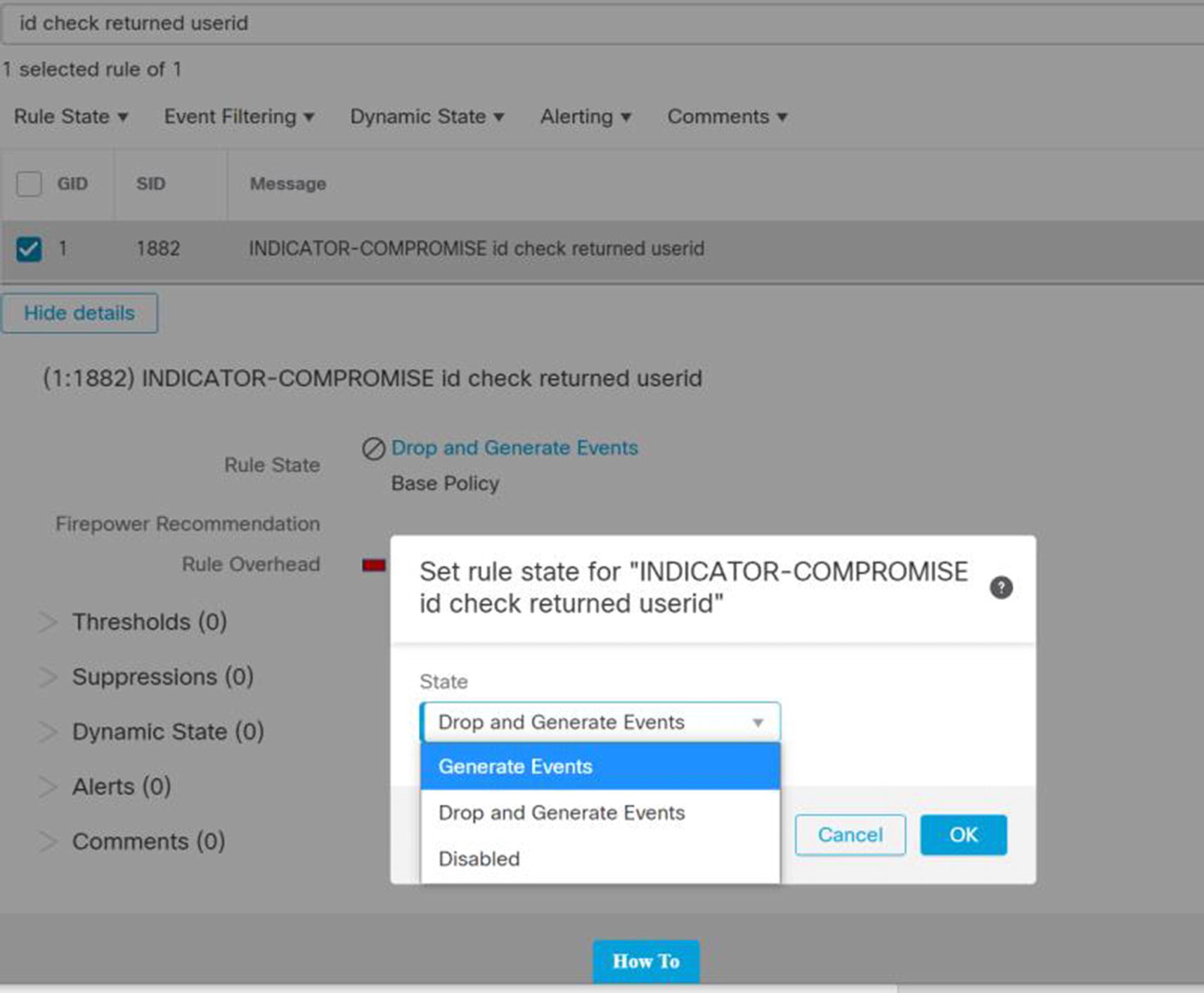
Change rule in intrusion policy
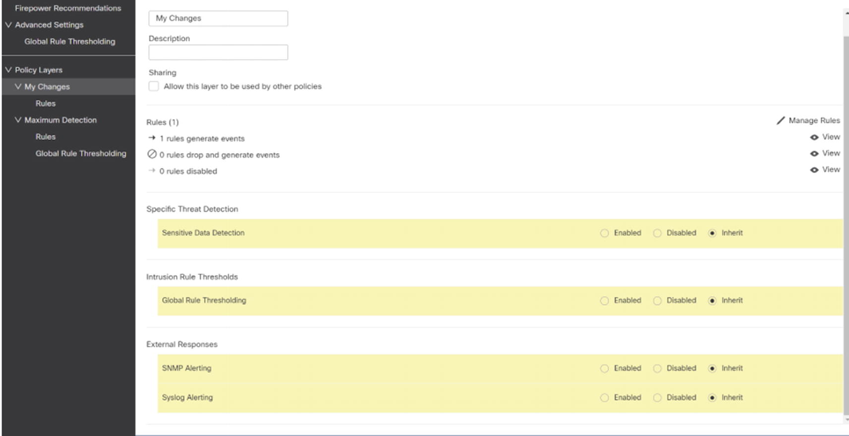
My Changes
The final step is to associate the custom policy with access control policy rules. In practical application, you should create your intrusion policy first. Otherwise, you may have several rules to update.
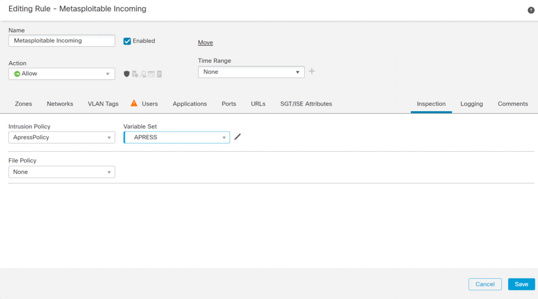
Update access rule for intrusion policy

Details of alert
Virtual Private Networks
Virtual Private Networks (VPNs) provide an extension to an organization’s infrastructure. It gives the appearance that networks are directly connected even if they are across the world. In most cases, the connections are encrypted. Encryption is important for ensuring confidentiality and integrity of the data. In this section, we discuss site-to-site and remote access VPNs.
Site to Site
VPNs between sites usually use IPsec. We can configure VPNs to authenticate the tunnels using pre-shared keys (PSKs) or certificates. PSKs are easier to configure, but using PSKs is less secure than using correctly configured certificates.
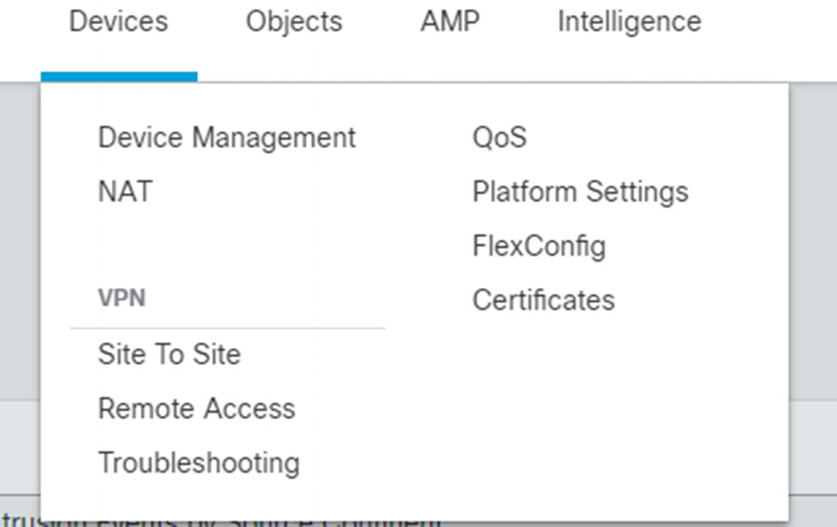
Site-to-site VPN menu
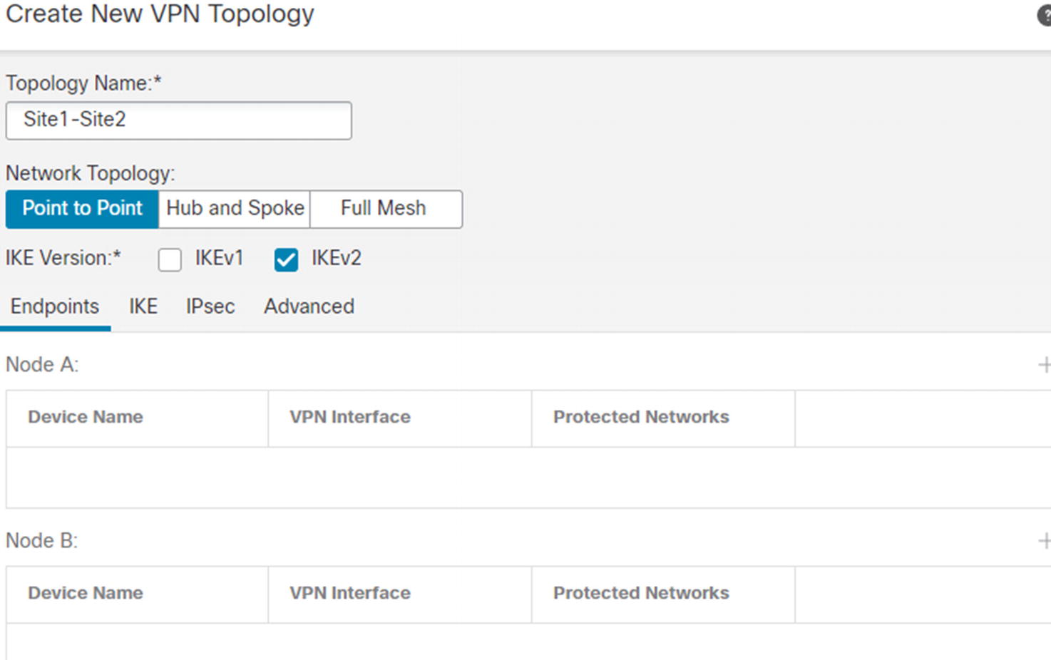
Site-to-site VPN initial page
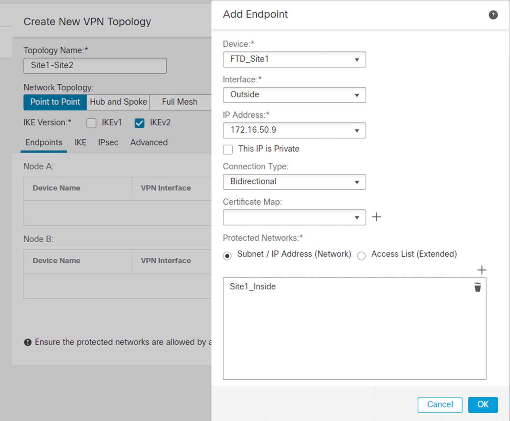
Add node to VPN
The checkbox for private IPs is really asking if the IP is behind a NAT boundary. If the IP will be NATed by another device, the NAT-T protocol is used to assist the VPN. Certificate maps are used to pull information out of certificates for authenticating and authorizing devices. Protected networks are the networks you want to advertise to the other side.

Site-to-site IKE configuration
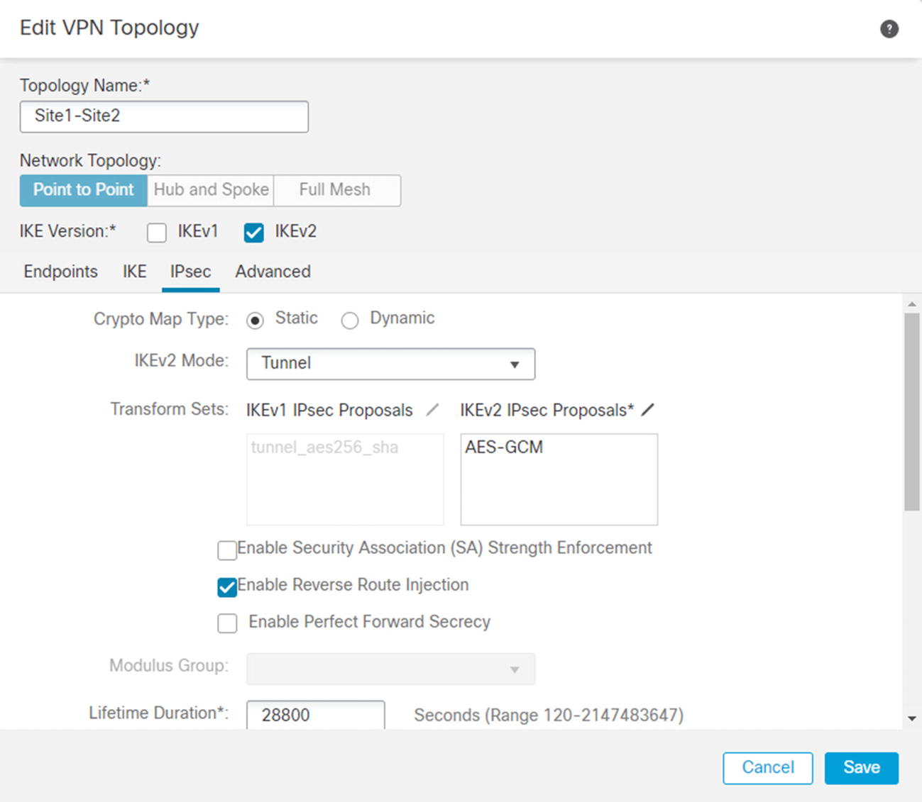
IPsec tab
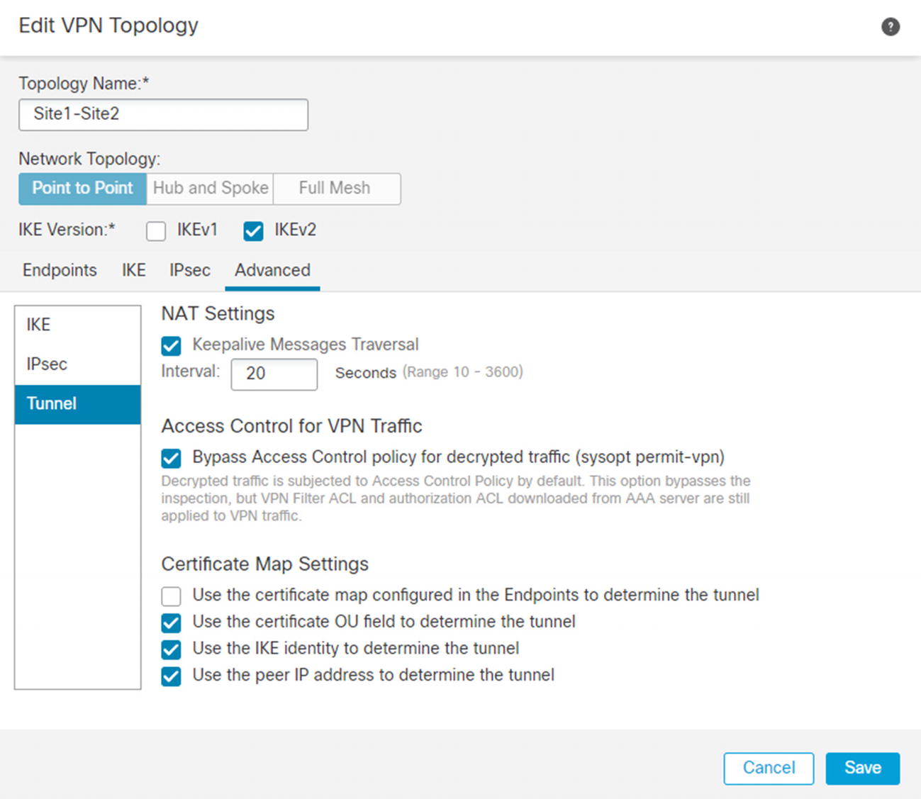
Bypass access controls

Virtual routes are learned over VPN

Tunnel information
Certificate authentication is more secure but is slightly more complicated. We need to create a trustpoint that the devices will use. If both sides of the VPN are managed in the same FMC domain, you can only select a single trustpoint that both devices use. Some trustpoints use autoenrollment and will generate a private key and a certificate for a device when the trustpoint is associated with a device. If you use an autoenrollment protocol, such as SCEP, the process is easy. Many of us use manual enrollment. The process for manual enrollment on the FMC is a bit convoluted.
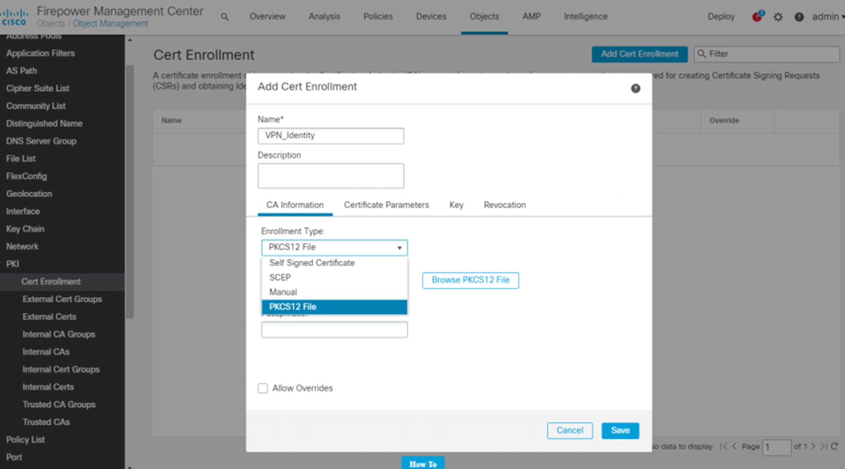
We will set up the certificate-based site-to-site VPN slightly wrong at first. We are doing this so we can show you what the error looks like in the logs. Browse to Objects ➤ Object Management ➤ PKI ➤ Cert Enrollment. When you click Add Cert Enrollment, you see a few options. PKCS12 is a type of offline manual enrollment. We will be using that option in our example.
We will generate the PKCS12 file using OpenSSL on a Linux system. You could also use the shell on the FMC as it is a Linux variant.

Add PKCS12 file

Add enrollment to FTD

Certificate error

VPN certificate authentication

VPN certificate authentication error

PKI object override
With the override in place, go back to Device ➤ Certificates and reenroll the trustpoint for FTD2. Then configure the VPN back to certificate-based authentication. When making changes to IKEv2, you may need to go into the command line and clear the security association with clear crypto ikev2 sa. Now that we have the override in place, the certificate-authenticated VPN will work. We deploy the new configuration. After generating traffic from internal hosts, we see the VPN session establish without error.
For additional security, we could have also used certificate maps.
Remote Access
Remote access VPNs allow end users to connect to their organization’s internal network. The two main types of remote access VPNs are IPsec and SSL VPNs. Even though IPsec is still in use, SSL VPNs are more common. One reason is that it is easier for firewalls and NAT boundaries to handle SSL traffic than it is for IPsec. In our example, we will configure an SSL VPN.
The first step we need to do is create a profile that will be pushed to the clients. ASAs had an option to configure the client profile as part of the VPN wizard. As of Firepower 6.6, that feature does not exist, and we need to create the profile offline. The tool to create a profile is called the AnyConnect Profile Editor. If you search Cisco software downloads for AnyConnect, you will see an installer for the profile editor as an option. While you are on the page to download AnyConnect files, you need to download the head-end package for AnyConnect. There are options for Windows, Mac, and Linux.

Create client VPN profile
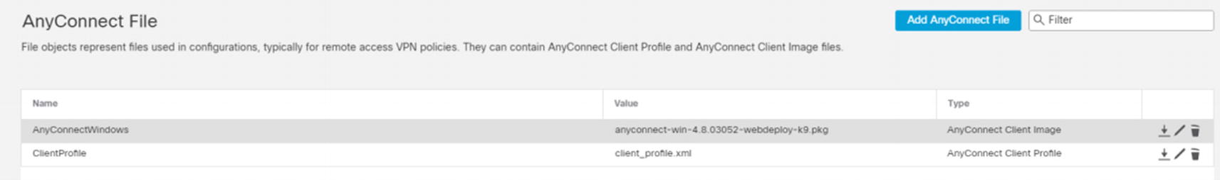
AnyConnect file

Address pool
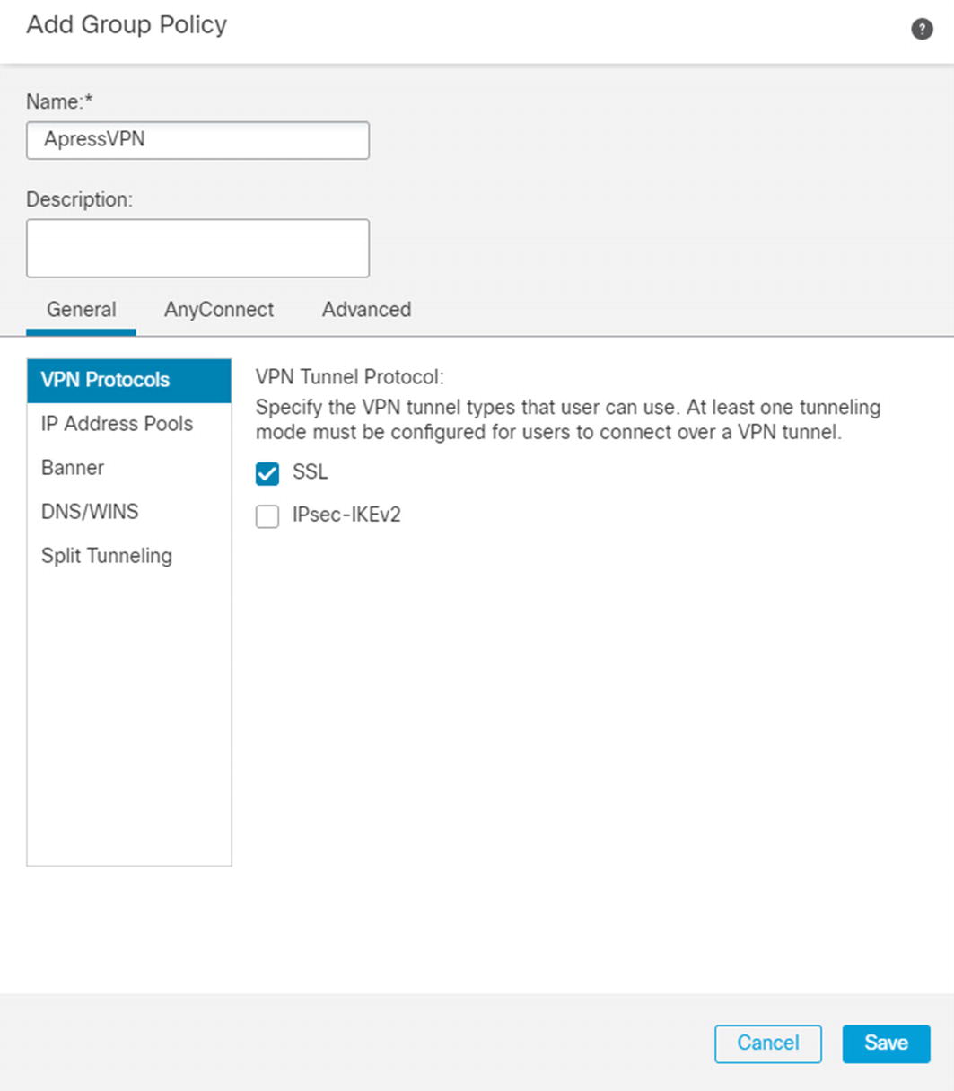
Configure VPN group policy

Add RADIUS for VPN

Add remote access VPN
On the next page, we are selecting AAA only. Other options are certificate only or AAA and certificate. If you select certificate only, the system will verify that it trusts your certificate and then send your user information from the certificate to RADIUS for authorization.
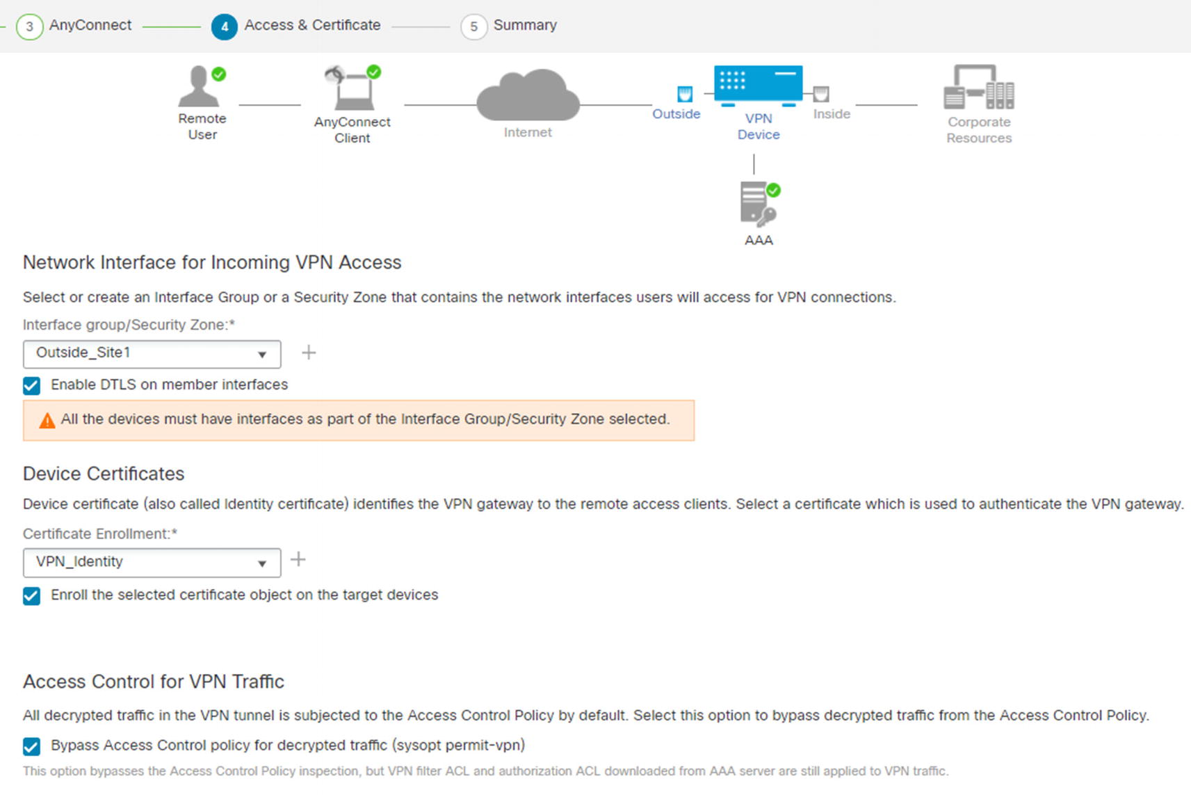
Access & Certificate
We selected to bypass the access control policy for decrypted traffic. That does not mean that there is not any access control. Filters on the group policy or access control lists pushed from ISE are still applied. If you choose not to check this box, you need to create access policy rules for allowed traffic from clients using Firepower access control policies.
Before we test the VPN, we need to set up everything in ISE. RADIUS requests will come from the firewall itself and not the FMC. We need to create a network resource for the Site 1 FTD appliance.
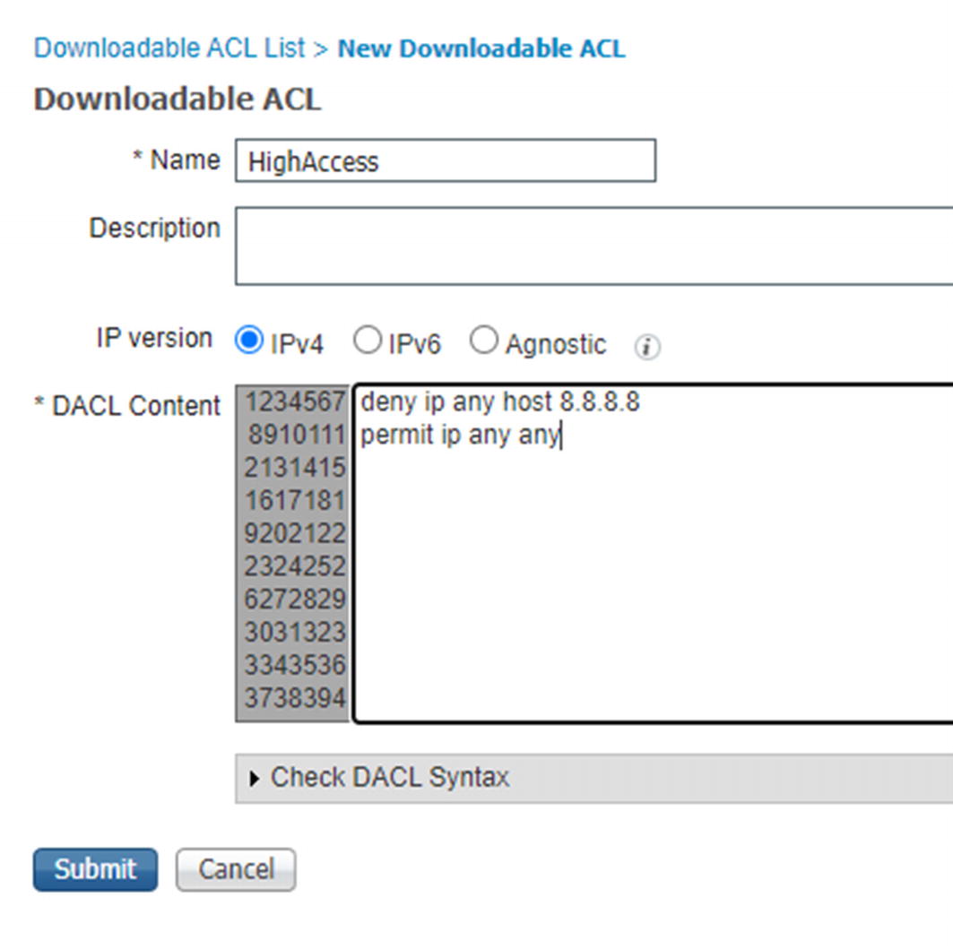
Create dACL
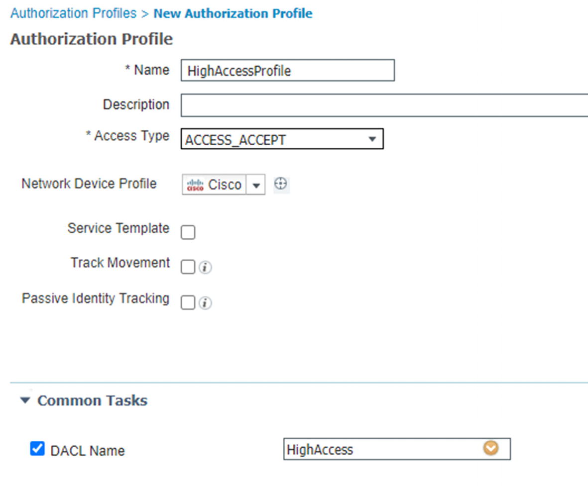
Authorization profile
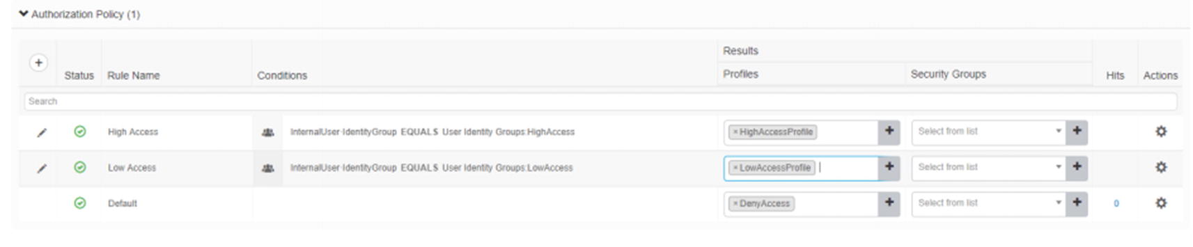
VPN authorization rules

RADIUS Live Logs
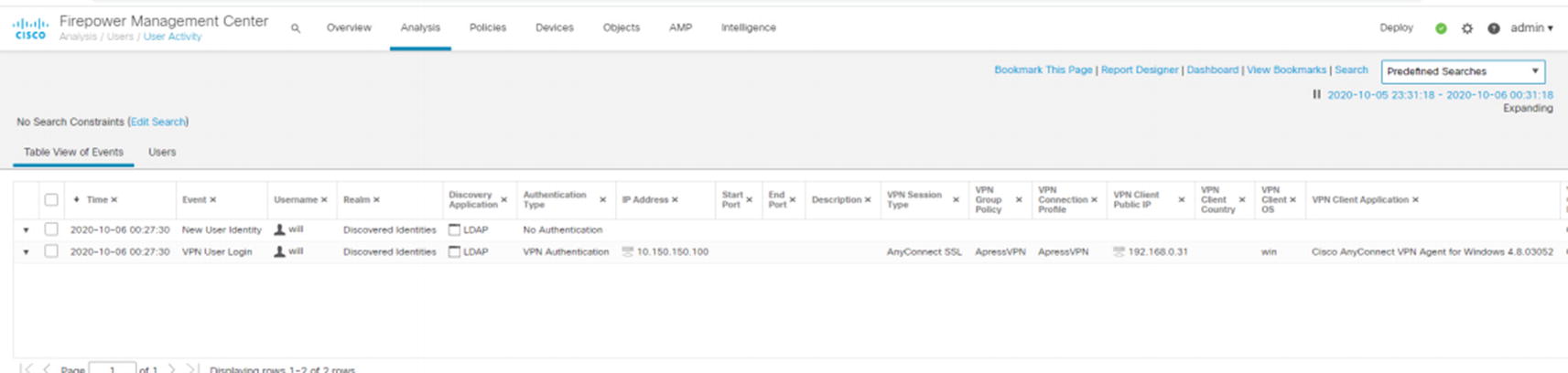
User information

Dynamic access list
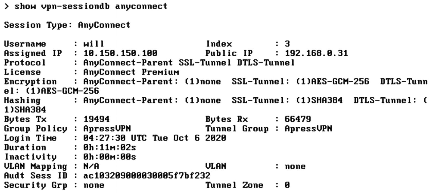
Show VPN output
Troubleshooting
Device troubleshooting
Troubleshooting page
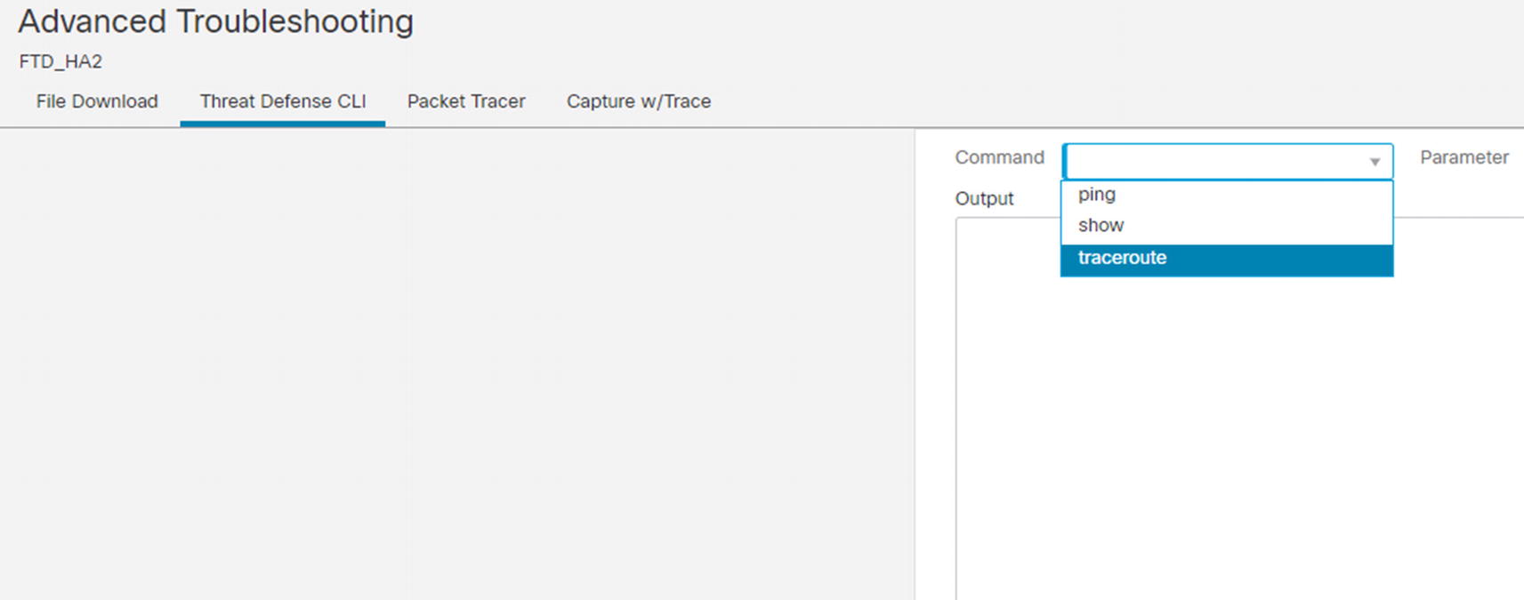
Advanced Troubleshooting page
The CLI page is a nice way to run commands against the FTD, but you need to know the exact command and it only supports ping, show, and traceroute. It does not support auto-completion or context-sensitive help. If you are not certain of the exact command, the CLI offers more flexibility.
Packet Tracer allows you to inject a test packet to an interface and trace what happens. We show an Packet Tracer example in Figure 21-132. It will tell you if it hit an access control policy or NAT policy and the disposition of the packet. It is useful in what if scenarios.
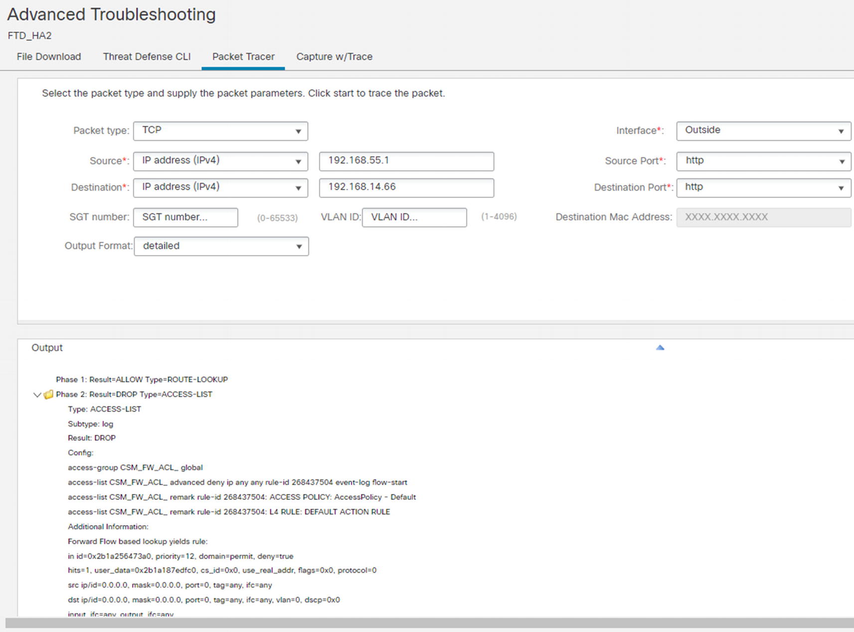
Packet Tracer
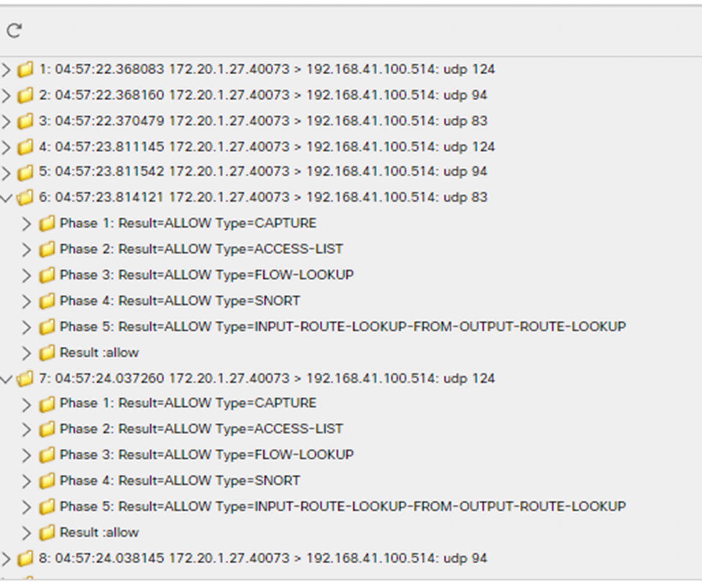
Capture with trace output
Summary
This was a massive chapter, but it only scraped the tip of the iceberg on the features available on the Firepower system. Firepower is the combination of several other products. The two main influences of Firepower are ASA and Sourcefire Defense Center, but other products show their influence in the framework.