Have you ever troubleshot a network issue for hours, racking your brain, only to find out that someone pulled a cable slightly out of the port while working in a rack? This chapter focuses on problems at layer 1—the physical layer—and how this layer is overlooked when network problems are experienced. A common example is a cable with a loose connection. I once left a network down for two days before actually looking at the port to determine the issue, which was a cable with a loose connection. It is very easy for you to blame your commercial carrier, but before you do so, you should exhaust all fault possibilities. This chapter discusses the importance of the physical medium in network design. Topics begin with the physical medium, including transmission media such as copper, coaxial cable, and fiber-optic cable and the standards associated with each. Next, the Ethernet, duplex communication systems, autonegotiation, Unidirectional Link Detection (UDLD), and common issues associated with layer 1 are covered.
Layer 1
The physical medium , or transmission medium, refers to the way in which data is transferred across networks. Think of the physical medium as a highway connecting cities, states, countries, and continents. The physical medium allows data to travel along a series of highways to reach its destination. Transmission media provide a way for data to be transmitted from sender to destination, but they do not guarantee the delivery of data. Media can be solid or wireless. Copper cable and optical fiber are examples of transmission media. Data can be transmitted through an optical fiber, a coaxial cable, waveguides, or a twisted pair wire.
Guided: Data is transmitted and received as waves guided along a solid medium. Also known as bounded.
Wireless: Data is transmitted and received by using an antenna. Also known as unbounded.
Copper wire is one of the most common transmission media used in computer networks. Copper carries data and signals over long distances while using low amounts of power. Fiber-optic cable is another common transmission medium that is used for long-distance communications. Fiber-optic cable, or optical fiber, is a thin tube of glass; and light is reflected off the interior of the tube to its destination. Fiber-optic cable has benefits over copper wire because it has higher data rates and, therefore, it can be used over greater distances. Optical fiber can carry much more data than copper, and it can be run for hundreds of miles without needing repeaters, which improves the reliability of the transmission since repeaters commonly fail. Fiber is also not susceptible to electromagnetic interference (EMI); thus, it is less susceptible to corruption of data by other electronics, power cables, or other sources of EMI.
Multi-mode (MM) and single-mode (SM) are two common types of fiber-optic cable. Multi-mode fiber can be either 62.5 microns or 50 microns in diameter, and single-mode fiber is 9 microns. Multi-mode fiber is used for shorter distances up to 2 kilometers. Single-mode fiber is used for long distances; it can carry signals over several kilometers. Examples of wireless signals include microwave, radio, and infrared.
Simplex : Signals can only be transmitted in one direction; one side is the sender and the other is the receiver. It is like driving on a one-way street.
Half duplex: Both sides may transmit data but can only do so one at a time. Imagine a traffic cop directing traffic in one direction at a time.
Full duplex: Both sides may transmit and receive data at the same time simultaneously. The medium carries signals in both directions simultaneously. An example of this would be a two-way street.
Standards
The American National Standards Institute (ANSI)
The International Telecommunication Union (ITU)
National telecommunications authorities (e.g., the FCC)
The Electronics Industries Alliance/Telecommunications Industry Association (EIA/TIA)
The Institute of Electrical and Electronics Engineers (IEEE)
The International Organization for Standardization (ISO)
The mechanical properties of connectors
The signals represented by bits
Control information signals
The electrical and physical properties of media

RJ45 connector with pinout. (Photo copyright: Georgios Alexandris | Dreamstime.com)
Cables
The backbone of any network is the network cabling. This section discusses many different types of cabling, as well as the purposes they serve in a network. The major transmission medium types are twisted pair, coaxial, and fiber-optic cables. Determining the cabling to be used on a network depends on the traffic requirements, network topology, cost considerations, network maintenance, and the size of the network.
Twisted Pair Cable
Blue
White/blue
Orange
White/orange
Brown
White/brown
Green
White/green
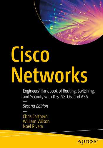
Unshielded twisted pair (UTP): This type of cabling (see Figure 2-2) is one of the most widely used types of copper cabling in computer networks today. UTP cable is relatively cheap, but it does not offer support for electrical interference protection. Bandwidth is also limited when compared to other types of cables.
Example of unshielded twisted pair cable. (Photo copyright: P B | Dreamstime.com)
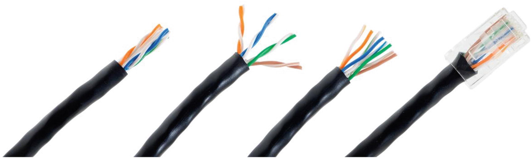
Shielded twisted pair (STP): This type of cabling (see Figure 2-3) is used in networks where faster data rates are needed. STP cable is similar to UTP cable, with the exception that it has extra metal shield wrapping around the pairs to help protect from EMI. The conductors can be shielded individually or as a group.
Shielded twisted pair cable. (Photo copyright: Sergio Bertino | Dreamstime.com)
Twisted Pair Category Ratings
Category | Maximum Data Rate | Applications Used |
|---|---|---|
CAT 1 | <1 Mbps | Analog voice (POTS), basic rate ISDN |
CAT 2 | 4 Mbps | Token ring networks |
CAT 3 | 16 Mbps | Voice and data and basic telephone service |
CAT 4 | 20 Mbps | Used for 16 Mbps token ring |
CAT 5 | 100 Mbps–1 Gbps | 10BASE-T, 100BASE-T (Fast Ethernet), GigE, FDDI, 155 Mbps ATM |
CAT 5E | 1 Gbps | FDDI, ATM |
CAT 6 | 1 Gbps | Broadband applications |
CAT 7 | 10–100 Gbps | Data center design |
CAT 8 | Emerging technology | Details to be released later |
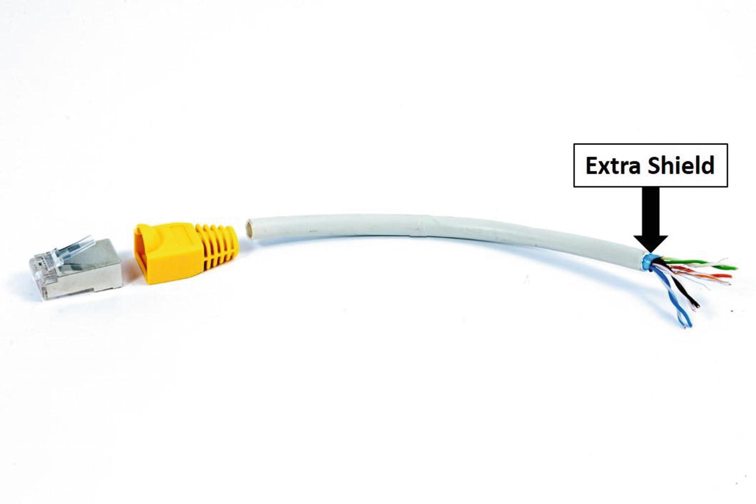
Coaxial Cable
Coaxial cable. (Photo copyright: Ra3rn | Dreamstime.com)
Fiber-Optic Cabling
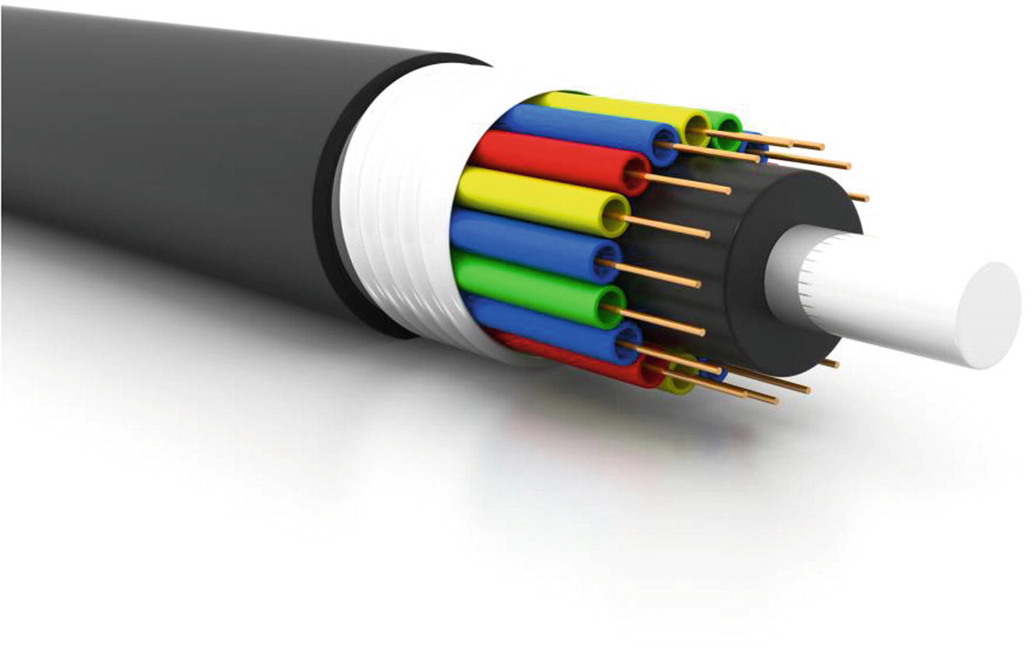
Fiber-optic cable. (Photo copyright: Bluebay2014 | Dreamstime.com)
Single-mode fiber : These cables only carry a single beam of light. This makes SM fiber more reliable than MM fiber, and it can support longer distances and more bandwidth. SM cable can transmit longer due to the propagation mode, in which the smaller angle of the beam can travel farther before it hits the edge of the core. The bulk cost of SM cabling is less expensive than MM cabling.
Multi-mode fiber : MM cabling is used for shorter distances. There are multiple beams of light, hence the name multi-mode fiber. MM fiber requires less precise light sources but travels shorter distances than SM fiber; thus, the cable supports lower speeds than SM fiber. MM fiber can support data rates up to 40 Gbps and can support distances up to 860 meters. The distances supported depend on the type of cable. For instance, OM1 fiber can support up to 275 meters at 1 Gb and 33 meters at 10 Gb. OM2 can support up to 550 meters at 1 Gb and 82 meters at 10 Gb. OM3 can support up to 860 meters at 1 Gb, 300 meters at 10 Gb, and 100 meters at 40 Gb. OM4 can support up to 860 meters at 1 Gb, 400 meters at 10 Gb, and 100 meters at 40 Gb.
Fiber-Optic Transmission Rates
Leased lines are more reliable because of higher-grade hardware and because they do not suffer from electrical interference.
Providers monitor your lines, and problems are identified sooner.
Leased lines usually include service-level agreements (SLAs) and service-level guarantees (SLGs) that contain requirements for uptime. For example, an SLA may state that within 2 hours of identifying a problem, the provider will have your communication lines back online.
Wireless Communication
Wireless networks have become the norm today. Even though many networks are wireless, wireless controllers need physical connectivity at their backbone. It is very common these days to sit in a coffee shop and connect to the Wi-Fi network. In fact, most places today offer wireless networks including airplanes. Wireless communication happens when signals are transmitted and received using antennas, microwave stations, infrared light, and satellites. Data is transmitted through the air in wireless networks. Most companies today offer wireless corporate networks to include bring your own devices to connect to the network. We will discuss wireless network configuration in Chapter 20.
Ethernet
Ethernet is a local area network architecture developed by the Xerox Corporation. The Ethernet specification is the basis of the IEEE 802.3 standard, which specifies physical and data link layers. Fast Ethernet and Gigabit Ethernet support data rates of 100 Mbps up to 1 gigabit. Ethernet is the most widely used network standard in the world. Typically, Ethernet is used to support local network deployments, but distances supported by the Ethernet have increased by kilometers.
Duplex
Full duplex: Both systems can communicate with one another simultaneously. An example of this would be an instant messenger or cellphone. Both systems can send messages and speak at the same time, as well as be seen and heard simultaneously.
Two-way radios can be designed to transmit on one frequency and receive on another, making it a full-duplex system. This is referred to as frequency division duplex. Full-duplex connections via the Ethernet use two physical pairs of twisted cable: one pair is used to receive data and the other to transmit data for simultaneous communication.
Half duplex: One system can communicate with the other only when the other is not communicating. Communication takes place one direction at a time and cannot occur simultaneously. An example of this is a push-to-talk radio similar to Sprint mobile phones or walkie-talkies. When one person wants to speak, they push the talk button, which allows the device to transmit but does not allow it to receive. If they would like the receiver to be on, then they must release the talk button to listen to the other person.
Simplex: Systems that are not duplex are simplex, which means that only one device can transmit while the others listen. Examples include baby monitors, video monitoring, microphones, radio, televisions, and public announcement systems.
The cable is collision-free and doubles the data capacity on the connection.
Time is not wasted because no frames need to be retransmitted since there are no collisions.
End units do not have to wait for each other to finish transmitting, as sending and receiving data are split between different twisted pairs.
The data capacity is doubled and increased due to the fact that sending and receiving traffic are separated. The following text displays the duplex being set on a router:
Time Division Duplexing
Time division duplexing uses time division to break up transmit and receive signals. It emulates full-duplex communication on half-duplex communication links. Time division duplexing is asymmetric on receive and transmit data rates. The rates of each can be changed dynamically if the amount of data is increased or decreased for receiving or transmitting. Examples include DSL, TDMA, and carrier sense multiple access packet switched networks.
Frequency Division Duplexing
Frequency division duplexing operates by having the sender and receiver use different carrier frequencies. This allows an endpoint to receive and transmit data at the same time by not sending data on the same frequency that it receives data on.
It is more efficient because the communications are symmetric and simultaneous.
Bandwidth is not wasted and has less latency than that in time division duplexing.
The communications do not interfere with one another because signals are transmitted and received on different frequencies.
Autonegotiation
Imagine you need to set up a meeting with a prospective employer from Japan and you live in Alaska. You need to agree on a method of communication, and you declare that you have options such as Skype, Zoom, Microsoft Teams, FaceTime, and a cellular phone. Your employer says that they have Skype, an international cellular phone, and a landline. You agree on Skype as the preferred communication. This is similar to autonegotiation. Autonegotiation is a process of the Ethernet where two connected devices choose a common set of transmission parameters that include speed, duplex mode, and flow control. The two network devices that are connected send each other messages to share which parameters they are capable of supporting and then choose the highest-performance transmission mode that both devices support. Autonegotiation occurs at the first layer of the OSI model, the physical layer.
Autonegotiation allows devices to choose different transmission rates and duplex modes, including half duplex and full duplex. Higher speeds are always preferred, and full duplex is always preferred over half duplex based on the shared capabilities offered by each network device. Parallel detection is used when one of the connected devices does not have autonegotiation enabled or does not support it. In these cases, the device with autonegotiation enabled determines and chooses a speed that matches the device it is connected to. Full duplex cannot be assumed, which is why half duplex is always chosen. Standards for 1000BASE-T, 1000BASE-TX, and 10GBASE-T state that autonegotiation must be enabled.
In both of the preceding examples, the routers should be set to autonegotiation or duplex, and speed must be set to the same parameters for both routers to negotiate to full duplex and 100 Mbps.
Unidirectional Link Detection
Unidirectional Link Detection (UDLD) is a data link layer protocol by Cisco that works with layer 1 to monitor the status of a physical link and detect a unidirectional link. UDLD was made to complement the Spanning Tree Protocol (STP), which is used to prevent layer 2 switching loops in a network. STP creates a loop-free topology by blocking one or more ports from participating in the network. STP is covered later in the book.
UDLD detects the identities of neighbors and shuts down misconnected ports. UDLD works with autonegotiation to prevent physical and logical unidirectional connections and protocol malfunctions. A neighboring switch must have UDLD enabled on its ports to exchange protocol packets. Each device sends UDLD protocol packets that have the device/port ID.
An echo of the switch should be received on the port that sent out the UDLD protocol packets, allowing the switch to receive packets with its device ID. If a port does not receive a UDLD packet for a specified duration, the switch considers the link unidirectional. After the link is labeled as unidirectional, the port is disabled until it is manually reenabled or until the timeout expires.
Common Issues
This section focuses on some of the issues that you may encounter when dealing with layer 1, including duplex mismatches and poorly made cables and bad connectors.
Duplex Mismatch
Duplex mismatches can occur when network devices are manually set to full duplex while the other is set to half duplex or autonegotiation fails. Duplex mismatches can be difficult to diagnose if the network is sending and receiving simple traffic. If your network is bogged down or running slower than usual, make sure that all of your connections are set or have negotiated to full duplex.
Duplex mismatch can also occur when one device is set to autonegotiation while the other is set to full duplex. The network device with autonegotiation set can set the speed appropriately, but it cannot determine the correct duplex mode. Your network device will also let you know in its log messages if there is a duplex mismatch. Most manufacturers of Ethernet equipment recommend enabling autonegotiation on your network devices.
Even if there is a duplex mismatch, traffic will still flow over the connection. For this reason, simple packets such as a ping cannot detect duplex mismatches. If an application that sends a large amount of data is being used, the network speed will slow down to very low speeds. The side of the link that is set to full duplex can send and receive data simultaneously, but the side set to half duplex can only send traffic when it is not receiving traffic. The side that is set to half duplex forces the TCP to resend packets that have not been acknowledged, which forces the network to function poorly.
Bad Connector Terminations
It is extremely important to test cable terminations; otherwise, performance will degrade. You will incur noise and loss of the signal if connectors are bad or part of the cable is bad. Use cable testers to verify that cables were made correctly and use signal testers to test for loss across the cable. Broken fibers are very common issues when dealing with physical cable issues. Be sure your cable lengths do not exceed the supported length of the technology. Easy ways to troubleshoot bad cables are to swap out suspected bad cables with known good cables.
Summary
Remember when thinking of physical media, it is easy to represent the lines of communication as a highway to transport data from one point to another. The type of signal representing data as bits depends on the type of medium used. When using fiber, the signals are patterns of light; when using copper cable media, the signals are patterns of electrical pulses; and for wireless media, the signals are patterns of radio waves.