This chapter covers WLANs and WLAN standards, the basic components of the Cisco wireless network architecture, how to install and configure access points, wireless controller installation and configuration, wireless security, and WLAN threats and vulnerabilities. We will also cover configuration and monitoring with Cisco Prime Infrastructure and include integration with Cisco Identity Services Engine (ISE).
Wireless LANs (WLANs)
In today's networks, wireless communication is the norm, and we must account for this as network engineers. Most wireless networks consist of access points (APs) and wireless LAN controllers (WLCs). We will discuss the configuration of these devices but also will include using ISE and Prime Infrastructure to manage the network. An autonomous AP can be used without a wireless LAN controller, but a lightweight AP requires a WLC to be paired with to function. WLCs are the central piece of a wireless network configuration and deployment. The WLC defines the IP configuration and security settings of the network. APs are normally connected via wire to a switch and receive their configuration from the WLC. At bootup, an AP attempts to locate a controller and register with it. Once the AP is registered with the controller, it builds a Control and Provisioning of Wireless Access Points (CAPWARP) tunnel which is used to transport client traffic and traffic from the AP to the WLC.
Wireless Standards
802.11a: This standard in an extension to 802.11 that provides 54 Mbps transmission in the 5 GHz band using the orthogonal frequency division multiplexing encoding scheme.
802.11b: This standard in an extension to 802.11 that provides 11 Mbps transmission in the 2.4 GHz band using DSSS.
802.11g: This standard is an extension to 802.11 that provides 54 Mbps transmission as compared to 11 Mbps with the 802.11b standard.
802.11i: This standard in an extension to 802.11 that provides security features, such as encryption and integrity.
Wireless Components
This section discusses the components of a WLAN. The devices include APs and controllers. Switches are also considered a component that is integrated into the WLAN via a physical connection between the AP and the switch.
Wireless Access Points
Access points are one of the main components of a WLAN. Your home router is considered an access point that allows access to the Internet. APs use an 802.11 standard modulation technique and operate within a frequency spectrum. Users connect to APs, and many authenticate users to the WLAN. There are different types of APs, including single and multiple radios.
Wireless Controllers/Switches
Wireless network diagram
Installing a WLAN
This section discusses the steps and considerations that need to take place when installing and setting up a wireless LAN.
Wireless Site Survey
Unless your installation takes place in an office with a few people in it, a site survey should be conducted to determine the best areas to place your access points for the best coverage possible. During the site survey, an AP and a client device are used as you move to different locations to find the most optimal location for the AP. Without a site survey or a well-planned survey, WLANs will have inadequate coverage, and the office will suffer from low performance in some locations. The time that it takes to complete the site survey will vary by the size of the office space. It is easier to complete the survey in buildings that have similar layouts on each floor. It is optimal to place the APs in the same location on each floor.
Choose tools: Various tools are used to complete the site survey, including signal meters, test APs, and spectrum analyzers to perform signal interference testing and coverage testing.
Review floor plans: Floor plans of the building should be reviewed to identify optimal locations for access points and to review the results of signal testing.
Review the requirements: The installation requirements should be documented, and reviews should be held with the customer to go over items such as the size of the facility, the number of users that need to be supported by the network, and whether continuous coverage is needed throughout the facility. Also, the budget should be considered. These types of requirements drive what types of equipment you select for the installation.
Perform a facility walk-through: You should walk through the facility with the identified options for AP placement on your map. You should test by mounting your AP and antennas and walk around the entire facility with a laptop to record testing data. Cisco makes an Aironet Desktop Utility to view the quality of the AP signal, the strength of the signal, the percentage of packet retries, the link speed, the overall link quality, and the signal-to-noise ratio (SNR). The SNR can be high, even though you have a strong signal, but many packets may be resent due to the high noise. The packet retry percentage, or the number of times packets are resent, should be under 10% in all locations tested. This process should be completed each time you move the AP to another location. During the site survey, close all doors to get an accurate test of the signal quality. Sources of interference should be noted, including air conditioning units, power distribution closets, and elevators.
Complete a report: A site survey report should be completed with all the test results, including how the test was conducted and which equipment was used. Document how the WLAN can be integrated into the current network if there is a network already configured. Information on power should not be overlooked either. How will the APs be powered? Will they receive power via PoE to a switch or via a power supply? The amount of power needed to operate each AP should be accounted for.
Access Point Installation
One of the most important installations of a WLAN is the access point. As mentioned earlier in this chapter, if you use many APs, you must configure them one by one, whereas if you use a controller, the configuration can be completed by the controller for each AP. The AP should be installed clear of obstacles to increase the range of the signal. Do not place it near metal objects and furniture. Ceilings are an ideal place to mount access points so that employees cannot tamper with them. Also keep in mind weather conditions of the area. If an AP is to be installed outdoors or in the elements, make sure that it is designed to withstand such environmental factors.
Access Point Configuration
After you connect a Cisco lightweight access point (LAP), it will boot up and try to communicate through the switch to a Cisco wireless LAN controller. The switch needs to be configured with the correct access VLAN and inline power settings. The LAP will try to locate one or more controllers on the network to join. The LAP will try to build a CAPWAP tunnel with the controller and will send a CAPWAP join request. The controller will respond with a join response message. The LAP will then download its image and configuration from the WLC. After the discovery process is finished, the LAP can now be fully managed by the controller.
WLAN Controller Installation
- 1.
Power up the controller and complete initial configuration. This step involves defining the port to be used for WAN uplinks and which ports will be used for WLAN access.
- 2.
Determine if you need to support one of multiple virtual WLANs. This step involves documenting the virtual WLANs.
- 3.
Create the WLANs in the controller. This step involves configuring the controller’s access ports for the WLANs created in the previous step. Security settings can be configured during this step.
- 4.
Connect the controller to access points. The controller should be connecting to APs via the controller’s access ports.
- 5.
Configure access ports on the controller. The access ports should be configured at this step. VLANs are used if you need to logically separate WLANs.
WLAN Controller Configuration
This section focuses on the configuration of the WLAN controller using the Cisco GUI.
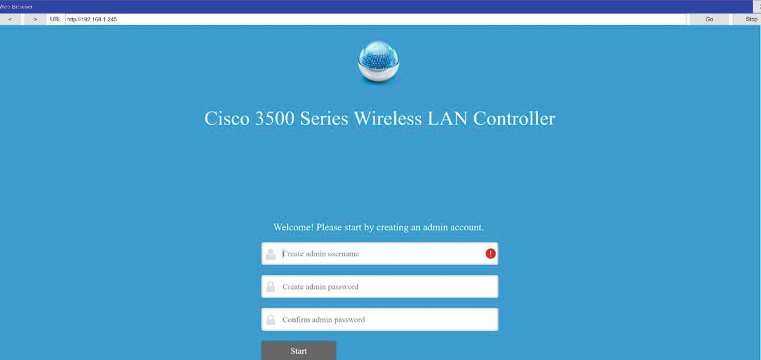
Initial Configuration of WLC via a Web Browser
Wireless controller GUI
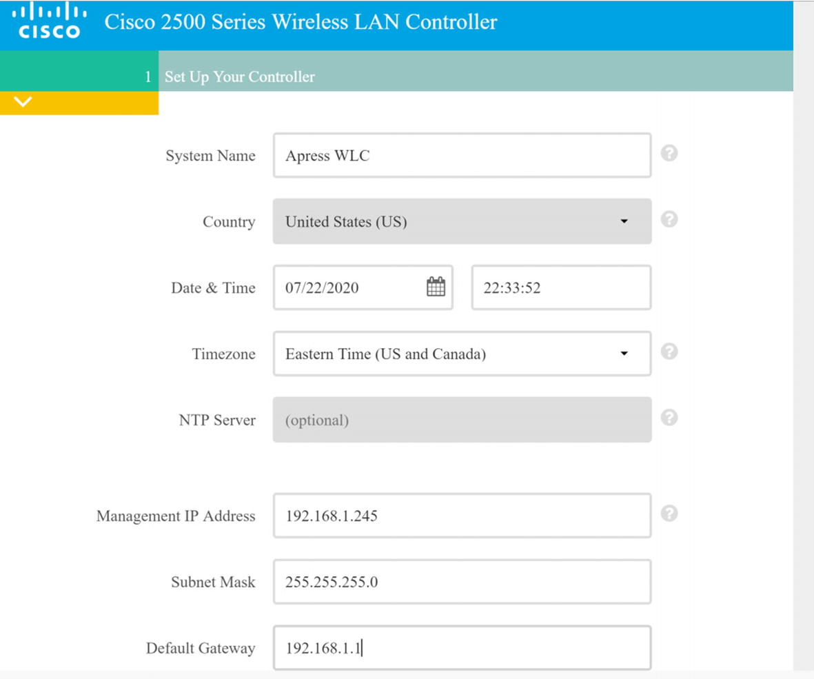
Wireless LAN Controller Configuration
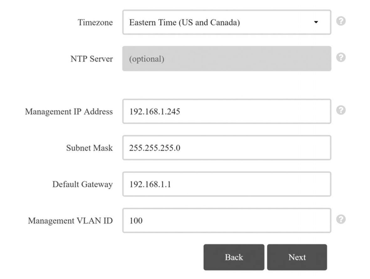
Wireless LAN Controller Configuration Continued
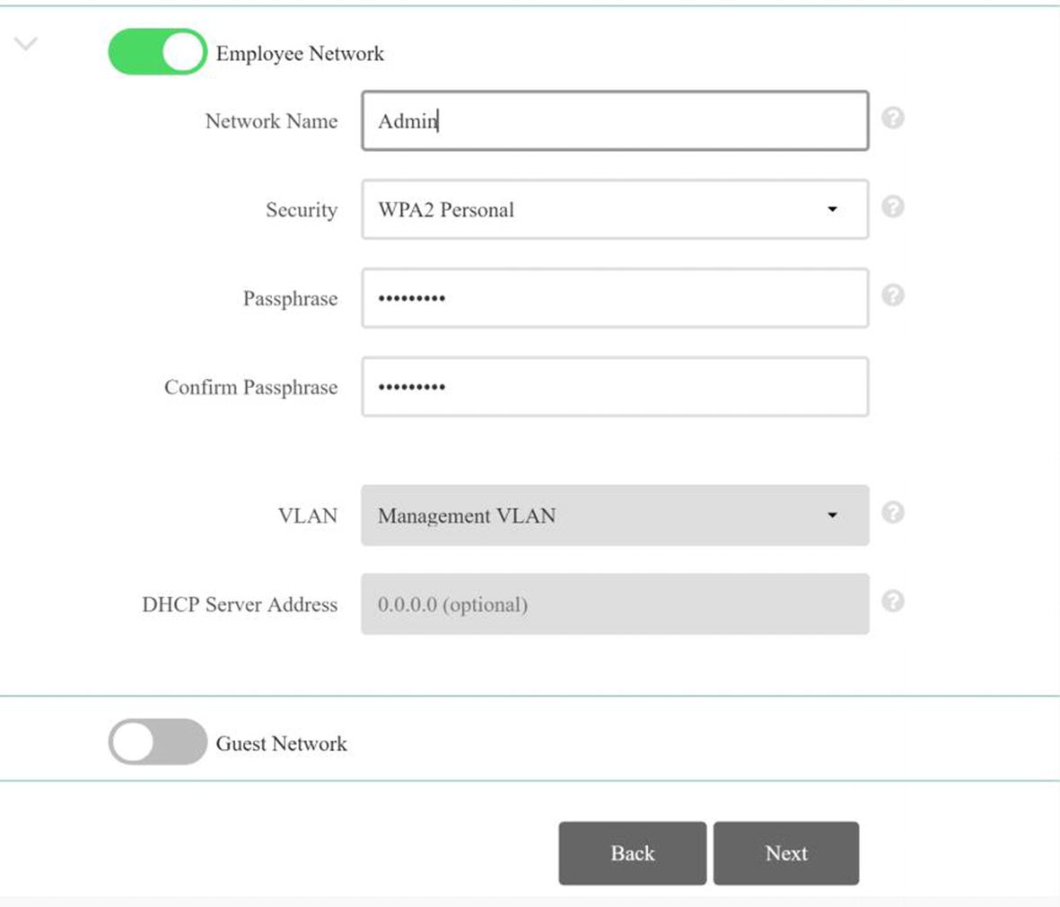
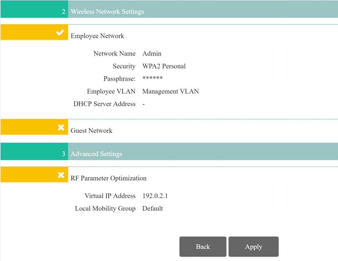
WLC network creation page
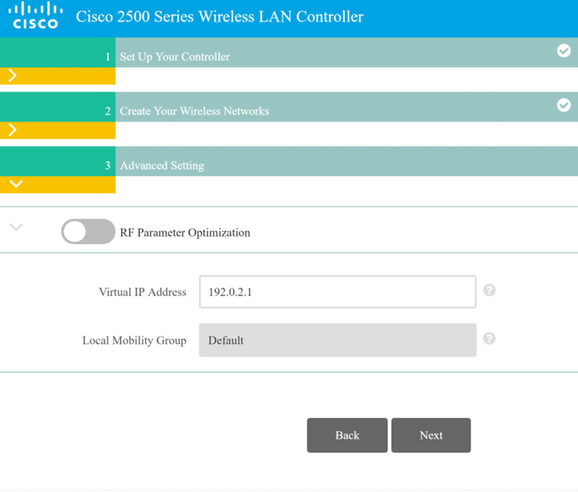
WLC RF optimization
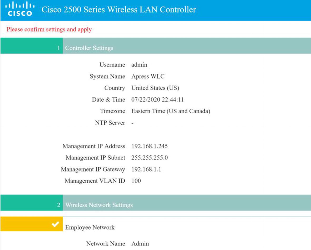
WLC summary
WLC summary continued
WLC login
WLC Monitoring
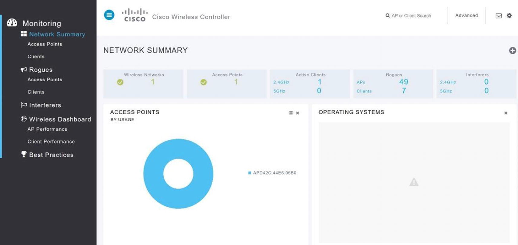
WLC network summary

WLC MONITOR summary
You can see the summary screen of the wireless controller GUI in Figure 20-11. It features information such as the controller IP address, software version, name, number of access points, current clients, and rogue access points.
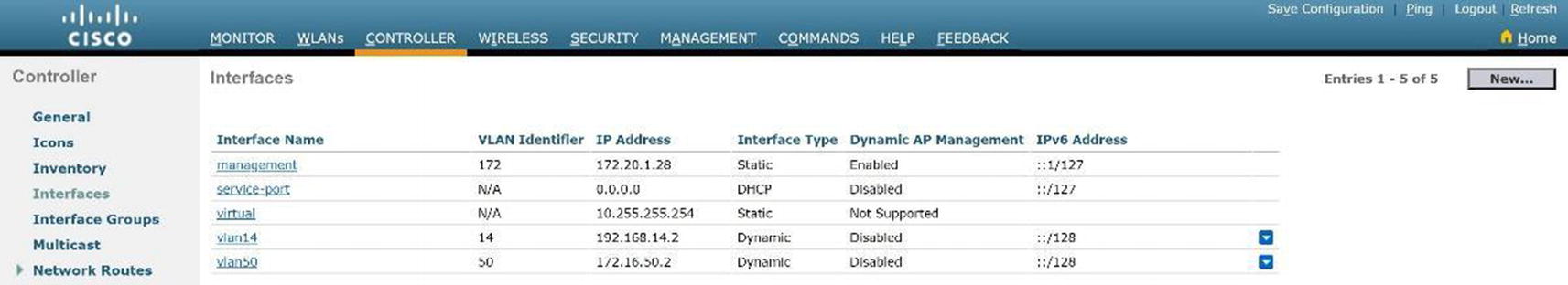
VLAN Configuration
The Interfaces option under CONTROLLER in the left menu is where we configure VLANs on the WLC. Interfaces are logical connections internal to the controller, whereas controller ports are physical connections on the WLAN.
WLC new VLAN

WLC VLAN
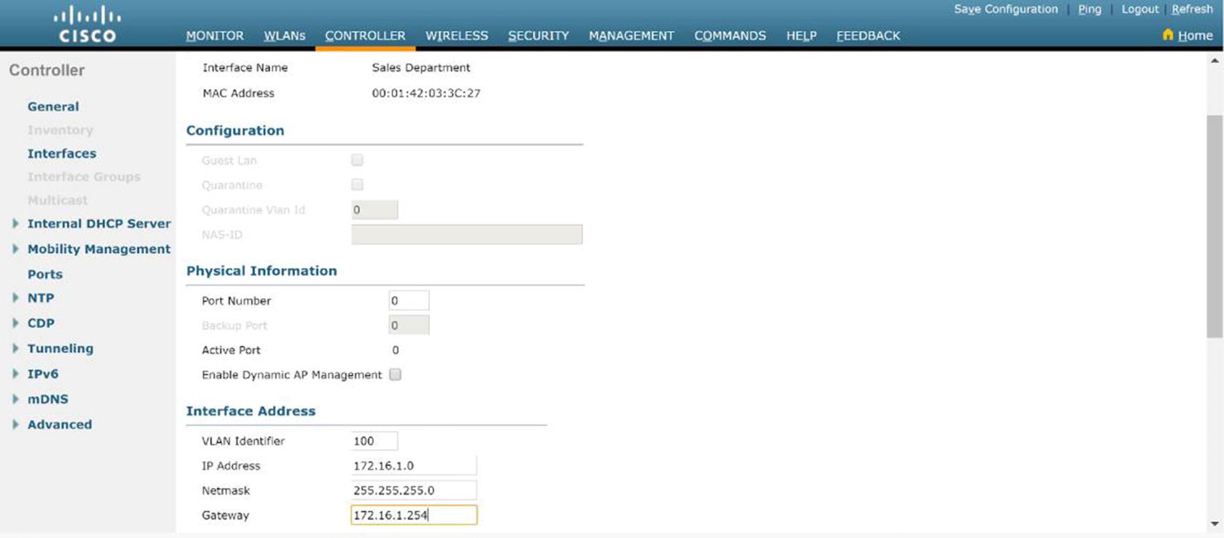
WLC VLAN configuration
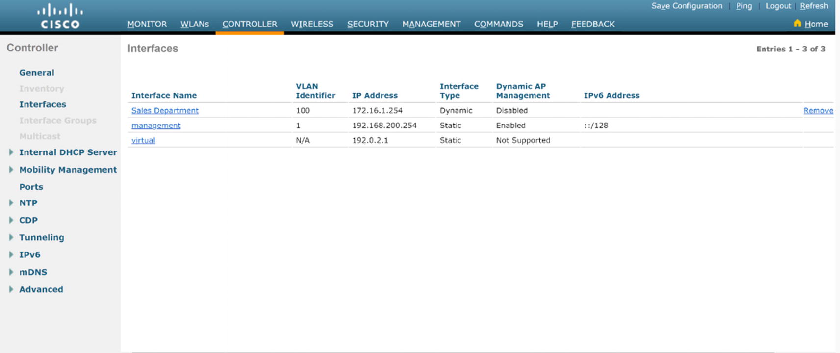
WLC VLAN summary
DHCP Configuration
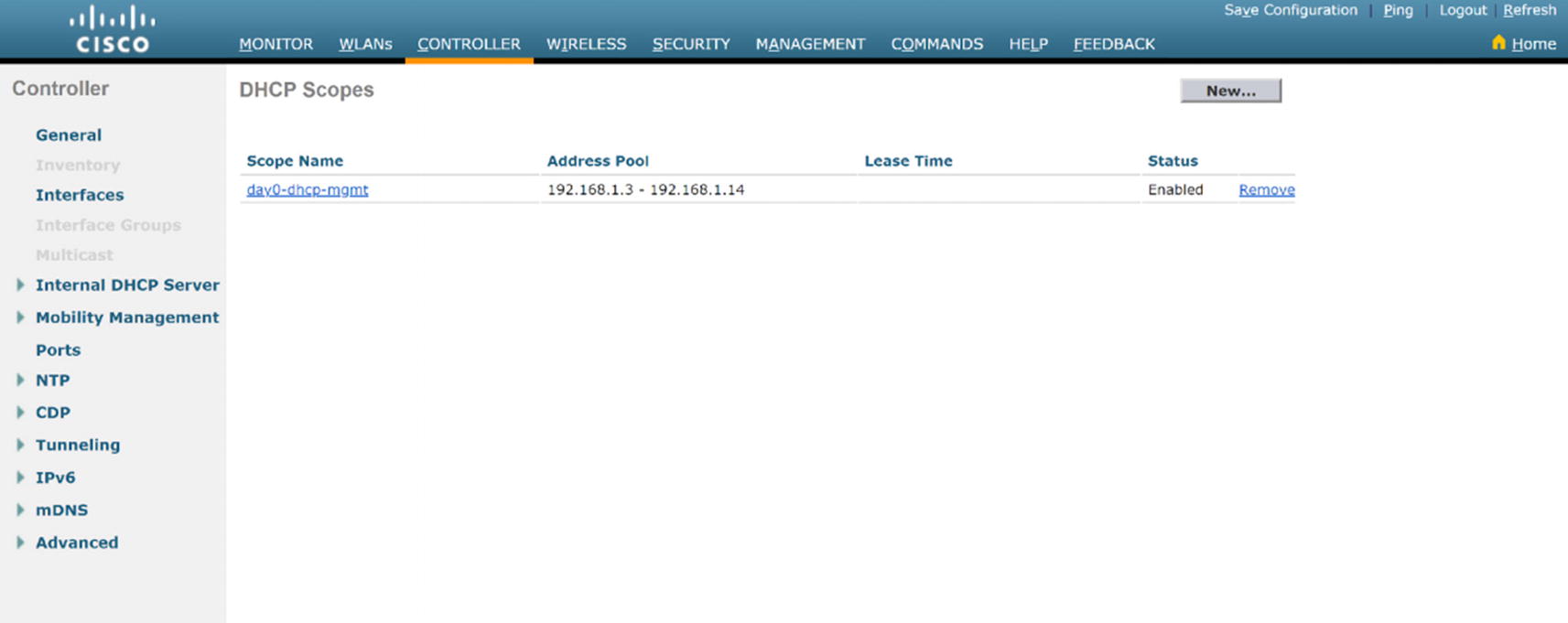
WLC DHCP summary

WLC DHCP creation
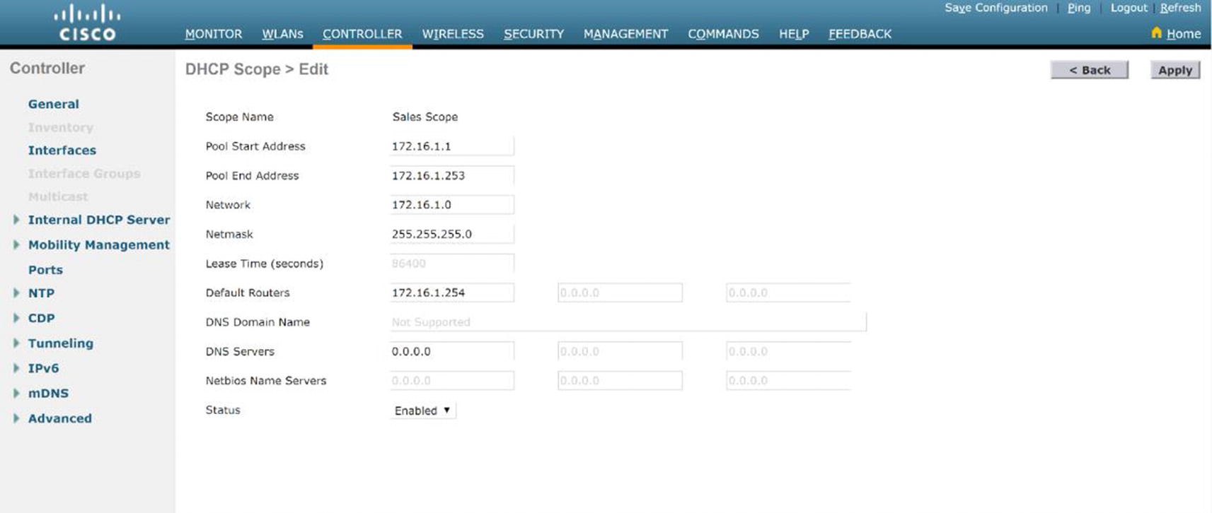
WLC DHCP configuration
Don't forget to click Apply in the upper-right menu and click Save configuration in the upper-right menu afterward.
WLAN Configuration

WLC WLAN creation

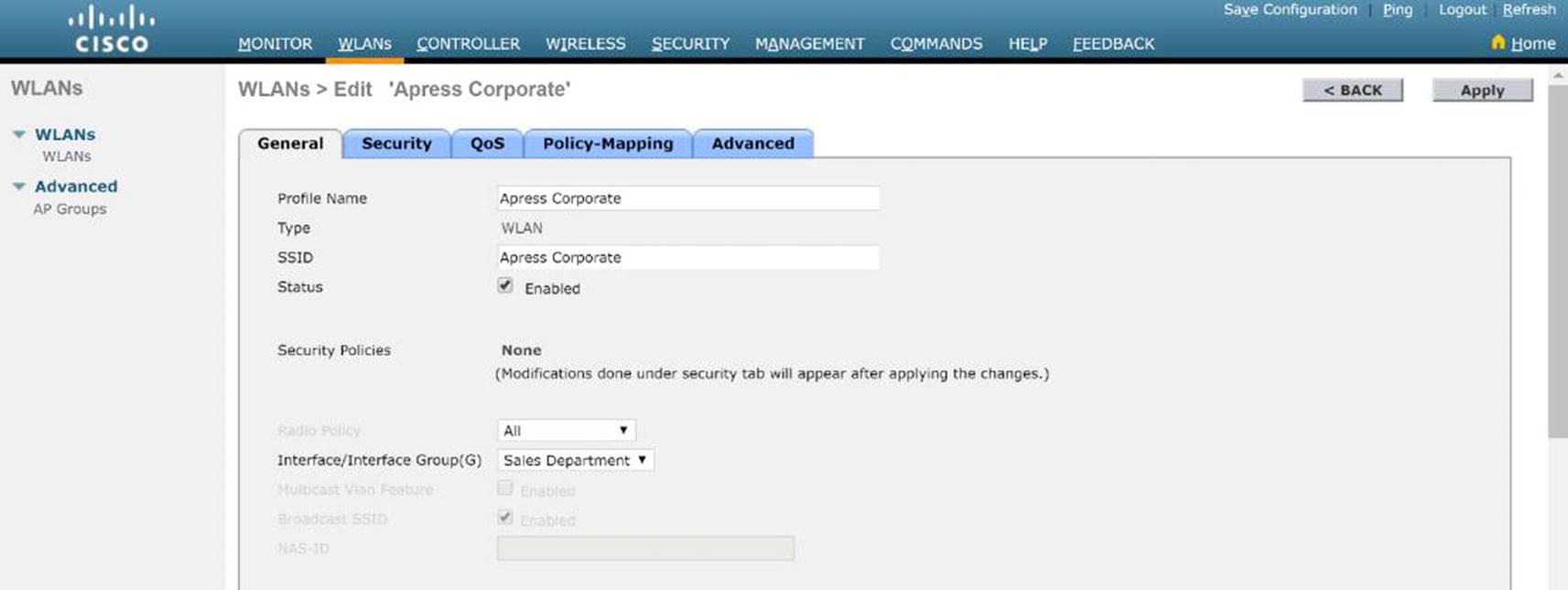
WLC WLAN configuration
WLC WLAN enabled
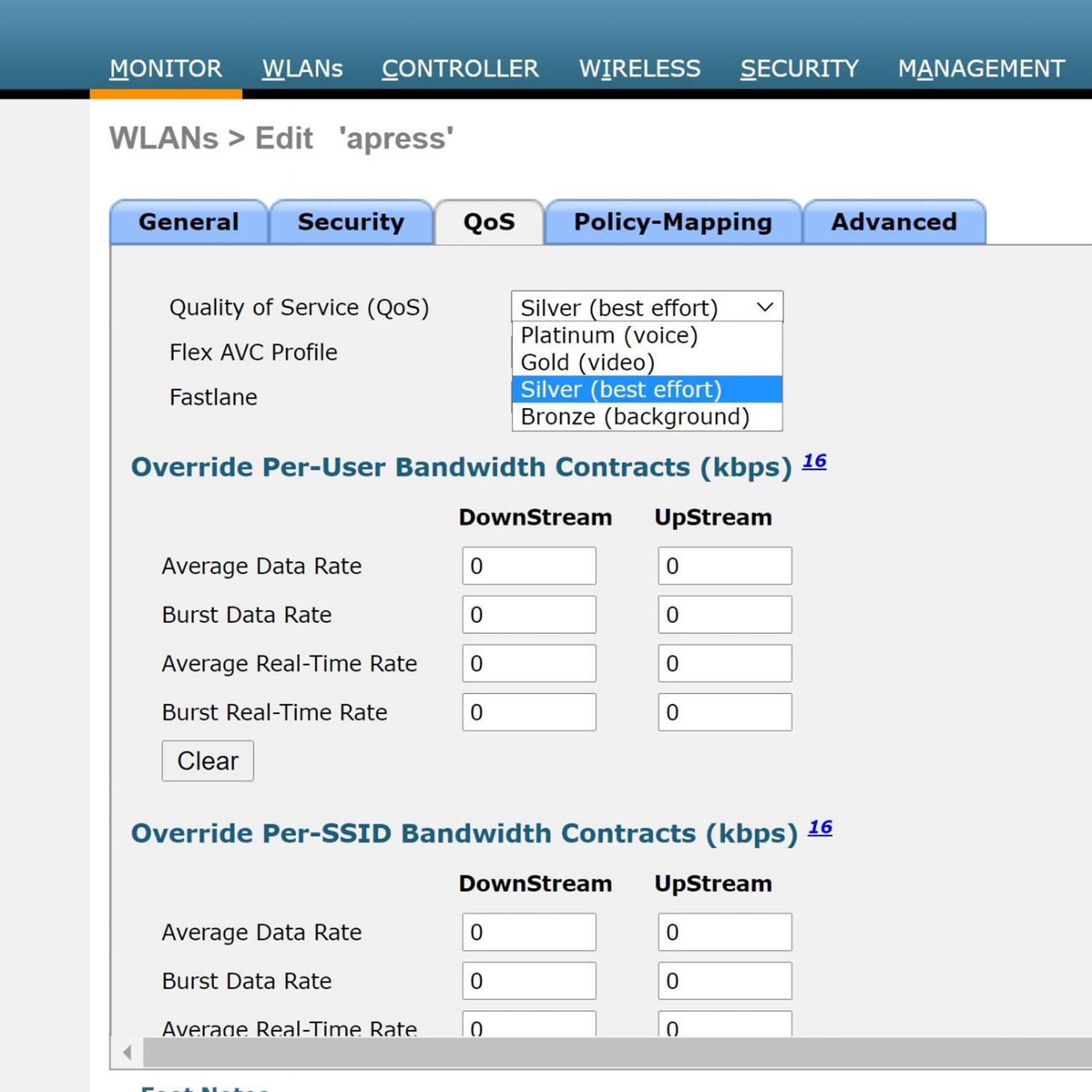
WLC QoS configuration
MANAGEMENT
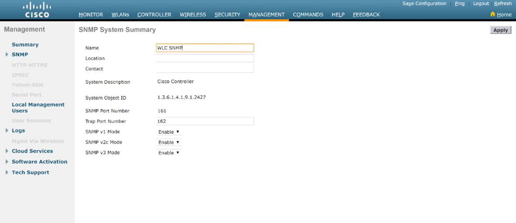
WLC SNMP configuration
Security
WLAN security is a huge concern for any network administrator. There are many threats introduced into your network when you move to wireless, which wired networks do not have to be concerned about. Also note that you still must secure the networks from the same vulnerabilities that exist in wired networks. Anyone can sniff your traffic because it is in the air. This section explores security concepts, such as the vulnerabilities that are introduced and how to mitigate the threat of an attack on your WLAN. Many WLANs today do not implement good security, which almost allows access to anyone. If you want proof, just look at some of your neighbors’ networks—they are wide open (but do not use their networks).
Encryption and Authentication
Let’s very briefly cover wired equivalent privacy (WEP), because it should not be used for encryption and any network using WEP should be considered insecure. It is important to protect your data by keeping unauthorized users out of the networks and preventing eavesdropping. Next, you learn about Wi-Fi Protected Access (WPA) and 802.1x authentication.
WPA
WPA has two versions, WPA and WPA2, which were introduced by the Wi-Fi Alliance. WPA was developed to replace WEP due to its vulnerabilities. WPA makes key cracking very unlikely because it causes automatic key changes. WPA can be used with 802.1x or pre-shared keys. WPA2 is a stronger form of encryption and is an update to WPA. WPA uses Rivest Cipher 4 (RC4), whereas WPA2 uses Advanced Encryption Standard (AES), which is one of the strongest encryption algorithms. It has not been broken to date and is used to protect government information.
802.1x
802.1x uses several authentication protocols to provide access control, including the Extensible Authentication Protocol (EAP), Extensible Authentication Protocol Transport Layer Security (EAP-TLS), Protected EAP (PEAP), Lightweight Extensible Authentication Protocol (LEAP), and EAP Flexible Authentication via Secure Tunneling (EAP-FAST). 802.1x prevents users from being allowed to pass data through a WLAN AP until they have been authenticated. Authentication is based on a supplicant or user that would like access, an authenticator or an AP that grants network access, and an authentication server that grants permission based on credentials provided by the supplicant.
Smart cards
One-time passwords
Certificates
Public key authentication
Tokens
Kerberos
The EAP process of authentication starts with a user trying to associate with an AP. The AP restricts the user from network access, and the user must provide authentication information. Next, the authentication server and user authenticate each other and agree on a key. Finally, the user is granted access to the network.
EAP-TLS uses public key cryptography, allowing the server and user to mutually authenticate each other. Digital certificates and smart cards are forms of public key cryptography. The communication between the user and server is encrypted with a TLS tunnel. WEP, WPA, or WPA2 encrypts the data after the user is authenticated. The EAP-TLS process of authentication starts with a user trying to associate with an AP. The AP restricts the user from network access, and the user must provide authentication information via a certificate. Next, the authentication server provides a certificate to the user. The user and the server authenticate each other and agree on a key and establish a secure tunnel. Finally, the user is granted access to the network.
PEAP uses a server-side authentication system similar to that used in SSL using TLS. The PEAP process of authentication starts with a user trying to associate with an AP. The AP restricts the user from network access. The user verifies the server certificate. Next, the authentication server authenticates the user by using a one-time password or some other means and agrees on a key. Finally, the user is granted access to the network. Windows passwords and usernames can be used to authenticate users also, including the authentication server communicating with Active Directory to allow user access.
LEAP provides a username and password authentication that allows users access to the network. Each time a user authenticates, a new key is generated. Every time a user moves to a new AP, a new key is created. The LEAP process of authentication starts with a user trying to associate with an AP. The AP restricts the user from network access. The user must provide login credentials to the server. Next, the authentication server and user authenticate each other and create a session key. Finally, the user is granted access to the network.
EAP-FAST uses a certificate-based authentication with a username and password via an encrypted TLS tunnel between the user and authentication server. EAP-FAST uses shared secret keys to make reassociation between the user and the AP fast. Public keys can also be used, but the AP must know the secret key for the user in advance. The EAP-FAST process of authentication starts with a user trying to associate with an AP. The AP restricts the user from network access. The user verifies the server’s credential with the shared key. Next, the authentication server and user agree on a key. Finally, the user is granted access to the network after the secure tunnel is connected.
Authentication Server
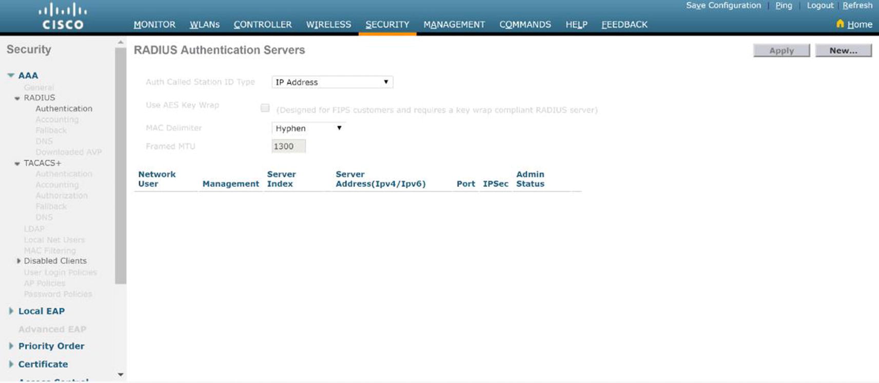
WLC RADIUS authentication server
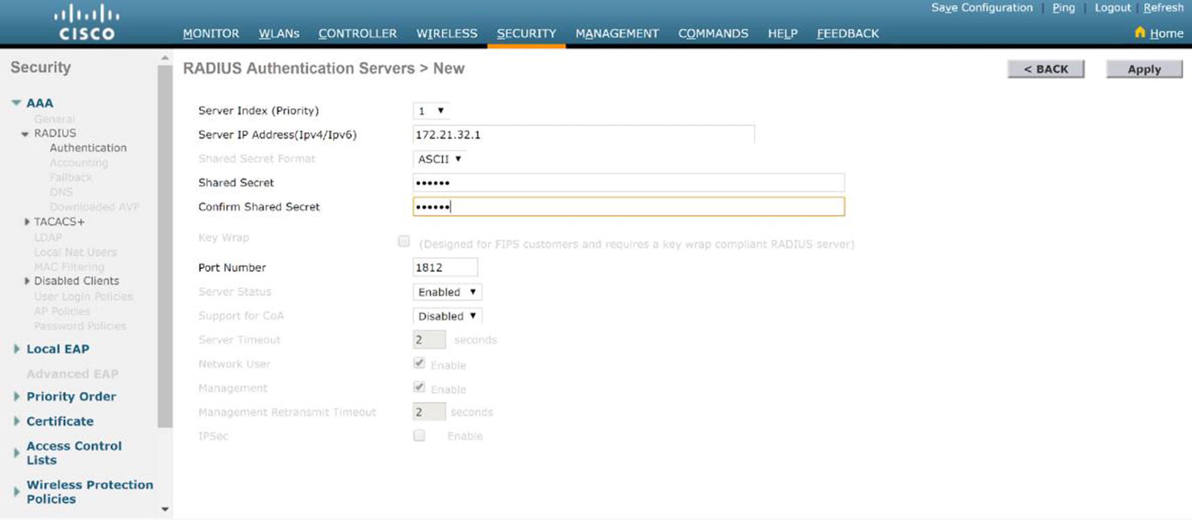
WLC RADIUS server configuration

WLC WLAN security
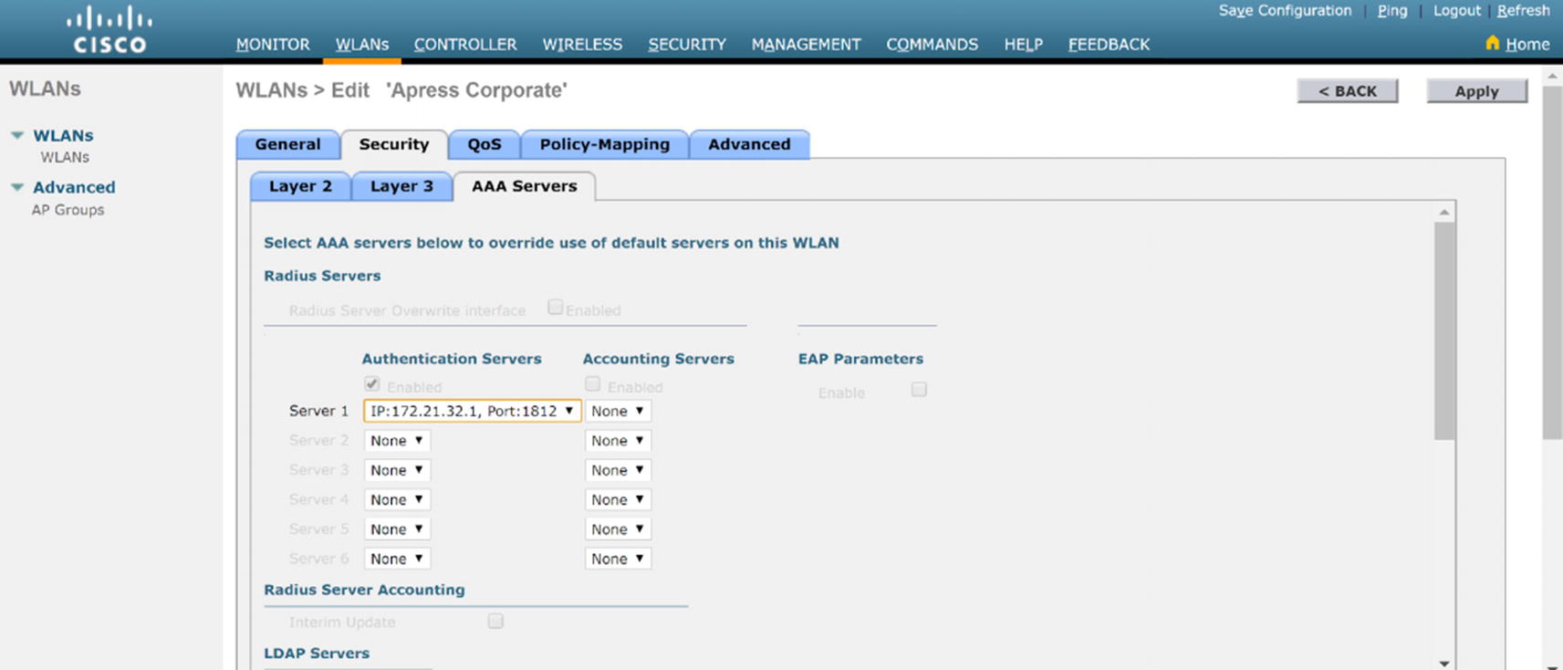
WLC WLAN security AAA configuration
Cisco ISE
Cisco ISE and WLAN
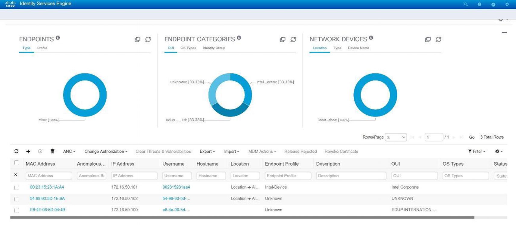
Cisco ISE GUI

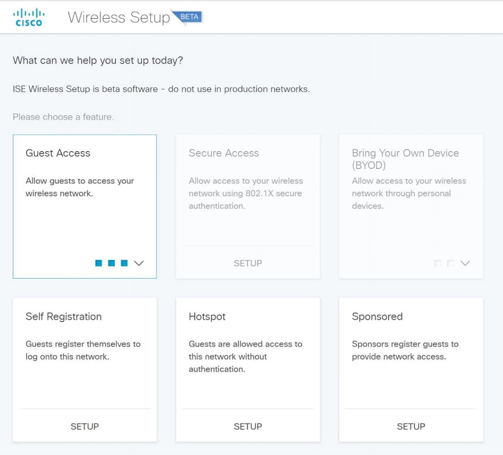
Cisco ISE wireless setup menu

Cisco ISE wireless setup
Bring Your Own Device (BYOD) : Give your employees the option to use their own devices you specify as admin or allow them to enroll in a device portal.
Guest Access: This will allow a custom portal page where a guest can register their device to create a wireless access account.
Secure Wireless with WPA2, PEAP authentication, and 802.1x: This will secure corporate users using Active Directory for authentication.
Wireless Setup Wizard
Cisco ISE wireless guest setup
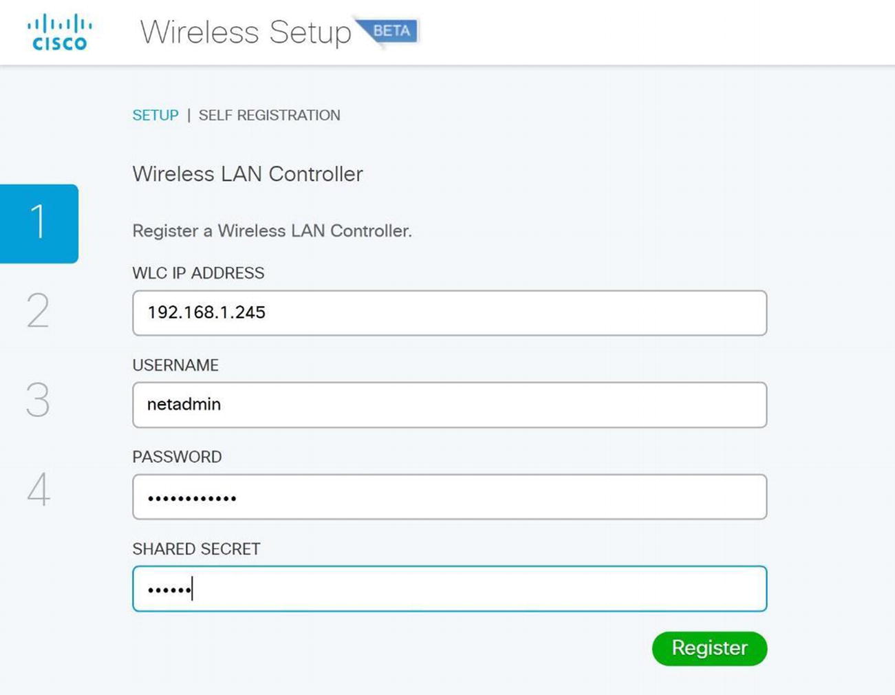
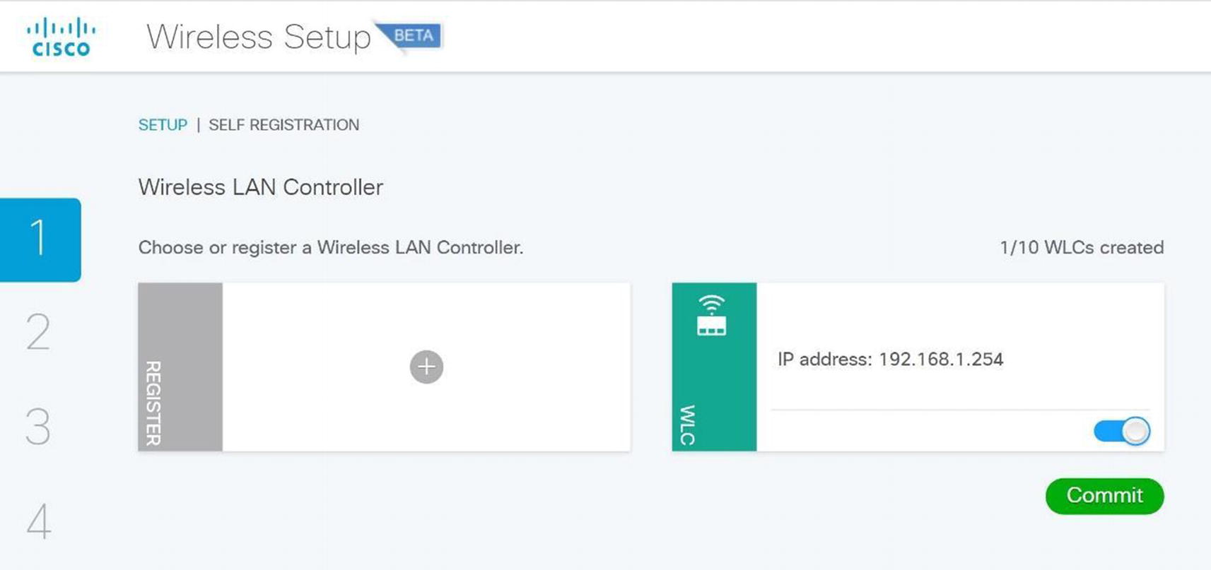
Cisco ISE WLC setup
Cisco ISE wireless guest self-registration setup
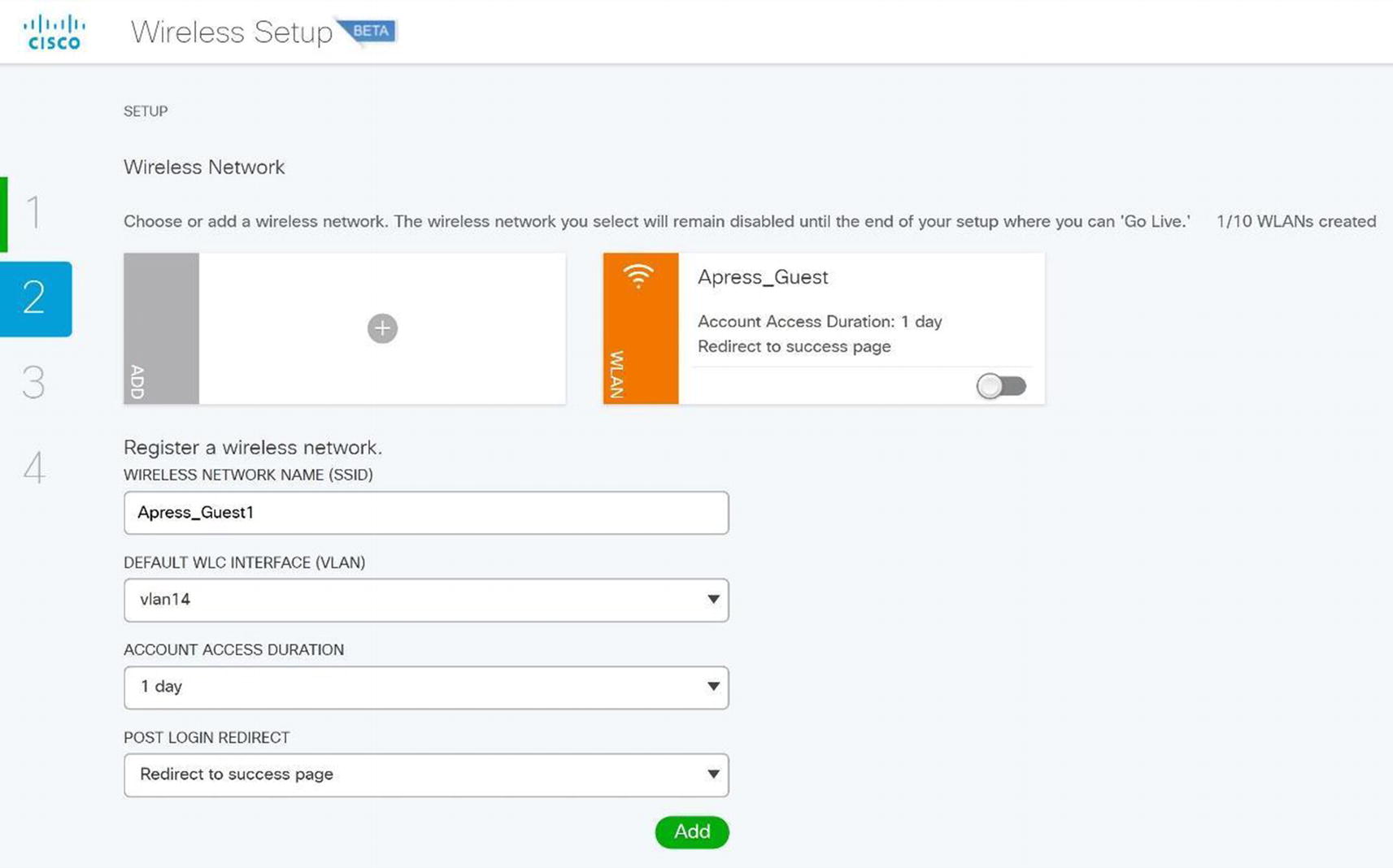
Cisco ISE wireless SSID setup
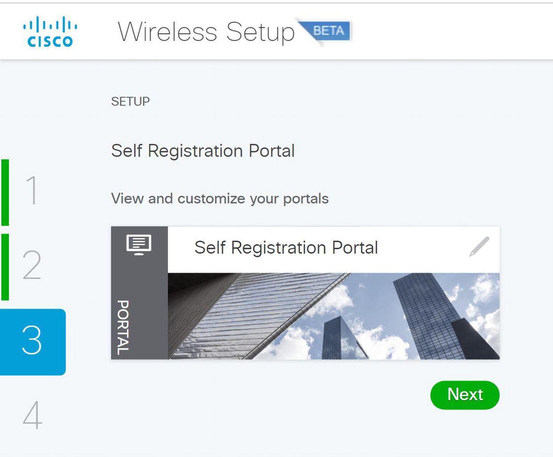
Cisco ISE wireless self-registration portal
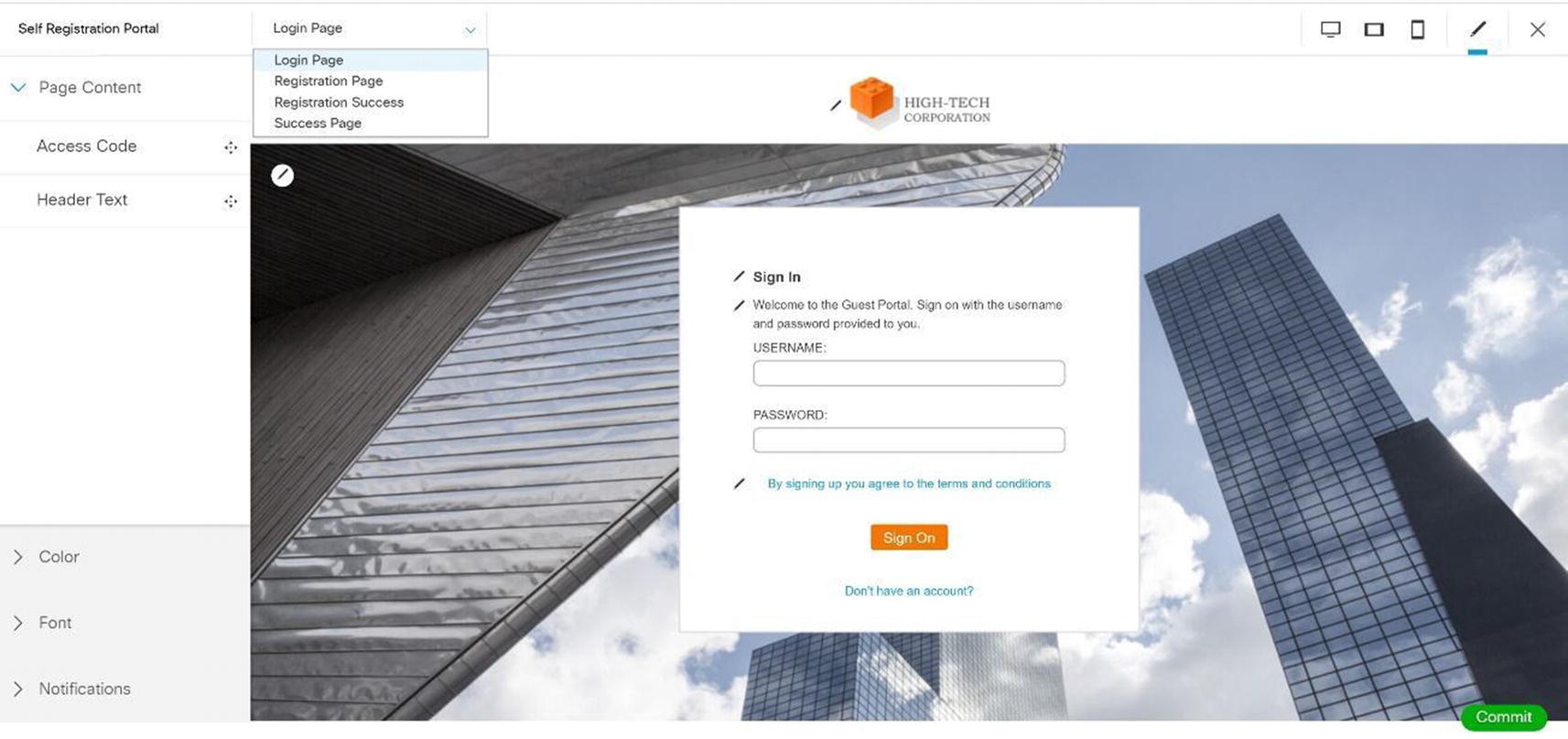
Cisco ISE wireless self-registration portal edit
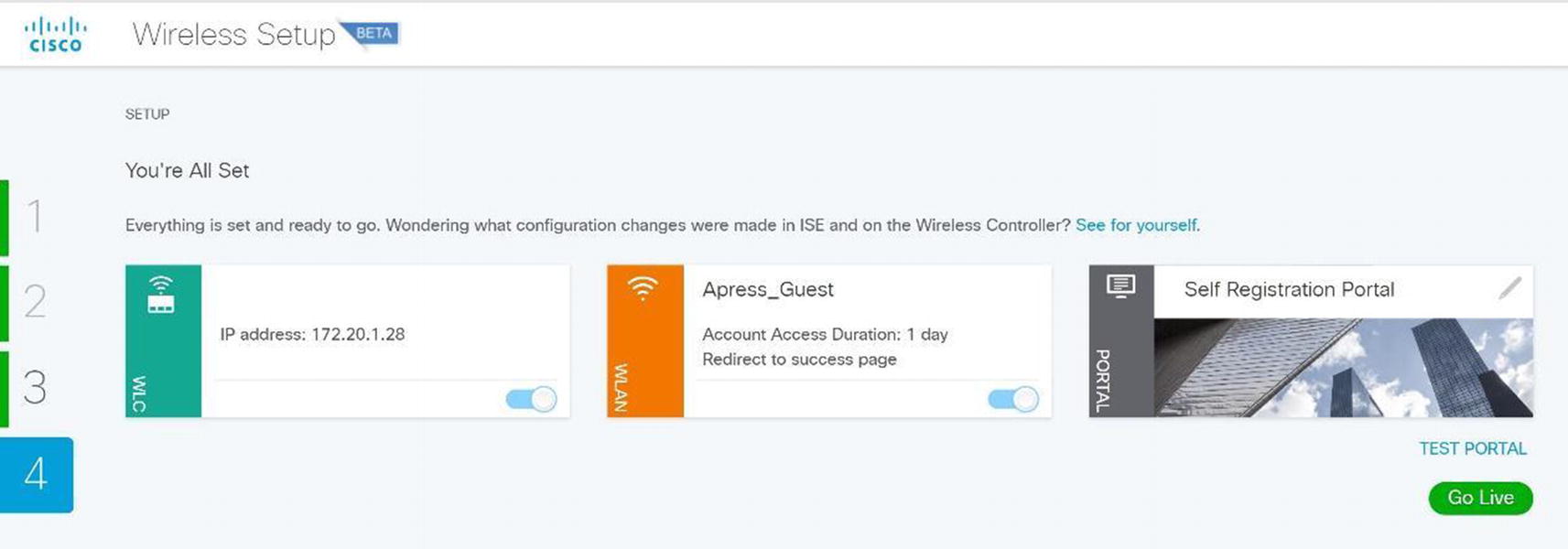
Cisco ISE wireless setup completion
Hotspot Wizard

Wireless Cisco ISE wireless hotspot setup
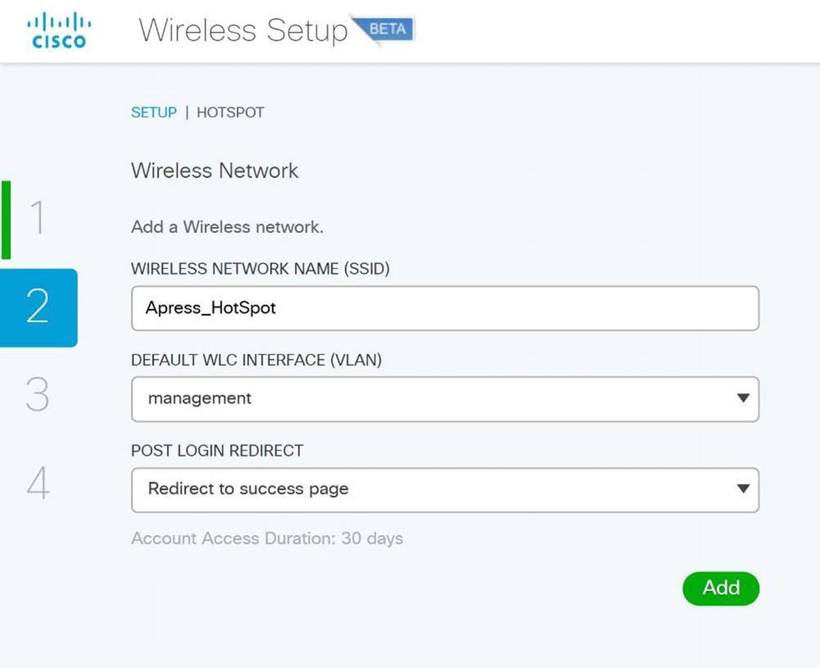
Wireless ISE wireless hotspot configuration
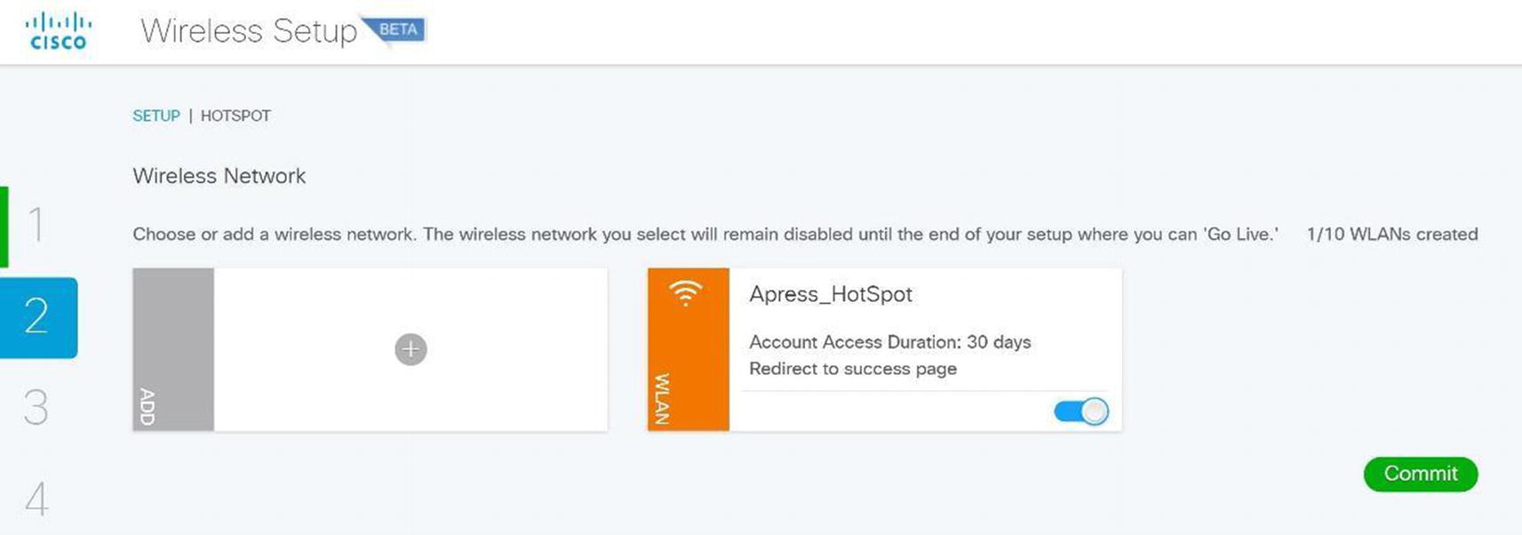
Wireless ISE wireless hotspot
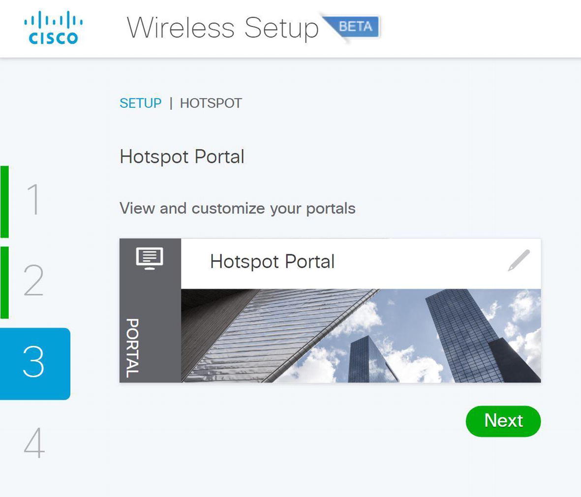
Wireless ISE wireless hotspot portal
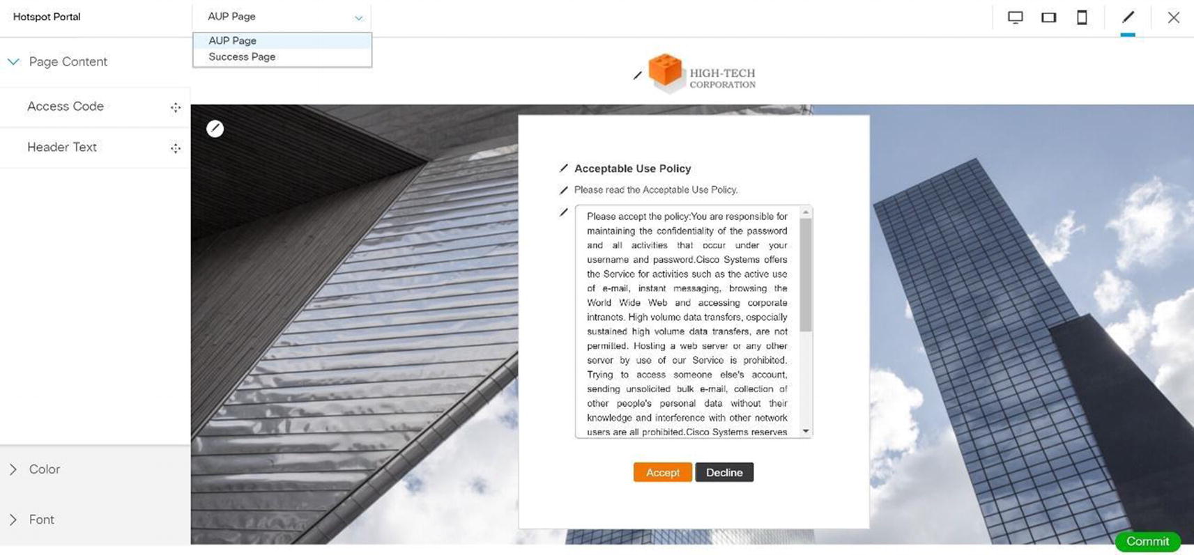
Wireless ISE wireless hotspot portal configuration

Wireless ISE wireless hotspot portal test

Wireless ISE wireless hotspot portal acceptance

Wireless ISE wireless hotspot portal connection

Wireless ISE wireless hotspot portal completion
We are now ready to go live. Click Go Live so users can use the hotspot. Figure 20-47 displays the BYOD wireless wizard.
BYOD Wizard

Wireless ISE wireless BYOD wizard
Select Single SSID.
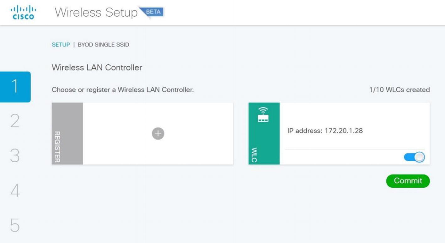
Wireless ISE wireless BYOD WLC selection
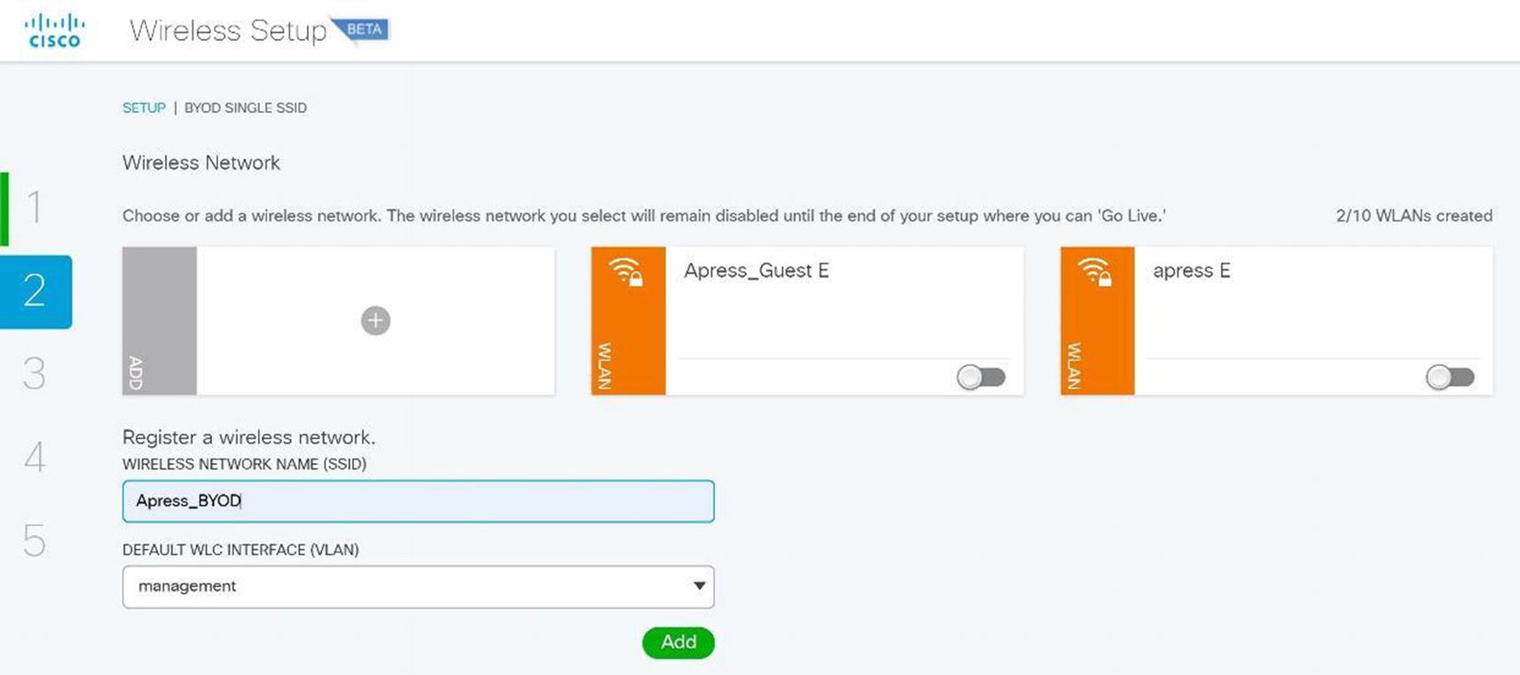
Wireless ISE wireless BYOD SSID setup
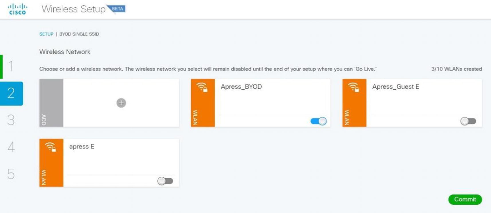
Wireless ISE wireless BYOD SSID configuration
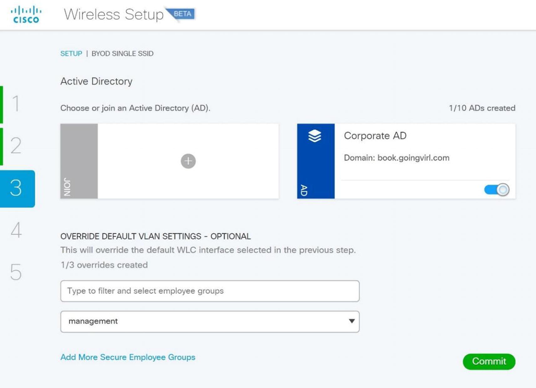
Wireless ISE wireless BYOD AD configuration
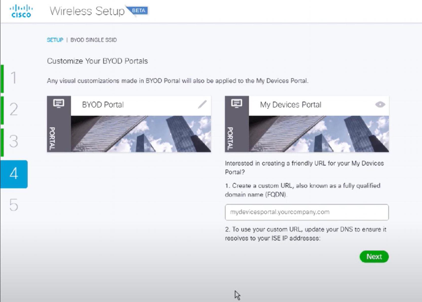
Wireless ISE wireless BYOD portal
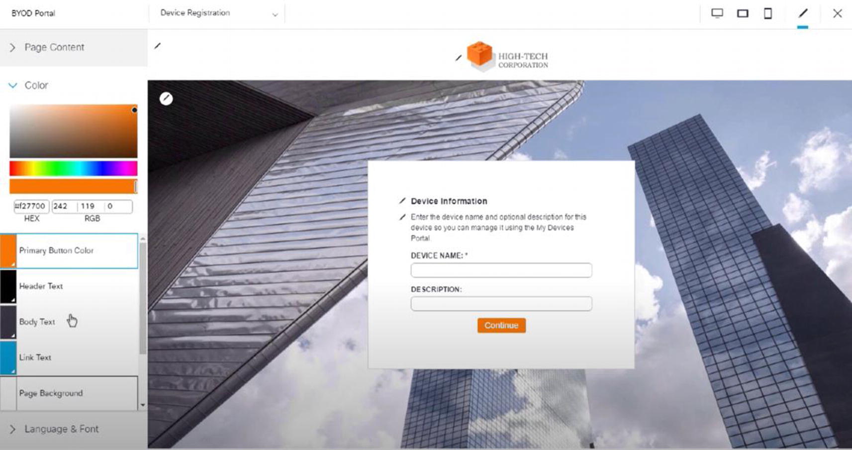
Wireless ISE wireless BYOD portal configuration
Lastly, we are ready to click Go Live and use the BYOD portal.
Cisco Prime
Cisco Prime Infrastructure has been discussed in other chapters, and we will discuss it here too as it can be used to manage wireless networks.
It allows you to track devices and display their locations using spatial maps.
It contains wireless planning tools for AP placement.
It allows you to use configuration templates to deploy WLCs and APs.
It allows you to receive alerts and has a built-in troubleshooting tool.
It allows for monitoring of the wireless network.
Detailed reports can be run.
Cisco Prime login
After logging in, you see a home page as in Figure 20-55.
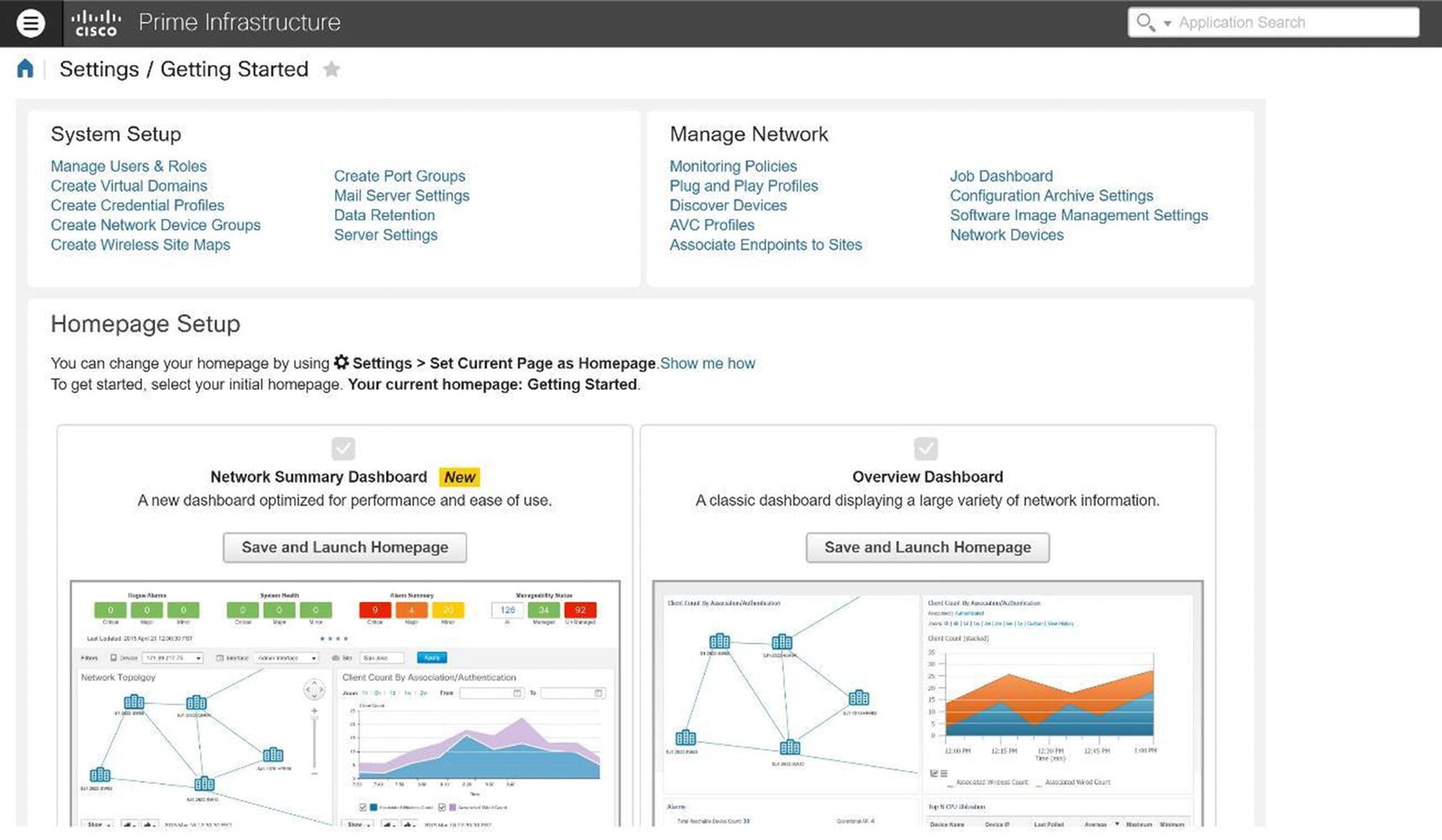
Cisco Prime home page
Dashboard: Displays dashboards of network activity or information.
Monitor: Monitoring display for troubleshooting and maintenance.
Configuration: Configuration templates are monitored and deployed.
Inventory: Manage device and software inventory.
Maps: View network architecture maps.
Services: Access mobility services.
Reports: View reports.
- Administration: Prime Infrastructure server management.
 Figure 20-56.
Cisco Prime Dashboard Overview

Cisco Prime Configuration menu
Critical: Shown with a red circle
Major: Shown with an orange triangular arrow
- Minor: Shown with a yellow triangular arrow
 Figure 20-58.
Cisco Prime alarms
Wireless Network Monitoring
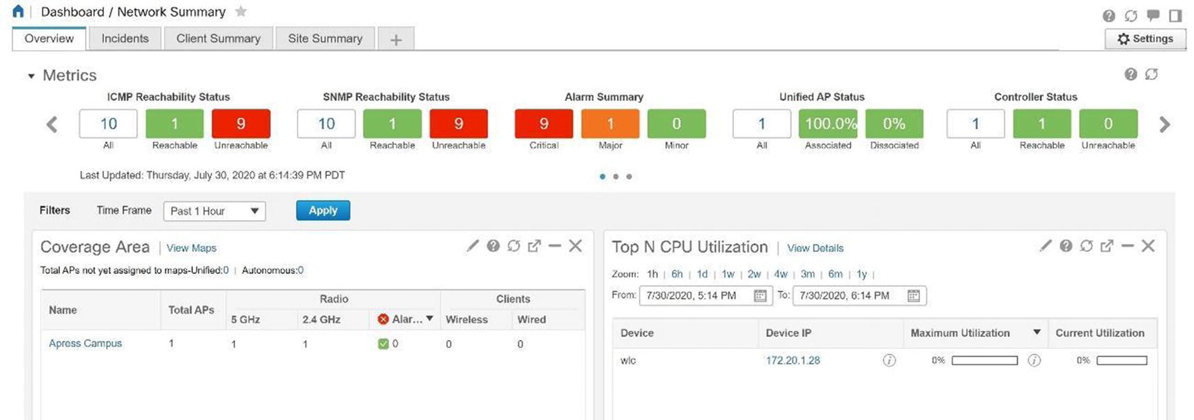
Cisco Prime network summary
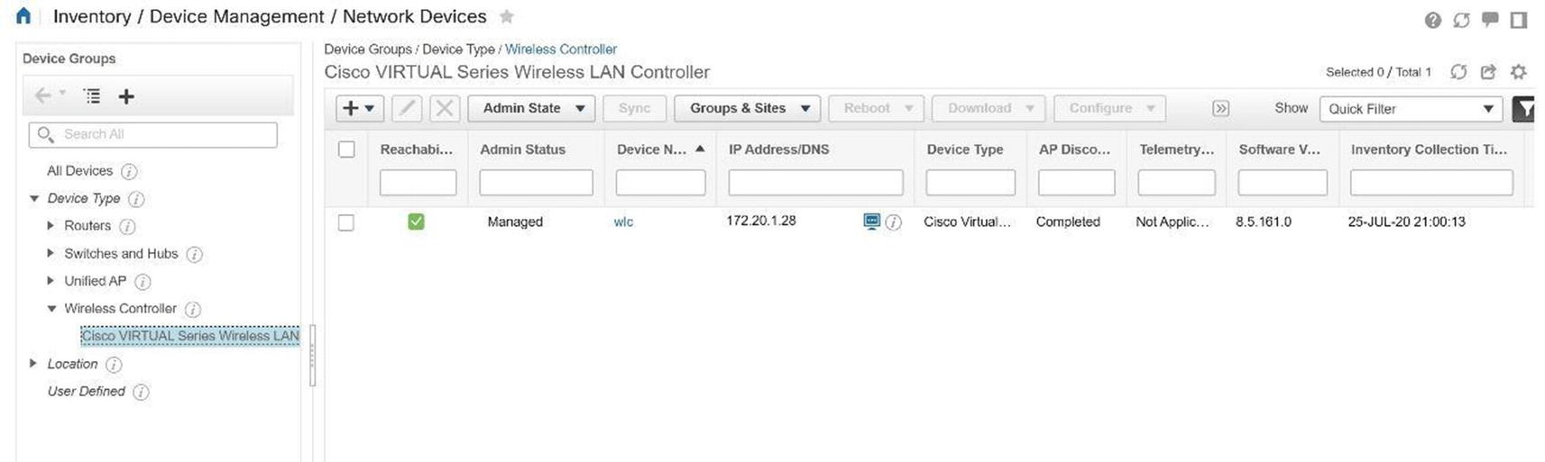
Cisco Prime network devices
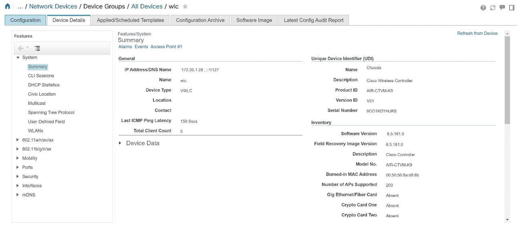
Cisco Prime WLC details
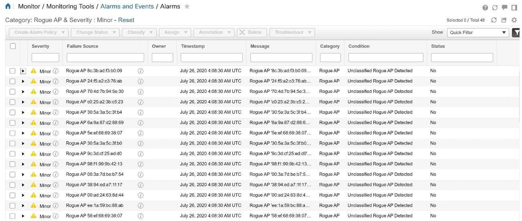
Cisco Prime rogue access point alarms

Cisco Prime rogue access point alarm details

Cisco Prime Security dashboard
Prime Infrastructure Maps
Prime allows you to have a visual representation of your wireless controllers and APs to include their location and coverage area. PI provides this visual representation with maps; data displays physical locations and predictive RF coverage. You can upload a floor plan as an image file as well. Maps can be accessed by navigating to Maps ➤ Wireless Maps ➤ Site Maps. Follow the map configuration using Figures 20-65 through Figures 20-71.
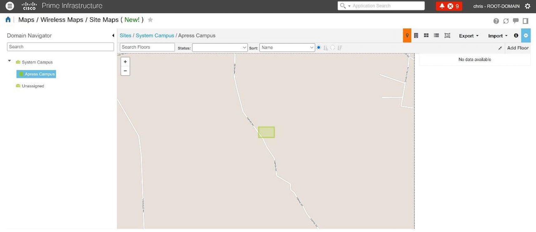
Cisco Prime site map
Cisco Prime campus map

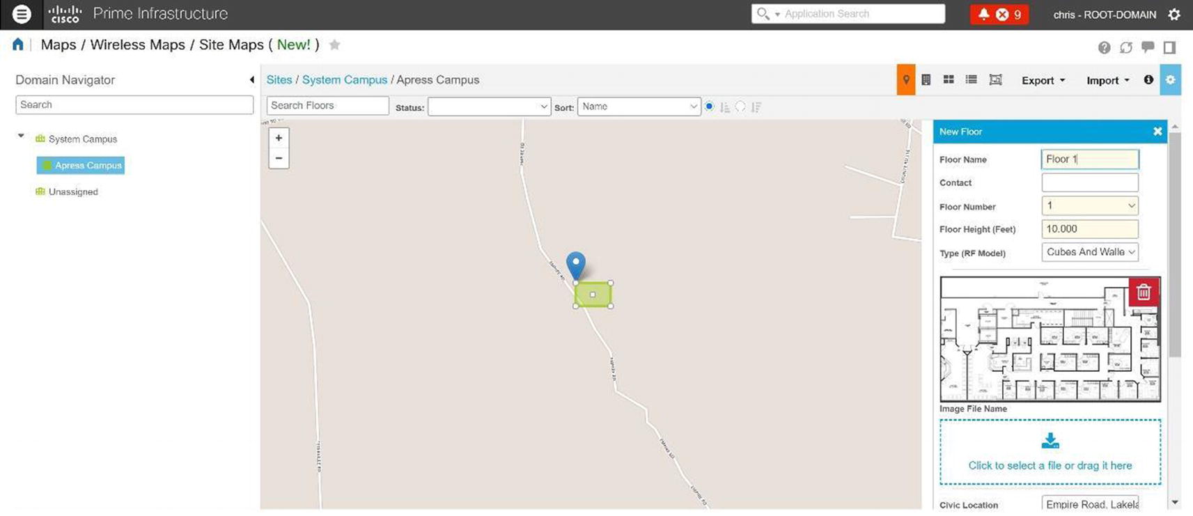
Cisco Prime floor plan upload
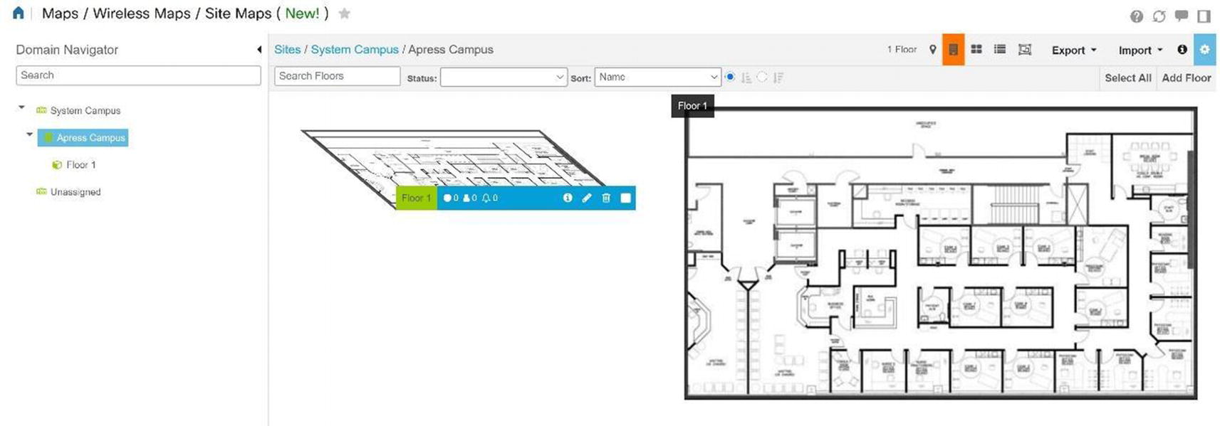
Cisco Prime floor plan
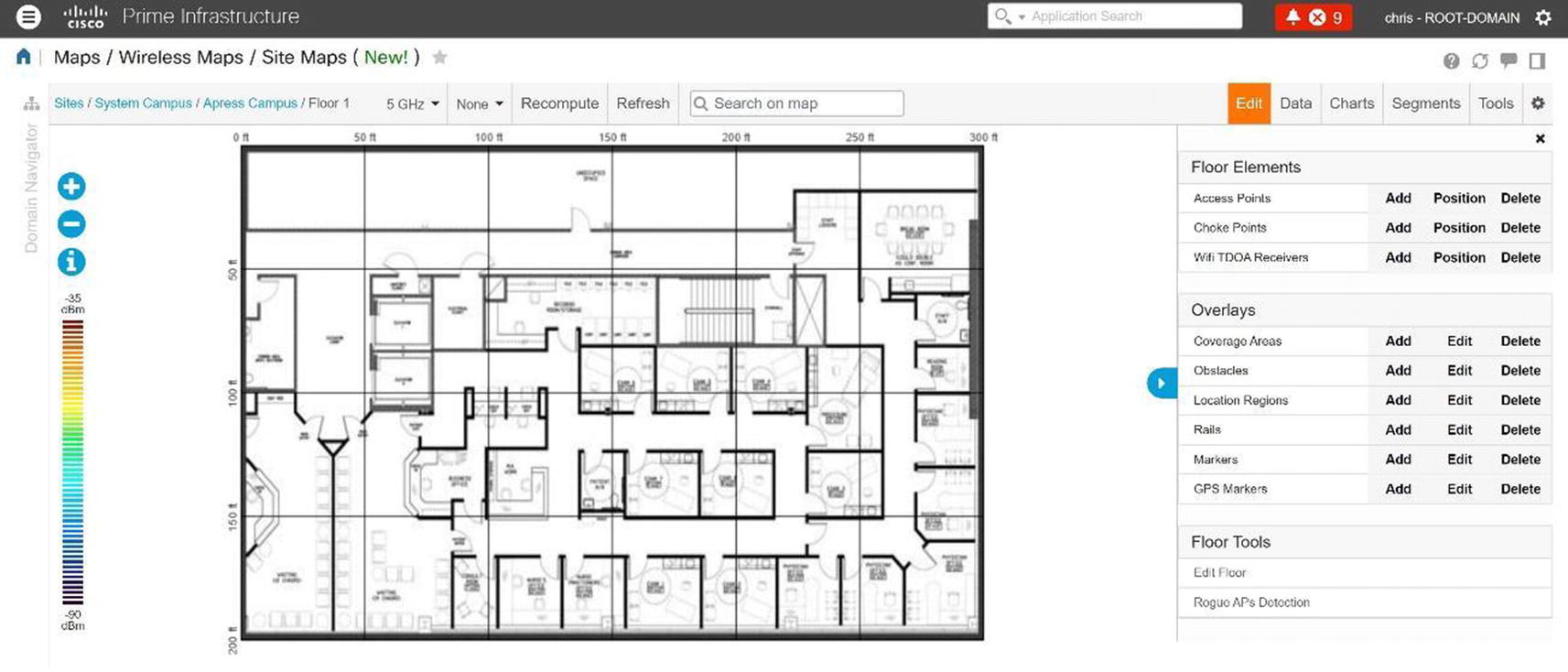
Cisco Prime site map floor plan edit

Cisco Prime site map AP addition
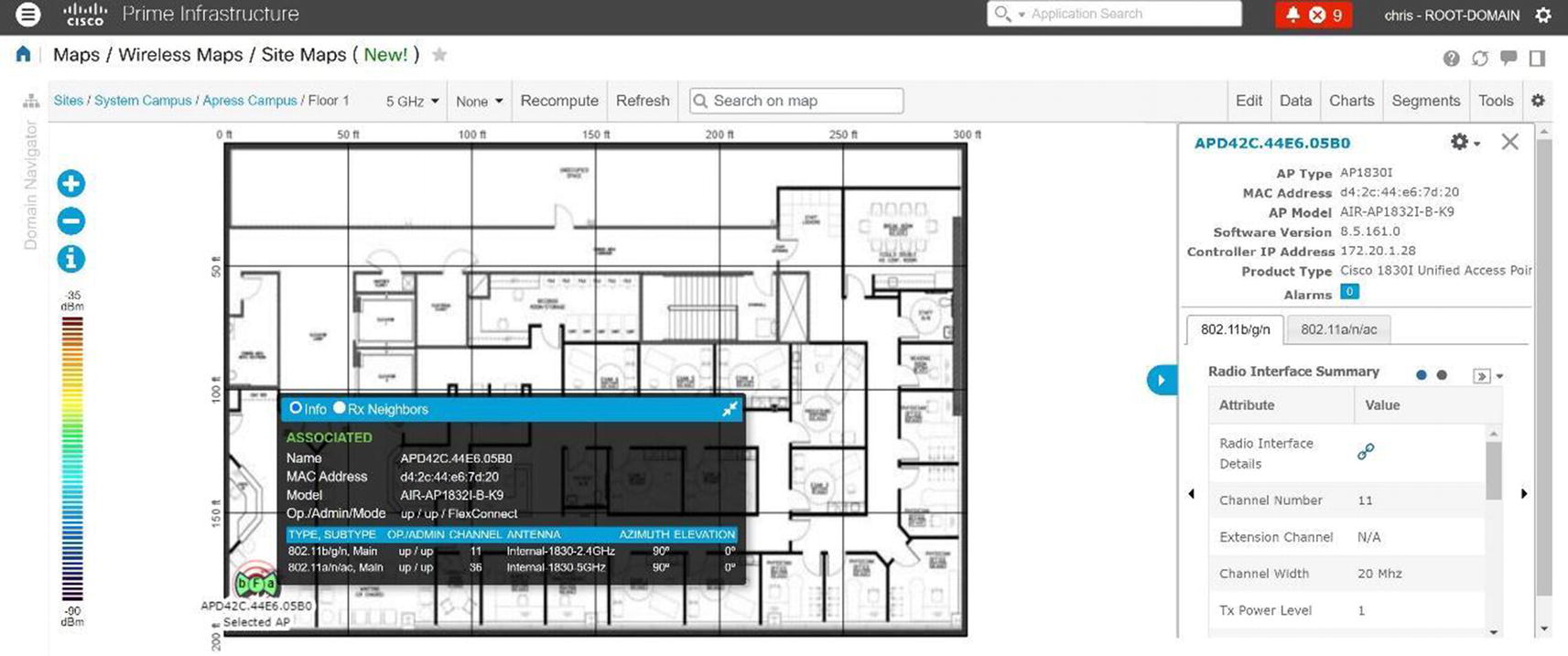
Cisco Prime site map AP details
On the map if you have a client and click it, we see information related to the client to include the username and MAC address of the client.
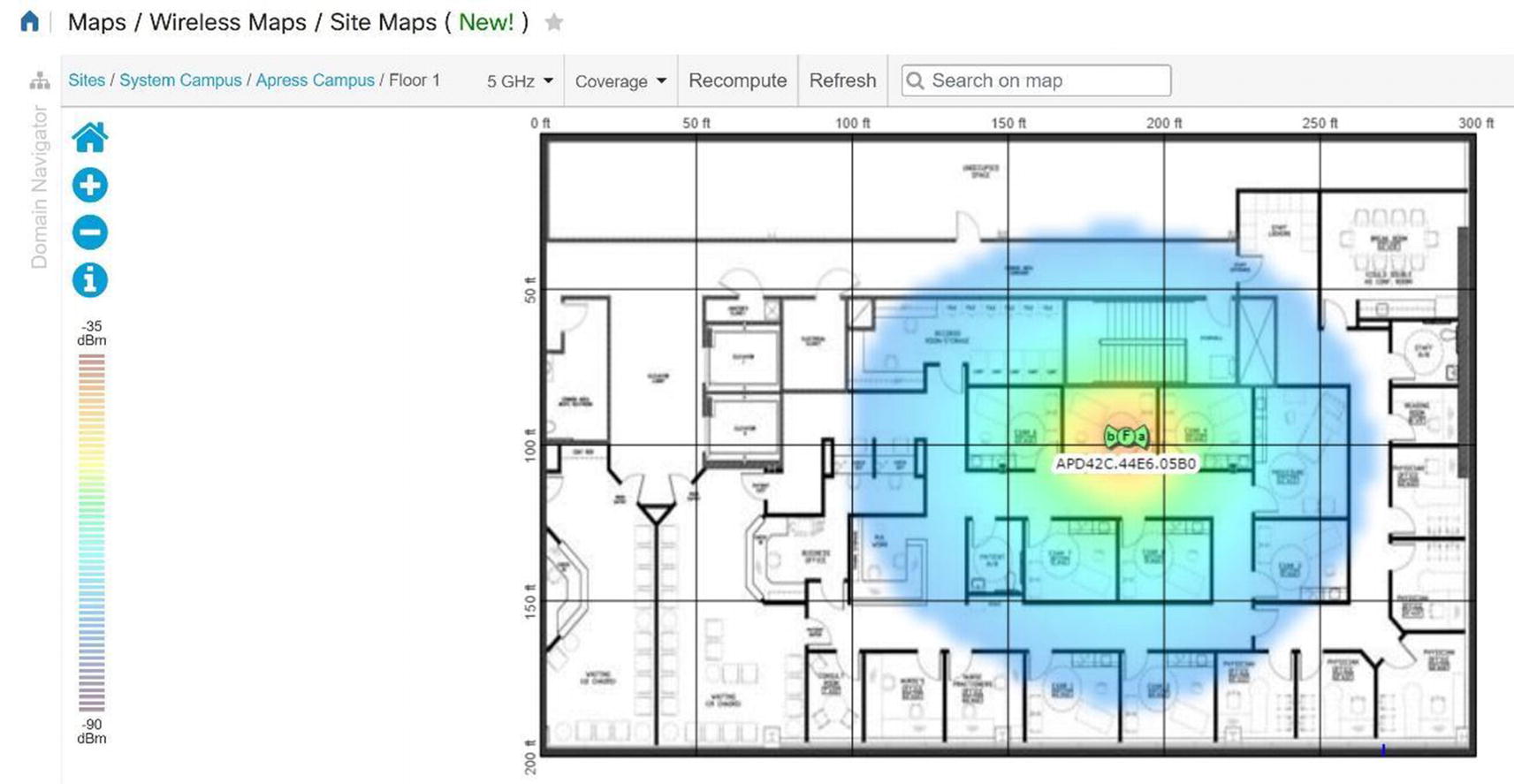
Cisco Prime site map coverage area
Select Rogue APs to see where rogue APs are located.
Prime Infrastructure Configuration
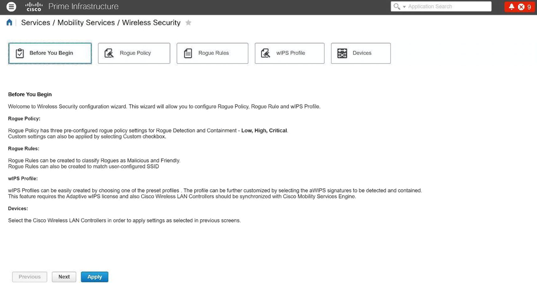
Cisco Prime Wireless Security

Cisco Prime rogue policy
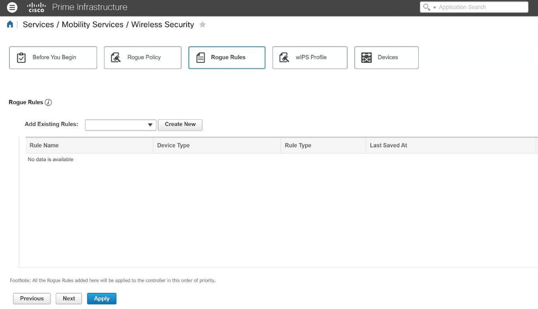
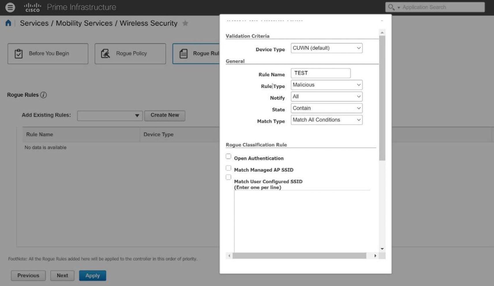
Cisco Prime rogue rule
Cisco Prime rogue policy example

Cisco Prime rogue policy configuration
Threats and Vulnerabilities
There are many threats to a WLAN, as signals propagate through the air for any eavesdropper to view and analyze. This section focuses on those vulnerabilities, as well as ways to prevent security breaches. The only advantage that WLANs have over wired networks is that hackers must be within reasonable physical proximity of the WLAN. Even from several miles away, an attacker can use a cheap antenna to send or sniff Wi-Fi signals. It is good to understand the threats that are in a WLAN, because you can better defend your network. Let’s not forget how the placement of your APs is integral to security of your Wi-Fi network. You want to restrict physical access to your network devices to unauthorized personnel as they can easily be replaced, moved, or reset.
Service Set Identifiers (SSIDs) are treated as a security mechanism, when in reality they are only used to separate WLANs from one another. Sniffing is undetectable, but there are many free and commercial sniffing tools available. SSIDs are broadcasted multiple times per second in each beacon frame from an AP. It is best practice to turn off the SSID broadcast, but even then, your SSID is broadcast whenever a client associates or reassociates with the AP. This SSID can be sniffed and is in the clear. This is one type of gaining access to the network. Sometimes WLANs even use their SSID as their password.
If you use WEP for security, you might as well not use a password. There are many tools that can be used to crack WEP keys in seconds. Sniffing tools can be used to capture usernames or other important information. There are many websites that tell you how to make antennas that can be used to gain access to networks. Wardriving is completed by scanning wireless signals for networks, and there are sites that contain online databases of unprotected wireless networks. The best practice is to use WPA2 to protect your data in the network.
WLANs can easily be disrupted by denial of service (DoS) attacks that can be completed with radio-jamming equipment. Disassociation attacks also occur by posing as an AP and disassociating a device from an AP. Then the attacker can constantly send disassociating attacks to cause DoS. An attacker could also pose as a “man in the middle” to make a client associate with it and then sniff all its data. Air Jack is a tool that can locate a hidden network that does not broadcast its SSID. The tools dissociate a device from an AP, forcing it to reassociate with the AP; it sniffs the SSID in the reassociation packet. It can also transmit invalid authentication requests by spoofing legitimate clients, which causes APs to dissociate legitimate clients. The best way to prevent this type of attack is to make sure that your WLAN coverage ends inside your building and that it does not stretch outside. This can be done by focusing on the placement of the APs and walking around with a scanner to verify that the network does not extend further than you want it to.
Some APs restrict users’ access by MAC addresses, but in this case, it is trivial to sniff packets that contain legitimate users’ MAC addresses, and thus someone can spoof this to be accepted on the network. Rogue APs are unauthorized and not allowed on a network; some users set them up because they think it is easy, and attackers may set them up to steal account information from users. Any device can try to associate with a rogue AP, and the account information used to authenticate can steal a user’s credentials. Do not think that you will be able to identify a rogue AP, because it can mimic your normal AP. Credit card data can be stolen, as well as other confidential information. One-time passwords can be used to minimize the threat, but even a one-time password can be stolen, although it is only valid for that one session. Wireless surveys should be performed on your network to detect rogue APs.
In most instances, malicious wireless snooping and cracking is done to gain access to the Internet without paying a service provider or to conceal malicious activity within an unknowing victim’s wireless network, deflecting any searches for the source of that activity from the individual. Usually, networks that take even moderate care in securing the access points by using encryption and authentication, and by following good physical security practices, won’t be targeted in favor of the low-hanging fruit of an unsecured or poorly secured network. Attackers want the easy target most of the time—so secure your network!
Summary
This chapter covered WLANs and WLAN standards, as well as the basic components of the Cisco wireless network architecture, including access points and controllers. We discussed how to install and configure access points and wireless controller installation and configuration. We covered configuration with ISE and managing your wireless network with Cisco Prime Infrastructure. Finally, we covered wireless security, including encryption, authentication, and WLAN threats and vulnerabilities that exist in wireless networks.
Wireless Exercise
This section provides a wireless exercise to reinforce what was covered in this chapter.
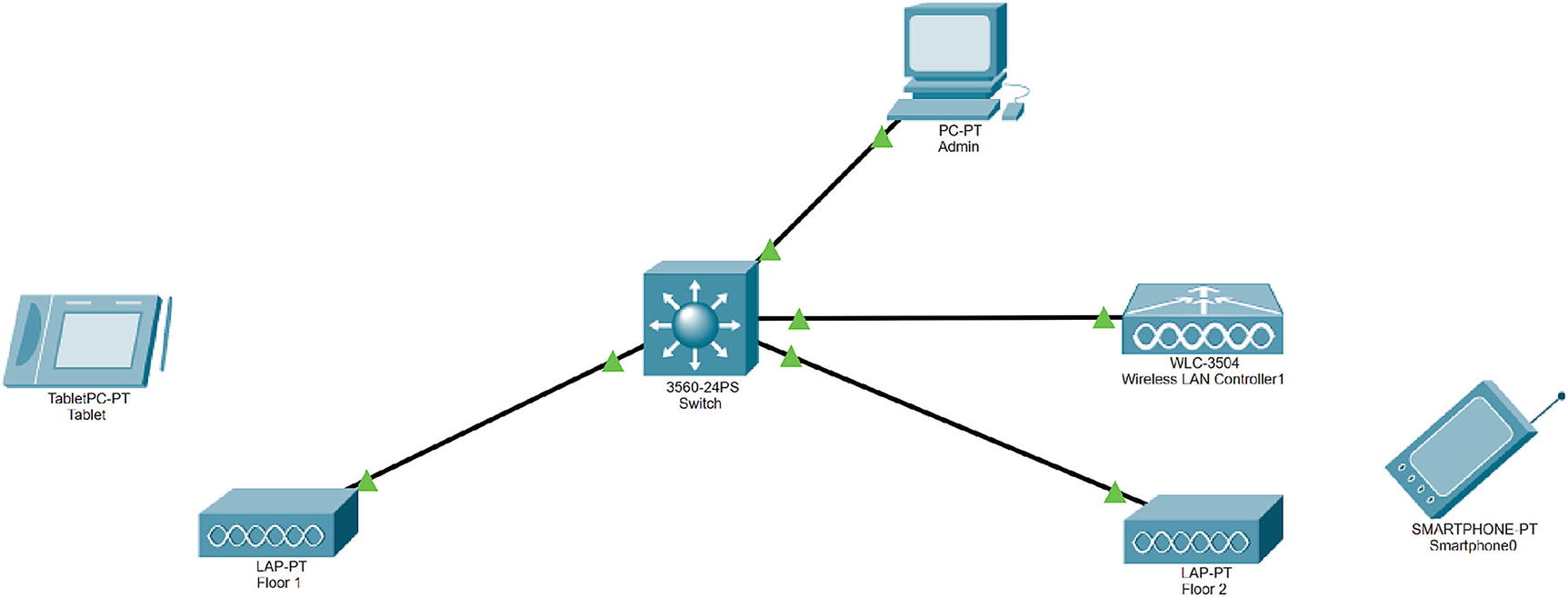
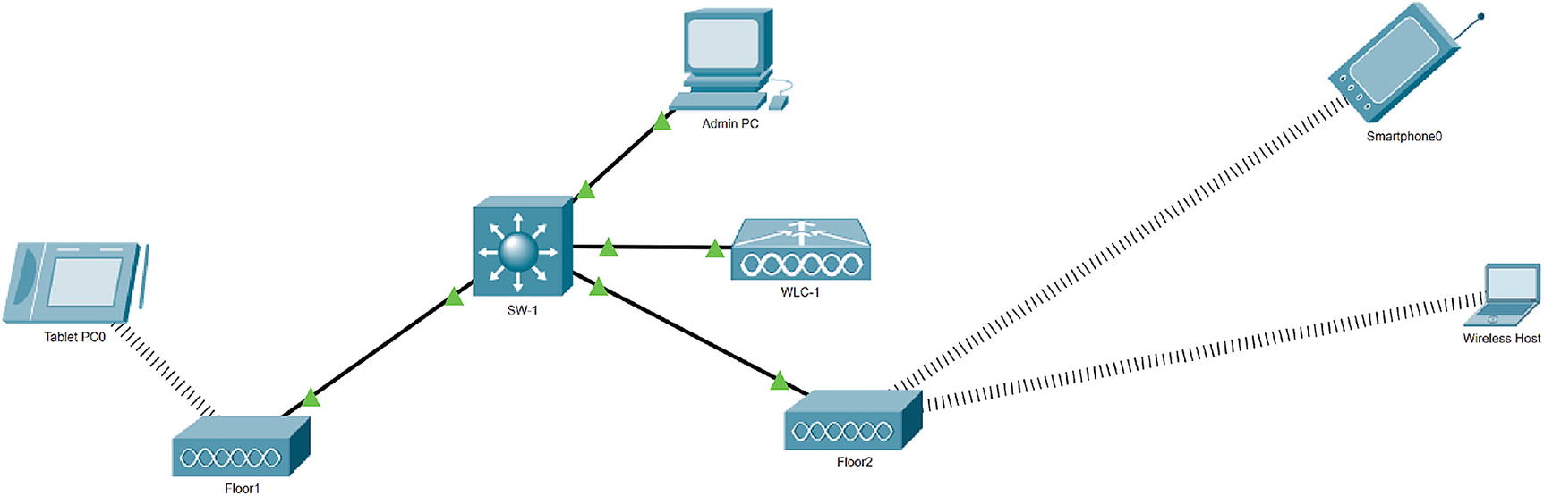
Wireless exercise
Download Cisco Packet Tracer. We are using version 7.3.
Add a switch, a wireless LAN controller, two access points, a tablet, and a mobile phone.

WLC exercise configuration
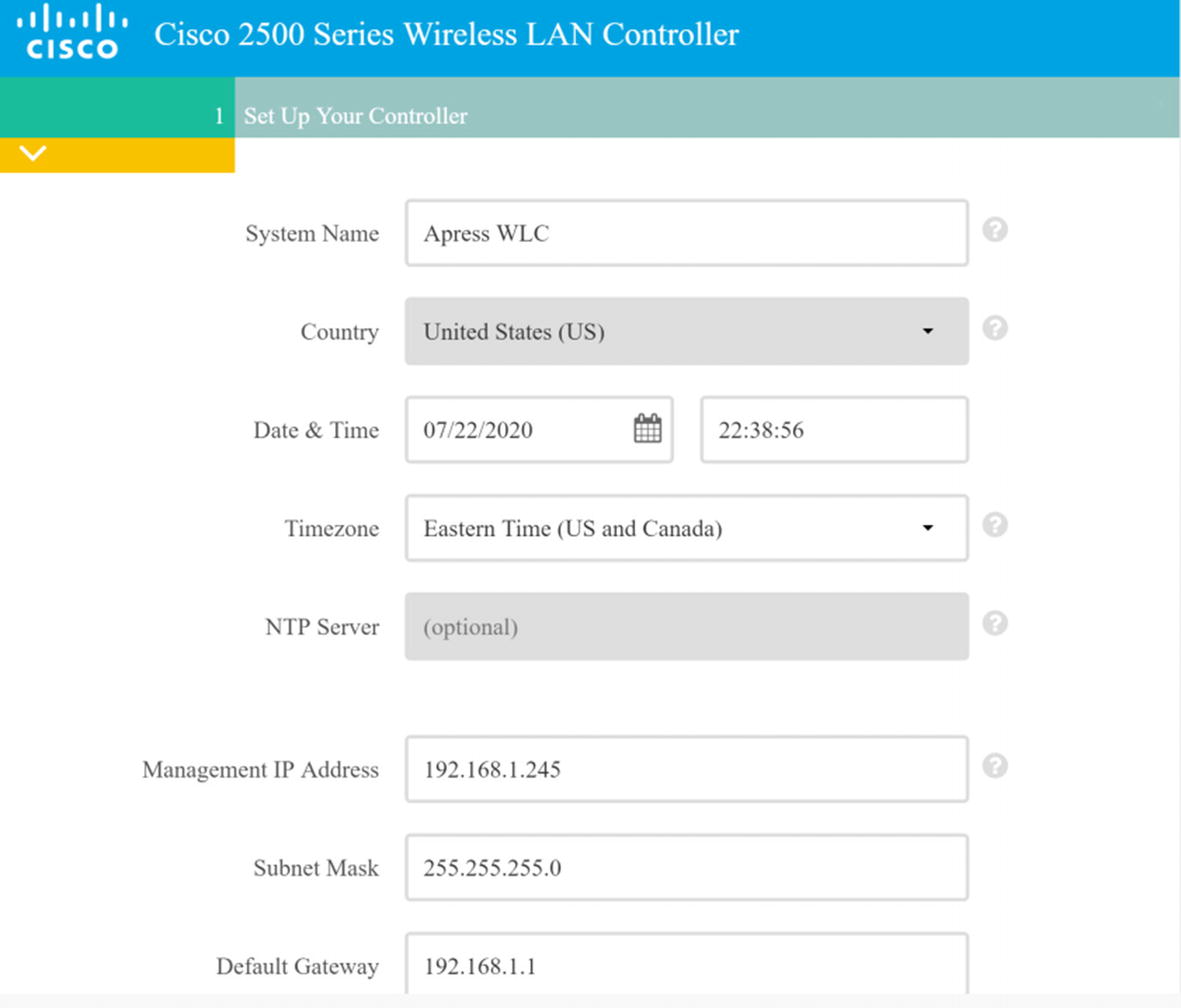
Management IP address: 192.168.1.254
Subnet mask: 255.255.255.0
Default gateway: 192.168.1.1
Next, configure the admin PC to DHCP.
Next, configure the switch with the following settings:
MGMT VLAN 200: 192.168.1.1/24
IP DHCP: Exclude 192.168.1.1 and 192.168.1.254
DHCP pool: 192.168.1.0/24
Connect and configure lightweight access points to the switch:
AP Floor1
AP Floor2
Add a tablet and mobile host.
Exercise Answers
This section provides a walk-through to this chapter’s exercise.
Exercise 1
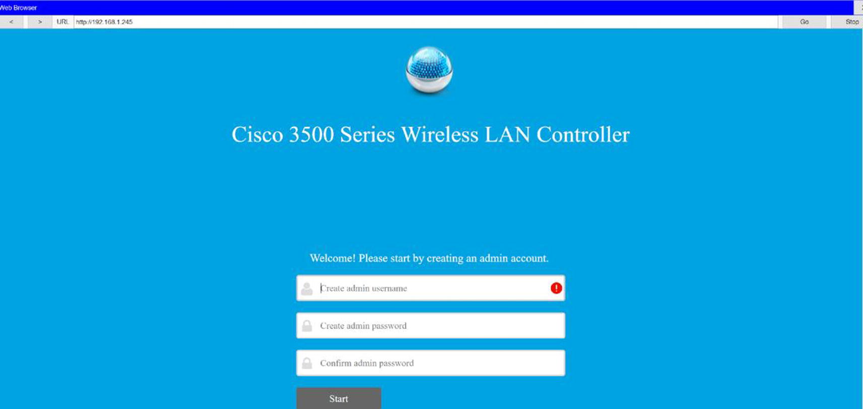
On the admin workstation, go to the browser and navigate to http://192.168.1.254 as shown in Figure 20-80.
WLC configuration
WLC configuration continued
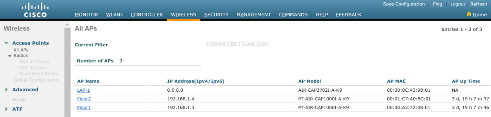
WLC AP summary

WLC WLAN configuration
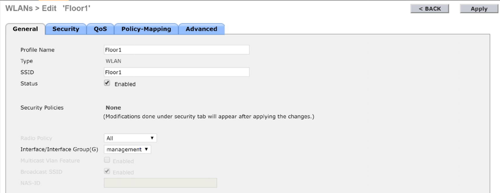
WLC AP Floor1 configuration
Click the Security tab.
Under Layer 2, select WPA+WPA2.
Select WPA2 Policy and select AES for encryption.
Select PSK for pre-shared key.

WLC AP Floor1 security configuration
Repeat for Floor2.
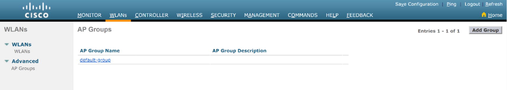
WLC WLAN AP group configuration
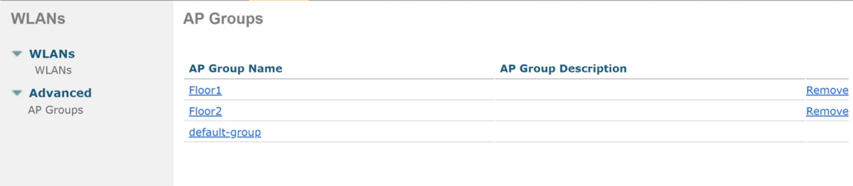
WLC AP group menu
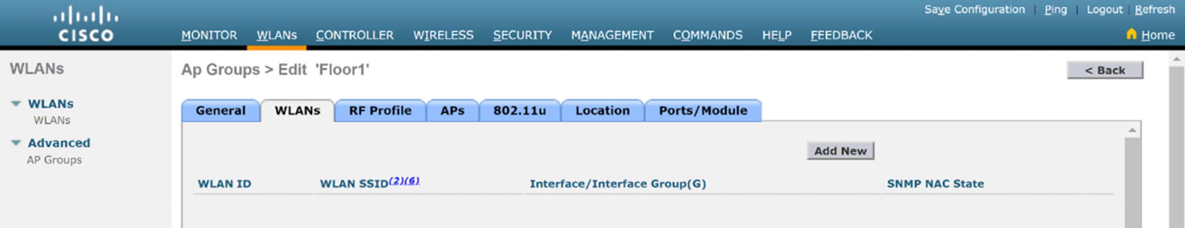
WLC WLAN AP group edit
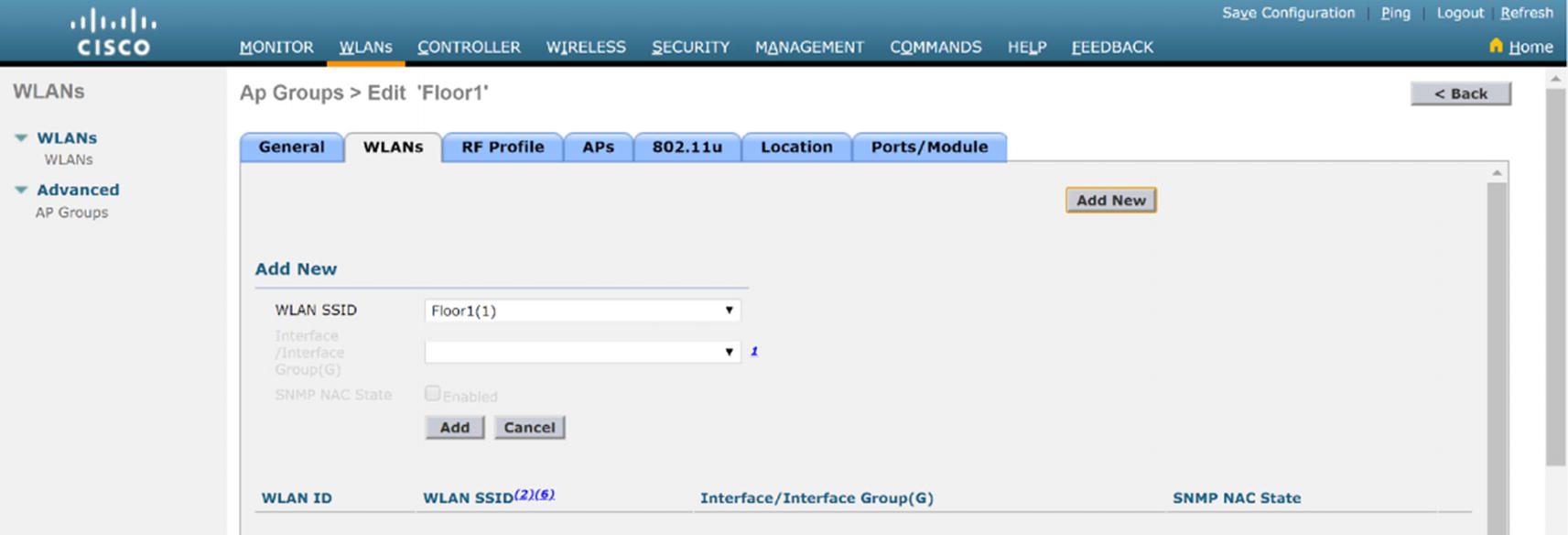
WLC AP group WLAN configuration

WLC AP group AP configuration
Repeat this for Floor2.
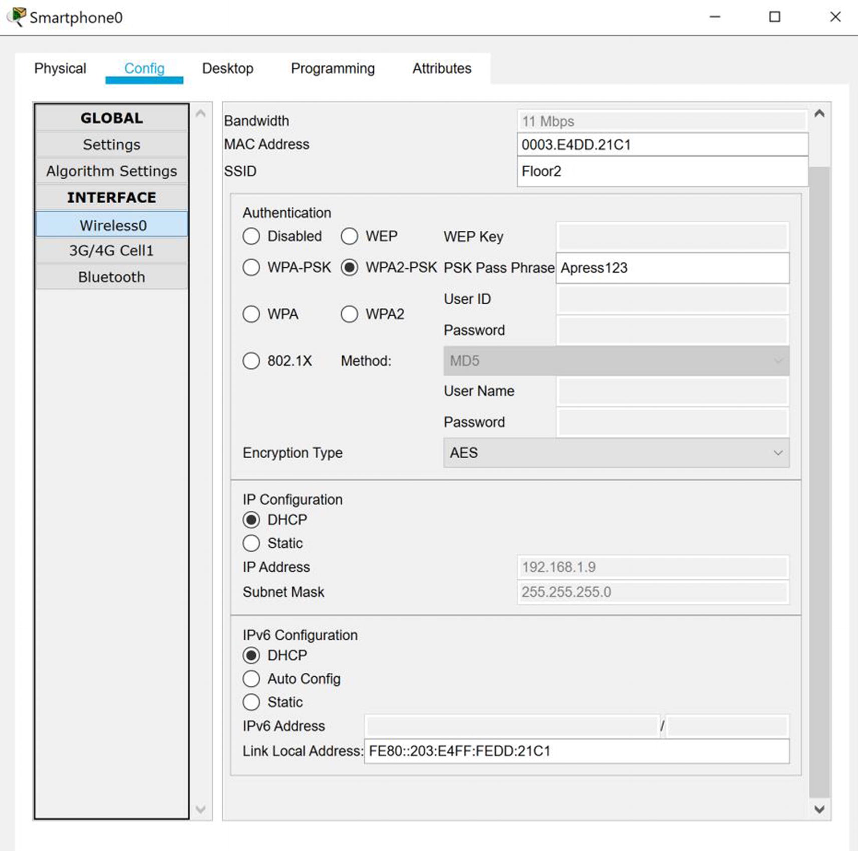
Smartphone AP connection

Tablet AP connection
We can see the wireless devices authenticated and connected to the Floor1 and Floor2 access points.