Chapter 9. Lan QoS
QoS Exam Topics
This chapter covers the following exam topics specific to the QOS exam:
![]() Describe QoS trust boundaries and their significance in LAN-based classification and marking
Describe QoS trust boundaries and their significance in LAN-based classification and marking
![]() Describe and explain the different queuing capabilities available on the Cisco Catalyst 2950 Switch
Describe and explain the different queuing capabilities available on the Cisco Catalyst 2950 Switch
“Why would I go through the hassle of configuring and managing QoS on my LAN, which is already overprovisioned? If I have to, I will just add more bandwidth!”
This is a common statement. Conventional wisdom dictates, “If you have enough bandwidth, you do not need QoS, which is used only for WAN links that do not have enough bandwidth. LANs have plenty of bandwidth, so you are safe.”
Although this sounds reasonable, it is not entirely accurate. Bandwidth is only one of the factors that needs to be taken into consideration for a network that supports real-time applications.
This chapter discusses the QoS features that the Cisco Catalyst 2950 LAN switch offers and examines some recommended configurations designed to prioritized real-time applications across your LAN.
The purpose of the “Do I Know This Already?” quiz is to help you decide whether you need to read the entire chapter. If you already intend to read the entire chapter, you do not necessarily need to answer these questions now.
The 18-question quiz, derived from the major sections in the “Foundation Topics” portion of the chapter, helps you determine how to spend your limited study time.
Table 9-1 outlines the major topics discussed in this chapter and the “Do I Know This Already?” quiz questions that correspond to those topics.
Caution The goal of self-assessment is to gauge your mastery of the topics in this chapter. If you do not know the answer to a question or are only partially sure of the answer, mark this question wrong for purposes of the self-assessment. Giving yourself credit for an answer you correctly guess skews your self-assessment results and might provide you with a false sense of security.
You can find the answers to the “Do I Know This Already?” quiz in Appendix A, “Answers to the ‘Do I Know This Already?’ Quizzes and Q&A Sections.” The suggested choices for your next step are as follows:
![]() 8 or less overall score—Read the entire chapter. This includes the “Foundation Topics,” the “Foundation Summary,” and the “Q&A” sections.
8 or less overall score—Read the entire chapter. This includes the “Foundation Topics,” the “Foundation Summary,” and the “Q&A” sections.
![]() 9 or 10 overall score—If you want more review on these topics, skip to the “Foundation Summary” section and then go to the “Q&A” section. Otherwise, move to the next chapter.
9 or 10 overall score—If you want more review on these topics, skip to the “Foundation Summary” section and then go to the “Q&A” section. Otherwise, move to the next chapter.
|
1. |
What methods does a Catalyst 2950 currently use to classify traffic? a. CoS b. CoS and DSCP c. CoS, DSCP, and access lists d. CoS, DSCP, access lists, and NBAR |
|
2. |
What QoS map needs to be modified on the Catalyst 2950 to allow the switch to match the Layer 2 and Layer 3 currently marked by Cisco IP Phones? a. DSCP to CoS b. CoS to DSCP c. CoS-to-IP Precedence map e. DSCP-to-IP Precedence map f. IP Precedence-to-DSCP map |
|
3. |
By default, what values does the Catalyst 2950 trust? a. CoS b. DSCP c. CoS and DSCP d. None of the above |
|
4. |
Which of the following is not a trust option on the Catalyst 2950? a. Trust CoS b. Trust IP Precedence c. Trust DSCP d. Trust Cisco Phone |
|
5. |
What does the command mls qos trust cos pass-through dscp do? a. Enables trust of CoS values only if a DSCP value is present b. Enables trust of CoS values and does not modify the DSCP value c. Enables trust of CoS only if the DSCP value matches the CoS-to-DSCP map d. Enables trust of DSCP only if a CoS value is present |
|
6. |
How many egress queues are present on each Ethernet interface of the Catalyst 2950? a. 1 b. 2 c. 4 d. 8 |
|
7. |
Which three scheduling methods are supported on the Catalyst 2950? a. Strict priority scheduling b. Custom scheduling c. Strict priority and WRR scheduling d. MDRR scheduling e. WRR scheduling f. FIFO scheduling |
|
8. |
Which scheduling method is configured by default on a Catalyst 2950? a. Strict priority scheduling b. Custom scheduling c. Strict priority and WRR scheduling d. MDRR scheduling e. WRR scheduling f. FIFO scheduling |
|
9. |
Which scheduling method is recommended for networks that transport IP telephony traffic? a. Strict priority scheduling b. Custom scheduling c. Strict priority and WRR scheduling d. MDRR scheduling e. WRR scheduling f. FIFO scheduling |
|
10. |
Which command is used to assign a CoS value of 5 to queue 4? a. wrr-queue cos-map 5 4 b. wrr-queue cos-assign 4 5 c. wrr-queue cos-map 4 5 d. wrr-queue cos-assign 5 4 |
|
11. |
Which of the following commands is used to enable strict priority with WRR scheduling on the Catalyst 2950? a. wrr-queue bandwidth 20 1 80 P b. wrr-queue bandwidth 0 20 1 80 c. wrr-queue bandwidth 20 1 80 0 d. wrr-queue bandwidth P 20 1 80 |
|
12. |
What is a policer? a. A policer measures the data rate of arriving packets, identifies conforming and nonconforming traffic flows, and takes action on the traffic flows based upon the traffic contract. b. A policer measures the available bandwidth of an interface, identifies the traffic peaks, and takes action on peak traffic based upon the traffic contract. c. A policer measures the data rate of arriving packets, identifies known and unknown traffic flows, and takes action on the unknown traffic flows based upon the traffic contract. d. A policer measures the available bandwidth of an interface, identifies the known and unknown traffic flows, and takes action on the unknown traffic flows based upon the traffic contract. |
|
13. |
What is out-of-profile or nonconforming traffic? a. Traffic routed out of the wrong interface b. Received traffic that exceeds the rate specified by the policer c. Received traffic that does not exceed the rate specified by the policer d. Received traffic that has not been defined by the policer |
|
14. |
What can a policer do with nonconforming traffic on a Catalyst 2950? a. Drop it b. Remark the DSCP value c. Remark the CoS value d. A and B e. B and C |
|
15. |
Which of the following commands enables AutoQoS on the Catalyst 2950? a. auto qos trust b. auto qos voip trust c. auto qos trust voip d. auto qos cisco-phone e. auto qos trust cisco-phone |
|
16. |
What does the command auto qos voip trust do? a. Enables trust of CoS on applied interface b. Enables trust of DSCP on applied interface c. Changes CoS-to-DSCP map d. Changes DSCP-to-CoS map e. Enables strict priority scheduling f. Enables strict priority queuing g. A, C, and F h. B, D, and E i. A, B, C, D, and F |
|
17. |
What does the command auto qos voip cisco-phone do? a. Enables trust of CoS for a Cisco IP Phone b. Enables trust of DSCP for a Cisco IP Phone c. Changes CoS-to-DSCP map d. Changes DSCP-to-CoS map e. Enables strict priority scheduling f. Enables strict priority queuing g. A, C, and F h. B, D, and E i. A, B, C, D, and F |
|
18. |
What command can you use to verify AutoQoS on a Catalyst 2950? a. show qos auto b. show auto qos c. show auto cos d. show cos auto |
This chapter describes the concepts of LAN QoS for the Cisco Catalyst 2950 and discusses the following options available to you:
![]() Classification and marking
Classification and marking
![]() Defining trust boundaries
Defining trust boundaries
![]() Congestion management
Congestion management
![]() Policing
Policing
![]() AutoQoS
AutoQoS
LAN quality of service (QoS) is often misunderstood and overlooked. Thanks to conventional wisdom, most network administrators think that they do not require LAN QoS. If your plans include the addition of real-time applications, such as IP telephony or video conferencing, you should include a strategy for LAN QoS while you are in the planning stages of your project. This up-front planning can result in the perceived success or failure of your project in the eyes of the end users.
Suppose that is it 8:30 on a Monday morning. All your fellow employees report to work, simultaneously power on their computers, and begin their day. Their traffic flows through the access layer switches and converges on the uplink port to the distribution layer switch. If the uplink port is smaller than the input port, or the uplink port is oversubscribed, the buffer on the uplink port begins to fill, as shown in Figure 9-1.

For an instant, the buffer of the uplink port can become full, potentially causing packets to drop. In a typical TCP/IP data-networking environment, this is not a concern because the packet is retransmitted. In an environment comprised of real-time applications, such as IP telephony and video conferencing, instantaneous buffer overruns (overflows) can affect the quality of the voice or video streams.
In a Cisco IP Telephony environment, a G.729 digital signal processor (DSP) can rebuild up to 30 ms of lost voice. If the Cisco standard 20 ms per packet has been deployed, a single packet can be dropped without degrading voice quality. If two consecutive voice packets are lost, resulting in 40 ms of lost voice conversation, the DSP cannot compensate, and a clip is heard in the conversation. If the Real-Time Transport Protocol (RTP) stream carries a fax or modem conversation, a single packet results in a modem retrain, whereas two consecutive packets result in a dropped connection.
You cannot remedy these problems by adding bandwidth. Although additional bandwidth capacity might reduce the periods during which congestion occurs, it does not prevent congestion entirely. Many data applications, such as FTP, are very bursty and greedy, consuming as much bandwidth as possible. If the total aggregate bandwidth consumes more than the uplink port’s scheduler can transmit at any given moment in time, congestion can still occur. By classifying the real-time applications on your LAN and scheduling the desired level of service for each real-time application, you can avoid congestion. QoS tools are required to manage the switch’s buffers to minimize loss, delay, and jitter. You must properly enable and configure the QoS parameters in order to set the desired priority by matching a traffic flow with the desired egress queue.
Bandwidth is not a substitute for LAN QoS! LAN QoS is a buffer management issue.
This chapter focuses on the capabilities and configuration needed to provide QoS on a Cisco Catalyst 2950 series switch. The previous edition of this book covered a broader range of LAN information. It is provided on the CD-ROM that is included with this book, for those of you interested in reading about the differences in switches. For those pursing the Implementing Cisco QOS exam, the Cisco Catalyst 2950 is the basis for the LAN QoS questions.
The Catalyst 2950 can be ordered with either a Standard or Enhanced Cisco IOS Software image. From a QoS perspective, the Enhanced IOS version is preferred over the Standard IOS version to deploy the LAN QoS needed to support real-time applications. Table 9-2 lists the key differences in QoS capabilities between the Enhanced and Standard OS versions available for the Catalyst 2950.

Due to the additional QoS capabilities, the Enhanced IOS image should be used when deploying a network that will support real-time applications. The discussion of all QoS features in this chapter assumes that the Catalyst 2950 is running the enhanced IOS image.
Classification describes how a particular traffic flow is identified. Classification is the method of differentiating one stream of traffic from another so that different levels of service can be applied to one traffic stream, while other traffic streams might receive only best-effort service. Classification is the first step in the process of providing QoS guarantees for real-time application traffic.
Marking describes the method used to change values in specific fields of a packet. By changing these values, marking provides a way to inform next-hop devices of a packet’s classification or identification.
Classification on a Catalyst 2950 with the Enhanced IOS images can be achieved by examining the headers of an IP packet or Ethernet frame.
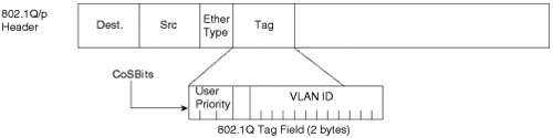
Classification and marking at Layer 2 takes place in the 3-bit User Priority field called class of service (CoS), which resides inside the header of an Ethernet frame. The CoS bits exist inside Ethernet frames only when 802.1Q trunking is used. The field can set eight different binary values, which can be used by the classification features of other QoS tools.
Figure 9-2 shows the general location of the CoS bits inside the 802.1Q headers.
Classification and marking in the Layer 3 header takes place in the type of service (ToS) or Differentiated Services (DS) field. The Precedence and Differentiated Services Code Point (DSCP) fields can be marked with any valid binary value of either 3 or 6 bits, respectively. Figure 9-3 outlines the two fields and their positions inside an IP header.

The Catalyst 2950 has the capability to examine both Layer 2 CoS bits and Layer 3 DSCP bits, using either marking for classification of the received packet. Some devices connected to the switch might not have this capability. For example, a Layer 2 switch examines CoS bits, whereas a router generally is configured to examine the DSCP bits.
Consider a case in which a router, configured to examine the DSCP bits, is connected to a Layer 2 switch, configured to examine CoS bits. In this case, a packet transmitted from the router to the switch may be marked with the desired DSCP value; however, the switch cannot examine the DSCP bits and, therefore, uses the default CoS value configured for the ingress port of the switch, usually 0. This means that the switch cannot maintain the intended level of service for the received packet.
To maintain the intended level of service, the Cisco Catalyst 2950 has the capability to translate the tag from one layer to the other. If the switch receives an Ethernet frame with the CoS bit set to 5, the switch has the capability to mark the DSCP field of the received packet for downstream Layer 3 nodes to use for classification. Conversely, if the switch receives a packet with the DSCP value set to EF (Decimal 46), the switch has the capability to mark the CoS bits of the received frame for connected Layer 2 trunks to use for classification. The mechanisms used for this translation are CoS-DSCP maps and DSCP-CoS maps, respectively.
To show the current state of the CoS-to-DSCP map on the Catalyst 2950, use the show mls qos map cos-dscp command. Example 9-1 shows the CoS-to-DSCP map state of a Catalyst 2950 that has not been configured for QoS.
Example 9-1 Default CoS-to-DSCP Map
Cos-dscp map:
cos: 0 1 2 3 4 5 6 7
--------------------------------
dscp: 0 8 16 24 32 40 48 56
In the default state, a CoS value of 3 is mapped to a DSCP decimal value of 24 (CS3), while a CoS value of 5 is mapped to a DSCP decimal value of 40 (CS5). Table 9-3 lists the DSCP classes associated with the DSCP decimal values.


A Cisco IP Phone marks voice-signaling traffic with a CoS value of 3 and a DSCP class of AF31 (decimal 26). Voice-media traffic is marked with a CoS value of 5 and DSCP class of EF (decimal 46). To keep this marking consistent, CoS-to-DSCP mapping for CoS values of 3 and 5 needs to be modified. This can be accomplished by using the global mls qos map cos-dscp command, as demonstrated in Example 9-2.
Example 9-2 show mls qos map cos-dscp After Modification
2950-ENH#show mls qos map cos-dscp
Cos-dscp map:
cos: 0 1 2 3 4 5 6 7
--------------------------------
dscp: 0 8 16 26 32 46 48 56
The show mls qos map cos-dscp command verifies the change. Comparing the output in Example 9-2 with Example 9-1, you can see that the CoS value of 3 has been mapped to DSCP AF31 (decimal 26) instead of DSCP CS3 (decimal 24), and the CoS value of 5 has been mapped to DSCP EF (decimal 46) instead of DSCP CS5 (decimal 40). If you have used the auto qos option to configure the Catalyst 2950, the switch modifies the CoS-to-DSCP map automatically.
Whereas the CoS-to-DSCP mapping needs to be changed to keep the marking consistent, the DSCP-to-CoS values do not need to be changed. In the default state, the switch places a CoS value of 3 into the 802.1Q header for all packets that it receives with a DSCP value of CS3 (decimal 24) or AF31 (decimal 26) and place a CoS value of 5 in the 802.1Q header for all packets it receives with a DSCP value of CS5 (decimal 40) or EF (decimal 46). The show mls qos map dscp-cos command can be used to verify the DSCP-to-CoS mapping, as demonstrated in Example 9-3.
A trust boundary is the point in your network at which the received CoS or DSCP markings can be trusted. Placing this trust boundary as close as possible to the source of the traffic reduces the processing overhead of downstream devices by allowing all downstream devices to trust the marking they receive and schedule traffic in the proper queue.
By default, the Ethernet interfaces on a Catalyst 2950 are in the untrusted state. This means that any CoS value received on an interface will be overwritten with a CoS value of 0, by default. Because the CoS-to-DSCP map specifies that a CoS value of 0 maps to a DSCP value of 0, all DSCP markings are overwritten with a value of 0 as well. The show mls qos interface command verifies the trust state of a port. Example 9-4 shows the trust state of FastEthernet 0/1 in the default state.
Example 9-4 show mls qos interface
FastEthernet0/1
trust state: not trusted
trust mode: not trusted
COS override: dis
default COS: 0
pass-through: none
trust device: none
To prioritize real-time traffic, you must be able to classify the real-time traffic, so you need some level of trust. Trust boundaries on a Catalyst 2950 can be based upon CoS, DSCP, or a Cisco IP Phone device. Table 9-4 lists the options for configuring the trust state.
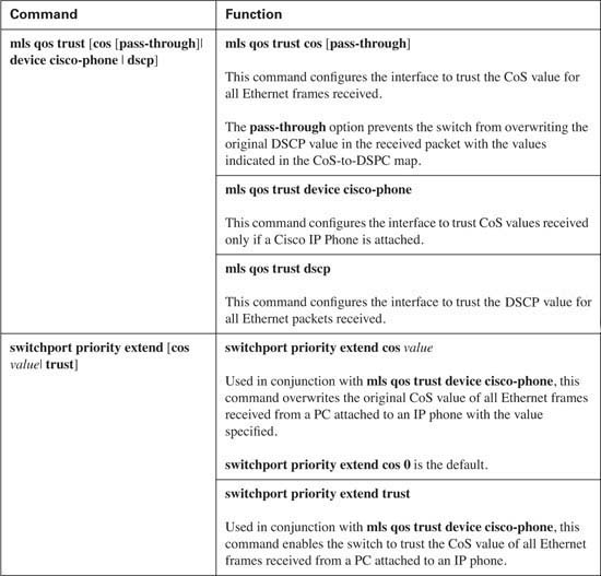
To enable the interface to trust the CoS value received for all Ethernet frames, use the mls qos trust cos command on the interface. Example 9-5 shows the trust state of Fast Ethernet 0/1 that has been configured to trust the received CoS value.
Example 9-5 Trust CoS
In Example 9-5, the CoS value in the 802.1Q header is trusted and the DSCP value is marked based upon the CoS-DSCP map, discussed in the “Layer 2-to-Layer 3 Mapping” section later in this chapter. To enable trust of the received CoS values without modifying the received DSCP value, use the mls qos trust cos pass-through dscp command on the interface.
To trust the DSCP value received on an interface, use the mls qos trust dscp command. Example 9-6 shows the trust state of Fast Ethernet 0/1 that has been configured to trust the received DSCP value.
Example 9-6 Trust DSCP
2950-ENH#show mls qos interface FastEthernet 0/1
FastEthernet0/1
trust mode: trust dscp
default COS: 0
pass-through: none
trust device: none
In Example 9-6, the switch will trust all DSCP values received on Fast Ethernet 0/1.
So far, you have looked at trust based upon CoS and DSCP values received on an Ethernet interface. What happens when a Cisco IP Phone is connected to Fast Ethernet 0/3, but the IP phone has a PC connected to its local switch port? You need to be able to trust the IP Phone without trusting the attached PC. If you trust CoS or DSCP on Fast Ethernet 0/3, you are trusting all packets received on that interface. If the attached PC has the capability to mark its traffic, how will the switch know who to trust and who not to trust? This situation is not acceptable in an IP telephony environment. To trust the marking from a Cisco IP phone but not trust the marking from the attached PC, use the mls qos trust device cisco-phone command on the Ethernet interface. Example 9-7 shows interface Fast Ethernet 0/3 configured to trust an attached Cisco IP Phone.
Example 9-7 Trust Cisco IP Phones
2950-ENH#show mls qos interface FastEthernet0/3
FastEthernet0/3
trust state: not trusted
trust mode: not trusted
COS override: dis
default COS: 0
pass-through: none
Enabling trust based upon device cisco-phone tells the switch to detect an attached Cisco IP Phone using Cisco Discovery Protocol (CDP) version 2. If a Cisco IP Phone is not discovered on the interface, the trust state remains untrusted, and any markings received on this interface are overwritten with the default CoS value configured on the port. By default, this value is 0.
If a Cisco IP Phone is discovered on the interface, the switch will extend the trust boundary to the Cisco IP Phone. Voice-signaling packets marked with a CoS value of 3 and voice-medial traffic marked with a CoS value of 5 will be trusted by the switch. By default, the traffic from the attached PC will be overwritten with a CoS value of 0. This behavior can be modified to either substitute a different CoS value for the received traffic or trust the original values received from the PC attached to the IP phone. The interface command switchport priority extend [cos value | trust] modifies this behavior. Although it is possible to modify or trust the CoS values received from a PC attached to a Cisco IP Phone, recommended practice is to keep the default switchport priority extend 0 on the interface.
At times, it is desirable to tag all incoming traffic with a specific CoS value. Suppose that you have an application server connected to interface Fast Ethernet 0/10 and that this interface does not have the ability to mark CoS or DSCP values. You have determined that this application server should receive better treatment than best effort but not quite as good as voice and video traffic. Assume that this class of service on your network is classified using a CoS value of 2. You need some mechanism to place this value on all untagged frames received on interface Fast Ethernet 0/10. You can use the mls qos cos command to accomplish this. Table 9-5 lists the options for configuring the default CoS value.
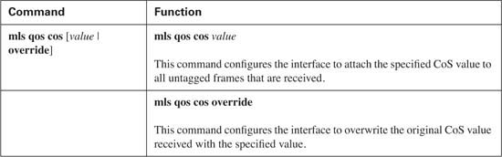
Use the mls qos cos 2 command to set the default CoS value of untagged Ethernet frames received on interface Fast Ethernet 0/10 to a value of 2. In Example 9-8, all untagged Ethernet frames received on interface Fast Ethernet 0/10 will be tagged with a CoS value of 2.
Example 9-8 Default CoS Value
2950-ENH#show mls qos interface fastEthernet 0/10
02:38:06: %SYS-5-CONFIG_I: Configured from console by console
FastEthernet0/1
trust state: not trusted
trust mode: not trusted
default COS: 2
trust device: none
Suppose the application server connected to interface Fast Ethernet 0/10 does have the capability to mark CoS values; however, for whatever reason, the CoS value the switch receives is CoS 1. To maintain the same class of service, this value needs to be changed. Because the mls qos cos 2 command marks untagged frames, it does not affect the frames received from the application server now that it is tagging frames with a CoS value of 1. Use the mlq qos cos override command on interface Fast Ethernet 0/10 to overwrite the CoS value of 1 with the configured CoS value of 2. This command overrides any trust state of the interface, CoS or DSCP, and places the configured default CoS value of 2 in every frame.
Now that you know how to set a default CoS value or trust attached devices based upon CoS, DSCP, or device, you are ready to look at how these parameters would be configured in an IP telephony environment. Figure 9-4 illustrates a typical IP telephony network.
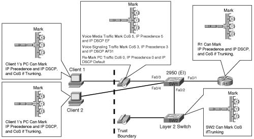
Notice the devices connected to the Catalyst 2950 (SW1). Interface Fast Ethernet 0/1 is connected to Router R1. If R1 supports 802.1Q, SW1 can be configured to trust the CoS value received on interface Ethernet 0/1. However, routers typically classify and mark packets based upon Layer 3 markings and SW1 has the capability to perceive these same markings, so DSCP values can also be used to classify traffic. Because R1 is on the trusted side of the trust boundary, SW1 will be configured to trust all DSCP values received on interface Fast Ethernet 0/1.
Interface Fast Ethernet 0/2 is connected to switch SW2. Assume that an 802.1Q trunk exists between SW1 and SW2, which has the capability to classify and mark based only upon Layer 2 CoS values. Because SW2 is on the trusted side of the trust boundary, SW1 will be configured to trust the CoS values received on interface Fast Ethernet 0/2.
Interface Fast Ethernet 0/3 is connected to a Cisco IP Phone, which has a PC named Client 1 connected to its switch port. Client 1 has the capability to mark CoS and DSCP values. The Cisco IP Phone is on the trusted side of the trust boundary; however, the PC is on the untrusted side. SW1 will be configured to trust the device cisco-phone on interface Fast Ethernet 0/3. By default, all traffic from Client 1 will be reclassified with a CoS value of 0.
Interface Fast Ethernet 0/4 is connected to a PC named Client 2, which has the capability to mark CoS and DSCP values. Because Client 2 is on the untrusted side of the trust boundary, SW1 will leave interface Fast Ethernet in the default, or untrusted, state. This action causes any markings received on interface Fast Ethernet to be overwritten with a value of 0.
Example 9-9 shows the configuration necessary to implement the trust boundary.
Example 9-9 Trust Configuration
switchport mode trunk
interface FastEthernet0/2
switchport mode trunk
interface FastEthernet0/3
switchport voice vlan 100
!
interface FastEthernet0/4
!
Notice that interface Fast Ethernet 0/4 has no configuration, because the desired state for this interface is the default state of untrusted.
This section discusses how the Modular QoS CLI (MQC) can be used to classify and mark packets specifically on the Catalyst 2950. For more information about the classification and marking capabilities of MQC, refer to the “Cisco Modular QoS CLI” section of Chapter 3, “MQC, QPM, and AutoQoS.”
MQC allows the Catalyst 2950 to identify inbound traffic and place a DSCP and CoS value on that traffic flow. Downstream nodes on the trusted side of the trust boundary can then use these marks to offer the desired level of service for that traffic. Figure 9-5 shows the addition of a video server into the IP telephony network

Assume that the video server does not have the capability to mark DSCP values; however, the desire is to offer priority to video traffic over best-effort traffic.
You have determined that this application should be classified with a DSPC value of AF41 (decimal 34). Although you could mark all inbound traffic with a CoS value of 4, upon consulting the CoS-to-DSCP map in Example 9-1, you see that a CoS of 4 is currently mapped to a DSCP value of CS4 (decimal 32). You need to classify this traffic with a DSCP value of AF41 (decimal 34), so you need to either change the CoS-to-DSCP map or use a method other than applying a default CoS. Assume that you chose the latter. The MQC can be used to classify the traffic from the video server and mark the DSCP value.
The first step in prioritizing the video traffic is to identify the traffic. Because the video server in this example is not capable of marking CoS or DSCP, you must use some other method of identification. The Catalyst 2950 has the capability to use Cisco traditional IP standard access lists, IP extended access lists, and MAC access lists to identify traffic. Using an IP standard access list that matches the source of the video server, traffic from the video server can be identified and placed into a class map. Assume that the IP address of the video server is 10.2.1.1. Example 9-10 shows the configuration necessary.
Example 9-10 Identifying the Video Traffic Using an IP Access List
Once the video traffic has been identified, the Catalyst 2950 needs to place a mark on the traffic for the downstream node to act upon. The Catalyst 2950 offers the capability to set a DSCP value for this traffic. A policy map is used to set the traffic identified in class-map video to a DSCP value of AF41 (decimal 34). Finally, the policy map is applied to all incoming traffic on interface Fast Ethernet 0/5 using the service-policy input command. Example 9-11 shows the necessary configuration.
Example 9-11 Marking the Video Traffic
match access-group 1
!
policy-map video
set ip dscp 34
interface FastEthernet0/5
access-list 1 permit 10.2.1.1
!
The service-policy input command indicates the direction in which the policy map is applied. With this configuration, the switch places a DSCP value of AF31 in each packet received from the video server on interface Fast Ethernet 0/5. MQC on the Catalyst 2950 is used to modify traffic into the switch, so currently there is no option to apply a service policy in the outbound direction. A single service-policy input command can be used per Ethernet interface.
Suppose you need to identify the video traffic without specifying the IP address of the video server. You can use a MAC access list in this case. The marking process would remain the same as the IP access list example; however, the means of identifying the traffic would change. Assume that the MAC address of the video server is 0001.0000.0001. Example 9-12 shows the configuration needed to accomplish this.
Example 9-12 Identifying the Video Traffic Using a MAC Access List
policy-map videoMAC
class videoMAC
set ip dscp 34
!
permit host 0001.0000.0001 any
interface FastEthernet0/5
service-policy input videoMAC
!
Because the switch has an internal DSCP-to-CoS map, the DSCP value of AF41 (decimal 34) in both examples will be automatically mapped to the CoS value of 4 by the Catalyst 2950 for use by connect 802.1Q trunks.
The show access-lists command can be used to verify that the access lists are configured on the switch. Example 9-13 shows both the IP access list and MAC access list created in the previous section.
Example 9-13 show access-lists
Standard IP access list 1
permit 10.2.1.1
Extended MAC access list videoMAC
permit host 0001.0000.0001 any
The show class-map [class-map name] command is used to verify that the class map has been configured with the desired match parameter. Example 9-14 shows the class maps for both the videoIP and videoMAC classes configured in the previous section.
Example 9-14 show class-map
Class Map match-all videoIP (id 3)
Match access-group 1
2950-ENH#show class-map videoMAC
Class Map match-all videoMAC (id 5)
Match access-group name videoMAC
The show policy-map [policy-map name] command is used to verify that the policy map has been configured with the desired class-map and set parameters. Example 9-15 shows the class maps for both the videoIP and videoMAC classes configured in the previous section.
QoS is required only during the times of congestion on the network. If the switch has the capability to transmit packets as they are received and does not need to buffer packets, there is no need to use the configured QoS. The moment congestion occurs, the configured QoS parameters become necessary. The switch needs to prioritize the received traffic to allow some traffic to be immediately transmitted, such as real-time applications, while buffering other traffic that can be transmitted when congestion abates. This concept is called congestion management.
Each FastEthernet port on a Catalyst 2950 has a single ingress receive queue to service incoming traffic, and four egress transmit queues to schedule outgoing traffic. The ingress queue receives traffic as it is presented to the switch and classifies the traffic based upon the trust, marking, and MQC configuration. After the packet has been received and classified, the switch places the packet in the appropriate egress queue, based upon the CoS value of the Ethernet frame after classification has been completed. Figure 9-6 illustrates the treatment received by packets as they enter the switch.

The egress queues need to be configured to reflect the scheduling desired for each CoS value. Egress queues can be configured on a per-interface basis as strict priority scheduled, Weighted Round Robin (WRR) scheduled, or strict priority and WRR scheduled.
With the strict priority scheduling method, each of the four queues is weighted from 1 to 4, with 1 being the lowest priority and 4 being the highest priority. Traffic is transmitted from the highest priority queue (queue 4) until the queue is empty. After the highest priority queue has been emptied, the traffic in the next highest priority queue (queue 3) is transmitted. If a packet arrives in queue 4 while the switch is transmitting the traffic in queue 3, the switch stops transmitting the traffic waiting in queue 3 and begins to transmit the traffic in queue 4. If the switch does not receive additional traffic in queue 4, it continues to transmit the traffic in queue 3 until it is empty. At this point, if there is no traffic in either queue 4 or queue 3, the switch begins to transmit traffic from queue 2, and so on. Figure 9-7 illustrates the packet flow used by strict priority scheduling.

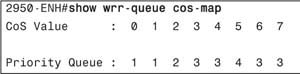
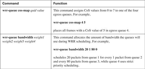
In strict priority scheduling, entrance into a queue is based upon the CoS marking of the packet after the switch has classified the traffic and performed the configured level of trust on the interface. The global wrr-queue cos-map [queue id] [cos values] command matches a specified priority queue with the desired CoS value.
Assume that you have IP telephony, video, and data applications on your network. Classification has already been configured and the desired CoS value is associated with the identified traffic. You now need to prioritize the applications at the egress queue in the following order, with the top application receiving the highest priority:
![]() IP telephony media streams: CoS 5
IP telephony media streams: CoS 5
![]() Video and IP telephony signaling traffic: CoS 4 and CoS 3 respectively
Video and IP telephony signaling traffic: CoS 4 and CoS 3 respectively
![]() Premium data applications: CoS 2
Premium data applications: CoS 2
![]() Best effort traffic: CoS 0 and CoS 1
Best effort traffic: CoS 0 and CoS 1
Assigning traffic with a CoS value of 5 to queue 4 ensures that the IP telephony traffic is always serviced first. Assigning traffic with a CoS value of 4 or a CoS value of 3 to queue 3 ensures that video and IP telephony signaling are sent if there is currently no IP telephony media traffic in queue 4. And so on. Example 9-16 shows the configuration needed to prioritize traffic at the egress port in the specified order.
Example 9-16 Strict Priority Scheduling
2950-ENH(config)#wrr-queue cos-map 2 2
2950-ENH(config)#wrr-queue cos-map 3 3 4 6 7
2950-ENH(config)#wrr-queue cos-map 4 5
CoS values 6 and 7 have been placed in queue 3. These values are reserved for other purposes such as routing updates and bridge protocol data units (BPDUs) and should never be placed in the lower priority queues.
Use the show wrr-queue cos-map command to verify that the correct CoS values is using the desired queue. Example 9-17 shows that the correct priority queues are populated with the desired CoS values as specified.
Strict priority scheduling offers the capability to guarantee that the highest priority traffic is always transmitted first, minimizing delay for that class of traffic. However, strict priority scheduling has the potential of starving the lower priority queues if the higher priority queues are consuming the full bandwidth of the interface for extended periods of time.
Strict priority scheduling is the default scheduling method used by the Catalyst 2950.
Weighted Round Robin (WRR) scheduling eliminates the potential of starving the lower priority queues by assigning a weight to each queue. A weight is defined as the importance of a queue relative to the remaining queues. Simply stated, this means the number of packets that one queue will transmit is relative to the number of packets the remaining queues will transmit.
For example, assume that the strict priority scheduling from the previous section is in effect on your network. IP telephony traffic and video traffic are flowing without an issue. Premium data applications occasionally time out, but due to the heavy loads of higher priority traffic, the best-effort traffic continually stalls for brief periods of time. To remedy this situation, you can assign each of the four queues with a weight that specifies a minimum number of packets that must be consecutively transmitted. After this number of packets has been reached, the switch must then move on to the next queue and consecutively transmit the configured minimum number of packets configured for that queue. And so on. Figure 9-8 illustrates the packet flow used by WRR scheduling.

This guarantees that each queue will be able to
![]() Transmit traffic for at least the number of packets specified by the weight value
Transmit traffic for at least the number of packets specified by the weight value
![]() Prevent starvation of the lower priority queues
Prevent starvation of the lower priority queues
Going back to the strict priority queue example, assume that you want to guarantee bandwidth to all queues to prevent starvation and you want to transmit a minimum of
![]() 50 packets in queue 4
50 packets in queue 4
![]() 25 packets in queue 3
25 packets in queue 3
![]() 10 packets in queue 2
10 packets in queue 2
![]() 5 packets in queue 1
5 packets in queue 1
This can be accomplished using the global wrr-queue bandwidth [q1 weight] [q2 weight] [q3 weight] [q4 weight] command, where weight is expressed in the number of packets relative to each queue. Example 9-18 shows the configuration necessary to implement WRR with the discussed values.

Use the show wrr-queue bandwidth command to verify that the desired number of packets will be transmitted from each queue. Example 9-19 shows that the number of packets scheduled for transmission from each queue follows the design specification.
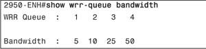
WRR scheduling offers the capability to guarantee bandwidth to traffic in each queue. This configuration prevents queue starvation for the lower priority queues; however, it does not provide a delay guarantee for any traffic. Real-time applications such as voice traffic require a minimum amount of delay and may suffer if too many packets are transmitted in front of voice packets. In this example, the queues will transmit a total of 40 packets before the switch will transmit from queue 4 again
![]() Queue 3 will transmit 25 packets.
Queue 3 will transmit 25 packets.
![]() Queue 2 will transmit 10 packets.
Queue 2 will transmit 10 packets.
![]() Queue 1 will transmit 5 packets.
Queue 1 will transmit 5 packets.
This added delay might cause quality issues in a voice conversation if the voice packet arrives at the destination beyond the designed delay budget.
Strict priority and WRR scheduling combines the benefits of both strict priority scheduling and WRR scheduling by providing a scheduling method that allows for a single strict priority queue and a WRR scheduling method for the remaining three queues. Queue 4 is configured as the strict priority queue, offering the capability to guarantee a minimal amount of delay to traffic within this queue. The remaining three queues are configured with WRR scheduling, which guarantees a minimal amount of bandwidth to each queue when the single strict priority queue is not transmitting. By restricting access into the strict priority queue to real-time applications that require it, such as IP telephony media streams, starvation will not occur in the three remaining queues. Figure 9-9 illustrates the packet flow used by strict priority and WRR scheduling.
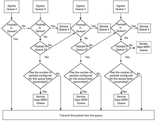
To enable strict priority and WRR scheduling on the Catalyst 2950, use the global wrr-queue bandwidth [q1 weight] [q2 weight] [q3 weight] [q4 weight] command, where the weight of queue 4 is configured as 0. Going back to the WRR scheduling example, suppose you needed to guarantee minimal delay for IP telephony media streams. Because this traffic has been classified with a CoS value of 5 and placed into queue 4, you simply need to change the weight assigned to queue 4 from 50 to 0. Example 9-20 shows the configuration necessary to implement strict priority and WRR scheduling.
Example 9-20 Strict Priority Queuing
wrr-queue cos-map 1 0 1
wrr-queue cos-map 2 2
wrr-queue cos-map 3 3 4 6 7
wrr-queue cos-map 4 5
!
The three remaining WRR queues use the assigned weights to determine the amount of remaining bandwidth that each WRR queue will receive after the strict priority queue has been serviced. In Example 9-20, queue 1 is configured for 5, queue 2 is configured for 10, and queue 3 is configured for 25. This means that queue 2 will receive twice as much of the remaining bandwidth as queue 1, while queue 3 will received five times as much of the remaining bandwidth as queue 1.
Use the show wrr-queue bandwidth command to verify that queue 4 has been configured as the priority queue and the desired number of packets will be transmitted from each of the remaining three queues. Example 9-21 shows that strict priority queuing has been enabled on queue 4 while the three remaining queues follow the WRR design specification.

Although three methods of scheduling are available to you, strict priority queuing is the preferred scheduling method for networks that support real-time applications, such as IP telephony. The addition of the strict priority queue guarantees minimal delay to real-time applications while the WRR scheduler provides bandwidth guarantees to the reaming three queues. Table 9-6 lists the commands used to configure the scheduling options discussed in this section.
At times, your network can become congested with unnecessary or unwanted traffic, such as an FTP server that is sending more data than desired. As the amount of this traffic grows, it can begin to starve out the more desirable traffic, causing business applications to timeout, hampering the productivity of your end users. A mechanism to limit the less desirable traffic needs to be implemented to prevent this situation. This mechanism is called policing.
A policer measures the data rate of arriving packets, identifies conforming and nonconforming traffic flows, and takes action on the traffic flows based upon the traffic contract.
Policing involves creating a policy, or traffic contract, that defines the acceptable amount of traffic for a particular class of service. After a policy has been established, a policer is configured to measure the data rate of arriving packets. The policer identifies conforming and nonconforming traffic flows and takes action on the traffic flows based on the traffic contract. Traffic within this defined limit is considered in profile or conforming traffic, while traffic that exceeds the defined limit is considered out of profile or nonconforming traffic. The policer has the capability to either drop or remark nonconforming traffic.
Consider the network in Figure 9-10.

An FTP server has been added to interface Fast Ethernet 0/6 of a Catalyst 2950. You have been instructed to limit the FTP traffic generated by the server to 5 Mbps; however, during periods of light utilization, you should allow the FTP server to use as much bandwidth as is available. You can use a policer to accomplish this task.
First you need to determine the priority level that will be offered to the FTP traffic in the conforming state and in the nonconforming state. Assume that the priority of applications configured on this network is in the following order, with the top application receiving the highest priority:
1. IP telephony media streams: DSCP EF
2. Video and IP telephony signaling traffic: DSCP AF41 and DSCP AF31, respectively
3. Premium data applications: DSCP AF21
4. Best-effort traffic: DSCP 0
From this priority list, you determine that the conforming FTP traffic will receive a DSCP value of AF21 while nonconforming traffic will receive a DSCP value of 0. This allows the network to treat the first 5 Mbps of FTP traffic as a premium data application, while treating FTP traffic that exceeds the 5-Mbps limit to best-effort service.
MQC needs to be configured to classify, mark, and police the FTP traffic. Because all FTP traffic originates from the FTP server, (the IP address for which is 10.2.1.2) you can use an access list to match the traffic. The access list will then be applied to the class map as demonstrated in Example 9-22.
Example 9-22 Classifying FTP Traffic for Policing
match access-group 2
!
access-list 2 permit 10.2.1.2
A policy map is created for the traffic that matches the class map policeftp. The class policeftp within the policy map policeftp will be configured to mark the IP DSCP value of all matched traffic to DSCP AF21 (decimal 18). Next, you need to configure a policer for the class policeftp. Table 9-7 lists the options available to a policer on a Catalyst 2950.

Because the design specifications call for 5000000 (5 Mbps) of conforming traffic with an exceed option of reclassifying all nonconforming traffic with a DSPC value of 0, the policer command you would need to use under the class policeftp would be police 5000000 8192 exceed-action dscp 0. The burst size was not specified in the design specification, so the minimum burst size (8 Kbps) is used because this is a required parameter. Finally, the service-policy input policeftp command will be configured on interface Fast Ethernet 0/6 to apply the policy map policeftp and activate classification, marking, and policing for this example. Example 9-23 shows the configuration for implementing classification, marking, and policing on interface FastEthernet 0/6.
Example 9-23 Policing FTP Traffic
match access-group 2
!
policy-map policeftp
class policeftp
police 5000000 8192 exceed-action dscp 0
!
interface FastEthernet0/6
access-list 2 permit 10.2.1.2
!
Because a single policer can be applied to a class under the policy-map statement using MQC, you can define multiple policers per interface if multiple classes are defined under the policy map. 10/100 Fast Ethernet interfaces have the capability to support six different policers, configured under a single policy map. Gigabit Ethernet interfaces have the capability to support 60 different policers, configured under a single policy map. In both interface types, the exceed-action option allows for nonconforming traffic to be either dropped or reclassified with a different DSCP value. Notice that the service-policy input command was used to apply the policer to interface FastEthernet 0/6. Policing can be applied only to the ingress of the Catalyst 2950.
The show policy-map [policy-map name] command verifies that the policy map has been configured with the desired class map, policing, and marking. Example 9-24 shows the output for show policy-map policeftp.
Example 9-24 Verifying Policing Policy-Map
Policy Map policeftp
class policeftp
set ip dscp 18
police 5000000 8192 exceed-action dscp 0
For more information on policing concepts and configuration examples for Cisco routers, see Chapter 6, “Traffic Policing and Shaping.”
Understanding and configuring QoS across your network can be a complex and tricky undertaking. Several questions await you:
![]() Who should I trust?
Who should I trust?
![]() How do I trust them?
How do I trust them?
![]() Should I trust them at Layer 2?
Should I trust them at Layer 2?
![]() Layer 3?
Layer 3?
![]() Higher?
Higher?
After trust has been established, new questions arise:
![]() How do I identify the important applications on my network?
How do I identify the important applications on my network?
![]() How do I ensure that important applications are marked for easy identification by downstream nodes?
How do I ensure that important applications are marked for easy identification by downstream nodes?
![]() How do I prioritize one application over another?
How do I prioritize one application over another?
![]() Which egress queue should each application use?
Which egress queue should each application use?
![]() What percentage of bandwidth should each queue receive?
What percentage of bandwidth should each queue receive?
![]() Should I be using policing?
Should I be using policing?
![]() Is the current classification acceptable for use by downstream nodes?
Is the current classification acceptable for use by downstream nodes?
Encountering QoS for the first time can be a daunting experience. There are many factors to consider when planning a network to support real-time applications. Cisco has responded to this complexity dilemma by creating a method that simplifies the trust boundary, classification, and scheduling configuration by automatically applying Cisco QoS best practices for IP telephony traffic. This method is called AutoQoS.
AutoQoS on the Catalyst 2950 consists of the two commands listed and defined in Table 9-8.
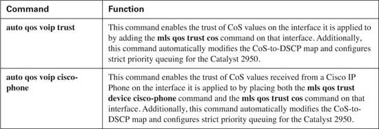
Figure 9-11 illustrates where the commands might be placed.

The auto qos voip cisco-phone command is configured on interface Fast Ethernet 0/3. This command enables the trust for the connected Cisco IP Phone by placing the commands mls qos trust device cisco-phone and mls qos trust cos on interface Fast Ethernet 0/3. Example 9-25 shows this process.
Example 9-25 auto qos voip cisco-phone Configuration
2950-ENH(config-if)#auto qos voip cisco-phone2950-ENH#show running-config
Building configuration...
. . .
!
interface FastEthernet0/3
switchport voice vlan 100
mls qos trust cos
spanning-tree portfast
!
. . .
The switch uses CDP version 2 packets to determine if an IP phone is truly attached to this interface. If an IP phone is discovered by CDP, the trust boundary is extended to the IP phone and the switch then trusts the CoS values received from the IP phone for voice-media traffic (CoS 5) and voice-signaling traffic (CoS 3). By default, trust is not extended to the attached PC (Client 1), so packets received from Client 1 are reclassified with a CoS value of 0.
If an IP phone is not discovered on interface Fast Ethernet 0/3 using CDP version 2, the interface remains in the untrusted state. Any traffic received on this interface is reclassified with a CoS value of 0.
The auto qos voip trust command is used to trust the CoS values of connected devices. Unlike the qos voip cisco-phone command, the auto qos voip trust command does not verify a connected device before trusting received CoS values. If a connected device has the capability to mark a CoS value, it will be trusted, so the auto qos voip trust command is useful for extending the trust boundary to connect 802.1Q trunks. In Figure 9-11, the auto qos voip trust command is configured on interface Fast Ethernet 0/2 because a Layer 2 switch using an 802.1Q trunk is attached to that interface. This causes the switch to place the mls qos trust cos command on interface Fast Ethernet 0/2, indicating that all CoS values received on this interface will be trusted. Example 9-26 shows this process.
Interface Fast Ethernet 0/1 in Figure 9-11 states that “auto qos voip trust might be applied here.” The might depends on the configuration of the router attached to this interface. The auto qos voip trust command places mls qos trust cos on the interface. If the attached router is capable and has been configured to provide an 802.1Q trunk to the switch, adding the auto qos voip trust to interface Fast Ethernet 0/1 will accomplish the desired effect. If the attached router is not capable or has not been configured to provide an 802.1Q trunk to the switch, the switch will use the default value for untagged frames, even though the attached router may be configured for classification based upon DSCP. In this case, AutoQoS will not accomplish the desired result. The mls qos trust dscp command needs to be placed on interface Fast Ethernet 0/1. Example 9-27 shows the configuration needed.
Example 9-27 Manual Trust of DSCP
2950-ENH(config-if)#mls qos trust dscp2950-ENH#show running-config
Building configuration...
. . .
!
interface FastEthernet0/1
. . .
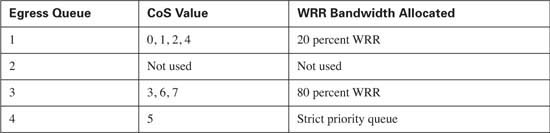
So far, this section has discussed the effect that AutoQoS has on trust boundaries. AutoQoS also offers the benefit of automatically configuring classification and queue scheduling for an IP telephony network. Placing either the auto qos voip trust command or the auto qos voip cisco-phone command on an interface enables this automatic configuration. After AutoQoS is enabled, the switch places all packets with a CoS value of 0, 1, 2, or 4 in egress queue 1. Egress queue 1 will be allocated 20 packets for transmission or, expressed in other terms, 20 percent of the bandwidth allocated to the WRR scheduler. All packets with a CoS value of 3, 6, or 7 will be placed in egress queue number 3. Queue number 3 will be allocated 80 packets for transmission or, expressed in other terms, 80 percent of the bandwidth allocated to the WRR scheduler. All packets with a CoS value of 5 will be placed in queue 4, which will be configured to act as the strict priority queue. Table 9-9 lists these values.
You can verify these values by using the show auto qos command, as demonstrated in Example 9-28.
Example 9-28 show auto qos
Initial configuration applied by AutoQoS:
wrr-queue bandwidth 20 1 80 0no wrr-queue cos-map
wrr-queue cos-map 1 0 1 2 4
wrr-queue cos-map 3 3 6 7
wrr-queue cos-map 4 5
interface FastEthernet0/2
mls qos trust cos
!
interface FastEthernet0/3
mls qos trust device cisco-phone
mls qos trust cos
Notice that the global command wrr-queue bandwidth 20 1 80 0 has a 1 configured for egress queue 2; however, egress queue 2 is defined as not used. In this case, the value of 1 represents a single packet (1 percent) for every 80 (80 percent) from queue 3, and a single packet (1 percent) for every 20 (20 percent) from queue 1. This allows an easy translation from packets to percentages. Because there are no CoS values associated with egress queue 2, no traffic will ever reach that queue and, therefore, it will not be used to transmit traffic in this configuration.
Also notice that the global command mls qos map cos-dscp 0 8 16 26 32 46 48 56 has been added to the configuration of the switch. Refer to the “Layer 2-to-Layer 3 Mapping” section of this chapter, which discussed that the default CoS-to-DSCP mapping did not match the values presented by Cisco IP Phones. Example 9-29 shows the default CoS-to-DSCP mapping for the Catalyst 2950.

Because AutoQoS configures the QoS parameters based upon the needs of an IP telephony network, the CoS-to-DSCP mapping changes to match the values presented by Cisco IP Phones. A CoS value of 3 will be mapped to a DSCP value of 26, while a CoS value of 5 will by mapped to a DSCP value of 46 using the global command mls qos map cos-dscp 0 8 16 26 32 46 48 56. The show mls qos map cos-dscp command verifies the changes made by AutoQoS, as demonstrated in Example 9-30.

Using AutoQoS can help simplify the configuration of QoS on your network by minimizing mistakes and omissions. AutoQoS is a great tool that is focused toward preparing your network for the addition of IP telephony. If you plan to use AutoQoS in your network, recommended practice is that you enable AutoQoS before you configure QoS parameters. QoS parameters can be modified to suit the needs of your network after AutoQoS has been enabled.
Note After reading this chapter, take a moment to review the section “AutoQoS VoIP Configuration for IOS Switches” in Chapter 3. For more information on AutoQoS and the benefits it offers other Cisco platforms, see the section “Cisco AutoQoS Feature” in Chapter 3.
The “Foundation Summary” is a collection of tables and figures that provides a convenient review of many key concepts in this chapter. For those of you already comfortable with the topics in this chapter, this summary can help you recall a few details. For those of you who just read this chapter, this review should help solidify some key facts. For any of you doing your final preparation before the exam, these tables and figures are a convenient way to review the day before the exam.
Table 9-10 lists the key differences in QoS capabilities between the Enhanced and Standard OS versions available for the Catalyst 2950.

Figure 9-12 shows the general location of the CoS field inside the 802.1Q headers.
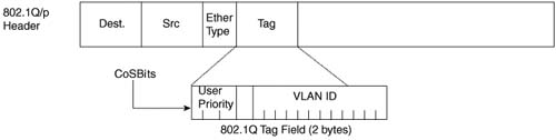
Figure 9-13 outlines the two fields and their positions inside an IP header.

Table 9-11 lists the DSCP classes associated with the DSCP decimal values.

Table 9-12 lists the options for configuring the trust state.

Table 9-13 lists the options for configuring the default CoS value.
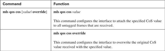
Figure 9-14 illustrates the treatment received by packets as they enter the switch.

Figure 9-15 illustrates the packet flow used by strict priority scheduling.

Figure 9-16 illustrates the packet flow used by WRR scheduling.

Figure 9-17 illustrates the packet flow used by strict priority queuing.
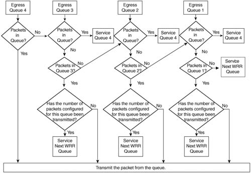
Table 9-14 lists the commands used to configure the available scheduling options.

Table 9-15 lists the options available to a policer on a Catalyst 2950.

AutoQoS on the Catalyst 2950 consists of the two commands listed and defined in Table 9-16.
Table 9-16 AutoQoS Commands
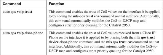
Figure 9-18 illustrates where the commands might be placed.
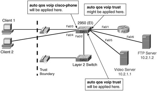
Table 9-17 lists the classification and scheduling options configured by AutoQoS.

This book attempts to cover the breadth and depth of QoS as covered on the QoS exam (642-641). However, you might want to read more about topics in this chapter, or other classification and marking topics.
For more on the topics in this chapter:
![]() Cisco 2950 QoS Configuration Guide (http://www.cisco.com/univercd/cc/td/doc/product/lan/cat2950/12119ea1/2950scg/swqos.htm)
Cisco 2950 QoS Configuration Guide (http://www.cisco.com/univercd/cc/td/doc/product/lan/cat2950/12119ea1/2950scg/swqos.htm)
![]() “Cisco AutoQoS White Paper” (http://cisco.com/en/US/tech/tk543/tk759/technologies_white_paper09186a00801348bc.shtml)
“Cisco AutoQoS White Paper” (http://cisco.com/en/US/tech/tk543/tk759/technologies_white_paper09186a00801348bc.shtml)
For design-related guidance:
![]() “Cisco AVVID Network Infrastructure Enterprise Quality of Service Design” (http://cisco.com/application/pdf/en/us/guest/netsol/ns17/c649/ccmigration_09186a00800d67ed.pdf)
“Cisco AVVID Network Infrastructure Enterprise Quality of Service Design” (http://cisco.com/application/pdf/en/us/guest/netsol/ns17/c649/ccmigration_09186a00800d67ed.pdf)
As mentioned in the Introduction, you have two choices for review questions. The following questions give you a more difficult challenge than the exam itself by using an open-ended question format. By reviewing now with this more difficult question format, you can exercise your memory better, and prove your conceptual and factual knowledge of this chapter. You can find the answers to these questions in Appendix A.
The second option for practice questions is to use the CD-ROM included with this book, which includes a testing engine and more than 200 questions and drag-and-drop tasks. You should use this CD-ROM nearer to the end of your preparation, for practice with the actual exam format.
|
1. |
Why do you need QoS in the LAN? |
|
2. |
What is buffer overflow and when does it occur? |
|
3. |
What IOS types are available for the Catalyst 2950 and which one is preferred for QoS? |
|
4. |
You have a Catalyst 2950 running the standard IOS image and need to migrate to a Catalyst 2950 running the enhanced IOS image. What are your options to migrate to a Catalyst 2950 running the enhanced IOS image? |
|
5. |
What methods can a Catalyst 2950 currently use to classify traffic? |
|
6. |
What map needs to be changed on the Catalyst 2950 to reflect the current markings of Cisco IP Phones? |
|
7. |
What command is used to verify the CoS-to-DSCP map? |
|
8. |
By default, a Catalyst 2950 maps voice-media traffic and voice-signaling traffic to which DSCP values? |
|
9. |
To keep the DSCP values of the voice-media traffic and the voice-signaling traffic consistent between the IP phones and the Catalyst 2950, which DSCP values need to be configured on the Catalyst 2950? |
|
10. |
By default, what values does the Catalyst 2950 trust? |
|
11. |
Name two of the three markings or devices that the Catalyst 2950 can use to extend a trust boundary. |
|
12. |
Where is the trust command configured on a Catalyst 2950? |
|
13. |
What does the switchport priority extend cos 0 command do? |
|
14. |
What does the mls qos trust cos pass-through dscp command do? |
|
15. |
What command enables the trust of a Cisco IP Phone on a Catalyst 2950? |
|
16. |
How does the Catalyst 2950 determine whether a Cisco IP Phone is connected to a port configured to trust device cisco-phone? |
|
17. |
What happens if an interface is configured to trust device cisco-phone and a PC is connected to the interface? |
|
18. |
Which command set the default CoS value of an interface to 2 for all untagged frames received? |
|
19. |
What does the command mls qos cos override do? |
|
20. |
What command views the current trust state of interface Fast Ethernet 0/1? |
|
21. |
A router that is not configured for 802.1Q is connected to interface 0/1 of the Catalyst 2950. The router interface forwards a voice-media packet to the switch. What CoS value will the switch receive? |
|
22. |
A router that is not configured for 802.1Q is connected to interface 0/1 of the Catalyst 2950. The switch is configured to trust CoS on this interface. The router interface forwards a voice-media packet to the switch. What DSPC value will the switch use for this packet by default? |
|
23. |
What can MQC be used for on the Catalyst 2950? |
|
24. |
What is a class map used for? |
|
25. |
What is a policy map used for? |
|
26. |
How is a policy map applied to an interface? |
|
27. |
In which direction can a service policy be applied on a Catalyst 2950? |
|
28. |
How many ingress queues are present on each Ethernet interface of the Catalyst 2950? |
|
29. |
How many egress queues are present on each Ethernet interface of the Catalyst 2950? |
|
30. |
What scheduling methods are supported on the Catalyst 2950? |
|
31. |
What mark does the Catalyst 2950 use to determine the proper queue for a packet? |
|
32. |
Which scheduling method is configured by default on a Catalyst 2950? |
|
33. |
Which scheduling method is recommended for networks that transport IP telephony traffic? |
|
34. |
How does strict priority scheduling work? |
|
35. |
What are the advantages and disadvantages of using strict priority scheduling? |
|
36. |
How does Weighted Round Robin scheduling work? |
|
37. |
What are the advantages and disadvantages of WRR scheduling? |
|
38. |
How does strict priority queuing work? |
|
39. |
What queue is configured for the strict priority queue when using strict priority queuing? |
|
40. |
What command assigns a CoS value of 5 to queue 4? |
|
41. |
What command assigns WRR scheduling with queue 1 servicing 5 packets, queue 2 servicing 10 packets, queue 3 servicing 25 packets, and queue 4 servicing 50 packets? |
|
42. |
What command enables the strict priority queue when using strict priority queuing? |
|
43. |
What command verifies that queue 4 has been configured for the priority queue? |
|
44. |
What is a policer? |
|
45. |
What is out of profile or nonconforming traffic? |
|
46. |
What can a policer do with nonconforming traffic on a Catalyst 2950? |
|
47. |
How many policers can be applied to a single 10/100 Ethernet interface on a Catalyst 2950? How about a Gigabit interface on a Catalyst 2950? |
|
48. |
What is the maximum burst size that a policer can use for a 10/100 interface on a Catalyst 2950? |
|
49. |
What is the maximum burst size that a policer can use for a Gigabit interface on a Catalyst 2950? |
|
50. |
What is the minimum traffic rate that a policer can use for conforming traffic for a 10/100 interface on a Catalyst 2950? |
|
51. |
What is the minimum traffic rate that a policer can use for conforming traffic for a Gigabit interface on a Catalyst 2950? |
|
52. |
What commands enables AutoQoS on the Catalyst 2950? |
|
53. |
Where are the auto qos voip trust and auto qos voip cisco-phone commands applied? |
|
54. |
What does the command auto qos voip trust do? |
|
55. |
What does the command auto qos voip cisco-phone do? |
|
56. |
When is configuring trust manually preferred over AutoQoS? |
|
57. |
When AutoQoS is enabled, what CoS values are mapped to queue 1? What percentage of the WRR scheduler does queue 1 receive? |
|
58. |
When AutoQoS is enabled, what CoS values are mapped to queue 2? What percentage of the WRR scheduler does queue 2 receive? |
|
59. |
When AutoQoS is enabled, what CoS values are mapped to queue 3? What percentage of the WRR scheduler does queue 3 receive? |
|
60. |
When AutoQoS is enabled, what CoS values are mapped to queue 4? What percentage of the WRR scheduler does queue 4 receive? |
|
61. |
What command can you use to verify AutoQoS? |