Chapter 7. Congestion Avoidance Through Drop Policies
QoS Exam Objectives
This chapter covers the following exam topics specific to the QoS exam:
![]() Describe the drawbacks tail drop as a congestion control mechanism
Describe the drawbacks tail drop as a congestion control mechanism
![]() Describe the elements of a RED traffic profile
Describe the elements of a RED traffic profile
![]() Describe Weighted Random Early Detection and how it can be used to prevent congestion
Describe Weighted Random Early Detection and how it can be used to prevent congestion
![]() Identify the Cisco IOS commands required to configure and monitor DSCP-based CB-WRED
Identify the Cisco IOS commands required to configure and monitor DSCP-based CB-WRED
![]() Explain how ECN interacts with WRED in Cisco IOS
Explain how ECN interacts with WRED in Cisco IOS
Quality of service (QoS) congestion-avoidance tools help prevent congestion before it occurs. These tools monitor queue depth, and before the queue fills, they drop some packets. The computers sending the packets might reduce the frequency of sending packets in reaction to the packet loss, particularly if the application sending the data uses TCP. In the moments after the congestion-avoidance tool discards packets, congestion is reduced, because less traffic is sent into the network.
Cisco congestion-avoidance tools rely on the behavior of TCP to reduce congestion. TCP flows slow down after packet loss. By discarding some TCP packets before congestion gets bad, congestion-avoidance tools may actually reduce the overall number of packets dropped, and reduce congestion, thereby indirectly reducing delay and jitter.
The first section of this chapter begins with a review of TCP and a description of how TCP slows down after packet loss. Following that, several of the problems that can be solved using congestion-avoidance tools are described, namely tail drop, global synchronization, and TCP starvation. The concepts section of this chapter ends with coverage of Random Early Detection (RED), which defines several algorithms, which are the basis of IOS congestion-avoidance tools.
Weighted RED (WRED) and Explicit Congestion Notification (ECN) are two congestion-avoidance tools available in IOS. These are covered in sequence, with the differences between the two highlighted at the end of the chapter.
The purpose of the “Do I Know This Already?” quiz is to help you decide whether you really need to read the entire chapter. If you already intend to read the entire chapter, you do not necessarily need to answer these questions now.
The 9-question quiz, derived from the major sections in “Foundation Topics” section of this chapter, helps you determine how to spend your limited study time.
Table 7-1 outlines the major topics discussed in this chapter and the “Do I Know This Already?” quiz questions that correspond to those topics.

Use Table 7-1 to record your score.
Caution The goal of self-assessment is to gauge your mastery of the topics in this chapter. If you do not know the answer to a question or are only partially sure of the answer, mark this question wrong for purposes of the self-assessment. Giving yourself credit for an answer you correctly guess skews your self-assessment results and might provide you with a false sense of security.
You can find the answers to the “Do I Know This Already?” quiz in Appendix A, “Answers to the ‘Do I Know This Already?’ Quizzes and Q&A Sections.” The suggested choices for your next step are as follows:
![]() 7 or less overall score—Read the entire chapter. This includes the “Foundation Topics,” the “Foundation Summary,”, and “Q&A” sections.
7 or less overall score—Read the entire chapter. This includes the “Foundation Topics,” the “Foundation Summary,”, and “Q&A” sections.
![]() 8 or 9 overall score—If you want more review on these topics, skip to the “Foundation Summary” section and then go to the “Q&A” section. Otherwise, move to the next chapter.
8 or 9 overall score—If you want more review on these topics, skip to the “Foundation Summary” section and then go to the “Q&A” section. Otherwise, move to the next chapter.
|
1. |
TCP Slow Start controls the rate a TCP sender sends data by controlling: a. Growth of the Advertised Window b. Growth of the Congestion Window c. Calculation of the Average Queue Depth d. The wait-for-acknowledgement timer |
|
2. |
For which of the following WRED categories will WRED discard all packets? a. Tail Drop b. Full Drop c. Random Drop d. Partial Drop e. No Drop |
|
3. |
For which of the following WRED categories will WRED discard a subset of the packets? a. Tail Drop b. Full Drop c. Random Drop d. Partial Drop e. No Drop |
|
4. |
On which of the following types of queues can you enable WRED on routers that are not part of the 7500-series router line? a. On the physical interface b. On a CBWFQ class that has been configured with the bandwidth command c. On an LLQ class that has been configured with the priority command d. On a single FIFO queue created by CB Shaping The next three questions refer to the following configuration snippet: ip cef
! ! The following classes are used in the LLQ configuration applied to S0/0 ! class-map match-all class1 match protocol http url "*important*" class-map match-all class2 match protocol http url "*not-so*" class-map match-all class3 match protocol http ! policy-map wred-q class class1 bandwidth percent 25 random-detect dscp-based random-detect dscp af22 25 35 50 class class2 bandwidth percent 20 random-detect random-detect precedence 2 25 35 50 class class3 bandwidth percent 15 random-detect dscp-based random-detect dscp af22 50 25 35 class class-default random-detect dscp-based random-detect dscp af22 2 25 50 ! interface s0/0 ip address 1.1.1.1 255.255.255.0 random-detect dscp-based random-detect dscp af22 50 25 35 ! interface s0/1 ip address 2.2.2.2 255.255.255.0 service-policy output wred-q |
|
5. |
For which of the following will WRED discard 2% of packets of some precedence or DSCP value, when the average queue depth approaches the maximum threshold? a. On physical interface S0/0 b. On serial 0/1, class class1 c. On serial 0/1, class class2 d. On serial 0/1, class class3 e. On serial 0/1, class class-default f. None of the above |
|
6. |
Imagine a packet marked as AF22. Out which interface or class must the packet be forwarded in order to have a 35% chance of being discarded, assuming that WRED’s average queue depth calculation was approaching the maximum threshold? a. On physical interface S0/0 b. On serial 0/1, class class1 c. On serial 0/1, class class2 d. On serial 0/1, class class3 e. On serial 0/1, class class-default f. None of the above |
|
7. |
Assuming the commands in the configuration snippet were typed into configuration mode in a router, one of the random-detect commands would be rejected. Under which configuration mode can that erroneous command be found? a. On physical interface S0/0 b. On serial 0/1, class class1 c. On serial 0/1, class class2 d. On serial 0/1, class class3 e. On serial 0/1, class class-default f. None of the above |
|
8. |
Imagine that WRED with ECN has been configured for a CBWFQ class. Under which of the following cases could WRED randomly choose to discard a packet, but instead, mark the ECN bits inside the packet header and allowing the packet to pass? a. Average queue depth between the min and max thresholds, plus the incoming packet ECN field set to 00 b. Average queue depth between the min and max thresholds, plus the incoming packet ECN field set to 01 or 10 c. Average queue depth above max threshold, plus the incoming packet ECN field set to 01 or 10 d. Average queue depth between the min and max thresholds, plus the incoming packet TCP ECE flag must be set to “1”, and ECN field must be set to 01 |
|
9. |
Referring to the configuration snippet before question 5, what command would be required to enable ECN for class2 in policy-map wred-q? a. ecn enable b. no ecn disable c. random-detect ecn d. None required – WRED automatically does it if the TCP sender sets the ECN bits correctly |
The term “congestion avoidance” describes a small set of IOS tools that help queues avoid congestion. Queues fill when the cumulative offered load from the various senders of packets exceeds the line rate of the interface (or the shaping rate if shaping is enabled). When more traffic needs to exit the interface than the interface can support, queues form. Queuing tools help us manage the queues; congestion-avoidance tools help us reduce the level of congestion in the queues by selectively dropping packets.
Once again, a QoS tool gives you the opportunity to make tradeoffs between QoS characteristics—in this case, packet loss versus delay and jitter. However, the tradeoff is not so simple in this case. It turns out that by selectively discarding some packets before the queues get completely full, cumulative packet loss can be reduced, and queuing delay and queuing jitter can also be reduced! When you prune a plant, you kill some of the branches, but the plant gets healthier and more beautiful through the process. Similarly, congestion-avoidance tools discard some packets, but in doing so achieve the overall effect of a healthier network.
This chapter begins by explaining the core concepts that create the need for congestion-avoidance tools. Following this discussion, the underlying algorithms, which are based RED, are covered. Finally, the chapter includes coverage of configuration and monitoring for two IOS congestion-avoidance tools, WRED and ECN.
Congestion-avoidance tools rely on the behavior of TCP to reduce congestion. A large percentage of Internet traffic consists of TCP traffic, and TCP senders reduce the rate at which they send packets after packet loss. By purposefully discarding a percentage of packets, congestion-avoidance tools cause some TCP connections to slow down, which reduces congestion.
This section begins with a discussion of User Datagram Protocol (UDP) and TCP behavior when packets are lost. By understanding TCP behavior in particular, you can appreciate what happens as a result of tail drop, which is covered next in this section. Finally, to close this section, RED is covered. The two IOS congestion-avoidance tools both use the underlying concepts of RED.
UDP and TCP behave very differently when packets are lost. UDP, by itself, does not react to packet loss, because UDP does not include any mechanism with which to know whether a packet was lost. TCP senders, however, slow down the rate at which they send after recognizing that a packet was lost. Unlike UDP, TCP includes a field in the TCP header to number each TCP segment (sequence number), and another field used by the receiver to confirm receipt of the packets (acknowledgment number). When a TCP receiver signals that a packet was not received, or if an acknowledgment is not received at all, the TCP sender assumes the packet was lost, and resends the packet. More importantly, the sender also slows down sending data into the network.
TCP uses two separate window sizes that determine the maximum window size of data that can be sent before the sender must stop and wait for an acknowledgment. The first of the two different windowing features of TCP uses the Window field in the TCP header, which is also called the receiver window or the advertised window. The receiver grants the sender the right to send x bytes of data before requiring an acknowledgment, by setting the value x into the Window field of the TCP header. The receiver grants larger and larger windows as time goes on, reaching the point at which the TCP sender never stops sending, with acknowledgments arriving just before a complete window of traffic has been sent.
The second window used by TCP is called the congestion window, or CWND, as defined by RFC 2581. Unlike the advertised window, the congestion window is not communicated between the receiver and sender using fields in the TCP header. Instead, the TCP sender calculates CWND. CWND varies in size much more quickly than does the advertised window, because it was designed to react to congestion in networks.
The TCP sender always uses the lower of the two windows to determine how much data it can send before receiving an acknowledgment. The receiver window is designed to let the receiver prevent the sender from sending data faster than the receiver can process the data. The CWND is designed to let the sender react to network congestion by slowing down its sending rate. It is the variation in the CWND, in reaction to lost packets, which RED relies upon.
To appreciate how RED works, you need to understand the processes by which a TCP sender lowers and increases the CWND. CWND is lowered in response to lost segments. CWND is raised based on the logic defined as the TCP slow start and TCP congestion-avoidance algorithms. In fact, most people use the term “slow start” to describe both features together, in part because they work closely together. The process works like this:
![]() A TCP sender fails to receive an acknowledgment in time, signifying a possible lost packet.
A TCP sender fails to receive an acknowledgment in time, signifying a possible lost packet.
![]() The TCP sender sets CWND to the size of a single segment.
The TCP sender sets CWND to the size of a single segment.
![]() Another variable, called slow start threshold (SSTHRESH) is set to 50 percent of the CWND value before the lost segment.
Another variable, called slow start threshold (SSTHRESH) is set to 50 percent of the CWND value before the lost segment.
![]() After CWND has been lowered, slow start governs how fast the CWND grows up until the CWND has been increased to the value of SSTHRESH.
After CWND has been lowered, slow start governs how fast the CWND grows up until the CWND has been increased to the value of SSTHRESH.
![]() After the slow start phase is complete, congestion avoidance governs how fast CWND grows after CWND > SSTHRESH.
After the slow start phase is complete, congestion avoidance governs how fast CWND grows after CWND > SSTHRESH.
Therefore, when a TCP sender fails to receive an acknowledgment, it reduces the CWND to a very low value (one segment size of window). This process is sometimes called slamming the window or slamming the window shut. The sender progressively increases CWND based first on slow start, and then on congestion avoidance. As you go through this text, remember that the TCP windows use a unit of bytes in reality. To make the discussion a little easier, I have listed the windows as a number of segments, which makes the actual numbers more obvious.
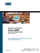
Slow start increases CWND by the maximum segment size for every packet for which it receives an acknowledgment. Because TCP receivers may, and typically do, acknowledge segments well before the full window has been sent by the sender, CWND grows at an exponential rate during slow start—a seemingly contradictory concept. Slow start gets its name from the fact that CWND has been set to a very low value at the beginning of the process, meaning it starts slowly, but slow start does cause CWND to grow quickly.
Figure 7-1 outlines the process of how the TCP sender grows CWND upon the receipt of each acknowledgement.
By increasing CWND when each acknowledgment is received, CWND actually increases at an exponential rate. So, Slow Start might be better called slow start but fast recovery.
Congestion avoidance is the second mechanism that dictates how quickly CWND increases after being lowered. As CWND grows, it begins to approach the original CWND value. If the original packet loss was a result of queue congestion, letting this TCP connection increase back to the original CWND may then induce the same congestion that caused the CWND to be lowered in the first place. Congestion avoidance just reduces the rate of increase for CWND as it approaches the previous CWND value. Once slow start has increased CWND to the value of SSTHRESH, which was set to 50 percent of the original CWND, congestion-avoidance logic replaces the slow start logic for increasing CWND. Congestion avoidance uses a formula that allows CWND to grow more slowly, essentially at a linear rate.
Figure 7-2 shows a graph of CWND with just slow start, and with slow start and congestion avoidance, after the sender times out waiting for an acknowledgment.

Many people do not realize that the slow start process consists of a combination of the slow start algorithm and the congestion-avoidance algorithm. With slow start, CWND is lowered, but it grows quickly. With congestion avoidance, the CWND value grows more slowly as it approaches the previous CWND value. In summary, UDP and TCP react to packet loss in the following ways:
![]() UDP senders do not reduce or increase sending rates as a result of lost packets.
UDP senders do not reduce or increase sending rates as a result of lost packets.
![]() TCP senders do reduce their sending rates as a result of lost packets.
TCP senders do reduce their sending rates as a result of lost packets.
![]() TCP senders decide to use either the receiver window or the CWND, based on whichever is smaller at the time.
TCP senders decide to use either the receiver window or the CWND, based on whichever is smaller at the time.
![]() TCP slow start and congestion avoidance dictate how fast the CWND rises after the window was lowered due to packet loss.
TCP slow start and congestion avoidance dictate how fast the CWND rises after the window was lowered due to packet loss.
Note Depending on the circumstances, TCP sometimes halves CWND in reaction to lost packets, and in some cases it lowers CWND to one segment size, as was described in this first section. The more severe reaction of reducing the window to one segment size was shown in this section for a more complete description of slow start and congestion avoidance. The course upon which the QoS exam combines all these concepts under the term Slow Start.
Tail drop occurs when a packet needs to be added to a queue, but the queue is full, so the router must discard the packet. Yes, tail drop is indeed that simple. However, tail drop results in some interesting behavior in real networks, particularly when most traffic is TCP based, but with some UDP traffic. Of course, the Internet today delivers mostly TCP traffic, because web and email traffic use TCP.
The preceding section described the behavior of a single TCP connection after a single packet loss. Now imagine an Internet router, with 100,000 or more TCP connections running their traffic out of a high-speed interface. The amount of traffic in the combined TCP connections finally exceeds the output line rate, causing the output queue on the interface to fill, which in turn causes tail drop.
What happens to those 100,000 TCP connections after many of them have at least one packet dropped? The TCP connections reduce their CWND; the congestion in the queue abates; the various CWND values increase with slow start, and then with congestion avoidance. Eventually, however, as the CWND values of the collective TCP connections approach the previous CWND value, the congestion occurs again, and the process is repeated. When a large number of TCP connections experience near simultaneous packet loss, the lowering and growth of CWND at about the same time causes the TCP connections to synchronize. The result is called global synchronization. The graph in Figure 7-3 shows this behavior.

The graph shows the results of global synchronization. The router never fully utilizes the bandwidth on the link because the offered rate keeps dropping as a result of synchronization. Note that the overall rate does not drop to almost nothing because not all TCP connections happen to have packets drop when tail drop occurs, and some traffic uses UDP, which does not slow down in reaction to lost packets.
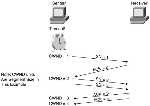
Weighted RED (WRED), when applied to the interface that was tail dropping packets, significantly reduces global synchronization. WRED allows the average output rates to approach line rate, with even more significant throughput improvements, because avoiding congestion and tail drops decreases the overall number of lost packets. Figure 7-4 shows an example graph of the same interface, after WRED was applied.
Another problem can occur if UDP traffic competes with TCP for bandwidth and queue space. Although UDP traffic consumes a much lower percentage of Internet bandwidth than TCP does, UDP can get a disproportionate amount of bandwidth as a result of TCP’s reaction to packet loss. Imagine that on the same Internet router, 20 percent of the offered packets were UDP, and 80 percent TCP. Tail drop causes some TCP and UDP packets to be dropped; however, because the TCP senders slow down, and the UDP senders do not, additional UDP streams from the UDP senders can consume more and more bandwidth during congestion.
Taking the same concept a little deeper, imagine that several people crank up some UDP-based audio or video streaming applications, and that traffic also happens to need to exit this same congested interface. The interface output queue on this Internet router could fill with UDP packets. If a few high-bandwidth UDP applications fill the queue, a larger percentage of TCP packets might get tail dropped—resulting in further reduction of TCP windows, and less TCP traffic relative to the amount of UDP traffic.
The term “TCP starvation” describes the phenomena of the output queue being filled with larger volumes of UDP, causing TCP connections to have packets tail dropped. Tail drop does not distinguish between packets in any way, including whether they are TCP or UDP, or whether the flow uses a lot of bandwidth or just a little bandwidth. TCP connections can be starved for bandwidth because the UDP flows behave poorly in terms of congestion control. Flow-Based WRED (FRED), which is also based on RED, specifically addresses the issues related to TCP starvation. FRED has limited applicability, and is not currently mentioned in the QoS exam topics. However, if you would like to read more about it, you can refer to Appendix B, “Additional QoS Reference Materials,” which contains coverage of FRED from the previous edition of this book.
Random Early Detection (RED) reduces the congestion in queues by dropping packets so that some of the TCP connections temporarily send fewer packets into the network. Instead of waiting until a queue fills, causing a large number of tail drops, RED purposefully drops a percentage of packets before a queue fills. This action attempts to make the computers sending the traffic reduce the offered load that is sent into the network.
The name “Random Early Detection” itself describes the overall operation of the algorithm. RED randomly picks the packets that are dropped after the decision to drop some packets has been made. RED detects queue congestion early, before the queue actually fills, thereby avoiding tail drops and synchronization. In short, RED discards some randomly picked packets early, before congestion gets really bad and the queue fills.
Note IOS supports three RED-based tools: Weighted RED (WRED), Explicit Congestion Notification (ECN), and Flow-Based WRED (FRED). RED itself is not supported in IOS.
RED logic contains two main parts. RED must first detect when congestion occurs; in other words, RED must choose under what conditions it should discard packets. When RED decides to discard packets, it must decide how many to discard.
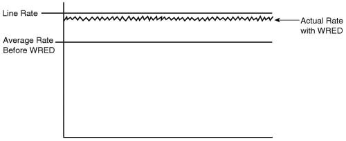
First, RED measures the average queue depth of the queue in question. RED calculates the average depth, and then decides whether congestion is occurring based on the average depth. RED uses the average depth, and not the actual queue depth, because the actual queue depth will most likely change much more quickly than the average depth. Because RED wants to avoid the effects of synchronization, it needs to act in a balanced fashion, not a jerky, sporadic fashion. Figure 7-5 shows a graph of the actual queue depth for a particular queue, compared with the average queue depth.
As seen in the graph, the calculated average queue depth changes more slowly than does the actual queue depth. RED uses the following algorithm when calculating the average queue depth:
![]()
For you test takers out there, do not worry about memorizing the formula, but focus on the idea. WRED uses this algorithm, with a default for n of 9. This makes the equation read as follows:
![]()
In other words, the current queue depth only accounts for .2 percent of the new average each time it is calculated. Therefore, the average changes slowly, which helps RED prevent overreaction to changes in the queue depth. When configuring WRED, you can change the value of n in this formula by setting the exponential weighting constant parameter. By making the exponential weighting constant smaller, you make the average change more quickly; by making it larger, the average changes more slowly.
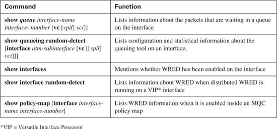
RED decides whether to discard packets by comparing the average queue depth to two thresholds, called the minimum threshold and maximum threshold. Table 7-2 describes the overall logic of when RED discards packets, as illustrated in Figure 7-6.
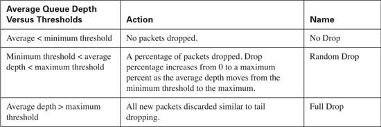
When the average queue depth is very low or very high, the actions are somewhat obvious. As seen in Table 7-2 and Figure 7-6, RED does not discard packets when the average queue depth falls below the minimum threshold. When the average depth rises above the maximum threshold, RED discards all packets. While this action might seem like a Tail Drop action, technically it is not, because the actual queue might not be full yet. So, to distinguish between true Tail Drop, and the case when the RED average queue depth exceeds the maximum threshold, RED calls this action category Full Drop.
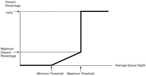
In between the two thresholds, however, RED discards a percentage of packets, with the percentage growing linearly as the average queue depth grows. The core concept behind RED becomes more obvious if you notice that the maximum percentage of packets discarded is still much less than discarding all packets. Once again, RED wants to discard some packets, but not all packets. As congestion increases, RED discards a higher percentage of packets. Eventually, the congestion can increase to the point that RED discards all packets.
You can set the maximum percentage of packets discarded by WRED by setting the mark probability denominator (MPD) setting in IOS. IOS calculates the maximum percentage using the formula 1/MPD. For instance, an MPD of 10 yields a calculated value of 1/10, meaning the maximum discard rate is 10 percent.
RED discards a larger percentage of packets as the average queue depth approaches the maximum threshold, as shown in the graph of Figure 7-6. RED also randomly picks the packets that will be discarded.

The next two sections in this chapter cover WRED and ECN, including their respective configurations.
WRED behaves almost identically to RED, as described in the preceding section of this chapter. It calculates the average queue depth, and decides whether to discard packets, and what percentage of packets to discard, based on all the same variables as RED.
The difference between RED and WRED lies in the fact that WRED creates a WRED profile for each precedence or DSCP value. A WRED profile is a set of minimum and maximum thresholds plus a packet discard percentage. The minimum and maximum thresholds are defined as a number of entries in the queue. Instead of directly configuring the discard percentage, you configure the Mark Probability Denominator (MPD), with the percentage being 1/MPD. By using a different WRED profile for each IP Precedence or DSCP value, WRED can treat packets differently.
The other major concept that needs to be covered, before diving into WRED configuration, relates to where WRED can be enabled, and how it interoperates with queuing tools. Interestingly, although WRED can be enabled on a physicalinterface, it cannot be concurrently enabled along with any other queuing tool! When using Modular QoS command-line interface (MQC) to configure queuing, however, WRED can be used for individual class queues.
The following sections cover the following:
![]() How WRED weights packets
How WRED weights packets
![]() When WRED can be enabled
When WRED can be enabled
![]() When WRED can be enabled to work with other queuing tools
When WRED can be enabled to work with other queuing tools
![]() WRED configuration
WRED configuration
WRED bases its decisions about when to discard packets, and what percentage to discard, on the following four factors:
![]() The average queue depth
The average queue depth
![]() The minimum threshold
The minimum threshold
![]() The maximum threshold
The maximum threshold
![]() The MPD
The MPD
First, just like RED, WRED calculates the average queue depth. WRED then compares the average queue depth to the minimum and maximum thresholds to decide whether it should discard packets. If the average queue depth is between the two thresholds, WRED discards a percentage of the packets, with the percentage based on the MPD; if the average queue depth exceeds the maximum threshold, WRED discards all new packets.
To weight based on precedence or DSCP markings, WRED sets the minimum threshold, maximum threshold, and the MPD to different values per precedence or DSCP value. The average queue depth calculation, however, is not based on the precedence or DSCP value, but is instead calculated for all packets in the queue, regardless of the precedence or DSCP value.
An example of how WRED weights packets can help you make more sense out of how WRED behaves differently than RED. First, consider Figure 7-7, which happens to show the default settings for precedence 0; these settings together define the WRED profile for Precedence 0 traffic.

WRED calculates the average queue depth just like RED, ignoring precedence, but it decides when to discard packets based on the precedence or DSCP value. Suppose, for instance, that the average queue depth just passed 20. For new precedence 0 packets that need to be placed into the queue, WRED begins discarding some packets. If the average queue depth continues to increase toward 40, WRED continues to discard precedence 0 packets, but more aggressively, up to a rate of 10 percent, when the average queue depth reaches 40. After the average queue depth passes 40, WRED discards all new precedence 0 packets. In fact, if all packets were precedence 0, RED and WRED would behave identically.
The real differences between RED and WRED can be seen with more than one IP precedence value. Figure 7-8 shows the WRED profile for both precedence 0 and precedence 3. (The settings in the figure do not match WRED’s precedence 3 defaults, which are listed later in this section.)

Suppose that the queue associated with the interface has a bunch of packets in it, marked with different precedence values, and the average queue depth just passed 20. For new precedence 0 packets that need to be placed into the queue, WRED begins discarding some precedence 0 packets, because the minimum threshold for precedence 0 is 20. WRED does not discard any precedence 3 packets, however, because the precedence 3 minimum threshold is 30. After the average queue depth reaches 30, WRED starts discarding precedence 3 packets as well. As the average queue depth reaches 40, precedence 0 packets are discarded at a rate approaching 10 percent, but precedence 3 packets are only discarded 5 percent of the time, because the MPD is set to 20, and 1/20 is 5 percent. With these two WRED profiles, WRED discards precedence 0 packets earlier, and at a higher rate, as compared to precedence 3 packets. In short, the weighting feature of WRED just determines when WRED begins discarding a percentage of the packets (per-precedence minimum threshold), the maximum percentage discarded (based on per-precedence MPD), and the point at which WRED discards all packets of that precedence (based on the per-precedence maximum threshold).
IOS uses logical choices for the default settings for all WRED parameters. However, you can choose to override the parameters with configuration commands. Tables 7-4 and 7-5 list the IOS default values for minimum threshold, maximum threshold, and MPD with precedence-based WRED (Table 7-4) and DSCP-based WRED (Table 7-5).


Table 7-5 Cisco IOS Software Default WRED Profiles for DSCP-Based WRED*

* Stated Values for IOS 12.2 Mainline Software
** Class selector DSCP values use the same WRED profile settings as their corresponding precedence values.
Cisco IOS Software follows the suggested meaning of all DSCP values, including the fact that these four AF DSCP values should be given equal treatment. The last digit of the name of the AF DSCP value identifies the drop preference, with 3 being most likely to be dropped, and 1 being least likely to be dropped. Note, for instance, that the settings for assured forwarding (AF) DSCPs AF11, AF21, AF31, and AF41 are all identical. For the same reason, AF12, AF22, AF32, and AF42 have the same defaults, as do AF13, AF23, AF33, and AF43.
WRED relies on the average queue depth concept, which calculates a rolling average of the queue depth of some queue. But which queue? Well, first consider a serial interface on a router, on which Weighted Fair Queuing (WFQ) is enabled by default. In this case, however, WFQ has been disabled, leaving a single first-in, first-out (FIFO) output queue on the interface. Figure 7-9 shows the basic idea.

As was covered in depth in Chapter 5, “Congestion Management,” each interface has a TX Queue or TX Ring. If the TX Ring/TX Queue fills, IOS places new packets into the software queue(s) awaiting transmission. In this example, a single FIFO output queue is used, as shown. With WRED also enabled, WRED calculates the average queue depth of the single FIFO output queue. As new packets arrive, before being placed into the FIFO output queue, WRED logic decides whether the packet should be discarded, as described in detail earlier in this chapter.
With WRED enabled directly on a physical interface, IOS supports FIFO Queuing, and FIFO Queuing only! That fact certainly makes the explanation easier, because there is less to cover! So, WRED works just like Figure 6-9 when it is enabled directly on a physical interface, because WRED can only work with a single FIFO queue in that case.
You might recall that of all the queuing tools listed in Chapter 5, CBWFQ and Low Latency Queuing (LLQ, which is merely a variation of CBFWQ) are the only queuing tools that claim to be capable of using WRED. To use WRED with CBWFQ or LLQ, you need to configure CBWFQ or LLQ as you normally would, and then enable WRED inside the individual classes as needed. However, you cannot enable WRED inside a class configured as the low-latency queue (in other words, you cannot use WRED in a class that uses the priority command.) Figure 7-10 illustrates an expanded diagram of CBWFQ, with the details that include WRED’s part of the process.

As you recall, CBWFQ classifies traffic into various classes. Each class has a single FIFO queue inside the class, so WRED bases its average queue depth calculation on the actual depth of each per-class FIFO queue, respectively. In other words, a different instance of WRED operates on each of the FIFO queues in each class. WRED might be discarding packets aggressively in one congested class, without discarding any packets in a class that is not congested.
WRED can be enabled for some CBWFQ classes, and not for others. For instance, with LLQ, voice traffic is typically placed into the priority queue. Because voice is drop sensitive, and UDP based, it would be better not to just apply WRED to the voice class. Instead, you can apply WRED to the data classes that serve predominantly TCP flows. This way, WRED can be used to limit the queue congestion for the interface without performing drops on the voice traffic.
Now that you understand the basic operation of WRED, along with the meaning of the parameters that can be tuned, you can configure WRED.
WRED requires very little configuration if you want to take the IOS defaults for the various tunable settings, such as per-precedence and per-DSCP thresholds. If you want to change the defaults, the configuration details can become quite large.
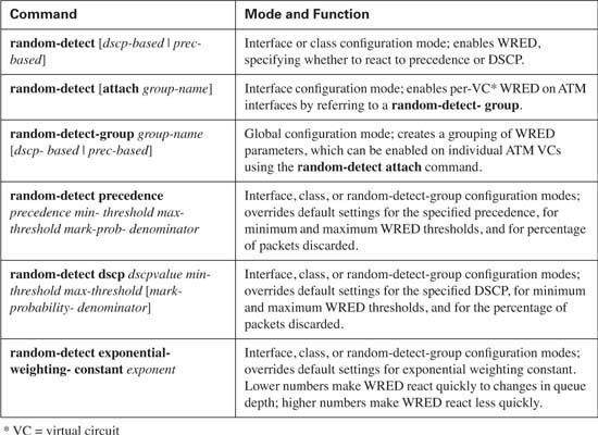
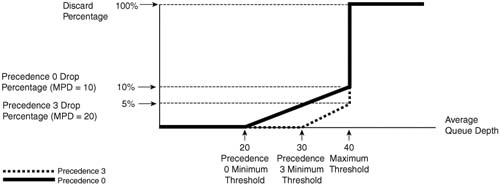
This section begins with a table of configuration commands (Table 7-6) and show commands (Table 7-7), followed by three separate examples.
In the first example, R3 enables WRED on its S0/0 interface. WRED treats packets differently based on the IP precedence value, which has been marked with CB marking as the packets enter R3’s E0/0 interface. The marking logic performed by CB marking is as follows:
![]() VoIP payload: DSCP EF
VoIP payload: DSCP EF
![]() HTTP traffic for web pages with “important” in the URL: DSCP AF21
HTTP traffic for web pages with “important” in the URL: DSCP AF21
![]() HTTP traffic for web pages with “not-so” in the URL: DSCP AF23
HTTP traffic for web pages with “not-so” in the URL: DSCP AF23
![]() All other: DSCP default
All other: DSCP default
To generate traffic in this network, two voice calls will be made between the analog phones attached to R1 and R4. Multiple web browsers will load the standard page (this is the same page we have used in other chapters in this book) with two TCP connections created by each browser—one to get a file with the word “important” in it, and the other getting a file with “not-so” in it. An FTP download of a large file will also be initiated from the Server to Client1.
Example 7-1 shows the basic configuration and show commands output. Only the required commands and parameters have been used, with defaults for all other settings. The example uses the familiar network diagram, as repeated in Figure 7-11.

Example 7-11 WRED Default Configuration, R3, S0/0
!
hostname R3
!
no ip domain-lookup
ip host r2 192.168.23.252
ip host r1 192.168.1.251
!
ip cef
!
match ip rtp 16384 16383
class-map match-all http-impo
match protocol http url "*important*"
class-map match-all http-not
match protocol http url "*not-so*"
class-map match-all class-default
match any
!
class voip-rtp
set ip dscp ef
class http-impo
set ip dscp af21
class http-not
set ip dscp af23
class class-default
set ip dscp default
call rsvp-sync
!
interface Ethernet0/0
description connected to SW2, where Server1 is connected
ip address 192.168.3.253 255.255.255.0
half-duplex
interface Serial0/0
description connected to FRS port S0. Single PVC to R1.
no ip address
encapsulation frame-relay
load-interval 30
!
interface Serial0/0.1 point-to-point
description point-point subint global DLCI 103, connected via PVC to DLCI 101 (
R1)
ip address 192.168.2.253 255.255.255.0
frame-relay interface-dlci 101
! Lines omitted for brevity.
!
Interface Serial0/0 queueing strategy: random early detection (WRED)
Exp-weight-constant: 9 (1/512)

R3#show queue s 0/0
Packet 1, linktype: ip, length: 64, flags: 0x88
source: 192.168.3.254, destination: 192.168.2.251, id: 0x053E, ttl: 253,
TOS: 184 prot: 17, source port 18378, destination port 17260
data: 0x47CA 0x436C 0x0028 0x0000 0x8012 0x3F73 0x4C7E
0x8D44 0x18D1 0x03FE 0xFC77 0xA2A7 0x35A2 0x54E7
Packet 2, linktype: ip, length: 64, flags: 0x88
source: 192.168.3.254, destination: 192.168.2.251, id: 0x0545, ttl: 253,
TOS: 184 prot: 17, source port 16640, destination port 17178
data: 0x4100 0x431A 0x0028 0x0000 0x8012 0x6330 0x21B4
0x82AF 0x05C9 0x03FE 0x1448 0x8706 0xAFD9 0xD364
!
! Output omitted for brevity.
!
R3#show interfaces s 0/0
Serial0/0 is up, line protocol is up
Hardware is PowerQUICC Serial
Description: connected to FRS port S0. Single PVC to R1.
MTU 1500 bytes, BW 1544 Kbit, DLY 20000 usec,
reliability 255/255, txload 20/255, rxload 4/255
Encapsulation FRAME-RELAY, loopback not set
Keepalive set (10 sec)
LMI enq sent 591, LMI stat recvd 591, LMI upd recvd 0, DTE LMI up
LMI DLCI 1023 LMI type is CISCO frame relay DTE
FR SVC disabled, LAPF state down
Broadcast queue 0/64, broadcasts sent/dropped 2726/0, interface broadcasts 252
2
Last input 00:00:02, output 00:00:00, output hang never
Last clearing of "show interface" counters 01:38:28
Input queue: 0/75/0/0 (size/max/drops/flushes); Total output drops: 4391
30 second output rate 122000 bits/sec, 91 packets/sec
23863 packets input, 1535433 bytes, 0 no buffer
Received 0 broadcasts, 0 runts, 0 giants, 0 throttles
2 input errors, 0 CRC, 2 frame, 0 overrun, 0 ignored, 0 abort
36688 packets output, 5638653 bytes, 0 underruns
0 output errors, 0 collisions, 4 interface resets
0 output buffer failures, 0 output buffers swapped out
0 carrier transitions
DCD=up DSR=up DTR=up RTS=up CTS=up
The WRED part of the configuration is quite short. The configuration shows the random-detect interface subcommand under serial 0/0. As you will see later, the command actually disables WFQ if configured. The rest of the highlighted configuration commands show the CB marking configuration, which implements the functions listed before the example. (For more information about CB marking, see Chapter 4, “Classification and Marking.”)
After the configuration, the show queueing interface serial 0/0 command output lists the WRED settings, and the statistics for each precedence value. The defaults for the exponential weighting constant, and the per-precedence defaults of minimum threshold, maximum threshold, and MPD are all listed. In addition, the command lists statistics for bytes/packets dropped by WRED, per precedence value. For those of you who did not memorize the DSCP values, you may not be able to correlate the DSCP values set by CB marking, and the precedence values interpreted by WRED. WRED just looks at the first 3 bits of the IP ToS byte when performing precedence-based WRED. So, DSCP best effort (BE) equates to precedence 0, DSCP AF21 and AF23 both equate to precedence 2, and DSCP expedited forwarding (EF) equates to precedence 5.
The show queueing command also lists a column of statistics for tail drop as well as random drops. In this example, WRED has dropped several packets, and the queue has filled, causing tail drops, as shown with the nonzero counters for random drops and tail drops in the show queueing command output.
The show queue serial 0/0 command lists the same type of information seen in earlier chapters. However, this command lists one particularly interesting item relating to WRED in the first line of the command output. The actual queue depth for the single FIFO queue used with WRED is listed at 57 entries in this particular example. The earlier show queueing command lists an average queue depth of 37 just instants before. These two numbers just give us a small reminder that WRED decides to drop based on average queue depth, as opposed to actual queue depth.
Finally, the show interfaces command at the end of the example reminds us that WRED does not work with any other queuing method directly on the interface. The command uses the statement “Queueing strategy: random early detection (RED)” to remind us of that fact. WRED uses a single FIFO queue, and measures its average queue depth based on the queue depth of the FIFO queue.
The second WRED configuration example uses WRED on R3’s S0/0 interface again, but this time with DSCP WRED, and a few changes to the defaults. In fact, Example 7-2 just shows the changed configuration, with most of the configuration staying the same. For instance, the same CB marking configuration is used to mark the traffic, so the details are not repeated in the example. The example uses the familiar network diagram that was also used in the preceding example.
Example 7-12 DSCP-Based WRED on R3 S0/0
Enter configuration commands, one per line. End with CNTL/Z.
R3(config)#interface serial 0/0
R3(config-if)#random-detect dscp-based
R3(config-if)#random-detect dscp af21 50 60
R3(config-if)#random-detect dscp af23 20 30
R3(config-if)#random-detect ?
dscp parameters for each dscp value
dscp-based Enable dscp based WRED on an interface
exponential-weighting-constant weight for mean queue depth calculation
flow enable flow based WRED
prec-based Enable prec based WRED on an interface
precedence parameters for each precedence value
<cr>
R3(config-if)#random-detect exponential-weighting-constant 5
R3(config-if)#^Z
R3#show queue serial 0/0
Packet 1, linktype: ip, length: 64, flags: 0x88
source: 192.168.3.254, destination: 192.168.2.251, id: 0x0545, ttl: 253,
TOS: 184 prot: 17, source port 16640, destination port 17178
data: 0x4100 0x431A 0x0028 0x0000 0x8012 0xAB15 0x21E1
0x71CF 0x05C9 0x03FE 0x7AA3 0x770B 0x2408 0x8264
Packet 2, linktype: ip, length: 64, flags: 0x88
source: 192.168.3.254, destination: 192.168.2.251, id: 0x053E, ttl: 253,
data: 0x47CA 0x436C 0x0028 0x0000 0x8012 0x8759 0x4CAB
0x7D04 0x18D1 0x03FE 0xDC15 0x3E4A 0x4E92 0x5447
R3#show queueing interface s 0/0
Interface Serial0/0 queueing strategy: random early detection (WRED)
Mean queue depth: 38

The configuration begins with a change from precedence-based WRED to DSCP-based WRED using the random-detect dscp-based interface subcommand. The random-detect dscp af21 50 60 changes the default minimum and maximum thresholds for AF21 to 50 and 60, respectively, with the random-detect dscp af23 20 30 changing these same values for AF23. In addition, although Cisco does not recommend changing the exponential weighting constant, the configuration does offer an example of the syntax with the random-detect exponential- weighting-constant 5 command. By setting it to a smaller number than the default (9), WRED will more quickly change the average queue depth calculation, more quickly reacting to changes in the queue depth.
The command output from the various show commands do not differ much compared to when DSCP-based WRED is enabled. The format now includes DSCP values rather than precedence values, as you may notice with the counters that point out drops for both AF21 and AF23, which were previously both treated as precedence 2.
WRED suffers from the lack of concurrent queuing tool support on an interface. However, WRED can be enabled inside a CBWFQ class, operating on the queue for the class, effectively enabling WRED concurrently with CBWFQ. The final WRED example shows a configuration for WRED using LLQ.
The last WRED configuration example repeats base configuration similar to one of the CBWFQ examples from Chapter 5. Voice, HTTP, and FTP traffic compete for the same bandwidth, with WRED applied per-class for the two HTTP classes and one FTP class. Note that because voice traffic is drop sensitive, WRED is not enabled for the low-latency queue. Because WRED can be enabled per class in conjunction with CBWFQ, WRED calculates average queue depth based on the per-class queue.
The criteria for each type of traffic is as follows:
![]() R3’s S0/0 is clocked at 128 kbps.
R3’s S0/0 is clocked at 128 kbps.
![]() VoIP payload is marked with DSCP EF using CB marking on ingress to R3 E0/0. On egress of R3’s S0/0 interface, DSCP EF traffic is placed in its own queue, without WRED. This class gets 58 kbps.
VoIP payload is marked with DSCP EF using CB marking on ingress to R3 E0/0. On egress of R3’s S0/0 interface, DSCP EF traffic is placed in its own queue, without WRED. This class gets 58 kbps.
![]() Any HTTP traffic whose URL contains the string “important” anywhere in the URL is marked with AF21 using CB marking on ingress to R3 E0/0. On egress of R3’s S0/0 interface, DSCP AF21 traffic is placed in its own queue, with WRED. This class gets 20 kbps.
Any HTTP traffic whose URL contains the string “important” anywhere in the URL is marked with AF21 using CB marking on ingress to R3 E0/0. On egress of R3’s S0/0 interface, DSCP AF21 traffic is placed in its own queue, with WRED. This class gets 20 kbps.
![]() Any HTTP traffic whose URL contains the string “not-so” anywhere in the URL is marked with AF23 using CB marking on ingress to R3 E0/0. On egress of R3’s S0/0 interface, DSCP AF23 traffic is placed in its own queue, with WRED. This class gets 8 kbps.
Any HTTP traffic whose URL contains the string “not-so” anywhere in the URL is marked with AF23 using CB marking on ingress to R3 E0/0. On egress of R3’s S0/0 interface, DSCP AF23 traffic is placed in its own queue, with WRED. This class gets 8 kbps.
![]() All other traffic is marked with DSCP BE using CB marking on ingress to R3 E0/0. On egress of R3’s S0/0 interface, DSCP BE traffic is placed in its own queue, with WRED. This class gets 20 kbps.
All other traffic is marked with DSCP BE using CB marking on ingress to R3 E0/0. On egress of R3’s S0/0 interface, DSCP BE traffic is placed in its own queue, with WRED. This class gets 20 kbps.
Example 7-3 lists the configuration and show commands used when WRED is enabled in LLQ classes dscp-af21, dscp-af23, and class-default.
Example 7-13 WRED Used in LLQ Classes dscp-af21, dscp-af23, and class-default
Building configuration...
!
!Portions omitted for brevity
!
!
! The following classes are used in the LLQ configuration applied to S0/0
!
class-map match-all dscp-ef
match ip dscp ef
class-map match-all dscp-af21
match ip dscp af21
class-map match-all dscp-af23
match ip dscp af23
!
! The following classes are used on ingress for CB marking
!
class-map match-all http-impo
match protocol http url "*important*"
class-map match-all http-not
match protocol http url "*not-so*"
class-map match-all class-default
match any
class-map match-all voip-rtp
match ip rtp 16384 16383
!
! Policy-map laundry-list creates CB marking configuration, used on
! ingress on E0/0
!
policy-map laundry-list
class voip-rtp
set ip dscp ef
class http-impo
set ip dscp af21
class http-not
set ip dscp af23
class class-default
set ip dscp default
!
! Policy-map queue-on-dscp creates LLQ configuration, with WRED
! inside three classes
!
priority 58
class dscp-af23
class class-default
interface Ethernet0/0
description connected to SW2, where Server1 is connected
ip address 192.168.3.253 255.255.255.0
ip nbar protocol-discovery
half-duplex
service-policy input laundry-list
!
interface Serial0/0
description connected to FRS port S0. Single PVC to R1.
bandwidth 128
no ip address
encapsulation frame-relay
load-interval 30
max-reserved-bandwidth 85
!
interface Serial0/0.1 point-to-point
description point-point subint global DLCI 103, connected via PVC to DLCI 101 (R1)
ip address 192.168.2.253 255.255.255.0
frame-relay interface-dlci 101
!
R3#show policy-map interface serial 0/0
Serial0/0
Service-policy output: queue-on-dscp
Class-map: dscp-ef (match-all)
46437 packets, 2971968 bytes
30 second offered rate 0 bps, drop rate 0 bps
Match: ip dscp ef
Weighted Fair Queueing
Strict Priority
Output Queue: Conversation 264
Bandwidth 58 (kbps) Burst 1450 (Bytes)
(pkts matched/bytes matched) 42805/2739520
Class-map: dscp-af21 (match-all)
2878 packets, 3478830 bytes
Match: ip dscp af21
Weighted Fair Queueing
Output Queue: Conversation 266
Bandwidth 20 (kbps)
(pkts matched/bytes matched) 2889/3494718
exponential weight: 9
mean queue depth: 5

Class-map: dscp-af23 (match-all)
1034 packets, 1250984 bytes
30 second offered rate 32000 bps, drop rate 0 bps
Match: ip dscp af23
Weighted Fair Queueing
Output Queue: Conversation 267
Bandwidth 8 (kbps)
(pkts matched/bytes matched) 1047/1266140
exponential weight: 9


The example lists a large configuration, but only a small amount pertains to WRED. Two sets of class maps have been configured—one set is used by the CB marking policy called laundry-list, and the other set is used by the LLQ policy map called queue-on-dscp. In policy-map queue-on-dscp, inside classes dscp-af21, dscp-af23, and class-default, the random-detect dscp-based command enables WRED. These three random-detect commands are highlighted in the show running-config output in the example.
Also note that WRED is not enabled on interface serial 0/0 in this configuration, because WRED applies to the output queues used by each class. Because WRED is not enabled on the main interface, to see statistics for WRED, you must use the show policy-map interface command. This command in the example lists WRED statistics inside each class in which WRED has been enabled. For the classes in which WRED is not enabled, such as the dscp-ef class, no additional WRED statistical information is listed. The default values for exponential weighting constant, and the per-DSCP defaults for minimum threshold, maximum threshold, and MPD are all listed in the command output.
WRED provides a valuable tool for managing congestion in queues. Cisco IOS uses defaults that conform to the DiffServ Assured Forwarding conventions, which reduce the likelihood that you will need to configure thresholds for WRED. WRED can be particularly effective when used with MQC-based queuing tools, but when enabled directly on an interface, WRED has the unfortunate side effect of disallowing other queuing tools to be used. Table 7-8 lists some of WRED’s key points.

ECN is very much interrelated with WRED. This section begins with a description of how ECN works with WRED, followed by a short section on ECN configuration.
WRED’s main goal is to get some TCP senders to temporarily slow down the rate at which they send data into the network. By doing so, the temporary congestion may abate, avoiding problems such as tail drop and global synchronization. However, to cause TCP senders to slow down, WRED resorts to an inherently harmful action—the discarding of packets. It’s a classic case of doing some harm now, in order to prevent more harm later.
Explicit Congestion Notification (ECN) provides the same benefit as WRED, without discarding packets. In fact, ECN is really just a feature of WRED in which TCP senders are signaled to slow down by setting bits in the packet headers. By signaling TCP senders to slow down, congestion may abate, all the while avoiding the use of packet drop.
When ECN is enabled, a router’s WRED logic works almost exactly as before. For instance, WRED profiles are defined for each precedence or DSCP value. Average queue depths are calculated. WRED compares the average queue depth with the thresholds, and decides whether to drop nothing, to randomly drop a percentage of the packets, or to perform full drop.
The difference lies in what WRED does once it randomly chooses a packet to be discarded, which happens when the average queue depth is between the minimum and maximum threshold. With ECN enabled, WRED still randomly picks the packet, but instead of discarding it, WRED marks a couple of bits in the packet header, and forwards the packet. Marking these bits begins a process, defined in RFC 3168, which causes the sender of the TCP segment to reduce the congestion window (CWND) by 50 percent.
ECN causes the sender of the randomly-chosen packet to slow down. To do so, the sender of the packet must be told that congestion occurred, and ECN wants it to slow down. To trigger the process, the router, which notices the congestion, needs some bits to set in order to signal that the packet experienced congestion. Figure 7-12 shows the bits that are set by the router.

You might recall from back in Chapter 2, “QoS Tools and Architectures,” that the two low-order bits in the DSCP byte were formerly unused, but they were later defined for use by ECN. With RFC 3168, which defines ECN, the two extra bits have been defined as the ECT and CE bits—together known as the ECN field.
To see how these bits are used, Figure 7-13 shows a full example. When looking at the figure, and the explanation that follows, keep in mind these two important points:

![]() Routers, not the TCP endpoints, notice congestion, and then want to get the TCP senders to slow down.
Routers, not the TCP endpoints, notice congestion, and then want to get the TCP senders to slow down.
![]() TCP senders must somehow learn that a router is congested, so it can choose to slow down.
TCP senders must somehow learn that a router is congested, so it can choose to slow down.
While Figure 7-13 holds several details, the general idea is that the router sets some bits in the packet instead of discarding it. In order to get the original sender of the packet to slow down, bits need to be set in the next packet sent back to the original sender. In other words, the router can set bits in the packet flowing left-to-right in the figure, but some other bits must be set in the packet flowing in the opposite direction (right-to-left) in order for PC Client2 to know to slow down.
The following steps explain the contents of Figure 7-13, with the text following the circled numbers in the figure:
1. A TCP sender has negotiated a TCP connection, and both endpoints agree that they can support ECN. To indicate that support, the TCP sender sets the ECN bits to either 01 or 10. (If a TCP sender does not support ECN, the bits should be set to 00.)
2. The router uses WRED to recognize congestion, and the router randomly chooses this packet for discard. However, with ECN configured, the router checks the packet’s ECN bits, and finds them set to “01”. So, the router sets the bits to “11”, and forwards the packet instead of discarding it.
3. The packet continues on its trip to the TCP receiver.
4. The TCP receiver receives the packet, and notices ECN = 11. As a result, the receiver sets a TCP flag in the next TCP segment it sends back to the TCP sender. The flag is called the Explicit Congestion Experienced (ECE) flag. (The ECN bit settings are not important in the packet at step 4, but they can be used to signal congestion in the right-to-left direction in this example.)
5. The packet passes through the router just like any other packet—there is no need for the router to watch for this return packet, or to set any other bits at this point.
6. The TCP sender receives the TCP segment with TCP ECE flag set, telling it to slow down. So, the TCP sender reduces its congestion window (CWND) by half.
7. The TCP sender wants the TCP receiver to know that it “got the message” and slowed down. To do so, the TCP sender, in it’s next TCP segment, sets another new TCP flag called the Congestion Window Reduced (CWR) flag.
As you can see, the sender does indeed slow down by reducing its CWND, and the router didn’t have to discard any packets. Overall, it’s a better solution than WRED without ECN. However, this process depends on whether the TCP implementations on the endpoint hosts supports ECN or not. For instance, if Client2 and Server1 had negotiated about ECN when initializing the TCP connection, and one of them didn’t support ECN, they would decide not to use ECN. Packets sent for this TCP connection would set ECN = 00. Under these circumstances, even with ECN configured on the router, the router’s WRED logic could still discard the packet. That’s because the router’s ECN logic first checks to see whether ECN is supported for the underlying TCP connection; if not supported, the router uses the same old WRED logic, and discards the packet.
In summary, the WRED ECN logic works just like WRED without ECN, until a packet has been randomly chosen for discard (when average queue depth is between the min and max thresholds). At that point:
If ECN = 00, discard the packet
Otherwise, set ECN = 11, and forward the packet.
As you can understand from the details, ECN relies on routers that can mark the ECN bits, as well as IP hosts that support ECN with their TCP implementations. Implementation on Cisco routers is relatively easy, with one additional command required for configuration as compared with WRED configuration. Example 7-4 lists a simple WRED configuration, with ECN enabled, along with a few show commands.
Example 7-14 WRED Used in LLQ Classes dscp-af21, dscp-af23, and class-default
Building configuration...
!
!Portions omitted for brevity
!
ip cef
!
match protocol http
bandwidth percent 50
random-detect dscp-based
!
interface Serial0/0
no ip address
clockrate 128000
!
interface Serial0/0.1 point-to-point
bandwidth 128
ip address 192.168.2.3 255.255.255.0
frame-relay interface-dlci 143
!
! The rest has been omitted for brevity
!
R3#show policy-map interface s0/0
Serial0/0
Service-policy output: ecn-test
Class-map: class1 (match-all)
0 packets, 0 bytes
5 minute offered rate 0 bps, drop rate 0 bps
Match: protocol http
Queueing
Output Queue: Conversation 265
Bandwidth 50 (%)
Bandwidth 772 (kbps)
(pkts matched/bytes matched) 0/0
(depth/total drops/no-buffer drops) 0/0/0
exponential weight: 9
dscp Transmitted Random drop Tail drop Minimum Maximum Mark
pkts/bytes pkts/bytes pkts/bytes thresh thresh prob
af11 0/0 0/0 0/0 32 40 1/10
af12 0/0 0/0 0/0 28 40 1/10
af13 0/0 0/0 0/0 24 40 1/10
af21 0/0 0/0 0/0 32 40 1/10
af22 0/0 0/0 0/0 28 40 1/10
af23 0/0 0/0 0/0 24 40 1/10
af32 0/0 0/0 0/0 28 40 1/10
af33 0/0 0/0 0/0 24 40 1/10
af41 0/0 0/0 0/0 32 40 1/10
af42 0/0 0/0 0/0 28 40 1/10
af43 0/0 0/0 0/0 24 40 1/10
cs1 0/0 0/0 0/0 22 40 1/10
cs2 0/0 0/0 0/0 24 40 1/10
cs3 0/0 0/0 0/0 26 40 1/10
cs4 0/0 0/0 0/0 28 40 1/10
cs5 0/0 0/0 0/0 30 40 1/10
cs6 0/0 0/0 0/0 32 40 1/10
cs7 0/0 0/0 0/0 34 40 1/10
ef 0/0 0/0 0/0 36 40 1/10
rsvp 0/0 0/0 0/0 36 40 1/10
default 0/0 0/0 0/0 20 40 1/10
dscp ECN Mark
pkts/bytes
af12 0/0
af13 0/0
af21 0/0
af22 0/0
af23 0/0
af31 0/0
af32 0/0
af33 0/0
af41 0/0
af42 0/0
af43 0/0
cs1 0/0
cs2 0/0
cs3 0/0
cs4 0/0
cs5 0/0
cs6 0/0
cs7 0/0
ef 0/0
rsvp 0/0
default 0/0
Class-map: class-default (match-any)
0 packets, 0 bytes
5 minute offered rate 0 bps, drop rate 0 bps
Match: any
The configuration is indeed quite simple. Notice the inclusion of the random-detect ecn command inside policy-map ecn-test. The rest of the configuration looks like normal CBWFQ configuration, with WRED enabled. Remember, ECN is really just a feature of WRED, with the same details of WRED thresholds and discard percentages, per DSCP. ECN simply means that if WRED randomly chooses to discard a packet, if that packet supports ECN (ECN field is 01 or 10), then the router marks ECN=11, and doesn’t discard it.
Note that the ECN logic also means that randomly-chosen packets that have ECN set as 00 will be discarded like WRED normally would. So, the WRED section of the show policy-map interface s0/0 command has the same types of statistics for discarded packets. A separate new section of output is included later to count the number of packets marked with ECN = 11. The new section is denoted with a heading in gray background near the end of the example.
The “Foundation Summary” is a collection of tables and figures that provide a convenient review of many key concepts in this chapter. For those of you already comfortable with the topics in this chapter, this summary could help you recall a few details. For those of you who just read this chapter, this review should help solidify some key facts. For any of you doing your final prep before the exam, these tables and figures are a convenient way to review the day before the exam.
Figure 7-14 shows a graph of CWND after packet loss just using slow start, and another with slow start plus congestion avoidance.

The key information about TCP and UDP operation when packets are dropped is summarized in the following list:
![]() UDP senders do not reduce or increase sending rates as a result of lost packets.
UDP senders do not reduce or increase sending rates as a result of lost packets.
![]() TCP senders do reduce their sending rates as a result of lost packets.
TCP senders do reduce their sending rates as a result of lost packets.
![]() TCP senders decide to use either the receiver window or the CWND, based on whichever is lower at the time.
TCP senders decide to use either the receiver window or the CWND, based on whichever is lower at the time.
![]() TCP slow start and congestion avoidance dictate how fast the CWND rises after the window was lowered due to packet loss.
TCP slow start and congestion avoidance dictate how fast the CWND rises after the window was lowered due to packet loss.
Table 7-9 describes the overall logic of when RED discards packets, with the same ideas outlined in Figure 7-15.

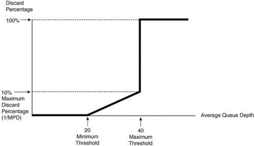
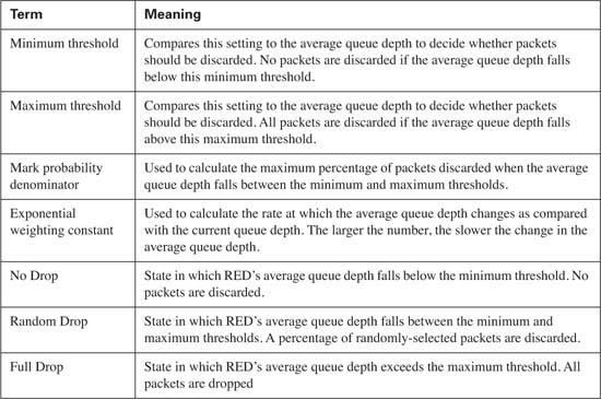
Table 7-10 summarizes some of the key terms related to RED.

Figure 7-16 shows the default WRED settings for precedence 0, with some nondefault settings for precedence 3 traffic.
WRED measures the average queue depth of the FIFO queue on an interface, as shown in Figure 7-17.

ECN allows WRED to signal a TCP sender to slow down, instead of discarding a packet sent by that TCP sender. Figure 7-18 shows the entire process.

As mentioned in the Introduction, you have two choices for review questions. The questions that follow next give you a more difficult challenge than the exam itself by using an open-ended question format. By reviewing now with this more difficult question format, you can exercise your memory better, and prove your conceptual and factual knowledge of this chapter. You can find the answers to these questions in Appendix A.
The second option for practice questions is to use the CD-ROM included with this book. It includes a testing engine and more than 200 multiple-choice questions. You should use this CD-ROM nearer to the end of your preparation, for practice with the actual exam format.
|
1. |
Describe the function of the congestion window in TCP, and how it is changed as a result of packet loss. |
|
2. |
Identify the two TCP windowing mechanisms, and describe when each is used. |
|
3. |
Describe the process of TCP slow start, and when it occurs. |
|
4. |
Describe the meaning of the term “global synchronization,” and discuss what causes it. |
|
5. |
Define the meaning of the term “tail drop.” |
|
6. |
Define the meaning of the term “TCP starvation.” |
|
7. |
Does RED compare the actual queue depth or the average queue depth to queue thresholds when deciding whether it should discard a packet? Why this one, and not the other? |
|
8. |
Describe how RED uses actual queue depth to calculate average queue depth. Do not list the formula, but just describe the general idea. |
|
9. |
Assume the RED minimum threshold is 20, the maximum threshold is 40, and the mark probability denominator is 10. What must be true for RED to discard all new packets? |
|
10. |
Assume the RED minimum threshold is 20, the maximum threshold is 40, and the mark probability denominator is 10. What must be true for RED to discard 5 percent of all new packets? |
|
11. |
Define how RED uses the mark probability denominator. Give one example. |
|
12. |
Define the term “exponential weighting constant.” If the value is lowered compared to the default setting of 9, how does RED behave differently? |
|
13. |
Define the term “WRED Profile.” |
|
14. |
Explain how you can tune how fast or slow that WRED changes the calculated average queue depth over time. |
|
15. |
Spell out the words represented by the initials RED, WRED, and FRED. |
|
16. |
List the three WRED terms that name the separate states in which WRED discards no packets, a percentage of packets, and all packets. |
|
17. |
List the queuing tools that can be concurrently supported on an interface when WRED has been enabled directly on a serial interface, assuming no retrictions on the particular model of router. |
|
18. |
Identify the most important difference between RED operation and WRED operation. |
|
19. |
Describe how WRED “weights” packets. |
|
20. |
List the queuing tools that can enable WRED for use with some or all of their queues, effectively enabling WRED concurrently with the queuing tool, assuming no retrictions on the particular model of router. |
|
21. |
What command enables you to look at WRED drop statistics when WRED is configured inside an MQC class? |
|
22. |
Taking as many defaults as possible, list the configuration commands needed to configure precedence-based WRED on interface S1/1. |
|
23. |
Taking as many defaults as possible, list the configuration commands needed to configure DSCP-based WRED on interface S1/1. |
|
24. |
Taking as many defaults as possible, list the configuration commands needed to configure DSCP-based WRED inside class class1, inside policy map my-policy. (You can assume that the CBWFQ configuration has already been completed, and you just entered global configuration mode. Assume that you need just to enable WRED in class class1.) |
|
25. |
List the command needed to set the minimum threshold to 25, the maximum threshold to 50, and the mark probability denominator to 4, for precedence 2. |
|
26. |
What show command lists detailed statistics about random drops on interface S1/1? |
|
27. |
For a single WRED profile, WRED can be either dropping no packets, randomly choosing packets to discard, or dropping all packets. For which of these three states does ECN impact WRED’s discard actions? How does it change what WRED does to the packets? |
|
28. |
Identify the bits in the IP header used with ECN, by name and location. |
|
29. |
Imagine a router on which WRED and ECN are enabled, and WRED decides to randomly discard a packet. What must be true in order for WRED to discard the packet, instead of using ECN logic to mark and forward the packet? Explain the role of any other devices besides the router. |
|
30. |
Imagine a router on which WRED and ECN are enabled, and WRED decides to randomly discard a packet. What must be true in order for WRED to use ECN logic to mark and forward the packet, instead of discarding the packet? Explain the role of any other devices besides the router. |
|
31. |
Imagine a policy map with WRED already configured for class class-web. What additional command is required to also enable ECN for the packets in that class? |