Chapter 12 Understanding Failover in FWSM
This chapter covers the concept of failover, its configurations, and redundancy in a Firewall Services Module (FWSM). Planning failure scenarios is always a good practice when designing a network solution. Redundancy for disaster recovery should always be a part of the network. Likewise, redundancy is also needed for firewalls.
Creating Redundancy in the FWSM
The two types of modes for redundancy in FWSM are as follows:
• Active/Standby mode
• Active/Active mode
The sections that follow cover the two modes in detail.
Understanding Active/Standby Mode
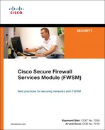
The firewall has an active unit and a nonactive unit. The active unit is called a primary firewall and the nonactive unit is called a secondary firewall. These two FWSM modules are symmetric to each other. All the traffic passes through the primary module and does not pass through the secondary module. The two symmetric modules can be in the same chassis or in a redundant Catalyst 65xx chassis. It is always a good practice to place firewalls in two separate chassis for full redundancy. This is a classic failover mode supported in firewalls. In multiple context mode, using Active/Standby mode, a primary FWSM is used and does not take advantage of redundant secondary FWSM unit for normal operations. For example, in multiple context mode, the FWSM is configured with two contexts: 1a and 2a in the primary FWSM and 1b and 2b in the secondary FWSM, as illustrated in Figure 12-1. For contexts 1a and 2a, the traffic flows only from the primary FWSM. The secondary FWSM will be in a standby mode. This failover mode does not split the traffic between primary and secondary units.
Figure 12-1 Understanding Active/Standby Mode
Understanding Active/Active Mode
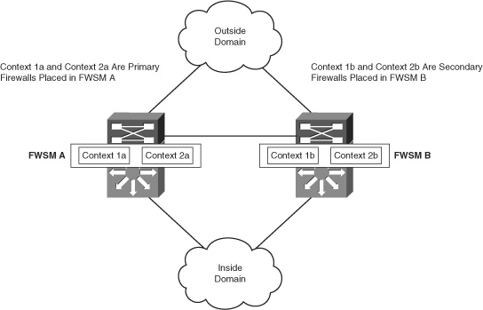
The Active/Active mode is applicable to the FWSM in multiple context mode and is supported in 3.1 release and later. The FWSM module can split the traffic between different contexts. The active context will be present in either the primary firewall or the secondary firewall. In this way, both the FWSM units will be passing traffic for different contexts. For example, in multiple context mode, two contexts are configured: 1a and 2a in FWSM 1 and 1b and 2b in FWSM 2, as illustrated in Figure 12-2. With multiple context mode, 1a is the primary firewall and 1b is the secondary firewall for context 1. The traffic for context 1 flows from the FWSM 1. The context 2 will have 2a as a standby firewall and 2b as a primary firewall. The traffic for context 2 flows from context 2b; that is, FWSM 2. In this way, the traffic is split between the two FWSM units using multiple context mode, and each FWSM will be a redundant pair for each other, based on the context.
Figure 12-2 Understanding Active/Active Mode
The IP address defined in the primary firewall is called the active IP address, and the IP address defined in the secondary firewall is called the standby IP address. The standby IP address must be in the same subnet as the active IP address. The requirement for the same IP subnet is to make failover work. There is no need for routing to identify the standby IP address subnet mask. The state link IP address and the MAC address do not change at failover. The secondary interfaces in the failover group that become active assume the MAC addresses and IP addresses of the primary interfaces in different security domains, after a failover. The interfaces for the failover function that is now in the standby state take over the standby MAC addresses and IP addresses.
In short, these sections cover two ways of enabling failover from a design perspective in an FWSM. The Active/Active mode can be used as a design advantage in multiple context mode. The traditional way of doing failover is still very prevalent for box-level redundancy.
Understanding Failover Link and State Link
Failover between two physical FWSMs is achieved through a failover link. Some of the important points for a failover link are as follows:
• Hellos and other messages for failover are exchanged between the primary and secondary FWSM units.
• The primary and the secondary FWSMs communicate to determine the operating status of each FWSM.
• When the primary unit fails, the failover takes place in the secondary unit. The state information of the active sessions is not copied to the secondary firewall.
• A VLAN interface needs to be configured in the FWSM. The VLAN must be configured in both the switches having FWSM modules and should carry the failover link information between the two switch chassis hosting the FWSMs.
The information exchanged through the failover link is as follows:
• State of the unit: Defines whether the unit is primary or secondary.
• Hello message: Keepalives for failover are sent via a failover link.
• Network link status: Describes the network link.
• MAC address exchange: Occurs during failover.
• Configuration replication and synchronization: Takes place from the primary to the secondary FWSM.
State link is needed for a stateful failover to function. Stateful failover for the FWSM enables the secondary firewall to continue processing and forwarding user sessions after a planned or unplanned outage. For this process, the entire state information is maintained between the primary and secondary FWSMs. State link maintains this communication, and it is configured with a failover link. The state link passes the state information of the active session from the primary FWSM to the secondary FWSM.
The state link is used to achieve stateful failover. It is required to have two separate VLANs for failover link and state link. In multiple context mode, both the failover and state links reside in the system context.
The stateful failover replicates the following types of traffic:
• TCP and User Datagram Protocol (UDP) connections
• Network Address Translation (NAT)
• Address Resolution Protocol (ARP) table
• Layer 2 bridge table (applicable for the firewall in transparent mode)
• GTP PDP connection database, where GTP is GPRS Tunneling Protocol and PDP is Packet Data Protocol
• Routing tables
• HTTP connection table (unless HTTP replication is enabled)
• User authentication (uauth) table
The common practice is to enable failover link and state link on any failover configuration. Always make sure the VLANs for both the links need to be separate. The physical connection between the two switch chassis for these VLANs should be separate from the regular traffic.
Requirements for Failover
The requirements and considerations needed to enable failover configuration in FWSM are as follows:
• System license requirements are needed for failover between two units.
• Both FWSMs should have the same software image.
• Both FWSMs should have the same interfaces, which is mandatory as a part of the configuration.
• It is a good practice to have the pair of FWSMs adjacent to all the Layer 2 interfaces. This will make the Layer 2 connections symmetric to both the FWSMs.
• To avoid loops in transparent mode, the failover configuration will need to allow BPDUs through the FWSM. This can be done using an EtherType access list.
Synchronizing the Primary and Secondary Firewalls
Configurations are synchronized from the active FWSM unit to the standby FWSM unit. The FWSM is configured with an initial set of commands for failover. The primary and secondary status for FWSM is defined in this initial set of commands (refer to Table 12-1 in the next section, “Monitoring Interfaces”). The FWSM becomes the primary firewall and its peer FWSM becomes the secondary or standby firewall, after enabling the initial set of failover commands. The standby FWSM will have failover commands, and the rest of the configurations are obtained from the primary FWSM. The secondary FWSM synchronizes with the primary FWSM. The synchronization can be triggered by the write standby command, which will copy the configuration from the primary FWSM to the secondary FWSM.
In multiple context mode, in a specific context in the primary FWSM, if write memory is executed, the primary FWSM copies the configuration to the secondary FWSM. The write memory must be executed per context level. Likewise, in the system context, if write memory all is executed, all the configurations from all the contexts are copied to the secondary FWSM. When using the write memory all command, it is not necessary to access each context for copying the configurations to the secondary FWSM.
Monitoring Interfaces
The FWSM determines the health of the primary and secondary firewalls by monitoring the failover link. When a unit does not receive hello messages on the failover link, the unit sends an ARP request to all interfaces, including the failover interface. Interfaces in different security domains can also be monitored in the FWSM. In multiple context mode, use the monitor command to monitor interfaces in different contexts. The maximum number of monitored interfaces on the FWSM is 250, divided among all contexts. The FWSM exchanges hellos after the failover configuration is completed between the primary and secondary firewalls on the monitored interfaces. If these hellos are not received within 15 seconds (default), the FWSM runs the following four tests before declaring the interface failure as a reason for the failover. This testing stage is a 30-second process that has four components:
• Link Up/Down test: If the Link Up/Down test indicates that the interface is operational, FWSM performs the network activity test.
• Network activity test: The unit counts all received packets for up to five seconds. If a packet is received anytime during this interval, the interface is considered operational and testing stops.
• ARP test: A reading of the ARP cache is done. Based on entry, the unit sends ARP requests to these machines (done sequentially one at a time from the list), attempting to stimulate network traffic. After each request, the unit counts all received traffic for up to five seconds. If the traffic is received, the interface is operational. If no traffic is received, an ARP request is sent to the next machine. If at the end of the list no traffic is received, the broadcast ping test begins.
• Broadcast ping test: This test consists of a broadcast ping request. The unit then counts all received packets for up to five seconds. If traffic is received, the interface is considered operational and the testing stops.
If all network tests fail for an interface but are successful on the unit, the interface is still considered to be failed. The monitoring interface threshold is 50 percent. If this is met, a failover occurs. If the other unit interface also fails all the network tests, both interfaces go into an unknown state. Interfaces in the unknown state will not be considered for the failover limit.
Rapid link failure detection (RaLFD) is a feature introduced in the 2.3 code release. RaLFD is an enhancement for interface monitoring that allows it to bypass interface test mode. This is achieved by having the switch’s supervisor engine issue specific serial control protocol (SCP) messages to the FWSM. An SCP message is the communication of the supervisor (RP/SP) to other line cards. The FWSM running 2.3 code release is capable of understanding autostate messages sent by the supervisor engine. For the supervisor, the SCP messages are sent from the 12.2.18SXF5 release and the supervisor engine can notify the FWSM of the last physical port, leaving a particular VLAN. The combination of supervisor and FWSM codes are needed to enable the RaLFD feature.
TIP | The monitoring interface threshold can be changed using the following CLI command: |
It is very important to understand the concept of monitoring the interfaces while designing redundancy. The change in thresholds in monitoring should be tested in a staged environment before tweaking the values in the production environment.
Configuring Poll Intervals
The FWSM monitors the unit and interface health for failover through hellos. The hello timer can be tweaked, both for unit and for interface. Decreasing the timer allows the failure detection to be faster.
The poll interval can be configured using the CLI commands for FWSM, using the following command:
failover poll 15
To change the interface polling time, issue the following command in global configuration mode:
failover polltime interface seconds
The default poll interface for failover is 15 seconds and is used for both unit and interface health monitoring.
Design Principle for Monitoring Interfaces
To enable a complete failover solution, you need a monitor command on all the interfaces, in all contexts. The monitor command in FWSM in multiple context mode needs to follow the network symmetry. There are also scenarios where monitoring of all interfaces may cause failover issues, if the FWSM failover concept is not symmetric to the network.
In certain deployments of multiple context mode, the interfaces across all the contexts in the primary and secondary FWSMs situated in two separate chassis will not be symmetric.
In Figure 12-3, Department A is in context A and Department B is in context B. With failover configured with interface monitoring in both contexts, when Switch B’s connection to Cat6k1 goes to a down/down state and the FWSM failover threshold is reached, the FWSM switches over to the secondary FWSM. However, Switch A for Department A will lose the connectivity to the FWSM. When you plan redundancy for the FWSM, the Layer 2 symmetry is very important. In this case, the FWSM failover is configured, and the context interfaces are not monitored. Because all interfaces are not monitored, this is not a recommended design. This type of failover will also not support a complete failure scenario.
If the EtherChannel trunks between the switches are destined to carry the failover link and state VLANs, it is desirable to have at least two Gigabit Ethernet interfaces in the channel/trunk mode.
Figure 12-3 Design Principle for Monitoring Interfaces

Configuring Single Context FWSM Failover
The spanning tree root and Hot Standby Router Protocol (HSRP) primary should be in the same switch as the active FWSM. In a single context mode, the failover mode is Active/Standby, where one of the physical firewalls will be the primary FWSM and the peer firewall will be the secondary FWSM. The traffic passes through the primary FWSM when no failure takes place, and in case of failover, the traffic passes through the secondary FWSM.
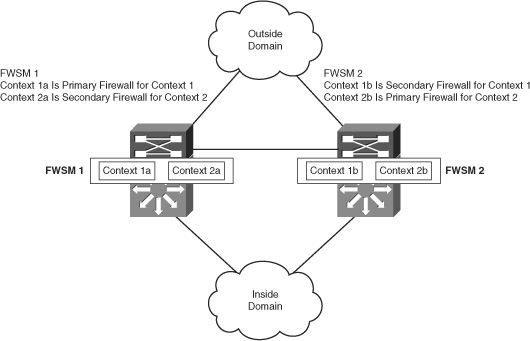
In the network in Figure 12-4, the static route from the switch has a next hop defined as the interface of the primary FWSM for the subnets in the inside security zone. The FWSM has a default route with a next hop to the outside VLAN 9 HSRP VIP address. The FWSM also points to the route for the subnets, which constitutes the inside security domain to the VLAN 10 VIP HSRP address. The inside interface of the FWSM is in VLAN 10.
Table 12-1 lists the first configuration that needs to be enabled for the failover. The configuration enables the primary and secondary FWSMs to communicate. In Figure 12-4, VLAN 30 represents failover link, and VLAN 31 represents the state link. When the FWSM is configured with failover lan unit primary, it becomes a primary FWSM, and when the peer FWSM is configured with failover lan unit secondary, it becomes the secondary FWSM. Before configuring any other interfaces for failover, the commands in Table 12-1 must be enabled on both the FWSMs.
Table 12-1 Active/Standby Failover Configuration

Figure 12-4 Single Context FWSM Failover
Example 12-1 shows the configuration for the primary FWSM in the topology shown in Figure 12-4.
Example 12-1 Primary FWSM configuration
Now focus your attention on the secondary FWSM for the topology shown in Figure 12-4.
The secondary FWSM has only configuration statements based on Table 12-1. After the primary FWSM is configured, the write standby command will enable all configurations to the secondary FWSM.
When you use write standby in the primary FWSM, the output for show run for the secondary FWSM is as shown in Example 12-2.
Example 12-2 Secondary FWSM configuration
The output in Example 12-3 confirms the configuration of failover for both the primary and secondary FWSMs in the topology, shown in Figure 12-4.
Example 12-3 Verifying Failover for the Primary and Secondary FWSM Configurations
The single context FWSM failover is configured in Active/Standby mode. The commands in Table 12-1 are very important to define the functionality of the two FWSMs as primary and secondary.
Configuring Multiple Context FWSM Failover
This section for multiple context mode goes through Active/Active mode of configuring FWSM. The two FWSMs are present in two different chassis. The spanning tree of the VLAN representing the active firewall context should be represented in the same switch. The HSRP VIP for the VLAN should also be represented in the same switch. If the HSRP Spanning Tree Protocol (STP) root follows the placement of primary context, this will reduce the traffic that passes between the two chassis. In this way, the traffic that enters the switch has active context FWSM and leaves through the same switch. The route statements will be similar to the description in single context mode covered in the previous section. The only difference is that the routes will be mentioned based on the context of the firewall.
Figure 12-5 shows an example of Active/Active context using failover groups. Here, both the FWSMs are actively passing traffic for the respective contexts.
Figure 12-5 Network Topology for Multiple Context FWSM Failover
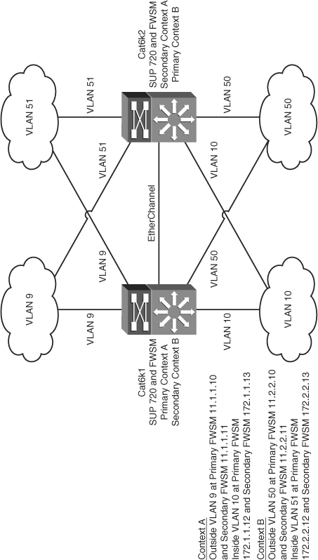
NOTE | The configuration for failover for routed mode or transparent mode is the same except for the way the VLANs are defined in the transparent mode. The failover configuration must allow BPDUs through the FWSM, which can be done using an EtherType access list. |
Example 12-4 shows the multiple context failover configuration for the primary FWSM. Refer to the topology shown in Figure 12-5.
Example 12-4 Primary FWSM System Configuration
FWSM# show run
: Saved
:
FWSM Version 3.1(4) <system>
!
resource acl-partition 12
hostname FWSM
enable password 8Ry2YjIyt7RRXU24 encrypted
!
interface Vlan9
!
interface Vlan10
! VLAN 30 represents a failover link
interface Vlan30
description LAN Failover Interface
! VLAN 31 represents State link
interface Vlan31
description STATE Failover Interface
!
interface Vlan50
!
interface Vlan51
!
passwd 2KFQnbNIdI.2KYOU encrypted
class default
limit-resource IPSec 5
limit-resource Mac-addresses 65535
limit-resource ASDM 5
limit-resource SSH 5
limit-resource Telnet 5
limit-resource All 0!ftp mode passive
pager lines 24
! Configure failover
failover
! configure unit as a primary FWSM
failover lan unit primary
! VLAN 30 is configured as a failover link and VLAN 31 as a state link
failover lan interface fover Vlan30
failover link flink Vlan31
! configure IP addresses for the interfaces for failover and state link.
! These VLANS should be trunked in the switch between the two chassis
failover interface ip fover 192.168.1.1 255.255.255.0 standby 192.168.1.2
failover interface ip flink 192.168.2.1 255.255.255.0 standby 192.168.2.2
! Active/Active mode introduces the concept of failover group. Each failover group ! has properties attached per context or attached to multiples contexts. In this
! case, there are two contexts.
! The failover group 1 is active in the primary unit and the failover group 2
! is active in the secondary unit
failover group 1
preempt
replication http
failover group 2
secondary
preempt
replication http
no asdm history enable
arp timeout 12400
console timeout 0
admin-context admin
context admin
allocate-interface Vlan10
allocate-interface Vlan9
config-url disk:/admin.cfg
!
! contexta is attached to failover group 1
context contexta
allocate-interface Vlan10
allocate-interface Vlan9
config-url disk:/contexta.cfg
join-failover-group 1
!
! contextb is attached to failover group 2
context contextb
allocate-interface Vlan50
allocate-interface Vlan51
config-url disk:/contextb.cfg
join-failover-group 2
!
prompt hostname context
Cryptochecksum:3499722301e9febd9f25ced03d4bec32
: end
It is necessary to configure the secondary FWSM to identify the failover link and state link, as demonstrated in Example 12-5. The secondary FWSM obtains the context configurations from the primary FWSM when failover is enabled. The preempt command in the failover group configurations cause the failover groups to become active on their designated unit after the configurations have been synchronized and the preempt delay has passed. Make sure these VLANs are defined in the switch and allowed in the trunk.
Example 12-5 Configuring the System Context of the Secondary FWSM
failover
failover lan unit secondary
failover lan interface fover Vlan30
failover replication http
failover link flink Vlan31
failover interface ip fover 192.168.1.1 255.255.255.0 standby 192.168.1.2
failover interface ip flink 192.168.2.1 255.255.255.0 standby 192.168.2.2
Example 12-6 gives a snapshot of the commands needed to configure context A in the primary FWSM, from theshow running-config output.
Example 12-6 Active Context A Configuration (Primary FWSM)
Example 12-7 Active Context B Configuration (Secondary FWSM)
interface Vlan9
nameif outside
security-level 0 ip address 11.1.1.12 255.255.255.0 standby 11.1.1.13
!
interface Vlan10
nameif inside
security-level 100
ip address 172.1.1.12 255.255.255.0 standby 172.1.1.13
!
access-list 100 extended permit ip any any
pager lines 24
mtu outside 1500
mtu inside 1500
monitor-interface outside
monitor-interface inside
icmp permit any outside
icmp permit any inside
global (outside) 1 11.1.1.0 netmask 255.255.255.0
nat (inside) 1 0.0.0.0 0.0.0.0
access-group 100 in interface outside
access-group 100 out interface outside
access-group 100 in interface inside
access-group 100 out interface inside
route outside 0.0.0.0 0.0.0.0 11.1.1.3 1
Example 12-7 gives a snapshot of the commands needed to configure context B in the secondary FWSM, from the show running-config command output.
interface Vlan50
nameif inside
security-level 100
ip address 172.2.2.10 255.255.255.0 standby 172.2.2.11 ! interface Vlan51
nameif outside
security-level 0
ip address 11.2.2.10 255.255.255.0 standby 11.2.2.11!
passwd 2KFQnbNIdI.2KYOU encrypted
access-list 100 extended permit ip any any
access-list 101 extended permit ip any any
pager lines 24
mtu inside 1500
mtu outside 1500
monitor-interface inside
monitor-interface outside
icmp permit any inside
icmp permit any outside
no asdm history enable
arp timeout 12400
global (outside) 1 11.2.2.0 netmask 255.255.255.0
nat (inside) 1 0.0.0.0 0.0.0.0
access-group 101 in interface inside
access-group 101 out interface inside
access-group 101 in interface outside
access-group 101 out interface outside
route outside 0.0.0.0 0.0.0.0 11.2.2.3 1
Use the show failover command to verify the failover in each context. The “Configuring Multiple Context FWSM Failover” section shows Active/Active context configuration. The 3.x code supports Active/Active features. The example shows configurations of failover groups and how they are attached to each context. The failover group gives distinct failover characteristics to each context. This helps achieve Active/Active configurations for multiple context mode and use both the FWSM units.
Summary
After reading this chapter, you should know the following key topics:
• The redundancy concept in FWSM—Active/Active and Active/Standby
• Understanding state link and failover link in a FWSM
• Requirements needed to enable redundancy in the FWSM
• Understanding redundancy parameters of a FWSM, such as poll interval and monitoring
• Configuration of Active/Standby and Active/Active modes of failover in FWSM