Chapter 17 Asymmetric Routing
This chapter provides an overview of asymmetric routing prevalent in the enterprise network. You will learn how the placement of a firewall in a network breaks an asymmetric flow. This chapter also includes designs for symmetric routing with firewalls and covers the FWSM feature that supports asymmetric routing.
In asymmetric routing, the packet traverses from a source to a destination in one path and takes a different path when it returns to the source. Asymmetric routing is not a problem by itself, but will cause issues when Network Address Translation (NAT) or firewalls are used. For example, in firewalls, state information is built when the packets flow from a higher security domain to a lower security domain. The firewall will be an exit point from one security domain to the other. If the return path passes through another firewall, the packet will not be allowed to traverse the firewall from the lower to higher security domain because the firewall in the return path will not have any state information. The state information exists in the first firewall.
Asymmetric Routing Without a Firewall
Figure 17-1 shows asymmetric routing without firewalls in the path from a source to a destination. The source is in 10.1.1.0 subnet, with a source IP address 10.1.1.100. The destination for the packet flow is 11.1.1.100. The Flow 1 depicts the flow from source to the destination. The host 11.1.1.100 receives the communication and transmits it back to the source 10.1.1.100 (in 10.1.1.0 subnet). In the return path, R1 routes the packet to R3. Note that the packet should have been forwarded to R2 to take the same path of Flow 1 (in Figure 17-1). From R3 the packet flows to Cat6k2 and then to R4. Even though the path from the source to destination is different from the return path of the packet, the flow is completed without any issue. In a routing environment, the component of latency needs to be reviewed for different paths.
Figure 17-1 Asymmetric Routing Without a Firewall

Asymmetric Traffic Flow in a Firewall Environment
Figure 17-2 FWSM and Asymmetric Routing
In Figure 17-2, there are two FWSMs (for firewalls) added in both the Catalyst 6500 chassis. The asymmetric traffic flow is from 10.1.1.0 subnet to host 11.1.1.100.

The source for the flow is in the inside security domain, and the destination is in the outside security domain. The Flow1 depicts the flow of the packet from source to destination. The FWSM 1 forms a state translation when the packets traverse the firewall. The flow is from a higher security domain (inside) to a lower security domain (outside). The host 11.1.1.100 receives the communication and transmits back to the source 10.1.1.100 (in 10.1.1.0 subnet). In the return path, the R1 routes the packet to R3. Note that the packet should have been forwarded to R2 to pass through FWSM 1. The packet flows from R3 to FWSM 2. FWSM 2 looks for state translation entry for this flow and because no state translation entry exists, the packet is dropped.
This example shows how asymmetric routing can cause problems in a firewall environment when a packet traverses from one security domain to another security domain. The next section covers options to overcome asymmetric routing in a firewall environment.
Avoiding Asymmetric Routing Through Firewalls
The next section covers options for a symmetric traffic flow in a firewall environment with and without redundancy.
Option 1: Symmetric Routing Through Firewalls
Make sure the routing flows through the desired symmetric architecture as shown in Figure 17-3.
Figure 17-3 Symmetric Routing Through Firewalls Without Redundancy
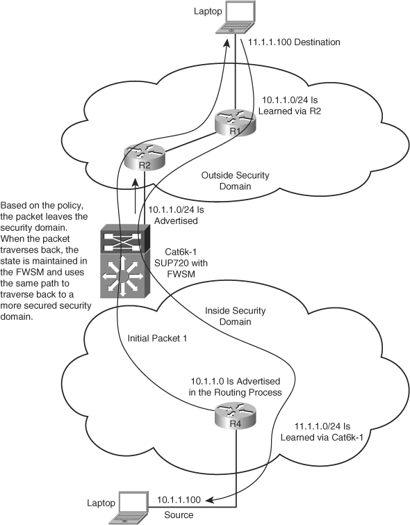
In this example, the packet traverses through the Cat6k-1 and the FWSM. Based on the security policies, the state is maintained in the FWSM. When the packet originates from the source 10.1.1.100, it flows through the FWSM1, builds a state table, and then flows to the destination 11.1.1.100. On the return path, the packet traverses through the same path because the route for subnet 10.1.1.0 at R1 is learned only via R2. The packet reaches the Cat6k-1 and the FWSM.
The state is maintained for the packet flow in the FWSM1 and the packet is allowed to traverse through FWSM1 to reach R4.
The next section covers the redundancy component added to Figure 17-3.
Option 2: Firewall Redundancy and Routing Redundancy Symmetry
Figure 17-4 shows the failover capability of the firewall and the routing decision to follow the failover state of the firewall. This design has redundancy for the FWSM and Layer 3 portion of the network in each security domain. This is achieved by using the Layer 3 devices to point to the virtual IP address (VIP) of the active interface for a particular security domain. The FWSM points to the VIP address of the Hot Standby Router Protocol (HSRP) for the respective VLANs. In this case, the FWSM can also take advantage of the redundant Layer 3 devices in the network. The FWSM is configured in routed mode. Layer 3 redundancy will prevent multiple failures in the Layer 3 domain. For more information on achieving this type of redundancy, refer to Chapter 12, “Understanding Failover in FWSM.”
Figure 17-4 FWSM Redundancy and Routing Symmetry to Avoid Asymmetric Routing

Supporting Asymmetric Routing in FWSM
The FWSM supports asymmetric traffic flow from the 3.x code version and later. The previous section covers the problems caused by routing while introducing firewalls in asymmetric routing and gives a solution with and without redundancy to avoid these problems in the network. The solution aligns the firewalls with the Layer 3 network to avoid asymmetric routing issues. Asymmetric routing problems can occur when traffic flows between multiple security domains and these security domains are represented in a multiple context firewall. In this case, the flow of traffic for all security domains will be achieved by using symmetric firewall redundancy, congruent with the routing architecture. FWSM redundancy can be designed using Active/Standby and Active/Active modes.
The concept of asymmetric routing can be applied to single or multiple context mode. Asymmetric routing (ASR) feature support is available in 3.1 code version and later to support asymmetric routing. Based on the 3.1 code, the FWSM can have a maximum of 32 groups of ASR. The ASR support is also available in transparent and routed firewalls.
In this section, you will learn to support asymmetric routing using the following failover modes:
Active/Standby mode
Active/Active mode
Asymmetric Routing Support in Active/Standby Mode
For the network topology shown in Figure 17-5, the configuration for the outside interface of security context A and security context B will have ASR group 1 (it will belong in the same ASR group) enabled. The packet arrives at the outside interface of context B. Because the ASR group is the same for the two outside interfaces of contexts A and B, the packet will get redirected to context A’s outside interface from context B’s outside interface. The packet then flows through context A to reach the destination.
Active/Active FWSM configuration is leveraged in an environment that has routing redundancy. This design increases the redundancy and availability of resources for the traffic flow.
Figure 17-5 FWSM and Asymmetric Routing Support Between Two Contexts

Asymmetric Routing Support in Active/Active Mode
In Active/Active mode, the two FWSM units in failover state are active. This is achieved using multiple context mode. The active firewalls for the respective contexts are distributed between the two FWSM units in failover mode.
Consider a scenario where a packet flows through a single security rule set. When a need exists to have two desired paths, a redundant path can be designed using Active/Active redundancy and the ASR feature in the FWSM. The same rule set is applied in both contexts. ASR group is enabled in the interfaces of the two contexts. The firewall is configured to be in transparent mode.
For the network topology shown in Figure 17-6, the FWSMs are in Active/Active failover configuration.
Figure 17-6 FWSM and Asymmetric Routing Support Between Two Contexts in Active/Active Failover Mode

The firewalls in both contexts are in transparent mode, and the security policies in both the contexts are the same. From the Layer 3 next hop in each security domain, there are two equal paths for routing adjacencies across the firewall through the two contexts. The traffic from the inside to outside security domain can flow through either context A or context B because the ASR feature is enabled on the interfaces of each security domain of both contexts. The dependence on state information is removed because of the ASR feature.
In this example, the packet from the inside to the outside security domain flows through Cat6k-1 context A. In the return path, the packet flows to context B in the Cat6k-2. The outside interfaces of the two contexts are in the same ASR group. After the packet arrives in context B, the outside interface of context B finds the session information in the outside interface of context A (because they are configured with the same ASR group), which is in the standby state on the unit. It then forwards the return traffic to the unit where context A is active.
Asymmetric routing concepts can also be extended to the single context mode. In this case, the packet leaves the FWSM interface in a security domain, and the return path will be in an interface of a different security domain. Note that both the interfaces will be in the same ASR group. The interfaces in the same ASR group will pass the packet from one interface to the other. However, in multiple context mode, the interfaces in the same security domain share the same ASR group.
In general, avoid asymmetric routing in a firewall design solution. The ASR feature is purely to protect issues such as link failovers. Note that even though state is shared between the Active and Standby firewalls periodically, it is possible to have race conditions, which could cause connections to be dropped.
Active/Active failover with ASR is a design advantage for parallel paths across firewalls with the same security rule sets. Care should be taken for Active/Active redundancy and the Layer 3 network symmetry. This depends on each environment, and limitations may arise based on individual scenarios.
Configuring ASR in FWSM
The command to enable the ASR feature introduced in the 3.1 code release for the FWSM is
asr-group number
This command-line interface (CLI) should be attached to the interface configuration, for example:
interface vlan 9
nameif outside
security-level 0
ip address 11.1.1.10 255.255.255.0 standby 11.1.1.11
asr-group 1
Example 17-1 represents the FWSM in multiple context routed mode. ASR groups are configured to allow the FWSM to pass the traffic.
The spanning tree root for a VLAN is represented by the switch with an active firewall context, and HSRP Primary for the VLAN is represented in the same switch.
Figure 17-7 gives an example of Active/Active context using failover groups. The outside interfaces of both context A and context B are configured for ASR routing with asr-group 1.
Figure 17-7 FWSM and Asymmetric Routing Support in Multiple Context Routed Mode

Next is the snapshot configuration of FWSMs in multiple context mode with ASR group.
Example 17-1 FWSM and Asymmetric Routing Support in Multiple Context Routed Mode
! (Cat 6k1) FWSM primary for contexta
FWSM/contexta# show run
: Saved
:
FWSM Version 3.1(4) <context>
!
hostname contexta
enable password 8Ry2YjIyt7RRXU24 encrypted
names
!
interface Vlan9
nameif outside
security-level 0
ip address 11.1.1.12 255.255.255.0 standby 11.1.1.13
asr-group 1
! ASR group 1 is configured for the interface in the outside security domain
interface Vlan10
nameif inside
security-level 100
ip address 172.1.1.12 255.255.255.0 standby 172.1.1.13
!
passwd 2KFQnbNIdI.2KYOU encrypted
access-list 100 extended permit ip any any
pager lines 24
mtu outside 1500
mtu inside 1500
monitor-interface outside
monitor-interface inside
icmp permit any outside
icmp permit any inside
no asdm history enable
arp timeout 14400
global (outside) 1 11.1.1.0 netmask 255.255.255.0
nat (inside) 1 0.0.0.0 0.0.0.0
access-group 100 in interface outside
access-group 100 out interface outside
access-group 100 in interface inside
access-group 100 out interface inside
route outside 0.0.0.0 0.0.0.0 11.1.1.3 1
timeout xlate 3:00:00
timeout conn 1:00:00 half-closed 0:10:00 udp 0:02:00 icmp 0:00:02
timeout sunrpc 0:10:00 h323 0:05:00 h225 1:00:00 mgcp 0:05:00
timeout mgcp-pat 0:05:00 sip 0:30:00 sip_media 0:02:00
timeout uauth 0:05:00 absolute
no snmp-server location
no snmp-server contact
telnet timeout 5
ssh timeout 5
!
class-map inspection_default
match default-inspection-traffic
!
policy-map global_policy
class inspection_default
inspect dns maximum-length 512
inspect ftp
inspect h323 h225
inspect h323 ras
inspect netbios
inspect rsh
inspect skinny
inspect smtp
inspect sqlnet
inspect sunrpc
inspect tftp
inspect sip
inspect xdmcp
!
service-policy global_policy global
Cryptochecksum:2873ca18580fb555ea47c15d0ac94a08
: end
FWSM/contexta#
! (Cat 6k2) FWSM primary for contextb
FWSM/contextb# show run
: Saved
:
FWSM Version 3.1(4) <context>
!
hostname contextb
enable password 8Ry2YjIyt7RRXU24 encrypted
names
!
interface Vlan50
nameif inside
security-level 100
ip address 172.2.2.10 255.255.255.0 standby 172.2.2.11
!
interface Vlan51
nameif outside
security-level 0
ip address 11.2.2.10 255.255.255.0 standby 11.2.2.11
asr-group 1
! ASR group 1 is configured for the interface in the outside security domain
passwd 2KFQnbNIdI.2KYOU encrypted
access-list 100 extended permit ip any any
access-list 101 extended permit ip any any
pager lines 24
mtu inside 1500
mtu outside 1500
monitor-interface inside
monitor-interface outside
icmp permit any inside
icmp permit any outside
no asdm history enable
arp timeout 14400
global (outside) 1 11.2.2.0 netmask 255.255.255.0
nat (inside) 1 0.0.0.0 0.0.0.0
access-group 101 in interface inside
access-group 101 out interface inside
access-group 101 in interface outside
access-group 101 out interface outside
route outside 0.0.0.0 0.0.0.0 11.2.2.3 1
timeout xlate 3:00:00
timeout conn 1:00:00 half-closed 0:10:00 udp 0:02:00 icmp 0:00:02
timeout sunrpc 0:10:00 h323 0:05:00 h225 1:00:00 mgcp 0:05:00
timeout mgcp-pat 0:05:00 sip 0:30:00 sip_media 0:02:00
timeout uauth 0:05:00 absolute
no snmp-server location
no snmp-server contact
telnet timeout 5
ssh timeout 5
!
class-map inspection_default
match default-inspection-traffic
!
policy-map global_policy
class inspection_default
inspect dns maximum-length 512
inspect ftp
inspect h323 h225
inspect h323 ras
inspect netbios
inspect rsh
inspect skinny
inspect smtp
inspect sqlnet
inspect sunrpc
inspect tftp
inspect sip
inspect xdmcp
!
service-policy global_policy global
Cryptochecksum:b59531047507cf7e9ee7effb2cce9a21
: end
Summary
Asymmetric routing is the traversal of a packet from a source to a destination in one path, and follows a different path when the packet returns to the source. Asymmetric routing is seen in the Layer 3 environment and does not cause a problem by itself. Asymmetric routing with firewalls causes issues. After reading this chapter, the reader will know to overcome asymmetric routing issues in a network with FWSM. It is a good practice to follow the design options for symmetric routing. The reader will also know to enable the ASR feature to support asymmetric routing for the FWSM with the 3.1 code version or later.