Chapter 7 Configuring the FWSM
This chapter takes you through the steps needed to configure the Firewall Services Module (FWSM). This chapter also covers the different FWSM mode configurations: routed, transparent, single context, and multiple contexts.
The FWSM is an inline module in the switch chassis. To configure the FWSM, switch configuration is a necessity because it relates the switch to the FWSM. The configuration of FWSM covers the details of firewall rules, policy, redundancy, and so on.
The configuration of the FWSM is a two-fold process:
Step 1 | Configure the FWSM in the switch. |
Step 2 | Configure the FWSM for security rules. |
The sections that follow describe this two-fold process in greater detail.
Configuring FWSM in the Switch
The configuration of the switch for the FWSM is important because it builds the VLANs that are added between the switch and FWSM. These VLANs will be trunked between the switch and FWSM.
Follow these steps in the first configuration:
The highlighted portion in the output shows that the FWSM is in the module 4.
Step 2 | Assign VLANs to the FWSM: The FWSM does not use external interfaces. The interfaces used in the FWSM are Virtual Local Area Networks (VLAN). These VLANs create a relationship between the switch and the FWSM. |
For more details about EtherChannel connections to FWSM refer to Chapter 6, “Configuring and Securing the 6500/7600 Chassis.” This gives a description of the EtherChannel connection between the FWSM and the switch. | |
The firewall VLANS are defined through the vlan-group command on the switch. This command enables the VLANs on the firewall. | |
Guidelines for assigning VLANs on FWSM are as follows: | |
— Assign the VLAN for the FWSM before it is applied to the Multilayer Switch Feature Card (MSFC). | |
— Reserved VLANs cannot be used. | |
— VLAN 1 cannot be used. | |
— If FWSM failover is used within the same switch chassis, do not assign the VLAN(s) reserved for failover and stateful | |
— As soon as the configuration for VLANs is enabled in the vlan-group command on the switch, the VLAN information from the supervisor database is sent to the FWSM. | |
The following list of commands needs to be enabled on the Policy Feature Card (PFC) for adding the VLANs to the FWSM: | |
(a)Configure the VLAN group with respect to the module slot for the FWSM: | |
firewall module module_number vlan-group firewall_group | |
(b)Configure the VLANs that will represent the security zones in the FWSM: | |
firewall vlan-group firewall_group VlANs |
NOTE | To determine the module number, type the show module command. |
For example:
firewall module 4 vlan-group 1
firewall vlan-group 1 50,51,100,101,325
For security reasons, only one Switch Virtual Interface (SVI) can exist between the FWSM and the switch by default. This means that for all the VLANs defined in the FWSM, only one VLAN can have an SVI interface in the switch.
The designs in the data center with Multiprotocol Label Switching (MPLS)/Layer 3 VPN technology will need to have two SVIs. This is covered in Chapter 23, “Design Scenarios.”
For this case, it is desirable to have more than one SVI interface in the MSFC, for the VLANs defined in the FWSM. The command to enable this feature is
firewall multiple-vlan-interfaces
The command syntax for switch configuration to enable VLANs in the FWSM follows:
firewall multiple-vlan-interfaces
firewall module 4 vlan-group 1
firewall vlan-group 1 50,51,100,101,325
This section covers configuring the switch for FWSMs functionality. The configuration provides the VLANs that can be used in the FWSM. In this section, it is important to understand how the traffic enters and exits the FWSM. The VLANs must be carefully configured; otherwise, the traffic can bypass the FWSM.
Exploring Routed Mode
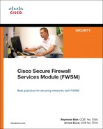
In routed mode, the FWSM acts like a Layer 3 device, and all the interfaces in the FWSM need to have an Internet Protocol (IP) address. The interfaces can be in any security zone: inside, outside, or demilitarized zone (DMZ). The firewall configuration is in routed mode and needs IP addresses and IP routing enabled on the interfaces. The routed mode can be in single context or multiple context mode. Figure 7-1 illustrates the high-level details of each mode.
Figure 7-1 High-Level Topology View of FWSM in Routed Mode

This section covers the details of different modes supported in the FWSM. It is very important to understand the basics of each mode.
In a routed mode, FWSM will not allow non-IP traffic to pass through the firewall. The routed mode can be represented in two modes: single and multiple contexts.
• Single Context Mode: A single context mode will have single security policy. The features unique to a single context mode, which cannot apply to the multiple context mode, are the following:
— FWSM can participate in multicast domain.
— Routing protocol support is available in single context mode.
• Multiple Context Mode: A single FWSM can be partitioned into multiple security contexts. Each of the security contexts will have separate firewall security policies. By this, a single FWSM is virtualized to facilitate multiple security policies. Some of the points to be noted for multiple context mode are the following:
— The FWSM cannot take part in multicast domain.
— Routing protocol support for the FWSM is not available in multiple context mode.
— Active/Active redundancy can be enabled with Asymmetric routing. This cannot be done in the single context mode. These features are supported in the 3.x release.
Routed mode can support both single and multiple context modes. The configuration of single or multiple context modes depends on the design requirements. It is very important to understand the limitation of single and multiple context modes to make the correct design decision.
Exploring Transparent Mode
The firewall is not seen as a Layer 3 hop. The FWSM has a Layer 2 adjacency with the next hop devices. The firewall can be referred to as a bump in the wire.
The transparent firewall also facilitates the flow of IP and non-IP traffic. To place the firewall between two Layer 3 devices, no IP readdressing is required. It is also easy to establish routing protocol adjacencies through a transparent firewall. Likewise, protocols such as Hot Standby Routing Protocol (HSRP) or Virtual Router Redundancy Protocol (VRRP) can run through the security device. Non-IP traffic such as IPX, bridge protocol data units (BPDU), or even MPLS can be configured to pass through the firewall, with a simple Ether-type–based access list. Network Address Translation (NAT) can be enabled in 3.1 and later codes. Transparent mode can also be represented in a single or multiple context mode.
Figure 7-2 represents transparent mode in a single context and multiple context environment.
Figure 7-2 High-Level Topology View of Firewall in Transparent Mode
This type of firewall can fit in any design. It easily becomes a part of the network because no considerations are needed for routing or changing the default route address for the servers, when Layer 2 transparent firewalls are introduced in the network.
Using Multiple Context Mode for FWSM
In the multiple context mode for FWSM, the firewall is virtualized into multiple security domains. This facilitates virtualization of the security domains with firewalls.
Prior to multiple context mode, multiple security rules were written in a single firewall rule set, which made the firewall rule set configuration more complex. With multiple context mode, a more granular approach to the rule set can be achieved, where each individual rule set is treated as a separate entity. The changes made in one context will not affect the other policies. Multiple context mode helps in integration of security virtualization with network virtualization.
Each context has its own security policy, interfaces, and administrators. Multiple context mode is similar to having multiple standalone firewall devices, where each firewall represents a security policy and has separate incoming and outgoing interfaces.
The following features will not be available in multiple context firewalls compared to single context firewalls:
• Support for dynamic routing protocols (BGP stub mode or static routes in multiple context mode is supported)
• Multicast routing support (multicast bridge support is available in transparent mode)
In a multiple context mode, the administrator has configurations of a standalone firewall, such as security policy, interfaces, and almost all the options you can configure on a standalone device. You can store context configurations on the internal flash memory or the external flash memory card, or you can download them from a Trivial File Transfer Protocol (TFTP), File Transfer Protocol (FTP), Hypertext Transfer Protocol (HTTP), or Hypertext Transfer Protocol over Secure Socket Layer (HTTPS).
In a multiple context mode, it is very important to understand the types of contexts available and their uses. The next section explains the different context configurations.
Context Configurations
A context has the configuration of the security policy for a specific security domain in the firewall. Administrators can configure all options as a standalone device. A context will have interfaces (VLANs), and each interface is in a security zone based on the rule set. A context is like a physical firewall with separate interfaces and separate security policy in a virtual environment. In the FWSM, in multiple context mode, you can have multiple contexts with different firewall characteristics.
System Context Configurations
The system context adds and manages the context configuration. The system context does not have any interface allocation; it defines the VLANs for the respective contexts. The definition of other contexts is given in system context. Failover command configuration is enabled in the system configuration.
Admin Context Configurations
In the admin context, the user can log in and access the system and other contexts. The user can be granted privileges over all the contexts, and the administrator can restrict a few of these privileges based on the user access criteria. The admin context must reside on flash memory, not remotely. Admin context is created automatically, resides in the flash memory, and is called admin.cfg.
Packet Classifier in FWSM Context Mode
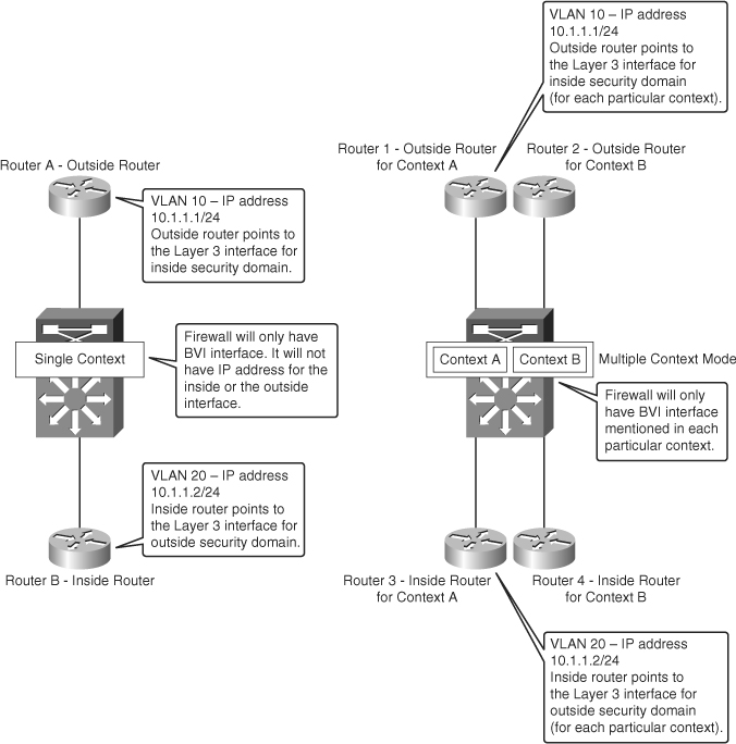
One of the modes in which FWSM can be deployed is the shared outside interface mode. The outside interface is shared between multiple contexts. This translates to one interface for all the contexts in the outside security zone. The packet destined to the outside interface must traverse to a specific context, which has the state information built into it. The traffic is not allowed to traverse the FWSM context if no state information exists. This is for the packets flowing from the lower security zone to the higher security zone. Therefore, in a common shared interface, it is important for the packet to flow to the correct context. The packet classifier takes care of this flow from a shared interface to the respective context that has the state information for the flow. Figure 7-3 illustrates the firewall with a shared outside interface for multiple context mode.
Figure 7-3 Packet Classifier in FWSM Context Mode
In the example shown in Figure 7-3, VLAN 10 is the outside interface for context A and context B. When the packet in the return path from the outside security zone enters context B, the packet passes through VLAN 10. The state table is built during the initial packet flow from the inside to the outside security zone. At the FWSM, the packet passes through a packet classifier. The packet classifier forwards the packet to the context B and then to VLAN 11.
The purpose of the classifier is to determine the context to which the packet needs to be sent when the packet arrives on a shared interface. The source-destination-flow identification in a VLAN cannot be based on a MAC address. For example, a packet flowing from the outside to the inside interface of context B arrives first at VLAN 10 and will have the MAC address of VLAN 10. VLAN 10 is shared between the two contexts (sharing the common outside interface) in this example. The classifier intercepts the packet and performs a destination IP address lookup. The main field that is looked up is the destination IP field. The classifier has knowledge of the subnets located behind the security context through xlate and static translations. The classifier does not have knowledge of the routing statements of each context. Using the static and xlate table in the context, the packet comparison for the destination is done and is forwarded to the correct context. In this way, packets can flow from one context to the other, even if there is one shared outside interface representing each of the contexts.
Understanding Resource Management in Contexts
If no resource management is done in a multiple context mode, the context resides in the default class and can access unlimited resources. The following sessions are allowed in the default class per context:
• Telnet sessions: 5 sessions
• SSH sessions: 5 sessions
• IPsec sessions: 5 sessions
• MAC addresses: 65,535 entries
When resource management is enabled, resource restriction is done from the default resource available. Chapter 5, “Understanding Contexts,” provides more details for resource management and memory partition.
Configuration Steps for Firewall Services Module
This section discusses three main configuration examples:
• Type 1: Single Context Routed Mode
• Type 2: Single Context Transparent Mode
• Type 3: Multiple Context Mixed Mode
Type 1: Configuring Single Context Routed Mode
This section covers the configuration of a single context routed mode. There are three main steps for configuring a single context routed mode in the FWSM. These are sequential steps that must be followed in the same order.
Step 1 | Configuring the PFC. This step covers the configuration of the switch in relation to the FWSM configuration. |
The following command is used to enable multiple SVIs in relation to FWSM: | |
firewall multiple-vlan-interfaces | |
This command is needed only if VLAN 9 and VLAN 10 have SVI interfaces in the PFC. If two SVIs are needed for security segregation, the administrator can configure the SVI in two separate VRFs (Virtual Routing and Forwarding). | |
The following command is used to configure the VLAN group used in the FWSM: | |
firewall module 3 vlan-group 1 | |
The module information is based on the output of the show module command. | |
The following command is used to configure the VLANs in the VLAN group: | |
firewall vlan-group 1 9,10 | |
VLANs used in the FWSM and the failover VLANs should be configured in this command. In multiple context mode, all the VLANs in different contexts should also be configured to the VLAN group defined in the firewall module 3 vlan-group 1 command. | |
When the SVI of the inside and outside interfaces are defined on the same PFC, a form of segregation is required to prevent the traffic from bypassing the FWSM. In the traditional model, it is recommended to define either the inside or the outside VLANs SVI in the PFC. The VLAN that does not have SVI defined in the PFC will have the Layer 3 interface enabled in the Layer 3 next hop device. |
NOTE | The SVI configuration or the Layer 3 interface configuration for the respective inside and outside interface is not shown in this section. |
Type 2: Configuring Single Context Transparent Mode
In the transparent mode, the FWSM is a bump on the wire. The next-hop devices will have only a Layer 2 relationship with the FWSM. This section shows the steps for the configuration of the transparent mode in a single context mode.
Step 1 | Configure the Policy Feature Card (PFC). |
Step 1 covers the switch configuration in relation to the FWSM: | |
firewall multiple-vlan-interfaces | |
The details are similar to the explanation provided in Step 1 of the Type 1 example. In transparent mode, there can be only two interfaces for a context. |
Step 2 | Access the FWSM from the switch and configure the mode on the FWSM: |
6504-E-2# sess slot 4 pr 1 | |
The slot number of the FWSM is identified from the show module command output in the PFC. |
Step 3 | Verify the mode and functionality of the FWSM from the output shown next: |
FWSM# sh mod | |
The FWSM is in single context transparent mode. |
NOTE | While configuring the transparent mode in FWSM, it is important to specify the MAC address and the CAM entries on the Layer 3 next hop device of FWSM. |
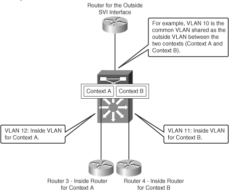
Type 3: Configuring Multiple Context Mixed Mode
The multiple context configuration shown in this section is with mixed mode; one of the contexts is in transparent mode, and the other is in routed mode. The configuration for multiple context mode is divided into four steps. Figure 7-4 shows the mixed mode configuration of Figure 7-4.
Figure 7-4 Mixed Mode Configuration of FWSM
Step 1 | Configure the PFC. |
This step covers the configuration of the switch in relation to the FWSM configuration: | |
firewall multiple-vlan-interfaces | |
The explanation is similar to the explanation for the Step 1 configuration in Type 1 example. |
Step 3 | Configure the FWSM. |
This step shows the configuration of the system context; VLANs in the FWSM are configured and context allocation is done. | |
— Configure the system configuration: | |
interface vlan 20 |
NOTE | Make a note of the system configuration. The failover configuration should be enabled in this context. This section does not cover failover configuration. For information about failover configuration, see Chapter 12, “Understanding Failover in FWSM.” |
NOTE | If DMZ exists, the interface has to be defined. For failover, the standby IP address must be configured for the interface IP addresses. |
— Define route information:
route outside 0.0.0.0 0.0.0.0 10.1.1.1 1
NOTE | Static route is configured here. Routes can be specified based on the interface name defined in the context. For example, you can have route statements for the inside routes: route inside 191.1.1.1 255.255.255.255 10.1.2.2. |
—Define translations:
nat (inside) 1 10.1.2.0 255.255.255.0
global (outside) 1 10.1.100.0-10.1.100.29
! This context uses dynamic NAT for inside users that
! access the outside security domain
static (inside, outside) 10.1.100.30 10.1.2.75 netmask 255.255.255.255
! Outside user to access the internal server
access-list INTERNET extended permit ip any any
access-group INTERNET in interface inside
access-list SECRULES extended permit ip any any
access-group SECRULES in interface outside
Transparent configuration example for context B:
To access the context for customer B from the system configuration, the command to be used is
FWSMB# changeto context customerB
— Configure transparent mode.
firewall transparent
— Configure the interfaces.
interface Vlan30
nameif outside
bridge-group 1
security-level 0
!
interface Vlan31
nameif inside
bridge-group 1
security-level 100
!
The Layer 3 interface defined in the Layer 3 router will be in a different VLAN but the same IP subnet.
interface BVI1
ip address 10.100.1.254 255.255.255.0
— Define the access list.
access-group 101 in interface outside
access-group 100 in interface outside
access-group 100 out interface outside
access-group 101 in interface inside
access-group 100 in interface inside
access-group 100 out interface inside
access-list 100 extended permit ip any any
access-list 100 extended permit udp any any
access-list 101 ethertype permit bpdu
This generic access list permits all the traffic.
— Configure the MTU and no failover.
mtu outside 1500
mtu inside 1500
no failover
— Define the respective routes for FWSM management traffic.
route outside 0.0.0.0 0.0.0.0 10.100.1.1 1
Summary
After reading this chapter, you should be able to configure the FWSM. The key topics of FWSM configuration covered in this chapter are the following:
• Switch level configuration for FWSM
• Configuration of single context routed mode
• Configuration of single context transparent mode
• Configuration of multiple context mixed mode