Chapter 16 Multicast
This chapter covers FWSM support for multicast technology. It discusses only the basics of multicast and emphasizes the support of multicast in FWSM. The following are some of the discussion points covered in detail:
• Designs in FWSM to make multicast pass through the firewall
• Features of multicast supported in FWSM
• Configuration examples
NOTE | Before moving on, you should have a good understanding of multicast technology. For more specific details, you can refer to the book, Developing IP Multicast Networks (ISBN 157870079). |
What is multicast? Multicast defines a communication between a single source and multiple receivers through a single stream. In unicast flow, a separate flow is maintained from a source to a destination. For ten receivers to receive a flow from a single source, the network will have ten flows. In multicast stream, this can be achieved in a single flow. For example, one multicast stream from the source can be received by “n” number of receivers in the local-area network (LAN). In multicast stream, the flow will replicate only when there are multiple egress interfaces for the receiver. The local Layer 3 device having multiple egress interfaces to the receivers does the replication of the flow. In multicast, a conservation of bandwidth exists for one-to-many types of communication. The sections that follow offer snapshot concepts of multicast technology.
Protocol Independent Multicast
The multicast tree allows the multicast communication to be established between the source and the receiver. The multicast tree is built using protocol independent multicast (PIM). The communication to build the tree is not dependent on any protocol. It uses the routing protocol in the network to build the tree. Through this multicast tree, one-to-many or many-to-many communication is established.
The following are the four modes of PIM:
• PIM Dense mode: The multicast source sends the traffic to the receiver through the flooding of traffic in a multicast domain. The traffic is pruned at areas of network where there are no receivers. PIM Dense mode is not a scalable solution. There is no concept of rendezvous point (RP) in PIM Dense mode. PIM Dense mode standards are defined in RFC 3973.
The receivers for a particular multicast group will send an Internet Group Management Protocol (IGMP) request to receive the traffic from a particular group. The IGMP request is Layer 2 based. The first hop Layer 3 router maintains the state for all the receivers in the LAN segment and communicates this state using PIM to other Layer 3 devices that have multicast and PIM enabled. During transmission, the source sends the packet to the first hop Layer 3 device, which in turn forwards the packet to the receivers through flooding. This state in every router for multicast forwarding is called a source tree. Source tree is referred to as (S,G) state. The “S” is the IPv4 address of the source and “G” is the multicast group.
• PIM Sparse mode: The communication from the multicast source to the receiver takes place through an explicit multicast tree called the shared tree. The shared tree is centered at an RP. The group entry in the shared tree is created per multicast source. PIM sparse mode standards are defined in RFC 4601.
When the source sends an IGMP join message to the first hop Layer 3 device, the first hop Layer 3 device sends a unicast registry packet to the RP. The first hop Layer 3 device has unicast reachability to the RP through a PIM-enabled interface. The RP then sends a unicast registry stop message back to the Layer 3 first hop device (in case the state exists for the receivers for a particular group at the RP). The multicast traffic flows to the RP. The RP has the state for the receivers that need to join the multicast group and forwards the traffic to the receivers for the particular group. This flow of multicast traffic is through the shared tree. Shared tree is referred to as a (*,G) state. The “*” is any unicast source and “G” is the multicast group.
After the initial traffic flow is established between the source and the destination (the first hop Layer 3 device for the receivers), the destination Layer 3 device calculates the reverse path forwarding (RPF) to the source. If the RPF path to the source is learned better from another PIM-enabled interface other than the RPF interface for the RP, a new path is calculated to the source. The destination Layer 3 device sends the RP prune bit to the RP, and the shared tree (*,G) gets RP pruned. The traffic then starts flowing from the source tree (S,G).
• PIM Bidirectional: PIM builds an explicit bidirectional shared tree. The source tree is not built. By relying on one tree, it reduces the latency component of building two multicast trees, and the memory is conserved.
• Source Specific Multicast (SSM): In SSM, the multicast data forwarding is based on the Source IP address and the Group address. The Source and Group (S,G) multicast flow can be uniquely understood as a channel. SSM always builds a source tree between the receivers and the source. Because the source is known, an explicit (S,G) join message is issued for the source tree. This removes the need for shared trees and RPs in SSM. SSM needs IGMP version 3 enabled in the network.
Understanding Rendezvous Point
The RP is a central point that sees the communication between the source and the receiver. The receivers send IGMP Join messages to the first hop Layer 3 device, called the designated router. The designated router will send the packet to the RP. The RP should be configured on the Layer 3 device and also be reachable from the Layer 3 device through a PIM enabled interface. The RP will maintain the state for the respective groups.
Refer to PIM Sparse mode to understand the functionality of the RP in a multicast tree. This RP information in a network should be advertised to the other Layer 3 routers, referred to as downstream routers. The RP information can be advertised to the entire downstream Layer 3 devices through different methodologies:
• Static RP: All the downstream routers will have RP configuration enabled in the router.
• Auto-RP: The RP information is not configured in the downstream routers. This information is sent from the central RP distribution agent. The groups that function in Auto-RP (in PIM Dense mode) are 224.0.1.39 and 224.0.1.40. These two groups are needed for the propagation of RP information. Auto-RP supports Active/Standby RP redundancy. This is Cisco propriety.
• BSR: The Bootstrap Router (BSR) mechanism is available in PIM version 2. The RP information is not configured in the downstream routers. Devices are configured as candidate BSRs by enabling the ip pim bsr-candidate command. These devices announce themselves to other routers using the 224.0.0.13 group address. Because a message sent to this address is forwarded hop-by-hop throughout the network, all the routers learn about the candidate BSRs and select one of them as an RP. The RP is selected based on the highest priority in the BSR configuration. BSR supports Active/Standby RP redundancy.
• Anycast RP: Anycast RP is an implementation strategy that provides load sharing and redundancy in PIM Sparse mode networks. Multicast Source Discovery Protocol (MSDP) is the key protocol, which makes the Anycast RP redundancy possible. Using Anycast RP, Active/Active RP redundancy is achieved. In Active/Active RP redundancy, both the RPs can function as redundant RPs for sources and receivers at the same time.
PIM Interface Modes
The PIM interface mode defines the functionality of the interface in PIM protocol. There are three interface configuration modes for PIM:
• PIM Dense mode: Interface functions in PIM Dense mode specification. Refer to the PIM Dense mode section in this chapter for functionality details.
• PIM Sparse mode: Interface functions in PIM Sparse mode specification. You will need to configure the RP for multicast delivery. Refer to the PIM Sparse mode section in this chapter for functionality details.
• PIM Sparse-Dense mode: PIM Sparse-Dense mode is essential for the Auto-RP to function. The 12.2.x Mainline and later IOS codes introduce the Auto-RPListener command. Enabling this command in all downstream routers makes auto-rp function in PIM Sparse mode.
IGMP Protocol
IGMP messages are used to allow hosts to communicate to the first hop Layer 3 router on a Layer 2 network, to receive multicast traffic.
There are three types of IGMP versions: IGMPv1, IGMPv2, and IGMPv3.
• IGMP Version 1: The two messages for IGMP version 1 (IGMPv1) are membership Queries and Reports. Queries are sent by the router to All-Hosts 224.0.0.1 address. This is done to solicit a multicast group address for active members. Reports are sent by hosts wanting to receive traffic for a specific multicast group. Membership reports are sent with time-to-live (TTL) 1. The TTL 1 confines the message to the first hop Layer 3 device.
• IGMP Version 2: The two new messages added to IGMP version 2 (IGMPv2) are Group Specific query and Leave Group message. A Group Specific query allows the router to query only membership in a single group, instead of all groups. This is to find out if any member has left the group. This is an optimized solution compared to version 1. You need to know the difference between the Query used in version 1 and the Group Specific query used in version 2. The Query (version 1) uses the multicast to send queries to All-Hosts (224.0.0.1) address, whereas a Group Specific query(version 2) sends the queries to a specific Group “G”. The Leave Group message allows end systems to tell the router that they are leaving the group, which reduces the leave latency for the group on the segment when the member leaving is the last member of the group.
• IGMP Version 3: IGMP version 3 (IGMPv3) adds Group records, each containing a list of multicast sources to INCLUDE or EXCLUDE. In INCLUDE mode, the receiver announces membership to a host group and provides a list of IP addresses from which it wants to receive traffic. This list of IP addresses constitutes an INCLUDE List. In EXCLUDE mode, the receiver announces membership to a host group and provides a list of IP addresses from which it does not want to receive traffic. This constitutes the EXCLUDE List. This provides granular control to avoid rogue sources in the network. This IGMP group is needed for the functionality of SSM mode. Refer to the SSM section in this chapter for more details.
Of the three modes of IGMP versions, the most common version used is IGMP version 2.
Multicast Stub Configuration
Multicast stub configuration does not participate in the PIM neighbor relationship; the device just passes the IGMP messages. In a Layer 3 network world, this type of stub configuration is common in routers connecting to satellite links. In this case, the IGMP messages pass through the satellite unidirectional link using an IGMP helper address configuration or an IGMP unidirectional link configuration in the IOS.
The FWSM can also be configured in stub mode. In stub configuration, the FWSM will not participate in the PIM neighbor relationship. The FWSM acts as an IGMP proxy agent and forwards the host Join and Leave messages from the stub area interface to an upstream interface.
Multicast Traffic Across Firewalls
As more applications adapt to make the optimized use of bandwidth, dependence of these applications on multicast is becoming more prevalent. Therefore, there is an increasing requirement for multicast to traverse from one security domain to the other security domain. The placement of firewalls at the Internet’s edge might require multicast to traverse across the firewall, based on the security environment. In an enterprise data center, the placement of a firewall for security domain segregation has made it very critical for multicast to traverse across the firewalls. With the increased dependency on multicast for application delivery, support for multicast on the firewall is increasingly critical in the data center. The FWSM placed in the data center therefore must support multicast traffic. The support depends on the code version the FWSM is running. The older versions do not support multicast natively.
FWSM 1.x and 2.x Code Releases
FWSM 1.x and 2.x code releases do not support multicast natively. Multicast support in a transparent firewall is facilitated using Access Control Lists (ACL). FWSM support for multicast traffic in 1.x and 2.x code releases can be designed using the following options:
• FWSM in routed mode does not support native multicast. The generic routing encapsulation (GRE) solution is used to encapsulate multicast traffic through FWSMs. In this solution, the multicast traffic is not inspected by the FWSM because it is encapsulated with GRE.
• In transparent mode, multicast traffic is bridged across the FWSMs. The access list must be configured to pass the multicast traffic through the firewall.
FWSM 3.x Code Release
Multicast is handled natively in single context routed mode and the transparent FWSM forwards multicast traffic through hardware shortcuts. In the 3.x code release, multicast replication is handled natively on the network processors of the FWSM.
The following are some of the multicast features supported in the 3.x code release or later:
• In single context routed mode, PIM routing, Bi-directional PIM, and IGMP v1/v2 are supported.
• Topologies with PIM neighbors are supported.
• Destination Network Address Translation (NAT) is supported with multicast streams (as well as source NAT).
• All packet replications are handled by the FWSM directly.
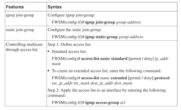
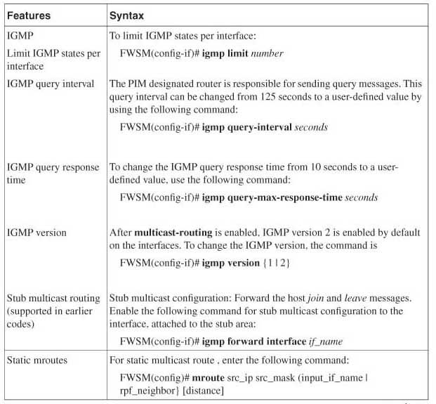
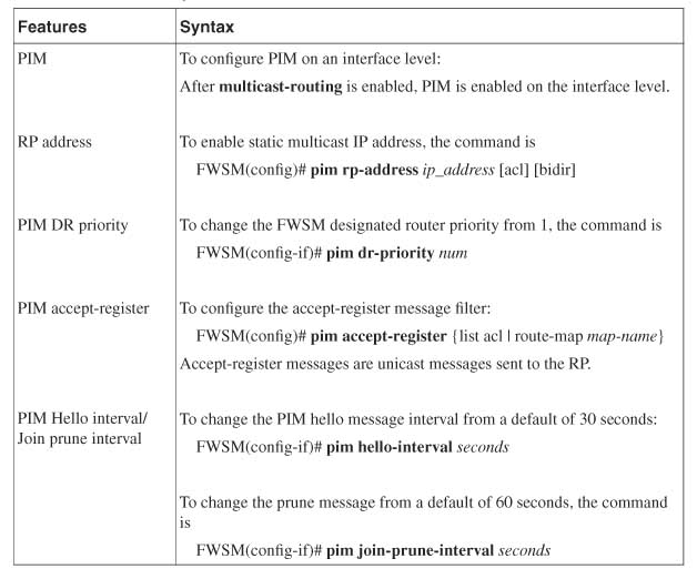
Table 16-1 shows the different multicast features and the support in the 3.x code release for FWSM.
Table 16-1 Multicast Feature Matrix for FWSM 3.x Code Release
There are different ways to support multicast traffic across the FWSM:
1 For the 3.x code release or later, use the FWSM in the single context routed mode. The FWSM can participate as a PIM router. It can also have an RP configuration. The RP configuration is really not recommended from a design perspective because troubleshooting and operational complexity increases.
2 GRE passes the multicast traffic through the tunnel. This is used as a solution quite often. The FWSM does not need a special configuration for configuring multicast. However, special configuration is needed in the FWSM to allow GRE packets to pass through the FWSM. The routing at the Layer 3 device that sources and terminates the GRE needs to be configured, to verify if the multicast traffic takes a correct RPF interface toward the source, receivers, and the RP. GRE can be used for multiple context routed mode. In this method, the FWSM does not inspect the multicast packet encapsulated in the GRE header.
3 In transparent firewalls through ACLs, the firewall passes the traffic in single context and multiple context modes. In the 3.1 code version or later, the performance has been optimized for this configuration.
4 When policy-based routing (PBR) is configured on Layer 3 first hop devices to the FWSM, the PBR will divert the traffic from the FWSM. Configuring multiple context modes for the multicast pass-through with PBR will need careful study of multicast congruency. Sometimes this might become a complex scenario to understand and troubleshoot.
5 The FWSM can be configured as a stub network to pass the IGMP query to the upstream interface for the firewall. The FWSM does not participate in the PIM messages.
FWSM with the 3.x code version or later supports multicast in different modes. This facilitates better integration of the firewall in different parts of the network.
Configuration Methods
This section covers the common configuration methods to pass the multicast traffic through the FWSM. The following are three common ways of configuring:
• Multicast through firewall in single context routed mode
• Multicast through firewall via GRE
• Multicast through transparent firewall in multiple context mode
Method 1: Configuration Example for Multicast Through Firewall in Single Context Routed Mode
To understand method 1, refer to Figure 16-1, which illustrates a configuration example of multicast through single context routed mode.
Figure 16-1 Configuration Example of Multicast Through Single Context Routed Mode in FWSM
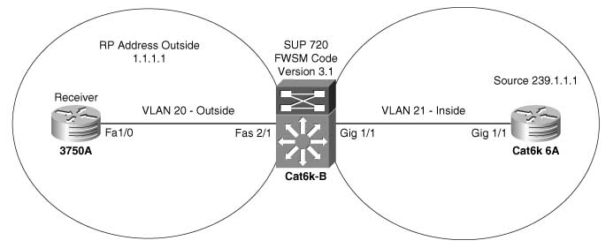
Example 16-1 shows the configuration of multicast through FWSM using the 3.1 code release. The FWSM mode is in single context routed mode. The RP’s IP address in this example is 1.1.1.1 and is on the outside interface of the FWSM. The receiver is on the outside interface and the source is on the inside interface of the FWSM. This example replicates the data center environment, where the source is on the inside interface connecting the data center and the receivers, and RP is at the outside interface of the data center. The RP can also be on the inside interface of the data center, and the FWSM can also participate as an RP. This may require detailed discussion between the security and networking teams to resolve potential operational issues.
Example 16-1 Configuration Example of Multicast Through Single Context Routed Mode in FWSM (Code Version 3.1)
Example 16-1 Configuration Example of Multicast Through Single Context Routed Mode in FWSM (Code Version 3.1) (Continued)
The show mroute command verifies the multicast state on the FWSM:
Verify (*,G),(S,G) state, RP information, and the flags. Explanation of multicast flags is beyond the scope of this book.
Method 2: Configuration Example for Multicast Through Firewall via GRE
To understand method 2, refer to Figure 16-2, which illustrates a configuration example for multicast through firewall via GRE.
Figure 16-2 Configuration Example for Multicast Through Firewall via GRE

This is another method for multicast to traverse through the FWSM. The pass-through of GRE traffic will need careful configuration on the routing part for congruency and RPF checks for multicast reachability. The FWSM has to be configured for reachability of unicast routing flow, between the two security zones. FWSM should have ACL configuration to allow GRE packets to traverse the FWSM. Example 16-2 shows the configuration to achieve multicast through FWSM via GRE.
PFC3bofcat6kB: This is the next hop device connected to the FWSM and has the configuration of the GRE tunnel and the receiver at the outside security domain.
Example 16-2 Configuration Example for Multicast Through Firewall via GRE
Firewall at Cat6kB (FWSM configuration): For passing GRE, ACL configuration is needed. No special multicast configuration is needed at the FWSM.
Cat6k6a: This is the next hop Layer 3 device for the FWSM at the inside security domain and is also configured as an RP.
E-R3745-B: Router configured with a receiver at the inside security domain
Method 3: Configuration Example for Multicast Through Transparent Firewall in Multiple Context Mode
To understand method 3, refer to Figure 16-3, which illustrates a configuration example of multicast through a transparent firewall in multiple context mode.
Figure 16-3 Configuration Example of Multicast Through Transparent Firewall in Multiple Context Mode

In this example, the FWSM is in multiple context mode. The contexts of the FWSM are configured for transparent mode. In multiple context mode, the support for multicast is achieved through transparent firewall. The RP is in the inside security zone. The FWSM is running code version 3.1. The FWSM does not need any configuration, except ACL entries. In the 3.1 code version or later, the performance is optimized for this configuration.
Example 16-3 shows the support of multicast in multiple context mode using transparent firewall.
Example 16-3 Configuration of Multicast Through Transparent Firewall in Multiple Context Mode
Context A configuration:
! To Access context A
FWSM# change to context A
FWSM/A# show run
! Firewall is in transparent mode
firewall transparent
hostname A
enable password 8Ry2YjIyt7RRXU24 encrypted
names
!
interface Vlan30
nameif outside
bridge-group 1
security-level 0
!
interface Vlan31
nameif inside
bridge-group 1
security-level 100
! For management purposes, have an IP address assigned to the BVI
interface BVI1
ip address 10.1.1.100 255.255.255.0
!
passwd 2KFQnbNIdI.2KYOU encrypted
! Access list in this example is not specific, you can use multicast source and
! destination specific access list defined, to be more specific
access-list 100 extended permit ip any any
access-list 100 extended permit udp any any
access-list 101 ethertype permit bpdu
mtu outside 1500
mtu inside 1500
monitor-interface outside
monitor-interface inside
no asdm history enable
arp timeout 14400
access-group 101 in interface outside
access-group 100 in interface outside
access-group 100 out interface outside
access-group 101 in interface inside
access-group 100 in interface inside
access-group 100 out interface inside
route outside 0.0.0.0 0.0.0.0 10.1.1.1 1
telnet 10.1.1.2 255.255.255.255 inside
telnet timeout 5
ssh timeout 5
!
class-map inspection_default
match default-inspection-traffic
!
policy-map global_policy
class inspection_default
inspect dns maximum-length 512
inspect ftp
inspect h323 h225
inspect h323 ras
inspect rsh
inspect smtp
inspect sqlnet
inspect skinny
inspect sunrpc
inspect xdmcp
inspect sip
inspect netbios
inspect tftp
!
service-policy global_policy global
Cryptochecksum:ac2c109d3861e051064dbaa9f777dfd7
: end
PFC3bofcat6kB: Router at the outside security domain
PFC3bofcat6kB# show run
firewall multiple-vlan-interfaces
firewall module 4 vlan-group 2
firewall vlan-group 2 30-34
ip subnet-zero
!
! Enable multicast on the router
ip multicast-routing
!
vlan 10,20-24,30-31,34
! For testing, you can use igmp join-group to have the Loopback 200 act as a receiver
! for 239.1.1.3. Note that the traffic will be process switched. PIM sparse mode
! should be enabled on the interface.
interface Loopback200
ip address 10.1.50.1 255.255.255.255
ip pim sparse-mode
ip igmp join-group 239.1.1.3
! Connects to the FWSM outside interface and has pim sparse mode enabled
interface Vlan30
ip address 10.1.1.1 255.255.255.0
ip pim sparse-mode
! Configure the RP’s IP address.
ip pim rp-address 1.1.1.1
PFC3bofcat6kB#
cat6k6a: Router at the inside security domain of the FWSM
cat6k6a#show run
hostname cat6k6a
! Enable multicast routing
ip multicast-routing
!
! Configure IP address for the RP (1.1.1.1), located at the inside security domain
interface Loopback0
ip address 1.1.1.1 255.255.255.255
ip pim sparse-mode
!
interface GigabitEthernet1/1
switchport
switchport access vlan 31
no ip address
!
interface FastEthernet2/1
ip address 10.1.3.2 255.255.255.252
ip pim sparse-mode
! Enable PIM on all the interfaces to maintain congruency
interface Vlan31
ip address 10.1.1.2 255.255.255.0
ip pim sparse-mode
! Configure RP’s IP address
ip pim rp-address 1.1.1.1
cat6k6a#
In multiple context mode, transparent firewall is the best way to make the multicast packet pass through the FWSM. No special configuration is required in the FWSM. ACL is configured to allow multicast traffic to pass through the FWSM. In this example, the configuration in Layer 3 routers is simple. The transparent mode fits in an environment where a need exists for multiple context mode and multicast support.
Summary
This chapter covers the essential elements of multicast technology. Most of the features for multicast technology are supported in the FWSM 3.x code release. This chapter gives design options available to the reader. Multicast is supported in the single context routed mode, and FWSM takes part in the multicast state distribution tree. For multiple context mode, transparent firewall is an option, where the FWSM inspects the packet flow for the multicast stream.