
Chapter 24 FWSM 4.x Performance and Scalability Improvements
The release of the 4.x code train offers some major improvements in performance and scalability. Trusted Flow Acceleration allows flows to bypass the Firewall Services Module (FWSM), achieving line-rate performance. The combination of the FWSM along with the Programmable Intelligent Services Accelerator (PISA) adds a new level of traffic inspection. The change in memory provisioning for both partitions and rule allocation has greatly improved how resources can be divided. Access list optimization also helps to improve the way that memory is utilized by consolidating overlapping access lists.
Increasing Performance by Leveraging the Supervisor
One of the most significant features to be released with the 4.x code train is the capability to offload flows to the supervisor, called Trusted Flow Acceleration. This capability dramatically increases the throughput of predefined types of traffic and requires a minimum code of 12.2(33)SXI on the supervisor.
Prior to Trusted Flow Acceleration, all traffic was required to flow through the FWSM; refer to Chapter 2, “Overview of the Firewall Services Module,” for details. With the addition of Trusted Flow Acceleration, particular types of traffic defined by an access list can now bypass the FWSM entirely.
You may be asking yourself how this feature works. To get a better idea, the following list will give you an understanding of the packet flow:
1 The FWSM must first be configured for supervisor acceleration. This will function in either single or multiple context routed mode, but it cannot be in transparent mode, and the interfaces cannot be shared with interfaces on other contexts. Also, multiple FWSMs are supported in the same chassis.
2 When Trusted Flow Acceleration is configured, the supervisor takes ownership of the MAC address of the FWSM.
3 When a new session is initiated, it will go to the supervisor because the supervisor has ownership of the MAC address. Because no session entries exist, the supervisor redirects the connection to the FWSM.
4 The redirected traffic to the FWSM must match a predefined access list, which has been associated with the acceleration policy for that traffic to qualify for acceleration.
5 For TCP flows, the FWSM monitors the session for the completion of the three-way handshake. For User Datagram Protocol (UDP) flows, the FWSM watches for the return traffic.
6 Upon completion of a TCP or UDP session, the FWSM creates a flow entry on the supervisor.
7 Additional traffic from that session entering the host-chassis will now have a hardware entry and consequently bypass the FWSM.
Trusted Flow Acceleration takes advantage of NetFlow Ternary Content Addressable Memory (TCAM) space to create accelerated paths. TCAM space is specialized memory designed to provide high-speed forwarding lookups.
NOTE | TCAM space is specialized memory designed to provide high-speed forwarding lookups. |
The following example shows how to configure the FWSM for supervisor acceleration in multiple-context mode and monitor the results. Use Figure 24-1 to see the traffic flow from a graphical perspective.
Figure 24-1 Trusted Flow Acceleration
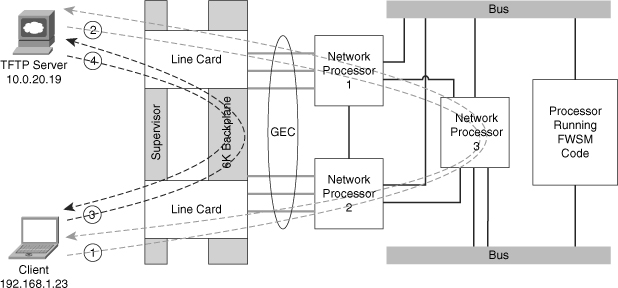
As long as traffic is flowing between the client and server, the packet (Pkts) and byte (Bytes) counter will continue to increment until the download is complete. You should also see that there is both a client-to-server connection and a server-to-client connection, and both are accelerated. If this was not the case, and the FWSM just saw the returning traffic, the connection would be dropped.
There are some additional considerations when deploying Trusted Flow Acceleration. When designing an infrastructure for high-availability and using Stateful Switchover (SSO), Route Processor Redundancy (RPR), and FWSM failover, all the flows need to be reestablished. Furthermore, the following features are not supported:
• Asymmetric routing
• DCF-enable line cards
• Multicast routing
• Shared interfaces
• Stateful failover
• Transparent firewall (single or multiple context)
• Virtual switching system (VSS)
CAUTION | When acceleration is used, none of the inspection engines on the FWSM are used, and TCP state and sequencing is not checked. Additionally, this feature is available only when the FWSM is in a “routed” mode. All packets that are fragmented have an IP option set or are exceptions, such as packet errors, are also sent to the FWSM. |
Trusted Flow Acceleration can be used for large file copies, backup traffic, bulk transfers, and so on, and can even be used when Network Address Translation (NAT) and/or Port Address Translation (PAT) is configured on the FWSM. With this feature turned on, there is no TCP sequence number or state information tracking. Application inspection is also not supported. With either the supervisor or FWSM failing, session information is not maintained and needs to be reestablished. Supervisor acceleration would be extremely beneficial in the datacenter but should be avoided where “untrusted” devices exist—for example, when connecting to the Internet.
Using the PISA for Enhanced Traffic Detection
PISA is a hardware subsystem of the Supervisor 32. The PISA has the capability to detect/classify protocols, and consequently make decisions on the FWSM to forward or deny traffic can be applied by application type. The PISA uses Network-based Application Recognition (NBAR) and Flexible Packet Matching (FPM) to classify traffic. Both NBAR and FPM use a process of “deep” packet inspection to determine traffic types. This looks beyond Layer 4 ports and into the data portion of the packet; therefore, applications using nonstandard ports can be detected. The minimum supervisor code requirement is 12.2(18)ZYA.
The following example uses Figure 24-2. As traffic begins to flow through the PISA, it may take several packets to identify and classify the traffic, depending on the application type. When the type of traffic is determined, the PISA encapsulates those packets in the pseudo-Generic Routing Encapsulation (pseudo-GRE) tunnel and forwards it to the FWSM. The pseudo-GRE headers add 32 bytes, so jumbo Maximum Transmission Units (MTU) larger than 1500 byte frame support should also be enabled. The FWSM and PISA must have a Layer 2 adjacency when the FWSM receives the packet; otherwise, it will be discarded. The FWSM strips the pseudo-GRE header and processes the packet in the fast-path according to how it was classified by the PISA, thereby providing the best possible throughput. The exception to this is for the first packet in a flow. In this case, it must pass the configured access list and/or other rules applied.
Figure 24-2 PISA Deployment

The fact that SUP-32+PISA is generally deployed at the access layer, and FWSM in the distribution or core, allows firewall security policies to be determined after classification and marking. This kind of deployment that uses PISA for application recognition and FWSM for policy control makes a compelling integrated story.
NOTE | The connection between the host-chassis supporting the FWSM and the chassis with the Sup32/PISA should have jumbo frame support enabled. |
There are two possible deployment scenarios to configure protocol discovery for the FWSM and Supervisor32 with a PISA (Sup32/PISA), which are Layer 3 (routed) and Layer 2 (switched) modes.
In Layer 3, or routed-access mode, the access ports are in different VLANs. The Layer 3 next hop is defined as a Switched Virtual Interface (SVI) on the access switch with the Sup32/PISA. The Sup32/PISA has a separate VLAN uplink connection to the FWSM in the upstream switch. Protocol discovery and port tagging will be done on the access-layer VLAN. All egress packets to the FWSM will be tagged leaving the Sup32/PISA switch.
NOTE | The Sup32/PISA and FWSM must be in the same VLAN. |
Layer 2, or switched mode, can be configured using three methods. These modes are very similar in that there is a Layer 2 connection from the access layer (client access) and the FWSM. The difference is determined where the protocol inspection is performed. Protocol discovery can be done on the client side (downstream), on the FWSM side (upstream), or on the shared VLAN between the client and FWSM.
The following example uses a routed-access design, as shown in Figure 24-3.
Figure 24-3 PISA Layer 3 Solution
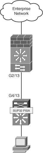
Step 1 | Protocol discovery will be configured on the uplink of the Sup32/PISA switch. In this example, you will see GigabitEthernet4/13, as shown next: |
| interface GigabitEthernet4/13 |
Step 2 | To determine whether protocol-discovery is working, use the show ip nbar protocol-d interface g4/13 top-n command on the Sup32/PISA switch. As you can see from the output, the PISA is doing its job. |
| sup32_pisa#show ip nbar protocol-d interface g4/13 top-n |
Configure the interconnect on the host-chassis with the FWSM as follows: | |
| interface GigabitEthernet2/13 |
Step 4 | The interface configuration on the FWSM includes the name, security level, and IP address, as shown: |
| interface Vlan175 |
Step 5 | Configure an access list used to identify interesting traffic. |
| access-list PROT-INSPECT extended permit tcp any any |
Step 6 | Create a class map and apply the previous access list. |
| class-map CLASS-INSPECT |
Step 7 | Add a policy map statement matching the class map and defining which traffic types are to be permitted or denied. |
| policy-map POLICY-INSPECT |
Step 8 | Apply the policy map to the inside interface. |
| service-policy POLICY-INSPECT interface inside |
Step 9 | Verify that the policy map is applied. |
| FWSM# show service-policy interface Inside |
Check that the protocol inspection is taking place, using the show np 1 pisa and show np 2 pisa commands. The output shows that you are indeed receiving GRE packets. Traffic is also being permitted and denied. | |
| FWSM# show np 1 pisa ---------------------------------------------------------------------- Fast Path PISA Statistics Counters (NP-1) ---------------------------------------------------------------------- PISA GRE tagged packets received : 1983455 PISA tagged packets hitting a session : 1983455 PISA tagged packets permitted : 1792111 PISA tagged packets permitted first UDP : 0 PISA tagged packets denied : 191344 PISA tagged packet not hitting PISA session : 0 FWSM# show np 2 pisa ---------------------------------------------------------------------- Fast Path PISA Statistics Counters (NP-2) ---------------------------------------------------------------------- PISA GRE tagged packets received : 1968260 PISA tagged packets hitting a session : 1968260 PISA tagged packets permitted : 1778413 PISA tagged packets permitted first UDP : 0 PISA tagged packets denied : 189847 PISA tagged packet not hitting PISA session : 0 |
The PISA offers another level of inspection not found on the FWSM. By classification of traffic before it gets to the FWSM, it also helps the FWSM predefine how specific application types should be treated. Using the FWSM in conjunction with a PISA will notably improve the performance of the FWSM and the overall security posture of your organization.
Improving Memory
Rigid allocation of memory with code versions prior to 4.x required extensive thought and planning. The flexibility offered with 4.x code makes the management of the FWSM significantly easier.
Partitioning Memory
The 4.x code now has the capability to have memory partitions of unique sizes. For a quick refresher on what memory partitions are, see Chapter 5, “Understanding Contexts.” Figure 24-4 shows how memory was allocated by dividing it equally among the total number of partitions. This posed some challenges for contexts associated with partitions that required additional resources. It was difficult to organize them in a manner that would take advantage of those resources efficiently. This is not the case with the 4.x code. Figure 24-4 shows how the allocation of resources in memory partitions has changed.
Figure 24-4 Memory Partition Changes

NOTE | The FWSM must be rebooted for memory allocation changes to take effect. |
FWSM# sh resource partition
Bootup Current
Partition Default Partition Configured
Number Size Size Size
-----------+---------+----------+-----------
0 19219 19219 19219
1 19219 1024 1024
2 19219 19219 19219
3 19219 19219 19219
4 19219 19219 19219
5 19219 19219 19219
6 19219 19219 19219
7 19219 19219 19219
8 19219 19219 19219
9 19219 19219 19219
10 19219 19219 19219
11 19219 19219 19219
backup tree 19219 19219 19219
-----------+---------+----------+-----------
Total 249847 231652 231652
Total Partition size - Configured size = Available to allocate
249847 - 231652 = 18195
Partition allocating gives you a great deal of flexibility. Partitions that require fewer resources can now be reduced, consequently providing additional resources for other partitions.
Reallocating Rules
Within each one of the memory partitions is a subset of resources allocated to rules. These resources can also be divided according to the specific needs of each partition. Figure 24-5 shows how rules can be assigned within each of the memory partitions.
Figure 24-5 Rule Reallocation

To view the resources allocated to a specific partition, use the show resource rule partition number command, as shown in Example 24-1.
Example 24-1 Displaying Partition Resource Allocation
As you can see from the output, 19,219 resources can be allocated among the eight groups, which are
• Policy NAT: Specifies the number of policy NAT entries.
• ACL: Sets the number of ACL entries, only limited by system resources.
• Filter: Identifies the number of filter rules.
• Fixup: Defines the number of application-inspection rules, also know as a fixup.
• Est Ctl: Signifies the number of established control commands.
• Est Data: Specifies the number of established data commands.
• AAA: Defines the number of AAA rules.
• Console: Identifies the total number of rules that apply to the FWSM in regard to management, including HTTP, Telnet, SSH, and ICMP.
From the output in Example 24-2, you can determine that additional ACL entries are needed.
Example 24-2 ACL Resource Limit Reached
There is now enough space to add some more ACL entries, without a reboot of the FWSM!
From the previous example, you can see how valuable it is to be able to dynamically modify the rule allocation. You may also consider lowering the size of the resources within a partition. That way you can easily adjust them without having to reboot the FWSM when you hit a limit. This will give you some time to consider more permanent changes by modifying memory partitions.
Optimizing ACL
Because memory space is a limited resource, and ACLs are the main contributor to the depletion of resources, the ACL optimization feature is a very welcome addition. As entries to access lists are added, removed, or modified, keeping track of all the changes and manually organizing them would be a management nightmare. Fortunately, the ACL optimization feature will review the existing ACLs and minimize the configuration, consequently saving memory resources.
The configuration in Example 24-3 contains an access list with 255 entries. Of those entries, 254 are host specific and one specifies the entire range.
Example 24-3 ACL Optimization
From the output in Example 24-3, there is a total of 255 ACL entries, 254 of which could be eliminated because they are more specific entries.
Step 1 | To have the FWSM optimize the access list, enter the following command: |
| FWSM/Cust-B(config)# access-list optimization enable |
Step 2 | At this point, the access lists are optimized but not applied. To see what the FWSM did to the access list, use the show access-list ACL_NAME optimization command, as follows: |
| FWSM/Cust-B(config)# show access-list ACL_OPTIMIZATION optimization |
| This access list may be a little unrealistic (okay, very unrealistic) but you get the idea of how it works. Because each of the host entries are a subset of the network, they were combined into a single access list. The reduction was an amazing 99 percent. |
Step 3 | You are not done yet! The access list has been optimized but not applied. You can copy the optimized access list to disk, flash, FTP or TFTP server, a system file, the startup-config, or in this example, the running-config as shown by the following command: |
| FWSM/Cust-B(config)# copy optimized-running-config running-config |
| Chances are, the first few times you optimize the access list entries you will review them in detail, just like when you didn’t trust your first calculator. |
Now that the access list has been applied, the configuration has changed to the following single-line ACL: | |
| FWSM/Cust-B(config)# show access-list ACL_OPTIMIZATION |
You may want to periodically use the optimization feature to check that you are not using up too much memory space for access lists. This feature will be a huge timesaver from the “old-fashioned” way of manually checking. Sometimes, features that automate processes tend to enable poor documentation habits; be sure to keep your records up to date to enable quicker troubleshooting and access to information for auditing.
Summary
Supervisor acceleration is one of the most significant features released in the 4.x code train. The capability to get “line-rate” throughput per flow is a drastic improvement over a 1-gigabit limit per flow. Leveraging the PISA to inspect traffic flows prior to the FWSM also increases throughput performance. Memory partitions, rule allocation, and ACL optimization help to make the best use of resources and grow as network requirements continue to grow. Understanding the intricacies of each of these features in this chapter will undoubtedly make you more successful in the design, implementation, and management of the FWSM and give you a better understanding of where the optimal placement of the FWSM should be in your network.