CHAPTER 11
Switch Features
The CompTIA Network+ certification exam expects you to know how to
• 1.6 Explain the use and purpose of network services
• 2.1 Compare and contrast various devices, their features, and their appropriate placement on the network
• 2.2 Compare and contrast routing technologies and bandwidth management concepts
• 2.3 Given a scenario, configure and deploy common Ethernet switching features
• 3.3 Explain high availability and disaster recovery concepts and summarize which is the best solution
• 4.4 Compare and contrast remote access methods and security implications
• 5.2 Given a scenario, troubleshoot common cable connectivity issues and select the appropriate tools
To achieve these goals, you must be able to
• Define the capabilities and management of managed switches
• Configure and deploy VLANs
• Implement advanced switch features
So far in this book we’ve looked at networks in a rather simplistic way. First, we explored network topologies. Second, we’ve seen a number of devices whose functions neatly align with the OSI model. From cabling humming along at Layer 1, switches at Layer 2, and routers at Layer 3, each performs specific services without overlap. This is a great way to begin learning about networking, but it’s not a complete view of how many networks function. It’s time to go into more depth.
This chapter starts by exploring how to manage devices that handle switching, security, and more. The second portion examines VLANs: technology built into better switches that segments a single network into multiple virtual networks. The chapter finishes with a discussion of multilayer switches—boxes that do pretty much everything from Layer 1 all the way to Layer 7.
Test Specific
Switch Management
The simple switches discussed so far in this book are also called unmanaged switches, which basically means techs have no control over how they work beyond what devices to plug in and which ports to use. This “simple” work is critical—it’s the device’s purpose—so the heavy lifting is traditionally done in highly optimized hardware. These optimized components are also known as the data plane or the forwarding plane.
Less-simple managed switches have an operating system (running on hardware separate from the data plane) that enables device configuration. The device also uses the OS and hardware resources to run software that implements additional features. This extra layer of software and the hardware that supports it are also known as the control plane. What’s there to configure? Pretty much everything in this chapter! Let’s start with a look at how to access the configuration interface.

NOTE This distinction between the data and control planes doesn’t just apply to switches. You may see these terms applied to other hardware devices such as routers, firewalls, and sometimes even entire networks. Likewise, these methods of switch management apply to any type of managed device (such as routers).
You can connect to a managed switch to tell it what you want it to do. Exactly how you do this varies from switch to switch, but generally there are three ways:
• Directly plug into a serial interface and use a virtual terminal program to connect to a command-line interface. Nowadays, you’d use a serial-to-USB converter to connect a laptop to the console port on the switch.
• Attach the switch to the network and then use a virtual terminal over SSH to connect to the same command-line interface.
• Connect the switch to the network and use the switch’s built-in Web interface.
Let’s look at the steps involved in each method.
First, many managed switches have a special serial port called a console port. Plug a laptop (or other computing device) into the console port on the back of the switch (Figure 11-1). Then, run a terminal program like PuTTY to access the command-line interface on the switch. As long as you speak the language of the switch’s command prompt, you’re good to go. It’s very common to use a console port for initial configuration of a new managed switch.
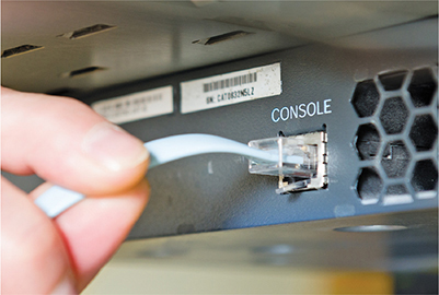
Figure 11-1 Plugging into a managed switch’s console port using a console cable
The second and third methods require the managed switch to be connected to the network and have an accessible IP address. Connect to the switch over the network and run some sort of software—either PuTTY or a Web browser—to manage the switch.
Wait! It’s a switch. Switches that we’ve discussed in the book so far operate at Layer 2 of the OSI model. IP addresses don’t show up until Layer 3. Here’s the scoop in a nutshell. A managed switch needs an IP address to enable configuration on Layer 3.
This means a new, out-of-the-box managed switch has all the same configuration issues a new router would have. Many new managed switches have a default IP address (but you should assign an IP address that’s applicable to your network). Others require a proprietary configuration utility that discovers by MAC address. Switches with default IP addresses have default usernames and passwords (but you should change those!). Both types have a bunch of other default settings that you’ll probably want to change once you know what they mean.
Like any IP device, a managed switch needs good, basic maintenance. One example would be updating the firmware. Managed switches support firmware updates over the Internet. That’s a nice idea, but it means your switch needs a default gateway, a DNS server, and so forth to be able to access content over the Internet.

EXAM TIP You configure a default gateway on a switch by telling the switch the IP address of the router.
Access Management
As you might imagine, it would be scary to let unauthorized people have access to your switch management configuration interface. When you configure a switch over the network—we call this in-band management—anyone who knows the IP addresses of the managed devices can access them if they know or guess the username and password. To reduce this risk, it’s common to dedicate one port on every managed device as a management port. You can do interface configuration only by directly connecting to that port.
Alternatively, you can connect all those dedicated ports into a switch that’s totally separate from the rest of the network, which will prevent unauthorized access to those ports. This is one example of out-of-band management.
If you have a switch in a far-flung location, it’ll be much easier to manage with some method of remote management. Switches with Web management interfaces often provide a well-protected HTTPS/management URL that administrators can use to log into the switch via the Internet (another example of in-band management).
EXAM TIP Look for a question that asks you to compare in-band vs. out-of-band management, specifically in the context of securing remote access. In-band management means managing the switch from the same network that moves data (whether you connect locally or remotely). Out-of-band management means managing the switch from outside the network, usually via a separate network just for managing and monitoring.
Port Configuration
Over the years, switches have accumulated a number of situational per-port features that were built to make lemonade out of lemons when a network runs into some specific problems. The defaults are usually fine; we only fiddle with these to address specific problems (and, even then, only if they don’t create more problems than they fix). Let’s look at the settings for speed, duplex, flow control, and jumbo frames.
Before you start changing port settings, check the current status of the interface. You can do this in many ways, though most techs use the command line. Here are three command-line options on three different switches from three different providers. The command-line syntax and options differ between vendors and even OS versions. A lot of the commands are very similar, but you’ll have to spend a little time getting used to the syntax and options available on any devices with which you work.
Figure 11-2 shows the output for show interfaces on all three switches (with the settings we’re focusing on here highlighted when they are present).
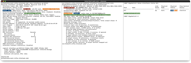
Figure 11-2 Interface status in Juniper JunOS (left), Cisco IOS (middle), and Ubiquiti EdgeSwitch (right)
EXAM TIP The CompTIA Network+ objectives call out some basic network platform commands—show config, show interface, and show route. These commands can be a big help when it comes to troubleshooting, so keep an eye out for all of them in Chapter 21!
Modern switches enable you to provide manual support for older hardware in terms of controlling network speed and duplex settings. A typical “Gigabit” switch, for example, automatically supports 1000-Gbps connections and the slower 100-Mbps “Fast Ethernet” connections and the super slow 10-Mbps connections. In some rare circumstances, you can set a port manually to run at a specific speed.
Some truly ancient wired devices operate at half duplex, meaning they can send or receive, but not both at the same time. (The latter is full duplex.) The default switch port setting is autosensing, just like with speed, but you can force a port to half duplex if necessary to support an old device.
In theory, flow control can help with situations like a host that can’t keep up with the flow of traffic. It enables the host to send an Ethernet PAUSE frame, which asks the switch to hold up for some amount of time so the host can catch its breath. If the switch can, it’ll buffer transmissions until the pause expires, and then start sending again. If the host catches up early, it can send another PAUSE frame with a delay of zero to ask the switch to resume. In practice, flow control can cause latency trouble for modern real-time applications such as VoIP, and the same needs are usually met by QoS (which we’ll take a closer look at later in the chapter).
Some special-purpose networks, such as those optimized for reading and writing to storage devices (we’ll take a closer look at these in Chapter 16), require a lot of throughput. An inexpensive way to boost their performance is to enable them to use jumbo frames larger than the normal 1500 byte payload limit specified by IEEE 802.3, because it helps improve the payload-to-overhead ratio. You can’t just enable jumbo frames for all purposes, especially if you’re connected to the Internet. The rest of the WAN won’t respect your hefty frames, and you’ll just end up with fragmentation and dropped packets that actually hurt performance or prevent connections altogether.
Port Security
In a general sense, port security means to lock switch ports to a specific MAC address. The port will only work with a specific computer after configuration. This process is pretty time-intensive in larger networks.
With Cisco switches, you can configure MAC addresses to be sticky—also called persistent MAC by other switch makers. The MAC addresses can be dynamically learned or manually configured, stored in the address table, and added to the running configuration. If these addresses are saved in the configuration file, the interface does not need to dynamically relearn them when the switch restarts. Although sticky secure addresses can be manually configured, it is not recommended.
Virtual LANs
Today’s LANs are complex places. It’s rare to see any serious network that doesn’t have remote incoming connections, public Web or e-mail servers, wireless networks, and a string of connected switches. Leaving all of these different features on a single broadcast domain creates a tremendous amount of broadcast traffic and creates security challenges. What if you could segment the network using the switches you already own? A virtual local area network (VLAN) enables you to segment a physical network into multiple discreet networks without having to add additional hardware.
EXAM TIP The CompTIA objectives use the term data virtual local area network (VLAN) to describe the standard VLANs discussed here. This differentiates them from voice VLANs, discussed later in this chapter.
To create a VLAN, you take a single physical broadcast domain made up of one or more switches and chop it up into multiple broadcast domains. This is most simply done by assigning each port to a specific VLAN. VLANs require switches with specific programming to create the virtual networks.
Imagine a single switch with a number of computers connected to it. Up to this point, a single switch creates a single broadcast domain, but that’s about to change. You’ve decided to take this single switch and turn it into two VLANs. VLANs typically get the name “VLAN” plus a number, like VLAN1 or VLAN0275. The devices usually start at 1, although there’s no law or rules on the numbering other than that enterprise switches require four digits (like VLAN0001 rather than VLAN1). In this example, I’ll configure the ports on a single switch to be in one of two VLANs: VLAN1 or VLAN2 (Figure 11-3). I promise to show you how to configure ports for different VLANs shortly, but I’ve got a couple of other concepts to hit first.
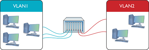
Figure 11-3 Switch with two VLANs
Figure 11-4 shows a switch configured to assign individual ports to VLANs. Managed switches can handle any number of VLANs. Every port starts with the default VLAN, VLAN1, so even if you don’t specify multiple VLANs, you get one by default.
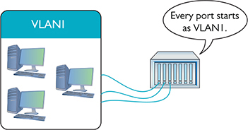
Figure 11-4 Every port is VLAN1 by default.
EXAM TIP Most of the networking industry recommends changing your network’s default VLAN to anything other than VLAN1 to harden your network against attacks that target the default setting. “Change default VLAN” is how this appears in the CompTIA N10-008 exam objectives.
To set up a VLAN on a switch, create one or more VLANs, then assign ports to those VLANs. Any traffic sent from a host plugged into a port for VLAN1, therefore, becomes part of the broadcast domain of VLAN1.
Serious networks usually have more than one switch. Let’s say you added a switch to a simple network. You’d like to keep VLAN1 and VLAN2 but use both switches. You can configure the new switch to use VLAN1 and VLAN2, but you’ve got to enable data to flow between the two switches, regardless of VLAN. That’s where trunking comes into play.
Trunking
Trunking is the process of transferring VLAN traffic between two or more switches. Imagine two switches, each configured with a VLAN1 and a VLAN2, as shown in Figure 11-5.
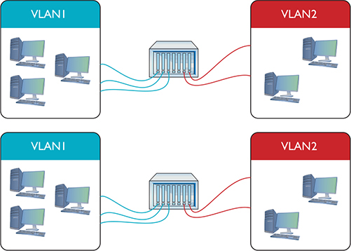
Figure 11-5 Two switches, each with a VLAN1 and a VLAN2
You want computers connected to VLAN1 on one switch to talk to computers connected to VLAN1 on the other switch. Of course, you want to do this with VLAN2 also. To do this, configure a port on each switch as a trunk port, a port on a switch configured to carry all traffic, regardless of VLAN number, between all switches in a LAN (Figure 11-6).
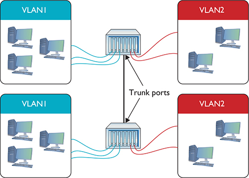
Figure 11-6 Trunk ports
Every Ethernet switch uses the IEEE 802.1Q trunk standard that enables you to connect switches from different manufacturers.
![]()
SIM Check out the excellent Chapter 11 Challenge! Sim, “Trunking,” to test your understanding of trunking. You’ll find it here: https://totalsem.com/008.
Configuring a VLAN-Capable Switch
If you want to configure a VLAN-capable switch, you need a method to perform that configuration. One method uses a console port like the one described in Chapter 7. The most common method is to log into the switch using SSH—not Telnet, because you need security—and use the command-line interface. Once you know what you’re doing, the command line is fast, precise, and scriptable. Alternatively, you can access the switch with a Web browser interface, like the one shown in Figure 11-7.
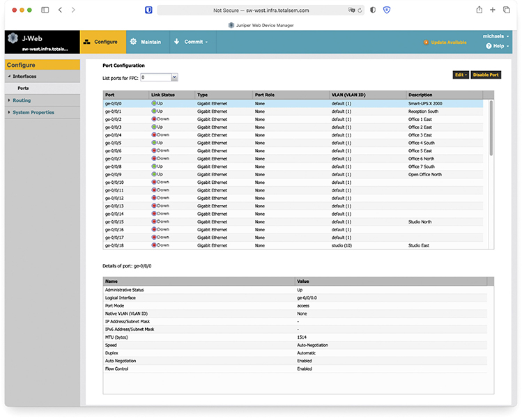
Figure 11-7 Browser interface for a switch
Every switch manufacturer has its own interface for configuring VLANs, but the interface shown in Figure 11-8 is a classic example. This is Cisco Network Assistant, a GUI tool that enables you to configure multiple Cisco devices through the same interface. Note that you first must define your VLANs.
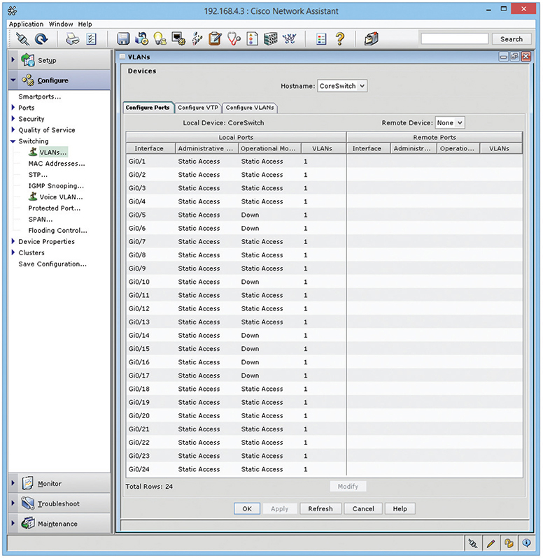
Figure 11-8 Defining VLANs in Cisco Network Assistant
After you create the VLANs, you assign ports to them, a process called VLAN assignment. Assigning each port to a VLAN means that whatever computer plugs into that port, its traffic will be associated with that port’s VLAN ID. (See the following section, “Assigning VLANs and Tagging.”) Figure 11-9 shows a port being assigned to a particular VLAN.
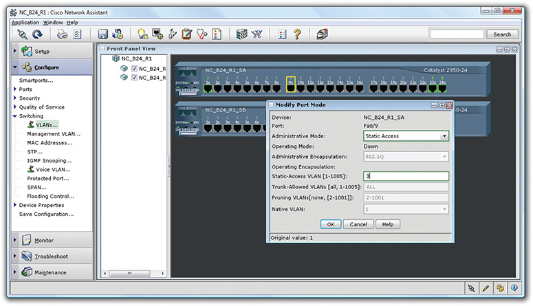
Figure 11-9 Assigning a port to a VLAN
NOTE VLANs based on ports are the most common type of VLAN and are commonly known as static VLANs. VLANs based on MAC addresses are called dynamic VLANs. The latter method is never used these days.
Assigning VLANs and Tagging
When you have a busy network with multiple switches and multiple VLANs, how does a frame from a host in VLAN100 make it to a destination host in the same VLAN? What if the hosts are several switches apart? The key tool that makes this happen is 802.1Q port tagging. An 802.1Q tag is a field tacked on to a frame’s Ethernet header enabling the next switch to associate it with the correct VLAN. You’ll only find tags on frames as they transit trunk lines between switches—not on lines between switches and regular hosts.
Regular hosts plug into access ports (sometimes called untagged ports), standard switch ports that do the work of associating untagged traffic with their assigned VLAN as frames enter the switch. Access ports connect to hosts; trunk ports connect to other trunk ports on other switches.
When the data enters the access port, the switch associates the frames with the appropriate VLAN ID. If the destination host is connected to the same switch, the frames flow to that host’s access port and out over the wire without a VLAN tag. If the destination host connects to a different switch, the initial switch sends the frames out its trunk port (sometimes called a tagged port). What happens next is determined by how the trunk port is configured.
If the trunk port’s native VLAN—the VLAN ID it associates untagged traffic with—is the same as the VLAN the frame was associated with as it entered the access port, the switch sends the frame along to the next switch without adding a tag. If the frame is part of any other VLAN, then the trunk port adds the 802.1Q tag to the frame and sends it on its way.
Native VLANs exist to provide compatibility with older or simpler non-802.1Q switches, but there is a catch. The native VLAN opens your network to a nasty vulnerability called a double-tagging attack that lets the attacker access VLANs they should not be able to access. For this reason, in modern networks the native VLAN is set to an unused VLAN and the trunk port is configured to tag its native VLAN traffic as well.
VLAN Trunking Protocol
A busy network with many VLAN switches can require periods of intensive work to update. Imagine the work required to redo all the VLAN switches if you changed the VLAN configuration by adding or removing a VLAN. You’d have to access every switch individually, changing the port configuration to alter the VLAN assignment, and so on. The potential for errors is staggering. What if you missed updating one switch? Joe in Sales might wrongly have access to a sensitive accounting server or Phyllis in accounting might not be able to get her job done on time.
Cisco uses a proprietary protocol called VLAN Trunking Protocol (VTP) to automate the updating of multiple VLAN switches. With VTP, you put each switch into one of three states: server, client, or transparent. When you make changes to the VLAN configuration of a VTP server switch, all the connected VTP clients and VTP servers update their configurations within minutes. The big job of changing every switch manually just went away.
NOTE VTP offers VTP pruning, a tool for minimizing broadcast traffic. This can be a very useful tool on larger-scale networks.
When you set a VLAN switch to transparent, you tell it not to update but to hold onto its manual settings. You would use a transparent mode VLAN switch in circumstances where the overall VLAN configuration assignments did not apply. (VTP transparent switches still pass on updates to other switches in the VTP domain.)
NOTE VTP clients can update VTP servers the same way VTP servers update VTP clients. The difference is that VLAN info can only be changed on VTP servers.
Inter-VLAN Routing
Once you’ve configured a switch to support multiple VLANs, each VLAN is its own broadcast domain, just as if the two VLANs were on two completely separate switches and networks. There is no way for data to get from one VLAN to another unless you use a router or a multilayer switch. (See “Multilayer Switches” later in the chapter for the scoop on these devices.)
The process of passing traffic between two VLANs is called inter-VLAN routing. In principle, implementing inter-VLAN routing could be done using a router with multiple ports. Figure 11-10 shows a very simple example with two VLANs connected by a single router. Note that the router has one port connected to VLAN100 and another connected to VLAN200. Devices on VLAN100 may now communicate with devices on VLAN200.
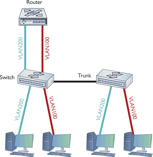
Figure 11-10 One router connecting multiple VLANs
More commonly, you see a router-on-a-stick configuration, which uses a single router interface to connect to multiple VLANs on a switch. The router interface is set up as a trunk port and then broken up into logical subinterfaces for each VLAN. The subinterfaces can handle different or unique Layer 3 information. Figure 11-11 shows a visual example, with eth1 as the physical interface, and eth1.5, eth1.10, and eth1.20 as the subinterfaces.
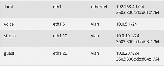
Figure 11-11 Subinterfaces in action
Adding a physical router isn’t a very elegant way to connect VLANs. This forces almost all traffic to go through the router, and it’s not a very flexible solution if you want to add more VLANs in the future. As a result, many VLAN-capable switches also do routing. Figure 11-12 shows an inter-VLAN routing–capable switch, the Juniper EX3400.
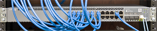
Figure 11-12 Juniper EX3400
From the outside, the EX3400 looks like any other switch. On the inside, it’s a flexible device that not only supports VLANs but also provides routing to interconnect these VLANs.
If the Juniper EX3400 is a switch and a router, on what layer of the OSI seven-layer model does it operate? If it’s a switch, then it works at Layer 2. But routers work at Layer 3. This isn’t an ordinary switch. The Juniper EX3400 works at both Layers 2 and 3 at the same time.
DHCP and VLANs
DHCP is an awesome tool to automate, track, and manage IP address assignments, as you know from previous chapters. Unfortunately, the protocol is limited to a single subnet within a single broadcast domain. By default, DHCP requests (which are broadcasts) can’t pass through a router. So, if you have broken up your network with VLANs and connected those VLANs with routers, you need some method for getting IP addresses and other TCP/IP information to hosts. Unless you want to go back to tediously applying static addresses one at a time!
When a relay agent (CompTIA calls this a DHCP relay—you might remember this from the discussion of DHCP in Chapter 6) is enabled and configured within a router, the router passes DHCP messages across the router interfaces. So now we can use a single DHCP server to serve addresses to multiple networks or subnetworks. Cisco implements DHCP relay through a configuration command called IP helper (the command is technically ip helper-address). IP helper enables DHCP relay support (port 67). It also enables relaying for TFTP (port 69), NTP (port 123), TACACS+ (port 49), DNS (port 53), NetBIOS (port 137), and NetBIOS Datagram (port 138).
Voice VLANs
VLANs optimized for voice data streams—voice VLANs—prioritize voice traffic over data traffic to ensure smooth voice communication. Voice VLANs can use MAC addresses to determine which devices on the network are phones or use VLAN-based tags in the received frame. The switch can prioritize the voice traffic and deprioritize data traffic as specified.
Private VLANs
The point of a network may seem to be interconnecting devices, but there are times when you don’t want hosts on a switch to talk to one another. Think of a hotel where every room has Internet access. You wouldn’t want the guests seeing each other’s traffic—you just want each guest’s Ethernet frames to flow to and from the hotel’s gateway. For situations like this, it’s a best practice to implement Private VLANs.
A Private VLAN only allows traffic from private ports (regular switch ports that are part of the private VLAN) to be switched to the uplink trunk port. It can’t go to any other port on the switch, isolating hosts from each other at Layer 2.
Troubleshooting VLANs
At this level, troubleshooting a new VLAN is mostly about port assignment. If you give an incorrect VLAN assignment to a device, either you won’t be able to see it or that device won’t have access to resources it needs. The fix is the obvious one: change the VLAN assignment.
Multilayer Switches
At this point you must stop thinking (if you still are) that a “switch” always works at Layer 2. A Layer 2 switch forwards traffic based on MAC addresses, whereas a Layer 3 switch (also called a Layer 3 capable switch) forwards traffic based on IP addresses. A Layer 3 switch is a router that does what a traditional router does in software…in hardware. A Layer 3 switch, by definition, is a multilayer switch, functioning at both Layer 2 and Layer 3. From here on out, I will carefully address at what layer of the OSI seven-layer model a switch operates.
The challenge to multilayer switches comes with the ports. On a classic Layer 2 switch, individual ports don’t have IP addresses. They don’t need them. On a router, however, every port must have an IP address because the routing table uses the IP address to determine where to send packets.
A multilayer switch needs some option or feature for configuring ports to work at Layer 2 or Layer 3. Cisco uses the terms switch port and router port to differentiate between the two types of ports. You can configure any port on a multilayer switch to act as a switch port or a router port, depending on your needs. Multilayer switches are incredibly common and support a number of interesting features, clearly making them part of what I call advanced networking devices.
I’m going to show you four areas where multilayer switches are very helpful: load balancing, quality of service, port bonding, and network protection. (Each term is defined in its respective section.) These four areas aren’t the only places where multiplayer switches solve problems, but they are popular (and covered on the CompTIA Network+ exam). Each section covers common use cases, in CompTIA speak, for these devices. In other words, I’ll explain when and where to use each function.
NOTE Any device that works at multiple layers of the OSI seven-layer model, providing more than a single service, is called a multifunction network device.
Load Balancing
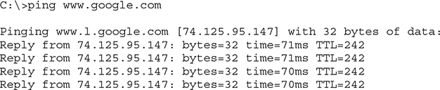
Popular Internet servers are exactly that—popular. So popular that a single system cannot possibly support the thousands, if not millions, of requests per day that bombard them. But from what you’ve learned thus far about servers, you know that a single server has a single IP address. Put this to the test. Go to a command prompt and type ping www.google.com and press ENTER.
A seriously epic site like google.com will handle trillions of search requests per year. Let’s throw hypothetical math into the mix. Imagine 2 trillion requests; the average would be well over 5 billion search requests a day and 60,000 per second. Each of those 60,000 requests might require the Web server to deliver thousands of HTTP segments. A single, powerful, dedicated Web server simply can’t handle that load. A busy Web site often needs more than one Web server to handle all the requests. Let’s say a Web site needs three servers to handle the traffic. How does that one Web site, using three different servers, use a single IP address? The answer is found in something called load balancing.
NOTE Coming to a consensus on statistics like the number of requests/day or how many requests a single server can handle is difficult. Just concentrate on the concept. If some nerdy type says your numbers are way off, nicely agree and walk away. Just don’t invite them to any parties.
Load balancing means making a bunch of servers look like a single server, creating a server cluster. Not only do you need to make them look like one server, you need to make sure that requests to these servers are distributed evenly so no one server is bogged down while another is idle. There are a few ways to do this, as you are about to see. Be warned, not all of these methods require an advanced network device called a load balancer, but it’s common to use one. Employing a device designed to do one thing really well is always much faster than using a general-purpose computer and slapping on software.
DNS Load Balancing
Using DNS for load balancing is one of the oldest and still very common ways to support multiple Web servers. In this case, each Web server gets its own (usually) public IP address. Each DNS server for the domain has multiple “A” DNS records, each with the same fully qualified domain name (FQDN). The DNS server then cycles around these records, so the same domain name resolves to different IP addresses. Figure 11-13 shows a DNS server with multiple A records for the same FQDN.
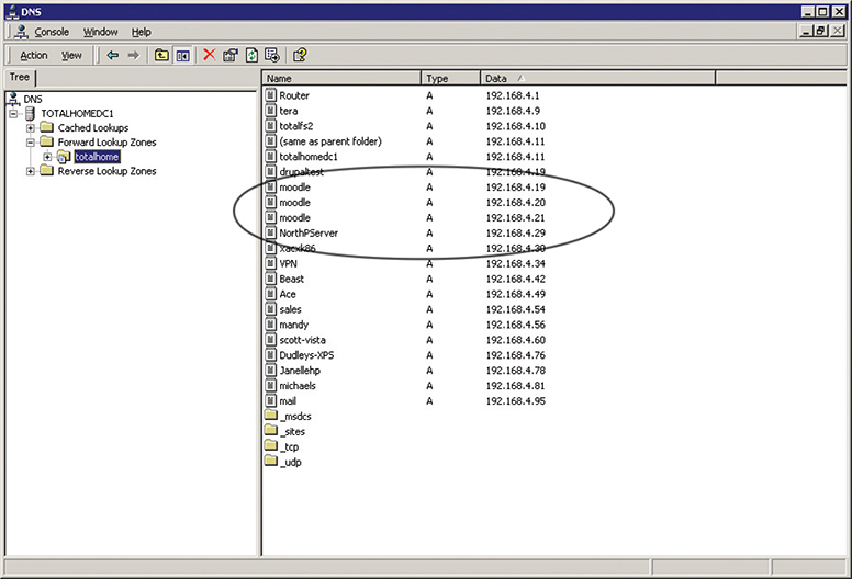
Figure 11-13 Multiple IP addresses, same name
Now that the A records have been added, you need to tell the DNS server to cycle around these names. It should be fairly obvious where to do this. In a Windows DNS server, for example, you’ll select a checkbox to do this, as shown in Figure 11-14.
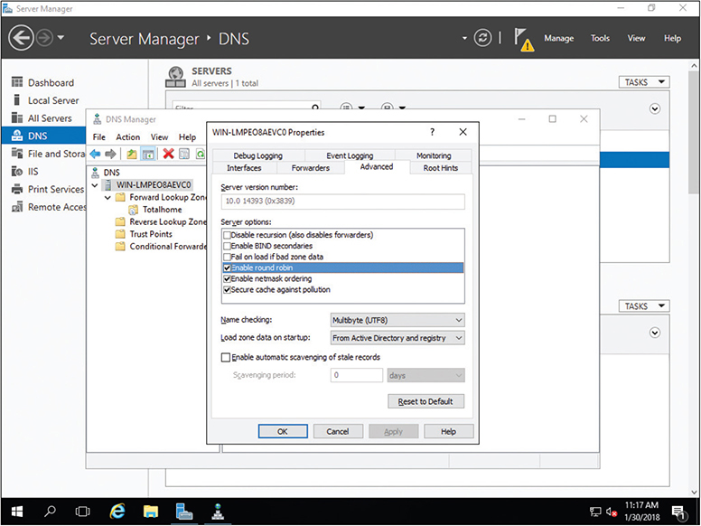
Figure 11-14 Enabling round robin
When a computer comes to the DNS server for resolution, the server responds with all A records. Then next time DNS is queried, all A records are returned but in a different order. This is known as round robin.
The popular BIND DNS server has a very similar process but adds even more power and features such as weighting one or more servers more than others or randomizing the DNS response.
Content Switch
Many multilayer switches handle load balancing by functioning at multiple layers. An alternative is a content switch. Content switches always work at Layer 7 (Application layer). Content switches designed to work with Web servers, for example, can read incoming HTTP and HTTPS requests. With this feature, you can perform very advanced actions, such as handling TLS certificates and cookies, on the content switch, removing the workload from the Web servers. Not only can these devices load balance in the ways previously described, but their HTTP savvy can actually pass a cookie to HTTP requesters—Web browsers—so the next time that client returns, it is sent to the same server.
QoS and Traffic Shaping
Just about any router you buy today has the capability to block packets based on port number or IP address, but these are simple mechanisms mainly designed to protect an internal network. What if you need to control how much of your bandwidth is used for certain devices or applications? In that case, you need quality of service (QoS) policies to prioritize traffic based on certain rules. These rules control how much bandwidth a protocol, PC, user, VLAN, or IP address may use. Figure 11-15 shows the QoS configuration on an Ubiquiti EdgeMAX router, what Ubiquiti calls Smart Queue Management.
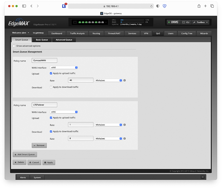
Figure 11-15 QoS configuration (Smart Queue Management) on a router
On many routers and switches, you can implement QoS through bandwidth management, such as traffic shaping where you control the flow of packets into or out of the network according to the type of packet or other rules.
EXAM TIP The term bandwidth shaping is synonymous with traffic shaping. The routers and switches that can implement traffic shaping are commonly referred to as shapers.
Traffic shaping is very important when you must guarantee a device or application a certain amount of bandwidth and/or latency, such as with VoIP or video. Traffic shaping is also very popular in places such as schools, where IT professionals need to control user activities, such as limiting Web usage or blocking certain risky applications such as peer-to-peer file sharing.
Port Bonding
There are times when the data capacity of a connection between a switch and another device isn’t enough to meet demand. Situations like these are encountered regularly in large data centers where tremendous amounts of data must be moved between racks of storage devices to vast numbers of users. Sometimes the solution is simple, like changing from a low-capacity standard like 100-megabit Ethernet to Gigabit Ethernet.
But there are other ways to achieve high-speed links between devices without having to upgrade the infrastructure. One of those ways is to join two or more connections’ ports logically in a switch so that the resulting bandwidth is treated as a single connection and the throughput is multiplied by the number of linked connectors. All of the cables from the joined ports must go to the same device—another switch, a storage area network (SAN), a station, or whatever. That device must also support the logical joining of all of the involved ports. This is called port bonding.
Elsewhere, port bonding goes by a pile of different names, including link aggregation, NIC bonding, NIC teaming, port aggregation—the last two terms you’ll see on the CompTIA Network+ exam—and a bunch of others. The Cisco protocol for accomplishing aggregation is called Port Aggregation Protocol (PAgP). You may also run across it in a very common implementation called Link Aggregation Control Protocol (LACP), which is defined in IEEE 802.1AX-2020. LACP specifies a number of features and options to automate the negotiation, management, load balancing, and failure modes of aggregated ports.
NOTE Network interface card (NIC) teaming also provides network high availability. Chapter 16 explores high availability in more detail.
Network Protection
The last area where you’re likely to encounter advanced networking devices is network protection. Network protection is my term to describe four different areas:
• Intrusion detection/intrusion prevention
• Port mirroring
• Proxy serving
• AAA
Intrusion Detection/Intrusion Prevention
Intrusion detection and intrusion prevention detect that something has intruded into a network and then do something about it. Odds are good you’ve heard the term firewall. Firewalls are hardware or software tools that filter traffic based on various criteria, such as port number, IP address, or protocol. A firewall works at the border of your network, between the outside and the inside. (A host-based firewall, one installed on a single computer, similarly works on the border of that system.)
An intrusion detection system (IDS) is an application (often running on a dedicated IDS box) that inspects packets, looking for active intrusions. An IDS functions inside the network. A good IDS knows how to find attacks that a firewall might miss, such as viruses, illegal logon attempts, and other well-known attacks. Plus, because it inspects traffic inside the network, a good IDS can discover internal threats, like the activity of a vulnerability scanner smuggled in on a flash drive by a disgruntled worker planning an attack on an internal database server.
An IDS in promiscuous mode inspects a copy of every packet on a network. This placement outside the direct flow of traffic has three effects. First, there’s a slight delay between something malicious hitting the network and the detection occurring. Second, there’s no impact on network traffic flow. Third, if the IDS goes down, traffic keeps flowing normally.
An IDS always has some way to let the network administrators know if an attack is taking place: at the very least the attack is logged, but some IDSs offer a pop-up message, an e-mail, or even a text message to your phone.
An IDS can also respond to detected intrusions with action. The IDS can’t stop the attack directly, but can request assistance from other devices—like a firewall—that can.
Modern IDS tools come in two flavors: network-based or host-based. A network-based IDS (NIDS) consists of multiple sensors placed around the network, often on one or both sides of the gateway router. These sensors report to a central application that, in turn, reads a signature file to detect anything out of the ordinary (Figure 11-16).
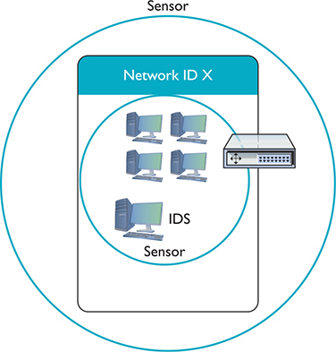
Figure 11-16 Diagram of network-based IDS
Different types of network traffic have detectable patterns, called signatures. Anti-malicious software (anti-malware) developers create definition files—collections of these signatures—for known malware. We’ll see a lot more of this in Chapter 19, but for now note that many advanced networking devices can detect and filter traffic based on signatures.
A host-based IDS (HIDS) is software running on individual systems that monitors for events such as system file modification or registry changes (Figure 11-17). More expensive IDSs do all this and can provide a single reporting source—very handy when one person is in charge of anything that goes on throughout a network.
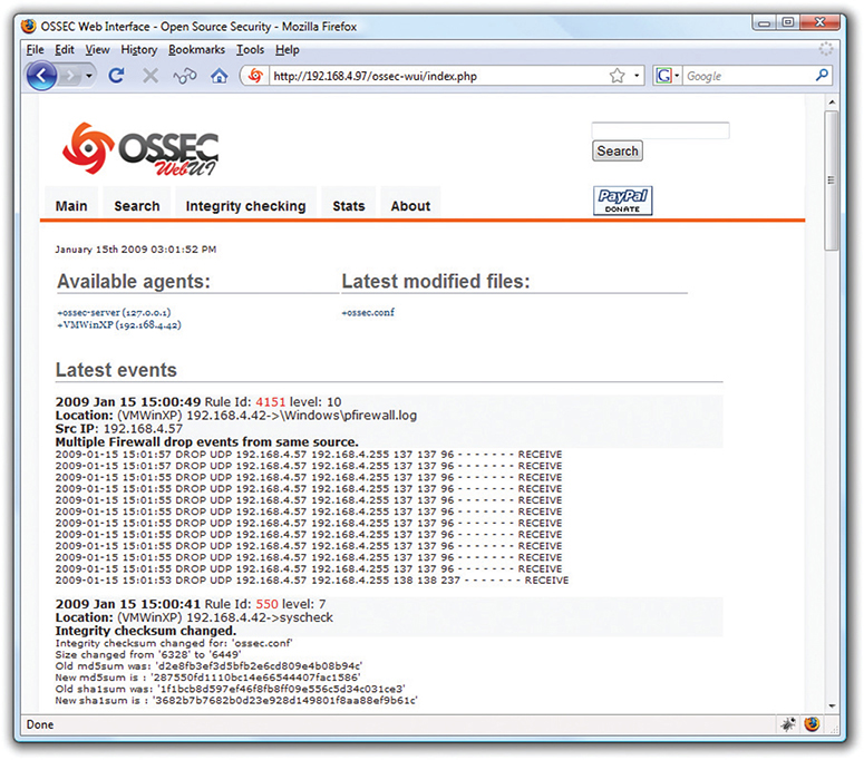
Figure 11-17 OSSEC HIDS
An intrusion prevention system (IPS) is very similar to an IDS, but an IPS sits directly in the flow of network traffic. This active monitoring has a trio of consequences. First, an IPS can stop an attack while it is happening. No need to request help from any other devices. Second, the network bandwidth and latency take a hit. Third, if the IPS goes down, the link might go down too.
Depending on what IPS product you choose, an IPS can block incoming packets on-the-fly based on IP address, port number, or application type. An IPS might go even further, literally fixing certain packets on-the-fly. A host-based intrusion prevention system (HIPS) is located on a host. As you might suspect, you can roll out an IPS on a network and it gets a new name: a network-based intrusion prevention system (NIPS).
Port Mirroring
Many managed switches have the capability to copy data from any or all physical ports on a switch to a single physical port. This is called port mirroring. It’s as though you make a customized, fully configurable promiscuous port. Port mirroring is incredibly useful for any type of situation where an administrator needs to inspect packets coming to or from certain computers.
There are two forms of port mirroring: local and remote. Local port mirroring copies data from one or more ports on a single switch to a specific port on that switch. To monitor this data, you have to plug directly into the switch with ports being monitored. Remote port mirroring enables you to access data copied from one or more specific ports on a switch without plugging directly into that switch.
EXAM TIP Port mirroring isn’t the only way to duplicate network traffic for monitoring and troubleshooting. You can also use a standalone network tap. (Some sources use TAP as an acronym for Traffic Access Port or Test Access Port.) These multi-port hardware devices literally copy 100% of the bits that they see—even errors—and send them out separate ports for monitoring. You’ll see them in scenarios that require non-obtrusive data collection.
Some advantages of a tap over a mirrored port are that the tap will perform better under high load and won’t require you to give up scarce switch ports. Plus, they’re invisible to detection, because they have no MAC address or IP address.
Proxy Serving
A proxy server sits in between clients and external servers, essentially pocketing the requests from the clients for server resources and making those requests itself. The client computers never touch the outside servers and thus stay protected from any unwanted activity. A proxy server usually does something to those requests as well. Let’s see how proxy servers work using HTTP, one of the oldest uses of proxy servers.
Since proxy serving works by redirecting client requests to a proxy server, you first must tell the Web client not to use the usual DNS resolution to determine the Web server and instead to use a proxy. Every Web client comes with a program that enables you to set the IP address of the proxy server, as shown in the example in Figure 11-18.
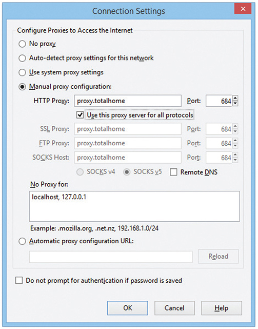
Figure 11-18 Setting a proxy server in Mozilla Firefox
Once the proxy server is configured, HTTP requests move from the client directly to the proxy server. Built into every HTTP request is the URL of the target Web server, so the Web proxy knows where to get the requested data once it gets the request. In the simplest format, the proxy server simply forwards the requests using its own IP address and then forwards the returning packets to the client (Figure 11-19).
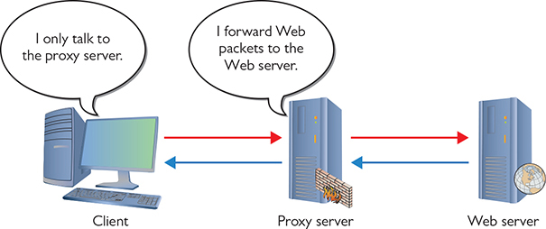
Figure 11-19 Web proxy at work
This simple version of using a proxy server prevents the Web server from knowing where the client is located—a handy trick for those who wish to keep people from knowing where they are coming from, assuming you can find a public proxy server that accepts your HTTP requests (there are plenty!). There are many other good reasons to use a proxy server. One big benefit is caching. A proxy server keeps a copy of the served resource, giving clients a much faster response.
A forward proxy server acts on behalf of clients, getting information from various sources and handing that info to the clients. The sources (servers) don’t know about the clients, only the proxy server.
NOTE If a proxy server caches a Web page, how does it know if the cache accurately reflects the real page? What if the real Web page was updated? In this case, a good proxy server uses querying tools to check the real Web page to update the cache. The benefit of a caching proxy is that content can be retrieved without contacting sites over WAN links.
A reverse proxy server, in contrast, acts on behalf of its servers. Clients contact the reverse proxy server, which gathers information from its associated server(s) and hands that information to the clients. The clients don’t know about the servers behind the scenes. The reverse proxy server is the only machine with which they interact.
A proxy server might inspect the contents of the resource, looking for inappropriate content, viruses/malware, or just about anything else the creators of the proxy might desire it to identify.
HTTP proxy servers are the most common type of proxy server, but any TCP application can take advantage of proxy servers. Numerous proxy serving programs are available, such as Squid, shown in Figure 11-20. Proxy serving takes some substantial processing, so many vendors sell proxy servers in an integrated hardware solution, such as Broadcom’s Symantec Secure Web Gateway Appliance.
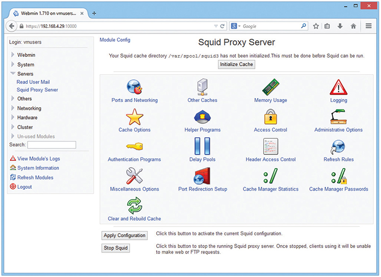
Figure 11-20 Squid Proxy Server software
AAA
Authentication, Authorization, and Accounting (AAA—pronounce it “triple A”), as you’ll recall from Chapter 10, are vitally important for security on switches to support port authentication. Port authentication gives us a way to protect our network from unwanted people trying to access the network. Let’s say that someone wants to bypass network security by bringing in a laptop and plugging the Ethernet connection straight into a switch port, or using that same laptop to connect wirelessly into one of the network wireless access points (WAPs). To prevent these types of intrusions, we use intelligent switches that support AAA.
When someone attempts a connection, he or she must have something at the point of connection to authenticate, and that’s where advanced networking devices come into play. Many switches, and almost every WAP, come with feature sets to support port authentication. My routers support RADIUS and 802.1X port authentication.
Configuring a switch for AAA is arguably one of the most complex configuration jobs a network tech may ever face. Before you get anywhere near the switch, you’ll need to make a number of decisions, such as the version of AAA you want to use (RADIUS or TACACS+), the type of 802.1X authentication methods you will use (passwords, certificates, retina scanners), deciding on and setting up the authentication database system, and opening up security policies to make sure it all works. This list is long, to say the least.
Once your AAA infrastructure is set up, you then configure a AAA-capable switch to support one or more methods of authentication. This is complicated too! There are ten flavors and “subflavors” of authentication supported by Cisco, for example, ranging from simple passwords to a local database to a RADIUS server and a TACACS+ server.
One of the really cool things about switch- and router-level authentication is the ability to fall back or fail over to a “next method” of authentication. You can configure as many fallback methods as you like, as long as the method is supported by the switch you configure. The system attempts to authenticate using the first method in a list. If that first method isn’t available (for instance, if the RADIUS server is down), it reverts to the second method in the list, and so forth.
Try This!
Chapter Review
Questions
1. A static VLAN assigns VLANs to _______________.
A. IP addresses
B. MAC addresses
C. ports
D. trunks
2. Which of the following is the trunking protocol used in today’s VLANs?
A. 802.1Q
B. 802.1X
C. 802.1t
D. 802.1z
3. Eduardo accesses a managed switch from his desktop computer on the far side of the campus. What type of access management enables this connection?
A. In-band management
B. LAN-band management
C. Out-of-band management
D. WAN-band management
4. When the network is very busy, VoIP calls start to sound badly clipped. What solution might improve the quality of the VoIP calls?
A. 802.1z
B. Traffic shaping
C. DNS
D. Content switching
5. What are the benefits of caching on a Web proxy? (Select two.)
A. Response time
B. Virus detection
C. Tracking
D. Authentication
6. 802.1X is a great example of _______________.
A. encryption
B. content switching
C. port-based authentication
D. VLAN trunking
7. Rashan’s company has multiple servers from which remote users download files. What should Rashan implement on his servers to make them appear as a single server so that they receive similar amounts of requests?
A. Load balancing
B. Port authentication
C. Port mirroring
D. Trunking
8. Which of the following statements best applies to an IDS?
A. An IDS inspects a copy of all traffic in a network and can respond to detected intrusions with actions.
B. An IDS inspects all traffic as it enters a network and can respond to detected intrusions with actions.
C. An IDS inspects a copy of all traffic in a network and reports intrusions.
D. An IDS inspects all traffic as it enters a network and reports intrusions.
9. Which IEEE protocol enables port bonding?
A. 802.1Q
B. LACP
C. PAgP
D. ZACP
10. Allison wants to add a layer of protection to her network. She wants to actively monitor all network traffic and act immediately to stop any attacks. What should she install?
A. Firewall
B. IDS
C. IPS
D. NIDS
Answers
1. C. Static VLANs assign VLANs to physical ports.
2. A. The 802.1Q standard is almost universal for VLAN trunking.
3. A. In-band management enables access over a LAN to a managed switch.
4. B. Traffic shaping will provide extra bandwidth to the VoIP applications, improving sound quality.
5. A and B. Cached Web pages can be sent to clients quickly. The contents can also be checked for viruses.
6. C. 802.1X is port-based authentication.
7. A. Load balancing spreads client requests evenly across all the servers.
8. C. An IDS inspects a copy of all traffic in a network and reports intrusions.
9. B. The IEEE Link Aggregation Control Protocol (LACP) enables port bonding. (The Cisco-proprietary Port Aggregation Protocol—PAgP—accomplishes this as well.)
10. C. An intrusion protection system (IPS) sits squarely in the flow of traffic monitoring the network, and can act immediately to stop any attacks.