
9.1 Our Concerns in Code Generation
While designing a code generator, we are concerned about the following areas which form a framework in which the code generator will have to perform.
9.1.1 Input Intermediate Representation (IR)
The main inputs to the code generator are the IR from the semantic phase and contents of the Symbol Table. By the time the code generator accesses it, the Symbol Table has stored the type information for each variable and expression, worked out by the type-checking portion of the semantic phase.
There are several possible IRs, which we have already discussed in Chapter 5. The most useful are Reverse Polish Notation (RPN), 4-tuple (three-address) code (we call it a code-matrix) and Abstract Syntax Tree (AST).
9.1.2 Nature of Target Language
The instruction set of the target language is the most significant factor which has influence over the effort required to generate a “good” target program. There are two kinds of processor architecture from the instruction set viewpoint – Complex Instruction Set Computer (CISC) and Reduced Instruction Set Computer (RISC).
CISC is characterized by comparatively few CPU registers, some of them may be designated for special purpose, generally one- or two-address instructions, a large variety of memory addressing modes, variable length instructions (giving high code packing density) and partial or non-orthogonal instructions.
RISC is characterized by a large number of CPU registers, generally three-address instructions, only a few addressing modes, fixed length instructions and almost orthogonal instructions.
By orthogonality of instructions we mean that most of the instructions such as Load, Store, Move, Add, Sub, Comp, etc. will accept any of the registers and any data size or type with the same semantics. A highly orthogonal instruction set will allow easier target code optimization (see Fig. 9.2).
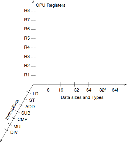
Fig. 9.2 Three “dimensions” of orthogonality of instruction set of a processor. If this 3-D cube is filled densely with points, the processor has more orthogonal instruction set
The instruction set may be designed for general register to register operation or it can be stack-based operations. Some years back stack-based architecture was quite popular and recently it is again gaining favour due to possibility of better and easier portability of the machine level language programs.
Though generating an absolute machine language program as a target seems attractive, as it can directly be loaded in the memory, without any further processing, this is rarely done, except possibly in the case of small embedded systems. Generally, it is preferred to generate object modules or files and later link them together in the form of the final executable. This is a very flexible arrangement and it also leads to code reuse.
If we generate an assembly language output – possibly in a simplified assembly language – and use the system assembler to do the assembly after the compilation, we get several advantages. First, the final address assignment to the variables can be done by the assembler and the code generator phase is relieved of that responsibility; second, the macro facility of the assembler can be used to define the target code patterns for specific IR patterns. This second aspect even goes further, for CPU differing slightly in their architecture can share all of the compilers including the code generator and just by changing the pattern macros library we can get the target code for different CPU. However, it is true that some possibilities of the machine-dependent optimization will be lost in that scheme.
9.1.3 Selection of Alternatives from Instruction Set
If the IR is low level and is nearer to the target language and target machine architecture, then it is rather simple to generate efficient target code. For example, if IR is RPN and the target machine is also a stack-based machine, then it is simple to generate the target code. On the other hand, with IR being RPN and the target machine a CISC with general-purpose registers, it requires more effort to define the mapping from IR to the target code.
We have already commented on the orthogonality of the instruction set of the target processor. There is thinking among some schools of design that the computation with floating point numbers should be executed by load and store from the same general-purpose registers as the integers and the instruction to do floating point ADD, SUB, etc. should have exactly same semantics as those for the integers. There is another group of schools which differ on this aspect due to the following reasons.
Floating point numbers are not reals as understood in mathematics. Many properties (e.g. arithmetic laws) that reals have and that one expects all kinds of numbers do not hold for floating point numbers. For example, within a computer program, it is not proper to compare two floating point variables for equality of values. Also, the way in which floating point numbers are used in a typical application is quite different from the way integers are used. Floating point numbers are used in numerical computation limited to ADD, SUB, MUL, DIV and various numerical functions like trigonometric, logarithms, exponentiation, special functions, vectors and matrix operations, etc. Code Generation for all such computations will benefit from stack-based computation regime, as the problem of CPU register allocation (see Section 9.8.1) is resolved.
We can conclude like this: if the size of the general registers is made such that it can easily contain the floating point representation on the platform and instructions are provided for movement of floating point numbers from general-purpose registers to the floating point computation stack and vice-versa, then it can be considered an acceptable enough orthogonal design of the instruction set.
We should remember that the instruction set for each CPU type is designed with certain code idioms, i.e. sequence of instructions to represent some computation patterns occurring very frequently in mind. For example, in x86 series machines, a function just on entry is expected to execute the following two instructions to set up the stack-frame:
pushl %ebp
movl  %esp, %ebp
With awareness of such idioms and ignoring the execution time taken of each instruction, it is quite easy to select the instructions from the instruction set of the target processor, for each of the possible 4-tuple instruction in the IR. Let us see where does this lead us to. Consider a small program segment given below:
a = 3
b = 5
c = 7
d = a * (b + c)
A naïve semantic phase generated the following 4-tuple code (matrix):
1:   LD    3    T1    --
2:   =    T1     a    --
3:   LD    5    T2    --
4:   =    T2     b    --
5:   LD    7    T3    --
6:   =    T3     c    --
7:   LD    a    T4    --   // redundant, a is already in T1
8:   LD    b    T5    --   // redundant, b is already in T2
9:   LD    c    T6    --   // redundant, c is already in T3
10:  ADD  T5    T6    T7
11:  MUL  T4    T7    T8
12:  =    T8     d     --  // redundant, put d in (11)
The Tn are temporaries assigned by the semantic phase, without worrying about where they will be in the actual executing program. Each of the original statement has resulted in a small, stylized, sequence of 4-tuples. At least 4 rows in the 4-tuple IR output can be removed as they are redundant.
Let us remove all the redundancies from the IR:
1:   =      3     a    --
2:   =      5     b    --
3:   =      7     c    --
4:   ADD    b     c    T1
5:   MUL    a    T1     d
What we have done is to optimize the IR, the process is termed machine independent optimization and is the subject matter of Chapter 10. Now suppose we “code generate” this IR into our target code, the language for which we have selected, for this example, the assembly language of x86. We decide to use an idiom
movl  p, %eax
addl  q, %eax
movl  %eax, r
for a three-argument operation r = p + q, which can be directly expressed as a 4-tuple ADD p q r. We can use any other binary operator in place of ADD. Note that the assignment is built into the 4-tuple notation, but stand alone assignment r = p can use a simpler idiom
movl  p, %eax
movl  %eax, r
Now we set about the code generation for the given IR, looking at each of the five rows of the optimized IR and inserting appropriate operands in the idiom for each of the 4-tuples.
movl   $3, %eax
movl   %eax, a
movl   $5, %eax
movl   %eax, b
movl   $7, %eax
movl   %eax, c
movl   b, %eax
addl   c, %eax
movl   %eax, T1
movl   a, %eax
imull  T1, %eax
movl   %eax, d
There are several ways in which the code generated above can be made more efficient. We can select a better instruction sequence for assigning an integer constant, instead of the two-instruction sequence we used blindly. That better idiom, indicated by closer study of the instruction set, is movl $3, a. This will remove 3 instructions from the above target code.
We could select for the 4-tuple ADD p q r, the idiom
movl  p, r
addl  q, r
again by closer scrutiny of the instruction set. Then the generated code could be
movl   $3,    a
movl   $5,    b
movl   $7,    c
movl   b,     T1
addl   c,     T1
movl   T1,    %eax
imull  a,     %eax      // due to nature of imull instruction
We could have used CPU register eax, in place of T1, and reduced one more instruction. That would be a small example of machine-dependent optimization.
Operations like i = i + 1 is very frequent in normal programs, and most of the CPUs provide incr instruction for efficiently coding them. If the IR is made to contain a unary operator INC instead of i = i + 1, the code generation is straightforward.
9.1.4 Allocation of CPU Registers
Even the very simple examples shown above should have told you that decision about which value is to be held in which register can become quite tricky. Apart from limitations on special-purpose registers, proper allocation of registers can make the code more efficient. You should remember that registers are at the top in memory hierarchy in a computer; they are the fastest storage units accessible to the processing units and they are always in the short supply. Also, for most of the processors, the instructions operating on registers are shorter and faster (because they are shorter and deal with fast registers).
The allocation of registers has to take into account not only the current 4-tuple, but what further operations take place on the variables involved in the next few 4-tuples. Let us take an example. The following 4-tuple
ADD a b t
would be translated to
movl a, t
addl b, t
If the next 4-tuple is
MUL t c t
The generated code cannot be
imull c, t
as the imull instruction expects Reg/Mem/Imm as the first (src) operand and Reg as the second (dst) operand. This means that the generated instruction should be something like
imull c, %reg
However, then we better change our decision about the first 4-tuple and generate code for the two 4-tuple as:
movl   a, %eax
addl   b, %eax
imull  c, %eax
movl   %eax, t
Note that the multiplication instruction always leaves the result in the coupled registers edx:eax.
Further, suppose the next 4-tuple is
DIV t d t
that is t = t/d. We shall have to use the idiv instruction, which expects the dividend in edx:eax and divisor as an operand, which can be a register or memory. The generated code now becomes
movl   a, %eax
addl   b, %eax
imull  c, %eax
movl   %eax, %edx
idiv   d
movl   %edx, t
9.1.5 Order of Evaluation Sequence
In a long numerical expression, we may find that some particular execution order results in a more efficient target code, at least in terms of register usage. Most of the modern CPUs are pipelined, i.e. execute several instructions in parallel. This opens up a possibility of considering the evaluation order in depth, on the one hand, and the correct computation must be achieved, on the other hand; reordering of instructions will result in faster code. We postpone the discussion of this last aspect of code generation till Section 9.8.2.