
CHAPTER 16
Contributions
This chapter features contributions to this book by some of the most respected individuals in mastering and related fields today. Each contributor provides a unique and valuable perspective on their topic.
Robin Schmidt is the owner of 24-96 Mastering in Karlsruhe, Germany. His work has been popular throughout Europe and the United States, including releases with artists such as Two Door Cinema Club, OMD, and The Black Keys. His work on Louis Spohr’s “String Sextet” was nominated for a Grammy Award for Best Surround Album in 2011. His work also includes Jake Bugg’s self-titled album (number 1 on the U.K. charts in 2012), Ben Howard’s Mercury Prize–nominated platinum-selling debut album “Every Kingdom,” and The Coral’s “Butterfly House” (U.K. album of the year in 2010).
Robin Schmidt helps us to understand how he chooses equipment. He uses this topic as a base to explain part of his mastering philosophy.
On Analog Multiband Compression and Audio Gear
Robin Schmidt, Mastering Engineer
Owner of 24-96 Mastering, Karlsruhe, Germany
I bought an analog multiband compressor a few years ago on the recommendation of several mastering engineer friends. The package was very appealing: three bands of smooth opto compression, followed by a tube stage that, depending on how hard it’s driven, was able to go from a very clean sound to delivering quite a bit of attitude.
After trying a few different sets of tubes, I settled for a combination that sounded clean and controlled until pushed hard, with low noise and microphonics.
I started using the unit on actual masters in the following weeks and liked its compression behavior and sound signature. But I found that even with great tubes and a well-calibrated machine, stereo levels fluctuated more than ideal. The reason for this is simple: In any analog compressor, there are parts that don’t behave exactly linearly and have manufacturing tolerances. Opto cells, used for gain reduction, for example, never exactly match, and level controls (variable pots) are typically manufactured to allow a several-percent deviation.
With a normal stereo compressor, this means that the left/right balance may need adjustment after processing because the left and right level controls may be tracking slightly differently at any given setting. One channel may need to be turned up or down from indicated knob positions to match the other in real audio level, and a good mastering engineer will routinely check that left/right tracking is spot on.
However, with an analog multiband compressor, this gets more complicated. Consider that you now have potential level deviation between left and right channels in every frequency band. So, with any given setting, the bass frequencies may lean half a decibel to the left, the mids 1 dB to the right, and the highs may be exactly center. This isn’t much of a problem in a recording situation, where amounts less than 1 dB are rarely that critical, but in mastering, these image shifts can become audible.
Luckily, the manufacturer was well aware of the requirements of mastering engineers and has a mastering version of the unit available. It employs resistor-network switches instead of pots and, in that way, gets rid of most of the stereo tracking deviation. So the normal unit was sold and a mastering version acquired instead. This one had much better stereo tracking, and the sound was a bit tighter to my ears as well. Perfect.
So there it was, the ideal analog opto/tube multiband compressor with the perfect tube combo, tightly calibrated. It sounded great, behaved well, and was a joy to use.
Still, over the months that followed, I found myself using it less and less.
The unit sounded great for imparting some tube tone or a slight overall sweetening, but when that was all that was needed, I tended to use other, simpler options, such as a vari-mu compressor or even just a set of transformers in the signal chain.
Instead, most of the time when I reached for multiband compression, I did so with specific tasks in mind—to control an uneven low end, to tame a screechy hi-hat, to soften sharp high mids in a vocal, etc.
After I had just gotten my analog multiband compressor, this was the default option for these tasks. But over time I found that more and more often I returned to solve such specific issues in the digital domain with multiband compression or dynamic equalizer plug-ins. While the analog unit sounded great, it lacked the flexibility, the ability to automate, and the ability to quickly compare different settings/approaches.
Analog multiband compression lacked the control that was so useful in dealing with these kinds of very specific, narrow, and inconsistent mix issues.
Sure, the unit sounded great. But what does that matter when you can’t actually get down to the exact problem in the mix? Or when you can’t apply it exactly in the ideal amount on only the relevant part? Or when the inability to compare different settings discourages you from trying different approaches to find the best way to solve the issue?
With a superb-sounding analog multiband compressor in the rack, I usually ended up choosing bog standard plug-in multiband compression instead so consistently so that in the end I sold the unit so that someone else could put it to better use.
This story, to me, illustrates a common quality that’s often overlooked or not sufficiently mentioned when we talk about audio gear: that the most magnificent-sounding piece of gear is no good when you can’t apply it exactly as you need to.
We often rave about the qualities, the sound color, or saturation characteristics of a Neve, Fairchild, Pultec, or other mythical box in absolute terms, as if they were black boxes, universal “bettermakers.” But we rarely talk about how applicable a unit is, how much control the unit offers, what we can and can’t do with it, and whether it encourages or discourages us from tweaking until it’s just right.
I think it serves us well to acknowledge that in practice, when we’re talking about manipulating audio, control is sound. The two are inseparable. Too little—or too much—control, and whatever sonic mojo a box might hold won’t be used to its potential and might, in fact, limit the potential of the tweaking user as well.
The right amount of control is, of course, a very personal thing. A piece of gear that hinders one user’s workflow might be perfect for another user. I know this to be true in the case of my analog multiband compressor. A mastering engineer friend of mine told me that he had to have his unit serviced and was dreading the downtime while it was out of the studio because the unit held such a vital place in his chain. For his workflow, the function he used the unit for, his taste, the unit had just the right amount of control.
And tastes don’t just vary among different people, but also for one person, over time. Very often you’ll find mastering engineers talking not about how they’re currently gearing up, but rather about how they’re gearing down, removing the “clutter” in their signal chains and workflow, essentially reducing the amount of control they have and feel that they are doing a better job because of it, because they find that they can better concentrate on the really relevant aspects of their work. A potentially cleaner signal path comes as an added bonus.
We all love our gear and have a very personal relationship with it. We select and collect it, invest in it, take pride in it, and love talking about it. Audio gear has heritage, it helps to create a shared studio culture, and it enriches our daily experience. It’s a beautiful thing. But every now and then it’s worth reminding ourselves that these pieces of gear are—above all else—tools, and as such, on the whole, they have to work for us rather than make us work for them.
Scott Hull is the owner and chief engineer of the iconic Masterdisk in Manhattan. Masterdisk contains several mastering studio suites and is one of the longest established mastering studios in the world today. Scott Hull’s career began as an assistant for the legendary Bob Ludwig, who mastered classic albums of AC/DC, Rush, Jimi Hendrix, Madonna, Eric Clapton, David Bowie, Rolling Stones, Radiohead, and Nirvana, to name a short few. Hull’s own career has developed to be one of the most noted success stories in professional audio mastering. He personally has over 1,600 album credits, including influential albums by Dave Matthews, Garbage, KISS, Miles Davis, Herbie Hancock, Bob Dylan, The Allman Brothers, Sting, Donald Fagan, and Wynton Marsalis, among many others. He mastered two Grammy-winning albums of the year, John Mayer’s “Room for Squares” and Steely Dan’s “Two Against Nature.”
In this contribution, Scott Hull describes his view of full-range monitoring. One might notice that in every mastering suite of Masterdisk, high-quality full-range monitoring is used. Scott explains why he believes this to be a vital part of professional audio mastering.
The Case for Full-Range Monitoring
Scott Hull, Senior Mastering Engineer
Owner of Masterdisk Mastering Studios, New York, NY
Music is taken into the body and interpreted by all our senses. While our ears get all the credit, I’ll bet that most of you have observed that music feels different in different environments. The vibration of the floor, the air pressure or thud of the bass in your chest, the spatial information that your eyes collect, the phantom images created by your brain, and the simultaneous reaction of others influence how you react to music. These opinions are based on what environment you are in, not only on what you hear. Many scientists have created elaborate trials to learn about human hearing, but one thing that I contend is true from my experience is that you cannot completely isolate your ears or your perception from other environmental factors.
One obvious alternative for monitoring music is to place the transducers right next to your eardrums so that you only hear the electrically produced sound and nothing from your environment. That may be valid, but only if you began listening to music this way from birth and never heard music played in a room where you experienced the complete picture. When we listen to headphones, our brain is trying to connect what it hears with what we have heard before. This pattern-matching phenomenon is well documented in our other senses: vision, taste, smell, touch. For instance, if something tastes like something we remember, then that is what it is. Many other observations are similar.
I feel that to truly react in an emotional way, you need to experience the overall impact from the music. Small speakers or even midfield-sized monitors can give you a very technical observation. But the impact of the entire spectrum, I think, is everything. For me, this emotional reaction is not as profound when played through smaller speakers.
Here are a few technical reasons why small monitors are less than ideal. Subbass frequencies below 50 Hz are very difficult to reproduce from a near field. To make these speakers seem like they have lower fundamental frequency response, the manufactures put ports and passive radiators on the speakers. Some of these work great at producing a very pleasant-sounding experience, but almost all of them do this at the expense of flat frequency response. The specs on these speakers claim flat response, but I find that only tells part of the story.
When mastering, we are constantly testing different settings. A-B-ing. If I think a piece of music could be improved with a little more bottom end, I will experiment with a decibel or so of EQ at several different frequencies. Often my instinct (guess) is right-on; other times it’s a nearby frequency. But what I find very interesting is that on small speakers 1 dB of bottom EQ—for instance, around 70 Hz—might be completely inaudible. In other words, if I boost 1 db at 70 Hz with an equalizer, I cannot perceive the change—it sounds the same. And this usually leads me to over-EQing—adding more EQ to achieve the desired result. But when I’m curious and hunt around, I might find that on these speakers 1 dB at 62 Hz is completely audible. The dilemma is which is right? My presumption is that when using a ported enclosure to produce more dramatic low-end response, the resonant frequency of the port plays a role in the listening experience. While the speaker sounds like it has enough low-frequency energy in general, it may not be an accurate reference. You can get used to the sound, but if you cannot discriminate the difference, then it doesn’t make a good reference monitor. The relative success of small speakers depends on the program material. In fact, the key of the song has a bearing on this. If the fundamental frequency of the tonic (root) pitch in the bass lines up with the port resonance, then it may appear to have way too much bass, causing you to reduce the bass energy in your music—but only on those notes (frequencies) closely related to the fundamental frequency.
What Is That?
Nearly every single day in my mastering room I am working on a record that I haven’t heard ever before. It’s a new experience each day. I love that about mastering. But one thing that is consistent is when producers and mix engineers attend my mastering sessions, they almost always say to me, “What is that?” They have just heard something new in their mixes that they never heard before. This isn’t in itself a problem, but the reason they bring this up is because it’s usually some sort of subtle defect that doesn’t sound subtle at all in my room. This magnifying-glass approach is essential in mastering, and not only in the high frequencies. Without that clarity and full-range response, along with amplifiers that have a nearly infinite slew rate and very low noise floor, those subtle defects are masked. Even the little fan that keeps your computer cool produces enough background noise to make finding small clicks in the music almost impossible.
But What About the Consumer?
We all are very aware that the music consumer will listen on ear buds and laptop speakers under the keyboard and all sorts of other environments that are very far from ideal. So why go to such lengths to create an ultraquiet listening space, have high-resolution converters, enormous amplifiers, and speakers that are actually as tall as I am? The answer is simple: I need to be able to hear and feel everything, and this is the environment I am intimately familiar with. These speakers are my ears.
What Are My Goals in Monitoring?
I must be able to discriminate EQ and level changes down to the tenth of a decibel. For real—that is what I do on a daily basis. If your textbook tells you that you can only hear a change of ±3 dB, you are reading from a completely outdated book. When making changes in EQ in these tiny increments, the observation is almost always communicated as a feeling or an impression. “It feels like there is a bit more edge or air or presence or body or warmth.” But collectively these supersubtle changes are what give my mastering dimension and emotion beyond basic sound quality and dynamics. If you cannot discern these minute differences, what are you really hearing? This is heavy stuff. You only get to this place by making mastering your life’s work. Mix engineers and producers move from room to room and do a tremendously great job of adjusting to their environment. Mastering engineers, however, try to control our environment and use a singular monitoring approach. This way I know what I am hearing, and I can adjust for it immediately. It’s been said that a (wo)man with two watches never really knows what time it is. I have to say that I feel exactly that same way about my monitoring system. One set of ears, one set of speakers—and amps—and cables—and one room.
Music is emotion.
Jaakko Viitalähde is a mastering engineer, electronics enthusiast, and founder of Virtalähde Mastering in Kuhmoinen, Finland. He personally custom-built and designed most of his studio facility and equipment down to the monitors, equalizers, and console. His remarkable experience and range of skill afford him a deep understanding of mastering processing and equipment.
In this section Jaakko Viitalähde explains his well-developed views about optimizing an analog signal chain for mastering.
Connection and Calibration of an Analog Mastering Chain
Jaakko Viitalähde, Owner and Mastering Engineer
Virtalähde Mastering, Kuhmoinen, Finland
Prologue
A mastering room installation seems like a relatively straightforward job on first look. Usually, there are only a few well-selected tools to connect together, and the required flexibility in routing is much less compared with tracking or mixing rooms. Yet, despite the apparent simplicity of the installation, great care must be taken in bringing it all together. The aim of any mastering room is to be capable of doing short, clean signal transfers and to bring out the best in the source material in the most intuitive way possible for the engineer. I will provide some food for thought and discuss ways to improve workflow.
Building Up a Chain
A mastering chain is never just a random collection of tools thrown together. There is a reason they are built like they are, and it all comes down to the engineer’s matured personal preferences and ways of working. While maximum flexibility and freedom in patching might at first seem like the perfect idea, there is a very good chance that patterns will be found in workflow after the equipment has been around long enough and a fair amount of work has been done with it. By being aware of your own working methods and by actively challenging yourself, any mastering chain can be effectively streamlined.
The minimum requirement for any piece of equipment used in mastering is to sound good when set flat. Sound, or tone, is a highly subjective topic, but for a sonically transparent tool, the tone of a unit with no actual processing applied should be the same as the source or better with any source material. If the tone is “almost there,” it makes no sense to keep such tools in the chain unless used only occasionally and there is no substitute for what the actual processing does. Tone tends to cumulate and eventually may lead to compensating for the slightly inferior tone of the chain with unnecessary processing.
Having tools with a tone that works with only some incoming material is perfectly fine. The core of the mastering chain should, however, work with just about anything that needs processing. Transparency goes a long way with a core chain that is both sonically transparent and a little bit better sounding with any incoming material.
A/B comparisons performed with the digital audio workstation (DAW) are an effective method for evaluating tone in an objective way. Bypassing a unit can tell you something, but judgment is still affected by small changes in level and even by differences caused from interaction between units. Some outputs sound different when driving various inputs, so a unit bypassed in between other units does not necessarily provide a clear perception of how the unit sounds at a specific spot in the chain. Properly implemented, A/B comparisons remove every such variable and provide the freedom for trying out different kinds of combinations without being misled.
By capturing the sound of the chain and its various parts or combinations back into the DAW, the carefully level-matched files can be blindly compared to the source material. The results can be brutal, and there is a good chance of finding out that the sound of the original files is preferred. It is true that applying actual processing changes things, but even with the desired processing used, the same basic tone will always be there. If the source material needs some EQ, is it better to have a sound that is “almost there” with the additional EQ or one that sounds the same or better plus the applied EQ? At the last critical stage of mastering, every little detail counts.
Good-sounding individual tools are only the beginning, and it takes a lot of time and effort to build a balanced-sounding mastering chain. A large part of this is finding tools that work well together, making the combination greater than the sum of its parts alone. As discussed previously, the core of any mastering chain should be fairly simple, transparent, and flexible enough for most of the daily workload, and it is the perfect place to start. When you have a chain that sounds good on just about everything, adding tools with a tone that fits only some material is much easier.
The overall patching order is something that evolves over time. While some consoles do allow for total freedom in patching, parts of the chain often tend to end up in a fixed order because they simply sound better that way. This depends on how the inputs and outputs are constructed, and the only way to find the best arrangement is to carefully listen to how various configurations sound. Because the patching order is affected both by personal preferences and by the fact that one combination sounds better than the other, experimentation is required for finding a good balance.
Patching Methods
The simplest way for patching is daisy-chaining (also called point-to-point wiring). Patching a chain from one unit to another is a common method and can be an extremely pure way for building up the signal path. Such a method works very well when the number of tools is fairly limited and the patch order rarely or never changes. The interconnections can be kept very short, and the number of mechanical contacts on the signal path is kept to a minimum. Obviously, as the amount of equipment grows, the overall chain gets rather complex to handle, and the signal travels through a lot of contacts, even when bypassed.
A fixed patch relies entirely on the quality of the individual local bypasses. Not all of them may be true bypasses, which by standard removes the circuit completely from the signal path. This is the electrical equivalent of connecting the XLRs back to back. There are also bypasses that may keep the input active at all times and just switch between the input and output, keeping an extra load on the preceding amplification stage at all times. Another possible bypass is that which keeps some circuitry in the signal path, such as the I/O amplifiers. Knowing how the bypasses are built is essential when building a point-to-point patched mastering chain.
For more flexibility in routing, mastering consoles are often used. They come in all shapes and sizes, passive and active, and while the small details may differ quite radically, at their core, most of them offer some type of inserting system. The number of available inserts may vary from three to eight or so. The less available inserts there are, the more likely the user will be daisy-chaining several pieces of equipment together inside an insert, and with more inserts, each insert will serve as a clean, short way for bypassing each tool individually. Most consoles have passive inserts, which should, in theory, be as transparent as possible. This also makes the installation much more dependent on how the individual tools interact with each other. If the inserts are actively buffered, this dependency is broken, but buffering does add a few extra stages of potentially unnecessary amplification to the chain.
With a wider selection of tools at use, a good and flexible mastering console is an elegant way for controlling it all. Many consoles offer additional features such as M/S matrixes and ways for controlling the patch order within the console. Bypasses are clean, with each located in the same place, and the signal does not have to travel through every piece in the desk if the required job at hand needs, for instance, only one EQ. However, the opposite is true for more complex patches because there is increasingly more back-and-forth cabling and extra contact points in the signal path compared with a similar fixed patch.
Patchbays are another option, but they are rarely used in mastering rooms. While a patchbay does give good flexibility in routing and can be just as good as any other patching method when properly installed, patchbays are not often necessary because mastering chains tend to be quite simple and fixed in order, even when wrapped around a mastering console.
The interconnections used should always be built from cables and connectors of good quality and be as short as possible. By clever physical placement of the equipment in the racks, the length of the interconnections can be easily customized. Arranging your tools cleverly also has an effect on your workflow. Easy access to everything and a sense of balance in the racks promote a good working mood.
Installation, Calibration, and Operating Levels
A typical mastering chain might be a mixture of both balanced and unbalanced interconnections. Some commonly used tools in mastering come with unbalanced inputs and outputs, but because the cable runs are usually short and induced noise is not typically a problem in mastering rooms, there is nothing wrong in using unbalanced interconnections. In fact, running unbalanced can in some cases sound better if the inputs and/or outputs are modified and balancing/debalancing stages are bypassed or removed, transformers in particular. Such modifications are another step in tuning a mastering chain for its best possible performance.
Inputs and outputs can be balanced both electronically and passively by using transformers. Transformers are excellent for isolation and trouble-free operation, and they can be used either balanced or unbalanced, but they are never completely transparent in tone. Transformers can be a little picky on the preceding line driver or the load after them, and there will always be low-frequency distortion and overall phase shift present to some degree. Some transformers do sound excellent, but not all of them. When using a transformer-balanced input or output in an unbalanced system, the cold pin (usually pin 3) always has to be grounded or there will be a noticeable loss in level, especially at low frequencies. If the connection to the transformer does not have its pin 3 grounded, it has to be wired to the ground (pin 1) in the interconnection cable or by modifying the I/O stage.
Electronically balanced inputs and outputs are usually quite easy to mix with unbalanced circuits. As always, pin 3 must be grounded when operating a balanced input unbalanced, or the unconnected input at pin 3 might induce noise in the circuit. Some balanced (nonfloating) outputs do not like their pin 3 grounded, and there can be 6 dB of loss in level or even damage to the output circuit. If such an output has to be connected to an unbalanced input, pin 3 needs to be left unconnected at the other end. Another solution would be to use an extra debalancing stage, which would also solve the level-drop problem.
A well-implemented grounding scheme can reduce low-level hum and buzz in any installation, and mastering rooms are no exception. A completely balanced chain is usually very tolerant of slight imperfections in grounding, but unbalanced connections could require extra care. With some equipment, problems can emerge if pin 1 is grounded directly to the circuit ground instead of the chassis ground, as described in Rane Corporation’s note, “Grounding and Shielding Audio Devices,” by Steve Macatee (www.rane.com/note151.html). This may result in hum and buzz problems. Without modifications, the only thing to try is to disconnect pin 1 from the interconnecting cable at the signal-grounded end. The referenced Rane note is an excellent resource for any installation and its potential grounding problems and is worth reading by anyone.
Usually, impedance Z is not a thing to think of when connecting modern studio equipment together. The outputs are low Z and the inputs are high Z, so the output drivers have no trouble driving a high-Z input. Lowest nominal input impedances tend to be in the 2.5-kΩ ballpark, which should be plenty for most outputs to drive.
However, some transformer-balanced inputs may represent a more complex load that demands more from the preceding output stage to sound the best. This explains in part the differences heard in various combinations of equipment, and the only way to find what sounds best is to test all possible combinations that make any sense at all.
Pre-1960s equipment is relatively rarely used in mastering, but when such equipment is connected to a modern line-level system, it is mandatory to thoroughly check whether it is designed to work in a 600-Ω installation. This means that the inputs are of low impedance and need a strong driver stage before them and also that the output needs to be terminated properly with a 600-V resistor if the output connects to a modern high-Z input.
One of the most important and often overlooked aspects is the operating level of the system. Any mastering chain needs to be calibrated to a chosen reference level. There are no standards to follow, but in general, low levels work well with analog equipment, and when there is enough headroom available throughout the chain, the sound will be much cleaner. There is a time and place for driving parts of the chain with higher levels for various saturation effects, but for the most part, using operating levels that are near the clipping point only does harm to the audio.
For example, an often seen reference for 0 VU (or +4 dBu) is –18 dBFS. This leaves us with only a tiny reserve of headroom because 0 dBFS sits at +22 dBu, which comes close to the clipping point of some of the generally used equipment. By choosing a dramatically lower operating level, such as –8 dBFS, +4 dBu, 0 dBFS is +12 dBu, leaving us with 10 dB of available headroom for equipment with a clipping point at the mentioned +22.5 dBu. Many line-level amplifier circuits are grossly nonlinear near the clipping point, but it only takes a few decibels of safety margin to considerably clean up a chain. Naturally, by driving the chain less hot, you are also operating closer to the noise floor, but since mastering equipment should, by standard, be of low noise, this is usually not a problem.
Closing Words
A large part of getting into the flow is having a set of tools that do not require much thinking while working. Spending a long time on one track tends to blur the judgment, which is why it is crucial to thoroughly know how your mastering chain works in its various configurations. When everything has found its place, there is no second-guessing, and the important decisions can be made quickly.
The tools of a mastering engineer truly are a balancing act. It takes time and patience to build a mastering chain, and it is as delicate as mastering work itself.
Dave Hill founded the highly respected equipment manufacturing companies Crane Song, Ltd., and Dave Hill Designs. He is one of the foremost equipment designers in the world of recording and mastering and is the subject of the documentary film Crane Song Superior Gear: The World of Dave Hill. His designs can be found in most modern professional mastering studios as well as many recording studios across the globe. He is especially known for the quality of his harmonic distortion processors, which are so renown that a version is now included in ProTools.
Dave Hill helps us to understand how harmonic distortion processing can be used to shape tonality.
Distortions and Coloring
Dave Hill, Audio Engineer and Owner of Dave Hill Designs
Equipment Designer for Crane Song, Ltd.
Introduction
Distortions come in many forms, ranging from obvious to subtle. Some are useful, whereas many simply sound bad. When distortion is used for color, it can be a powerful tool, but it must be used carefully. In precise terminology, anything that alters a sound could be called distortion. This includes such common tools as EQ and compression. Among other uses, EQ is often thought of as a correction tool, allowing us to correct for distortion and inaccuracy. Compression/limiting, when used to make things loud, creates a distortion that is not pleasing to the ear. Limiting was first designed to control infrequent peaks. When used as something to make the source louder, with almost constant limiting, it is not a good thing. The ear thinks louder is better at first listen, but a more realistic perception about this can be had by listening with carefully matched loudness levels or from extended listening. We begin to hear the unpleasant distortion this way.
Think about human hearing. Nature does not have continuous, loud sound sources. Hearing most likely developed for communication/speech and for survival. If all that is heard is high-energy sound, for which the ear did not evolve, what are the long-term consequences?
There are many cases where restricted dynamic range is needed so that the source can be heard, but the resulting sound is not ideal. There are many records that have done very well without having the life compressed and limited out of them. An example is “Dark Side of the Moon.” It has dynamics, something that is being lost in modern recordings. The trend has been to make things play louder and louder, and the result is deteriorating sound quality. Such undesirable distortions should be avoided.
Distortions as Color
Hearing is quite an odd phenomenon and is not very well understood. It turns out that distortions may not be heard as distortion. For example, when adding second harmonic distortion to a source, because it is an octave musically, it can be very hard to hear. However, it does change the character of the sound. Some people cannot hear a difference even when large amounts of second harmonic distortion are added. On a pure-tone instrument it may give a bad sound, but on a complex sound there may be an enhancement. “Euphonic” is how some high-end hi-fi enthusiasts describe the sound of their tube amplifiers that produce a significant level of second harmonic distortion.
There are many examples of color with analog gear. People may like a certain piece because it has a warm sound. Is this sound due to a nonflat response—a high-frequency (HF) or a low-frequency (LF) boost? In many cases it is frequency-response errors that we hear first, not harmonic distortion. Some people describe a certain D/A converter as having a warm sound, whereas the sound is actually the result of distortion introduced by filter problems.
Whereas the character of a piece of audio equipment could be due to a frequency-response error, harmonic distortion also could be responsible. For example, third harmonic distortion and other odd-order harmonics can produce a bright sound. It can be a desirable sound with the right input level and with lower-order harmonics. On the other hand, higher-order odd harmonics tend to be harsh-sounding. Generally, it is harmonics above the fifth that are often referred to as higher order, with the lower ones being called lower-order harmonics. When one peak limits and turns a source into a square waves, the distortion we have is in the range of high-order odd harmonic distortion, which is bright and harsh.
Magnetic tape primarily introduces third harmonic distortion, but there are distortion-level versus frequency-response considerations and system frequency-response errors—head bump, HF roll-off, and many other effects take place. On tape, the distortion level will increase with frequency owing to reduced HF headroom, although, because of the response of the playback amplifier and other factors, we do not hear the HF part of the distortion very much. Also, because usually the HF content of a recording is not large, what we hear is mostly the LF and low-midrange distortions, the time-domain errors, and the effect of low HF headroom on transients. The point is that just because we can introduce harmonic distortion as a coloring effect, it is not always good or predictable. Part of the charm of analog gear is the unpredictability, unlike the digital domain. The part of tape we like is the warming of the midrange with harmonic distortion. There is some transient reduction, but if you push tape to seriously remove transients, the high end becomes dull. Overall, a good tape machine used with typical levels will not change the sound very much.
Nonlinear
With analog gear, the mechanism that creates harmonic distortion is an error of linearity—an error of the input-to-output relationship. This nonlinear relationship varies based on the signal level and frequency. Take the idea of soft clipping—the tops and bottoms of the signal are being rounded off instead of chopped off. Because this is taking place on both the top and bottom halves of the wave shape, we are adding odd harmonic distortion. The shape of the rounding will affect the level and type of harmonics that are generated. The function taking place is symmetrical, meaning that the top and bottom of the wave shape are affected in the same way.
Analog gear will have something between a very hard clip and a soft clip depending on the circuit type. Integrated-circuit (IC) amplifiers tend toward the hard clip, whereas tube amplifiers tend toward the soft clip. One must be aware that this is very general and that each amplifier has its own characteristics.
Now if we round off only the top or bottom of a wave shape, we have asymmetrical distortion, and it will be mostly even harmonic distortion.
The shape of the nonlinearity changes the distortion. The generated distortion may or may not be heard as distortion or even heard at all. If you add frequency-response-dependent nonlinearity to this, you may have a piece of gear that could be very clean until 5 kHz and above or perhaps clean above 100 Hz.
The generated distortions on the low end could sound like a fat, warm sound, or it may make the low end more undefined sounding, mushy, although with some types of music this may be a good thing. Distortions above 5 kHz may sound like “air” or brightening, or instead it could sound edgy and bad. Different source material with various levels will be affected differently. What happens in assorted analog gear can vary widely. No two units, even of the same type, will have exactly the same character. There will be small variations.
Along with the generated harmonic distortions, there is intermodulation distortion.
This is mostly a bad thing. It is the generation of non-musically related tones into the program. If the nonlinearities are soft enough, the amount of intermodulation distortion may be so low that it is not audible.
Time Domain
Distortions in time are a bigger problem than is recognized. We often think of transients and wanting to smooth them or slow them down, and doing this can make some material more listenable. It is also thought of as something we must lessen so that the music can be louder. This takes life, “air,” and space out of music if pushed to the limit. This is perhaps the most well-known and widespread problem in the time domain.
Time-domain problems that are not so apparent to those who have never heard anything other than 44.1k recordings relates to imaging. This is known as pre- and postecho.
Pre- and postechos of the program source are added to the program when working with digital audio. It is most apparent on transients, such as guitar strums. This effect is known as the Gibbs phenomenon and is part of the physics of digital audio. The linear phase filters used in converter circuits create the pre- and postechos, disturbing the imaging. There are several techniques circuit designers can employ, such as the use of minimum-phase filters, but it is impossible to completely avoid the phenomenon. These filters, used for antialiasing, are a required part of both A/D and D/A conversion and are a major source of time-domain issues. Given the steep filter requirement of the 44.1k sample rate, it is not possible to avoid linear-phase filters without undesired side effects. The only real way to improve this is to use higher sample rates; 192k sources image much better than 44.1k sources. It turns out that processing at 192k also sounds better. There are many benefits to working at the higher sample rates, even if the end will be 44.1k or worse. If the source sounds better to start with, then the end result will be better. Processing with analog gear or other effects will not remove the time-domain errors once they are present. For this reason, the number of conversions is often kept to a minimum.
Coloring
When dealing with a recording that needs work to make it more presentable, there are the standard tools (i.e., EQ, compression, reverb effects, M/S techniques) as well as tools that change the harmonic content. These harmonic tools work by introducing analog-like errors to the digital source. If used skillfully, they can affect the sound in a positive way, making it sound less “digital.” The better processes will be a bit unpredictable because the result depends on the level and frequency content of source material, just like analog gear. One can use a tape-like emulation to fatten the lower midrange, which is not possible with an EQ. If ones adds third harmonic distortion of the correct type, the sound can become brighter and bring out detail.
If a compressor limiter is used to raise the level of a sound, it is usually best to perform the coloring first, before the dynamic range reduction. If coloring is done with something other than EQ on a source that has little dynamics left, it must be done carefully to prevent displeasing distortion.
The best results with harmonic processing are with open material with space to allow the altered harmonic structure to be heard.
Brad Blackwood is the owner of Euphonic Masters in Memphis, TN. His remarkable mastering career began at Ardent Studios in Memphis, TN, where he revived the Ardent Mastering brand. He has over 3,000 album credits, including work for artists such as Maroon 5, Black Eyed Peas, Everclear, POD, North Mississippi Allstars, and Three Days Grace. His work has received several Grammy nominations. In 2012, Blackwood won a Grammy for Best Engineered Album for his work on Alison Krauss and Union Station’s “Paper Airplane.”
Brad Blackwood shares with us his views and techniques for mid-side processing. This provides a glimpse into the ideas developed by a professional who has successfully integrated this processing into his everyday approach.
Mid-Side Processing
Brad Blackwood, Mastering Engineer and Owner
Euphonic Masters, Memphis, TN
While a vast majority of my work is done via standard stereo processing, I do use mid-side equalization quite a bit (EQ is the only processing I use in M/S mode because I’ve not heard mid-side compression that sounded right to me). I do this in the analog domain, using a custom-built analog M/S matrix along with the Crane Song Ibis EQ, which is perfectly suited for mid-side work because of its overall flexibility.
Most balancing and frequency-response issues are best addressed via stereo EQ, but there are times when I feel that mid-side EQ allows me to more transparently tweak the audio. For example, if you have a nice vocal/snare sound but the hard-panned guitars are dull, mid-side EQ can allow you to open up the guitars without affecting the vocal and snare. Likewise, if you have a mix where the vocal or snare needs to come up a touch, those elements can be enhanced via middle-channel EQ without applying unnecessary equalization to the entire mix. M/S processing also can be used to enhance a mix’s perceived width by emphasizing hard-panned details such as reverb.
I most commonly use M/S EQ to enhance guitars and other panned instruments, although I sometimes remove excess hard-panned bass frequencies in order to tighten up the bottom end. It’s also not uncommon for me to open up or darken the vocals a bit in the middle channel—an area in guitars and synths that often doesn’t need the same tweaks. Besides the flexibility the Crane Song Ibis gives (with its ability to do both broadband and very tight, “surgical” tweaks), I find the ability to increase the overall density of the middle and side independently via the color modes very useful.
While I consider mid-side EQ to be an indispensable tool, as with anything else, there are limits to what can be achieved—it’s not some sort of magic bullet. Every bit of processing we do in mastering has both positive and negative impact on the audio; our job is to ensure that we make the choices that offer the greatest positive while minimizing the negative.
Pieter Stenekes is an audio engineer, software developer, and founder of Sonoris Software in Damwâld, Netherlands. Sonoris Software is one of the most respected audio plug-in and mastering-related software companies. This includes the highly regarded Sonoris Mastering Equalizer and Parallel Equalizer plug-ins.
Equalization is perhaps the most important processing in audio mastering. Pieter Stenekes helps us to understand ideas behind the equalization filters that can affect how they are applied by mastering engineers.
Digital Filtering
Pieter Stenekes, Founder and Owner
Sonoris Audio Engineering, Friesland, Netherlands
What Is a Filter?
Filtering is a broad topic. In general, a filter removes something from whatever passes through it. In this article I will limit the subject to digital filters such as those used in equalizers. These types of filters remove unwanted frequency components from a digital signal to enhance a piece of music. There are many types of digital filters, and each has its strengths and weaknesses, especially when it comes to audio, as will follow shortly.
Digital Signal Processing
Before we can talk about digital filters, we have to know a little bit about digital signal processing (DSP) in general.
Analog-to-Digital Converter
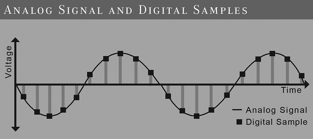
The single most important aspect of the digital domain is that a digital signal is not continuous like analog but discrete. To transfer an analog signal to the digital domain, it has to be sampled with an analog-to-digital (A/D) converter. This device takes in a sample at discrete time intervals (discretization) and replaces it with a sample value (quantization). This process is illustrated in Figure 16-1. The frequency at which this happens is called the sampling frequency or sample rate. Popular sample rates in audio are 44.1 or 48 kHz—but how high does the sample rate have to be? This is defined by the so-called Nyquist-Shannon sampling theorem. This theorem states that a signal can be perfectly reconstructed if the sample rate is greater than twice the bandwidth of the signal. Now you can see why the popular audio sample rates are higher than approximately 40 kHz—because the practical highest frequency a human ear can hear is 20 kHz! The other way around is also true: A signal to be sampled may not contain frequencies above Nyquist; otherwise, weird signal components will be generated, known as aliasing. The signal must be filtered first.
Digital-to-Analog Converter
Once the signal is in the digital domain, it is just a sequence of values that can be stored and transferred easily and without any quality loss, unlike an analog signal. And, of course, the signal can be manipulated in various ways. But sooner or later the signal has to be converted back to the analog domain with a device called obviously a digital-to-analog (D/A) converter. A D/A converter raises the output voltage to the value of each sample until the next samples hold. This produces a staircase-like signal, as shown in Figure 16-2.
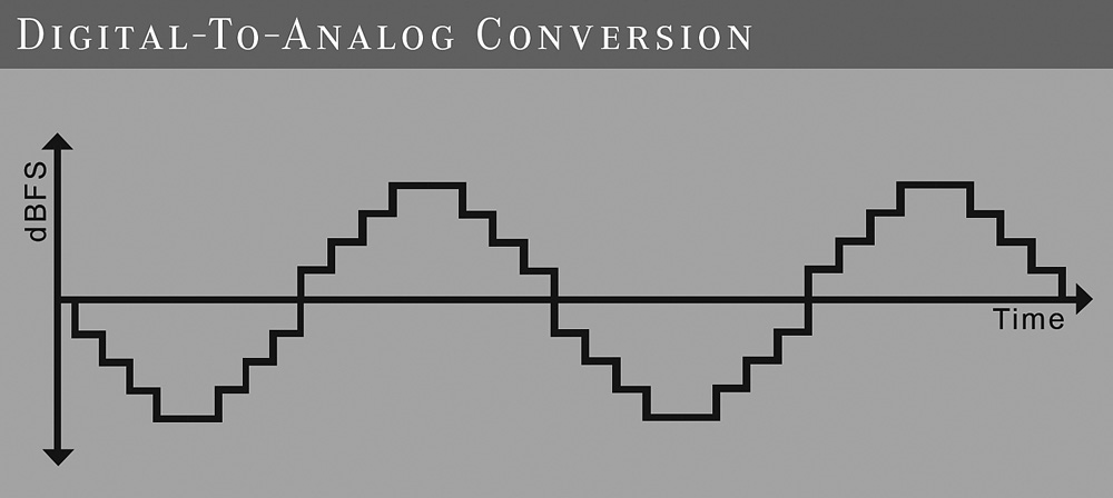
Although this signal looks a lot like the original signal, the hooked shape creates frequency components (harmonics) above the Nyquist frequency. Of course, this is not what we want, and therefore, we need to filter all frequencies above the Nyquist frequency to perfectly restore the original signal.
Impulse Response
An impulse response is the response of a system to a very short signal, called an impulse. Why is this important, you might ask? Well, with this impulse response you can simulate the reaction of this system to a given signal. This process is called convolution. A popular implementation is a convolution reverb. Loading the impulse response of a reverb device into a convolution processor together with a dry audio signal will result in a reverbed audio signal, just as if the signal went through the real thing. To get a perfect simulation, the system has to be linear and time-invariant. Needless to say, the greatest sounding reverbs are far from linear and time-invariant.
Filter Types
IIR
This stands for infinite impulse response, infinite referring to a never-ending feedback loop. This filter type is very similar to an analog filter; in fact, you can quite easily transform an analog filter into an IIR filter with a mathematical process called bilinear transformation. Figure 16-3 presents a diagram of an IIR filter. If you feed an IIR filter with an impulse signal, it will output an infinite number of nonzero values.
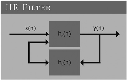
The output Y is fed back through H to the input. This inherently means that anything happening on the input will theoretically be present in the output forever, hence the term infinite. In practice, the response of a stable system will fade away into the noise.
One of the problems that can arise with an IIR filter is instability because of the feedback. Mathematically, this can be explained as shown in Figure 16-4.

H is the transfer function. For a very simple IIR filter, H may look like that shown in Figure 16-5.
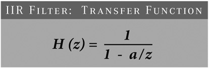
FIGURE 16-5 IIR filter transfer function. Z is a so-called complex number and is another way to describe the frequency. A is a property for this given IIR filter.
A problem arises when the frequency component Z results in a division by zero! In this simple filter we have a 1 pole at Z × A. With careful placement of the poles, such a filter can be made stable.
As mentioned earlier, an analog filter can easily be transformed into an IIR filter. As a result, most classic analog filter designs have a digital counterpart. Each filter has its strengths and weaknesses. Here are a few popular design types with their typical characteristics.
Butterworth Filter This is a so-called maximally flat filter design with a smooth transfer from the pass band to the stop band. The frequency response in the pass is flat.
Chebychev Type I Filter This has a steeper transition between the pass band and stop band than the Butterworth filter. The stop band is as flat as possible, but the pass band has a ripple.
Chebychev Type II Filter Again, this has a steeper transition than the Butterworth filter. In contrast to the Chebychev type I filter, this type has a flat pass band and a ripple in the stop band.
Elliptical Filter This has a very steep transition between the pass and stop bands but with a ripple in both bands.
Most IIR filters start behaving differently than their analog counterparts around the Nyquist frequency owing to a mathematical effect called prewarping—but what if you also want an accurate response at these frequencies? A common approach is the use of upsampling. Here the audio gets upsampled to a higher sample rate, moving the problem far above the original Nyquist frequency. After that, the signal is downsampled again to the original sample rate, and the problem is gone. Of course, implementation of the upsampling algorithm needs to be very precise; otherwise, the end result is worse than before.
FIR
A FIR filter has a finite inpulse response. This means that the response Y to an impulse X will last a predetermined time and after that becomes zero. As you can see in Figure 16-6, a FIR filter doesn’t have a feedback loop like an IIR filter. This means that a FIR filter is inherently stable.
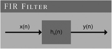
FIR filters are relatively easy to design and implement, especially in hardware. Another advantage of a FIR filter is that it can have exactly linear phase. A system has linear phase when its impulse response is symmetrical. Figure 16-7 shows a linear-phase filter.
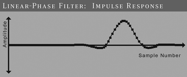
A FIR filter can have this property very easily because the filter impulse response is defined directly in the design. With an analog or IIR filter, this is impossible because of the feedback loop causing the impulse response to depend on what happened in the past. This is why you won’t find linear phase in nature. Also, with a linear-phase filter it takes a while before the input signal reaches the output, and this causes a delay. Some people find this reason enough to disqualify linear-phase filters for audio, whereas others find these filters to be very transparent because there is no phase distortion.
Are there any other disadvantages to FIR filters? Of course there are. For example, a FIR filter needs a higher filter order than an IIR filter to get the same response. This means that it needs more memory and computational effort.
Design and Implementation
In equalizers you can find various types of filters. Low- and high-pass, peaking, and shelving filters, and so on, whether FIR or IIR. While it is hard to generalize, I think it is safe to say that a digital filter needs to be stable under all conditions and implemented properly before it can be used successfully as an equalizer or any other filter.
Stability is relatively easy to achieve when carefully designed, but proper implementation is harder to do. This depends largely on the chosen hardware platform, floating- or fixed-point arithmetic, engineering skills, and so on. This is where manufacturers can really make a difference. A filter design may look fantastic on paper, but when implemented poorly, it will fail to produce excellent results.
In an analog equalizer, the electronic parts are very important. There are many types, and there is a lot of difference in quality between brands. Also, capacitors will change over time. In the digital domain, we don’t have this trouble, but unfortunately, we have to deal with other problems. We have to take care of resolution, sample rate, jitter, aliasing, and so on.
Conclusion
We have just scratched the surface of digital signal processing here. But there are many more possibilities, and we have to embrace them. When it comes to filters, in the digital domain we can simulate analog filters, create new ones, and also make filters that can’t even exist in the analog domain. With proper design and implementation, a digital filter can work as good as an analog filter and even better!
Cornelius Gould is a former broadcast engineer most recently for CBS Radio in Cleveland, OH. He now is the team leader for the Omnia audio processor brand and is the codeveloper of the Omnia 11 broadcast processor, used in most FM radio stations across the United States.
We learn from Cornelius Gould about how we can best prepare recordings for radio play and avoid known problems.
Optimizing Audio for Radio
Cornelius Gould, Audio Processing Developer
Omnia Audio, Cleveland, OH
There are several things that take place when a recording is played on the radio. First, general managers and program directors typically make a decision about which recordings a radio station will play. Then the station will download the music into its systems from a broadcast music download service (such as Play MPE and New Music Server). Then, for tracking and royalty-payment purposes, the station reads the ISRCs into its system, which may come from a database or be entered manually. ISRCs are virtually never extracted from any metadata or disc. The station also may obtain a CD of the recording, but typically music arrives by means of a digital delivery service. In the future, broadcast music download services may begin accepting and distributing 24-bit masters for radio, especially now that such masters are already being generated by mastering engineers for Apple’s Mastered for iTunes program. I know of some broadcasters who already use 24-bit recordings exclusively, although they personally work to obtain them. Today broadcasters concerned with maintaining quality source material mostly use 16-bit/44.1-kHz WAV files for broadcast.
Radio stations have their own unique selection of processors in front of the broadcast transmitter. There are many such processors typically called a broadcast processors, such as our line of Omnia radio processors.
Before the recording is sent to the transmitter, it must be processed in accordance with the legally instituted preemphasis curve—an equalization filter. The preemphasis curve is an early form of noise reduction still in use today, in which the high frequencies of an audio signal are boosted by some amount for transmission over a delivery system. The reverse of the curve is applied inside the listener’s radio, which is called deemphasis.
This process creates brief high-frequency “peaks” that are applied to aggressive peak-limiting processes to reduce the peak energy. This process historically has been performed using clipping processes, although some processors employ some degree of sophisticated dynamic limiting action as well.
When a mastered recording is overly bright, the preemphasis processing can have a negative effect on the perceived on-air quality of the recordings. The peak energy of the high-frequency energy can become excessively high, causing a “smeared” sound to the high-frequency components. In some cases, severe clipping artifacts on the sibilant sounds, cymbals, and other high-frequency content are heard. Overly bright recordings have become more prevalent, especially with the limitless nature of digital recording, and generally were at a better level for radio during the early 1990s.
Broadcast processors perform various processing functions, including automatic gain control (which mimics manual gain riding and operates over a large dynamic range), multiband leveling, dynamic limiting, equalization, preemphasis filtering, brick-wall limiting, and more. They are typically set up by the manufacturer or the radio station’s engineers. This processing is a type of automatic/algorithmic mastering, if you will. Sometimes anomalies happen with this compression, as with Britney Spear’s “I Wanna Go.” This song contained a relatively loud 20-kHz tone in the chorus. This tone causes higher amounts of gain reduction on the high-frequency bands in many multiband broadcast audio processors. This tone unintentionally causes the chorus to sound dull (like AM radio) compared with the verse on the radio.
Other songs (such as Bruno Mars’ “It Will Rain”) have significant subsonic components (around 3 to 10 Hz). These components cause some radios to mute during the intro because the radios think they are not tuned to a frequency given that the subsonic energy looks similar to a condition that translate to the radio as meaning “I’m not tuned in.”
A useful tool to have during mastering would be some sort of fast Fourier transform (FFT) audio spectrum display to ensure that there are no unintentional tones or noises that fall at the extreme frequency-response edges that may cause a problem for songs when presented to radio stations.
Phase rotators are very typically used in broadcast. These help to increase the symmetry of a waveform, especially vocals. When a waveform is recorded, especially a voice, it can create an asymmetrical waveform. When clipping/brick-wall limiting techniques are applied, the sound quality is harsher if the source is asymmetrical. Phase rotators always degrade the audio to some degree but provide a benefit of more symmetrical waves and provide a less abrasive, pleasant experience for the listener.
CDs that are mastered with hard clipping for greater loudness can sound extra distorted on the radio because the clipped waveforms in the recordings are “spun around” in the phase rotator and can cause overload distortion in the front end of some audio processors. It is generally better to use look-ahead limiting where possible versus hard clipping.
Radio broadcasters are engaged in something not unlike the loudness wars of the mastering world. Stations compete between themselves with loudness levels stemming from the same reasoning behind the loudness wars. This means that broadcast processors must raise loudness, which is done primarily by clipping. The automatic/algorithmic mastering contained in the broadcast processor uses some of the same types of tools used by mastering engineers. Because of this, if mastering engineers leave some dynamics for the broadcast processor to work with, it will result in a better experience for the radio listener. Perhaps in the future this may be done by mastering engineers delivering a different version to the broadcast music download services, but today everyone gets the same version. Songs mastered with a maximum average loudness level of –8 or –9 dB root-mean-squared (RMS) may be ideal for radio playback. This would be according to a true RMS meter such as a Dorrough loudness meter, which would be –11 or –12 dB RMS on most other digital meters such as the Waves PAZ and those built into most digital audio workstation (DAW) software, which uses the more common RMS + 3.
In conclusion, there are several things mastering engineers can do to ensure the best sound quality on the radio. Mastering engineers should be careful not to make recordings overly bright or sibilant, which could degrade the sound quality owing to the preemphasis curve. Because of the loudness competition between radio stations, dynamic recordings will simply sound best on the radio and will be as loud as overcompressed recordings. Finally, mastering engineers should consider providing less “processed” versions of songs, and maybe even higher-bit-rate source material should be used by radio stations in the future, which is entirely possible with today’s systems.
Jeff Powell is a veteran recording/mix engineer, producer, and vinyl-cutting engineer. Powell has enjoyed the success of multiple gold and platinum records, including five Grammy Award–winning projects. His credits include albums such as Stevie Ray Vaughan and Double Trouble’s “Live at Carnegie Hall,” Big Star’s “In Space” and the Afghan Whig’s “Gentlemen.” He first began to learn the skill of vinyl lacquer cutting from legendary vinyl-cutting engineer Larry Nix, who began as the house mastering engineer at Stax Records and later founded L. Nix Mastering. Powell now performs direct vinyl transfers on a classic Neumann VMS70 lathe.
Jeff gives us the scoop on how to prepare a recording to be cut to vinyl. He shares details about the process with a focus on ideas that could affect a mastering engineer’s work.
Premastering for Vinyl Cutting
Jeff Powell, Direct Vinyl Transfer Engineer
Engineer for Stevie Ray Vaughn, Bob Dylan, and Many More Artists
There are a few key things to understand to best prepare recordings for master vinyl lacquer cutting. First, let’s cover a general overview of the process from the final mix in the studio to putting a finished record on the turntable for a listen. Later there will be more detail about the various steps.
The band, the mix engineer, and the producer mix the record, assemble a final sequence, and send it to their mastering engineer of choice. The mastering engineer processes the mixes and then assembles a final Red Book CD master and/or digital master. The CD master is then sent to the label or pressing plant to be manufactured. If the recordings are also intended for vinyl release, the mastering engineer will create another set of files optimized for cutting vinyl that are used by the cutter to make a master lacquer. The master lacquer is cut, inspected, and immediately shipped to the plating and pressing plant (plating and pressing services are usually provided by the same company). After the plating process, metal parts are created and used to stamp out five to seven test pressings, which are sent to the band, label, original mastering engineer, management, and the cutting engineer. Everyone listens, and if everything sounds great, the records are pressed.
There are several suggestions mastering engineers can make to the mix engineer and producer to get the best results from vinyl. This includes several things to avoid: overcompression of the mix, hard-panned drums or bass, piling on the giant low-end subfrequencies, and excessive brightness in the high-end frequencies (especially watch the hi-hat and cymbals for harshness and de-ess the vocals). In the most general sense, if both the mixer and mastering engineer are aware of these basic things, it will provide a big head start in making a great master source for the cutter to work with.
There are also some things a mastering engineer can do to help create the best-sounding vinyl. The most important thing to realize is that mastering processing doesn’t have to change much, except for the final stage. The mixes should be processed as normal for a CD master, more or less, but at the end, the digital limiter should not be used. The level should be reasonably near 0 VU. This can be a real challenge if clients are turning in mixes with no dynamic range.
Luckily, most of my projects come in at 24 bits/96 kHz. It is always best to provide the cutter with at least 24-bit depth recordings regardless of the sample rate, whenever possible. The worst thing, next to someone asking me to cut an MP3 file to vinyl, is to give me a final Red Book 16-bit/44.1-kHz finished CD to fit onto a vinyl record the best I can. When this happens, the first thing I have to do is turn the level down by 7 to 10 dB to even come close to making it fit. There are physical limits to what can fit onto a side of a vinyl record. This brings up the issue of side length, one of the most important aspects of helping the final record to sound beautiful.
Depending on the level and density of the material, a rule of thumb is to keep a 33⅓ rpm 12-inch LP at less than twenty minutes a side in length. Sixteen to eighteen minutes is ideal to make it sound really good. For a 45 rpm 7-inch single, try to keep the sides less than four minutes long. From three to three and a half minutes in length will usually sound great. In general, the shorter the side, the better it will sound.
What If the Songs Will Not Fit?
It seems to be fairly common for modern records to be longer than 40 minutes, so here are some things to think about when preparing the master for vinyl if the sides are too long. All these options entail going back to the producer and letting him or her, the band, and/or the label decide what they want to do if it won’t fit.
Remove Songs
It’s pretty easy to say that the most unpopular suggestion is to remove a song (or two) from the vinyl version of the album. Most bands include download codes when you buy a vinyl record, so it can be a big problem when something slated to be included as a free download has to be cut from the vinyl record.
Shorten Songs
Shorten the songs by having the mixes faded out earlier than on the CD version.
Edit
Do some creative editing to cut out sections of the arrangement that are repetitive or don’t make the song better.
Change the Sequence
Change the sequence from the CD version to try to balance out the running times of the sides. Within a minute or less of each other is good practice, but if one side is more than a couple of minutes longer than the other, consider putting more of the less dynamic, less bass/low-frequency energy–filled, quieter songs on one side.
Cut It to Four Sides Instead of Two
This doubles the cost of cutting, plating, and manufacturing, but it sounds fantastic. If the record is more than 43 minutes long with shortened fades, edits, and lowered levels, the principals should think about going for four sides, putting it all back in, and getting a higher-fidelity result. If the side lengths fall into the right range, the LP can be cut at 45 rpm for even better fidelity, which usually sounds fantastic.
Processing for Master Lacquer
When I am cutting vinyl, making what is called a direct transfer, there are about five main things I can do with processing to get the master lacquer cut with the best potential sound quality. All these processes are subjective.
High-Frequency Limiting
This is usually either bypassed or set in a minimal way to catch high-frequency transients that could cause a skip or damage the cutter head.
Low-Pass and High-Pass Filtering
Filtering at 40 Hz and below is usually a great starting place. If the cutter is having trouble fitting the material on a side, rolling off more low end can be a big space saver.
Level Adjustments
This is probably the main thing a cutter can do to save space if there is trouble fitting the material on a side.
Elliptical EQ
This is a crossover that moves all low frequencies below a preset frequency to the center. Elliptical EQs are used this way to stop excessive lateral movement of the stylus if there is too much low-frequency energy on one side. This happens, for instance, when the kick drum, bass guitar, or bass synthesizer is panned to one side.
De-Essing
I prefer not to have to do this by the time it gets to me. If there is a sibilance problem, I feel that it is better and more specifically handled by the mastering engineer and even more so by the mixer. In other words, it’s a shame to have to de-ess your whole mix because, for example, the hi-hat is too loud. It takes other good stuff in that frequency range down with it.
Cutting the Master Lacquer
With all this in mind, let’s go through the process of cutting the master lacquer. First, I listen through the material and then figure out how to best set up the lathe for the best sound within the physical limits mentioned previously. I then do a simulation run on the lathe, letting it run through the side, manually banding between songs—all without actually dropping the cutter head and making a cut. These are called dummy runs. I do this and then make adjustments to the processing until I can get the recordings to fit, sounding the best it can. I also usually do a test cut on scrap lacquer and listen back to it. I often skip around and cut passages that I think are potential trouble spots and see how they play back before I commit. Once this happens, I bring out a blank master lacquer from its dust-free box. I visually inspect it for flaws, and if I do not see any, I put it on the turntable, turn on the suction, and cut the master lacquer.
The master lacquer cannot be played once cut. I inspect it with a microscope for overcuts or flaws. If there are none, the last thing to do is hand scribe the matrix number and the side info in the space between the label and the run-out groove and then immediately box it up and ship it out to the plating/pressing plant. Clients should be sure that their order and contact information have been received correctly with the plant before the master lacquer is cut. This is because a master lacquer degrades if it sits in a box for days. Clients should be made aware of this as early as possible. The cutting should not start until the shipping and ID information is given to the vinyl cutter so that shipping can happen immediately.
Weeks go by, the test pressing comes in the mail, and you listen.
David A. Hoatson is the cofounder and Chief Software Engineer of Lynx Studio Technology, Inc. Lynx equipment is considered to be of the highest quality, with several popular audio interfaces used for professional mastering.
This contribution helps us to understand the important differences between using ASIO and WDM drivers.
ASIO versus WDM
David A. Hoatson, Cofounder and Chief Software Engineer
Lynx Studio Technology, Inc.
History and Implementation
ASIO is an acronym for Audio Stream Input/Output, which was developed primarily by Stefan Scheffler of Steinberg (now owned by Yamaha) starting around 1997. It is primarily a user-mode application programming interface (API), meaning part of the audio card driver is loaded by the application and uses the same address space as the application. This also means that the driver must be written in (at least) two parts—the user-mode component that is loaded by the application and the kernel-mode component that is used to talk to the audio hardware. I say “at least” two parts because in 64-bit environments there must be a 64-bit kernel-mode driver, a 64-bit user-mode driver for native 64-bit applications, and a 32-bit user-mode driver for 32-bit applications. ASIO is currently supported only on Windows operating systems. Originally it was supported on Mac OS 9 as well, but it was never ported to OS X (although there are no technical reasons why it couldn’t be).
ASIO provides a direct connection between the application’s audio engine and the audio hardware. For most implementations, hardware manufactures allow the audio application to write directly into the buffer that the audio hardware is accessing to play and record the audio. This means that there are no intermediate processes that might affect audio quality or processor performance. ASIO is implemented as a Ping-Pong buffer, where buffer A is being filled (or emptied) by the hardware, and buffer B is being processed by the application. Once the hardware and driver are done with buffer A, it signals the application (using an interrupt and/or event) that it is switching to buffer B, and the application can start servicing buffer A. If done properly, the application has the maximum amount of time to process the audio buffer before it becomes active by the hardware. Glitches can occur in the audio when the application doesn’t have enough time to process the buffer before that buffer becomes active. Reasons for this are varied: too many active plug-ins, too small a buffer size, and other hardware or software stealing the processor away and preventing the audio application from completing its task, just to name a few.
WDM is an acronym for Windows Driver Model, which was developed by Microsoft starting around 1997 to unify drivers between Windows 98 and Windows 2000. Contrary to popular belief, WDM drivers actually present no API directly to applications. All calls from the application must use the API from Microsoft Multimedia Extensions (MMEs or waveOut); DirectSound, or Direct Kernel Streaming. With the introduction of Windows Vista, Microsoft added a fourth API to replace Direct Kernel Streaming: WASAPI. Windows then interprets these calls into a single API that is sent down to the kernel-mode WDM audio driver stack and on to the audio driver. The audio is reprocessed and may be mixed or sample rate-converted by the Microsoft code.
Originally, there were two types of WDM drivers: WaveCyclic and WavePCI. WaveCyclic was intended for use with audio hardware that uses transfers from a fixed location in memory. WavePCI was intended for use with audio hardware that can perform scatter/gather transfers to or from any location in memory. With Windows Vista and Windows 7, Microsoft added WaveRT (wave real time) that works much more like ASIO.
WDM (when used with MME or DirectSound) always has an intermediate layer provided by Microsoft that affects performance in terms of both audio quality and processor usage. There are few applications that use Direct Kernel Streaming (Cakewalk SONAR is the only one that comes to mind), which can bypass Microsoft’s audio layer when using WDM. With the addition of WASAPI in Windows Vista and beyond, Microsoft has allowed application developers to more easily directly access the audio buffer that the hardware is accessing to play and record audio. This also requires a change in the driver to use the WaveRT model. Along with WaveRT came a way of allowing the driver to signal when it needed service instead of relying on the application and/or operating system to poll the driver to determine when service was required. When the application asks the driver to allocate the audio buffer with notifications, it greatly improves the reliability of audio playback using the Windows audio subsystem.
Sonic Differences
The audio driver and hardware’s job is to transfer the audio from the application to the analog domain in the most efficient and transparent way possible. In a perfect world, the driver model used should have no effect on audio quality or computer performance. Unfortunately, this is not always the case. This is why ASIO has dominated the professional audio market over the past decade. It provides a low-latency way to transfer audio from the application to the audio hardware in a very efficient manner. It also keeps other parts of the operating system from altering the audio stream.
WDM has been plagued with different issues in each version of the operating system. Windows 2000 and Windows XP both suffered with KMixer touching each sample as it passed through the system, sometimes with horrible sonic consequences. Certain versions of Windows Vista suffered from truncation issues, where the audio subsystem would be given 24-bit audio but would truncate it to 16 bits (no dither) even though the audio card could play 24 bits. Windows 7 with WASAPI in exclusive mode and a WaveRT driver is really the first real alternative that promises audio performance similar to that of ASIO. The main advantage that ASIO has is its mono-channel structure. With a multichannel audio device, ASIO treats each channel as its own independent mono channel. If an application wants to do eight-channel operation, it sees eight mono channels. If it then wants to do 16-channel operation, it sees 16 mono channels. With a WDM multichannel device, the channels are interleaved into a single stream. This means that going from 8 to 16 channels causes the device to need to be switched into 16-channel mode at the operating system level, which may not be possible (Windows only knows about 7.1) or be very difficult to achieve. Windows 7 still suffers from certain bugs that affect the audio quality when using WDM multichannel devices. Specifically, when in 16-bit multichannel mode and playing back a stereo file, there is some audio being played back (at a very low level) on channels that should not be active.
Zero-Latency Monitoring
ASIO provides a feature called direct hardware monitoring that allows applications to directly control the feed through audio (from input to output) in a standardized way. This allows end users to set up custom mixes for headphones or studio monitors while recording without the latency caused by going through the record and playback buffers. Cubase, Nuendo, Samplitude, Sequoia, and Reaper all support direct hardware monitoring.
Although WDM provides a topology driver that could provide a similar feature set to direct hardware monitoring, each audio card manufacturer is free to implement the driver however it desires. This means that there is no standardized way for the audio application to present zero-latency monitoring using WDM. The end user is left with monitoring through the record and playback buffers, which may add several milliseconds of delay to the headphone mix. Many performers find this unacceptable.