
8
Presentation
The traditional television set with a CRT and a modest loudspeaker will continue for some time because it can be made at very low cost and is adequate for watching certain types of program. However, convergent technology allows the production and delivery of high-quality image and surround-sound data, leading to a requirement for presentation equipment which can do justice to it. The requirements of an electronic cinema will be for a large bright picture with adequate audio power, whereas in the home cinema there are additional constraints such as cost and physical size. High definition in the home will not succeed until the equipment can be made sufficiently compact. This is true not only for displays, but also for loudspeakers which traditionally have been large and unattractive. Surround sound requires the user to have five or more loudspeakers and with traditional technology this will be unwieldy if good quality is required, or give poor sound if size limits are imposed. The solution is to use active loudspeaker technology, as decribed below, to obtain sound of high quality from small enclosures.
8.1 Display principles
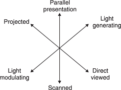
The large number of display technologies available all have rather different characteristics, both strengths and drawbacks, and to date no one technology is ideal. Figure 8.1 shows some of the ways in which displays can be categorized. The light may be generated by the display itself, or the display may modulate light from a separate source. This modulation mechanism may be infinitely variable, or analog, or it may be binary in which case some form of pulse width or duty cycle modulation becomes necessary. Displays may be parallel, where the whole image is presented simultaneously, or scanned, where a single light spot travels at high speed to cover the whole picture area in one frame period. Some types of display are in the form of a projector, requiring a cinema-type screen, whereas other types are themselves the screen.
The applications of displays are almost unlimited and this is partly responsible for the wide range of technologies. In portable applications, weight and power consumption are overriding concerns whereas in critical monitoring areas colorimetry, level resolution, spatial and dynamic resolution are more important. In projection systems, high light output is a goal so that a large screen can be used.
8.2 The monochrome CRT
The cathode ray tube (CRT) is a relative of the vacuum tube and is shown in Figure 8.2. Inside a glass envelope a vacuum is formed initially by pumping and completed by igniting a material called a getter which burns any remaining oxygen to form a harmless solid. The pressure differential across the tube face results in considerable force. For example, the atmosphere exerts a force of about a ton on the face of a 20-inch diagonal tube. As glass is weak in tension the tube is strengthened with a steel band which is stretched around the perimeter of the screen. Figure 8.3 shows that the tube face is generally slightly domed outwards so that the thrust due to atmospheric pressure is converted to a radial out-thrust to which the steel band provides a reaction. The necessity to withstand atmospheric pressure over the screen area puts an upper limit on the size of CRTs. Large CRTs are necessarily heavy.
The cathode is coated with a barium compound and contains an insulated heating element which raises its temperature. This heating causes the coating to emit electrons. The electrons have negative charge and so are attracted towards an anode which is supplied with a positive voltage. Between the cathode and the anode is a wire mesh grid. If this grid is held at a suitable negative voltage with respect to the cathode it will repel electrons from the cathode and they will be prevented from reaching the anode. If the grid voltage is reduced the effect diminishes and some electrons can pass. The voltage on the grid controls the current.
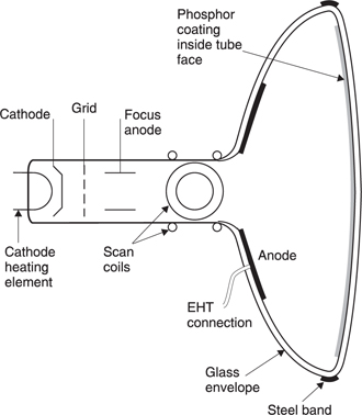
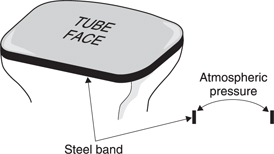
Figure 8.3 The thrust due to atmospheric pressure is resisted by doming or curving the tube face. This converts the pressure load into an out-thrust which can be resisted by a steel band stretched around the tube. Domed buildings are held up in much the same way. The large forces involved place practical limits on the size of CRT which can be made before it becomes too heavy to be useful.
The anode contains a hole through which the electrons emerge in a beam. They are further accelerated by more electrodes at successively higher voltages, the last of these being the EHT (extra high tension) electrode which runs at 15–25 kV. The electron beam strikes the inside of the tube face which is coated with material known as a phosphor. The impact of energetic electrons causes electrons in the phosphor to be driven to higher, unstable valence levels, and when they drop back, photons of a specific wavelength are released. By mixing a number of phosphor materials white light can be obtained.
The intensity of the light is effectively controlled by the intensity of the electron beam which is in turn controlled by the grid voltage. As it is the relative voltage between the cathode and the grid which determines the beam current, some tubes are driven by holding the grid at a constant voltage and varying the voltage on the cathode. The electron impact may also generate low-level X-rays and the face of the tube will be made from lead glass to absorb most of them.
The relationship between the tube drive voltage and the phosphor brightness is not linear, but an exponential function where the power is known as gamma. The power is the same for all CRTs as it is a function of the physics of the electron gun and it has a value of around 2.8. As was seen in section 6.8, the gamma function of a CRT follows roughly the same curve as human contrast sensitivity. Traditionally video signals are predistorted at source by an inverse gamma, such that the gamma characteristic of the CRT will linearize the signal.
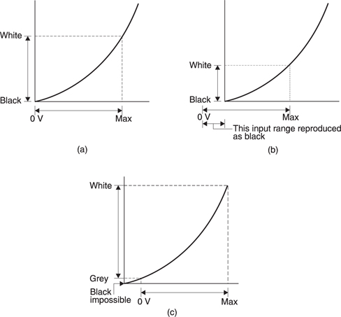
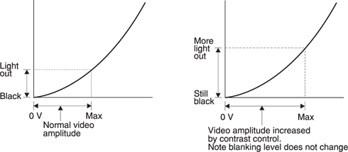
Virtually all CRT-based displays are fitted with two controls conventionally and misleadingly marked brightness and contrast. Figure 8.4(a) shows what the ‘brightness’ control actually does. When correctly set, the lowest drive voltage, i.e. blanking level, results in the electron beam being just cut off so that the CRT displays black. If the ‘brightness’ is set too low, as in (b), the CRT cuts off prematurely and all inputs below a certain level are reproduced as black. The symptom is decribed as black crushing. If the control is set too high, as in (c), video blanking results in a substantial light output such that all displayed images are superimposed on a grey level.
It should be clear that there is only one correct setting for a brightness control because it is in fact a tube bias or black level control. In order correctly to set a black level control the grey stepped scale of a test card may be used. The black level control is advanced until the black part of the scale appears obviously grey, and then it is turned down until the the black part of the scale is just displayed as truly black, but not so far that the darkest grey step next to it becomes black as well. Once set in this way the CRT is correctly biased and further adjustment will only be needed if component values drift.
Special test signals exist in the television industry to assist with monitor alignment. One of these is known as PLUGE (Picture Line-Up GEnerator), pronounced ‘plooj’.
The PLUGE signal contains a black area in which there are two ‘black’ bars which sit typically ±20 mV above and below black level. If the ‘brightness’ control is adjusted downwards from an initial excessively bright setting, it will be found that the two bars become indistinguishable from the black background, due to black crushing, at slightly different times. The correct setting is achieved when one bar has vanished but the other is still visible.
The ‘below black’ pulse in the PLUGE signal is technically illegal because it occurs during the active line and gamut-monitoring equipment may issue an alarm or error condition if asked to pass such a signal. This is normal.
The action of the ‘contrast’ control is shown in Figure 8.5. This has the effect of increasing the amplitude of white signals whilst leaving black level unchanged. Thus in order to increase the brightness of a correctly biased display, the contrast control should be advanced. If the contrast is excessive the electron beam becomes larger in diameter and the resolution of the display is reduced. In critical monitoring, a light meter is used in conjunction with a peak-white input signal to allow a standard brightness to be achieved. The PLUGE signal contains a peak white area to assist with this.
In practice the contrast of a CRT is also affected quite badly by ambient lighting. With black input voltage cutting off the beam, the brightness of a CRT cannot fall below the brightness of reflected ambient light. Thus ambient light reduces contrast. For best results all display technologies should be viewed in subdued lighting where the best combination of contrast and resolution will be obtained. As all CRT tubes are reflective to some extent, it is important to ensure no bright objects are positioned where they could be seen reflected in the screen. Some CRTs are provided with non-reflective coatings which have a beneficial effect.
The electron beam is an electric current and this can be deflected electrostatically by voltages applied to plates at the neck of the tube, or magnetically by coils outside the tube. Electrostatic deflection is fine for the small tubes used in oscilloscopes, but the large deflection angles needed in TV tubes can only be obtained with magnetic deflection.
The horizontal deflection coils are generally driven by a transformer. During the flyback period the flux in the transformer changes rapidly and this can be used to generate the EHT supply by providing an additional winding on the transformer which feeds a high-voltage rectifier. There is some evidence to suggest that the X-rays or magnetic fields from CRTs may present a health hazard after prolonged exposure.
The rate at which the electron beam can retrace is limited by the inductance of the scan coils which limit the rate at which the deflection current can change. The active line has to be made considerably shorter than the line period so that sufficient retrace time is available. Losses in the transformer put a practical limit on the line scanning frequency which can be used, although better materials could overcome this.
Normally the horizontal and vertical retrace is invisible, but certain monitors have the facility to shift the scan phase with respect to incoming syncs by part of a line and part of a field. The result is that the blanking periods become visible for inspection on the screen in the form of a cross, hence the term pulse cross monitor.
8.3 The colour CRT
In order to display colour pictures, three simultaneous images must be generated, one for each primary colour. The colour CRT does this geometrically. Figure 8.6(a) shows that three electron beams pass down the tube from guns mounted in a triangular or delta array. Immediately before the tube face is mounted a perforated metal plate known as a shadow mask. The three beams approach holes in the shadow mask at a slightly different angle and so fall upon three different areas of phosphor which each produce a different primary colour. The sets of three phosphors are known as triads. Figure 8.6(b) shows an alternative arrangement in which the three electron guns are mounted in a straight line and the shadow mask is slotted and the triads are rectangular. This is known as a PIL (precision-in-line) tube). The triads can easily be seen upon close inspection of an operating CRT.
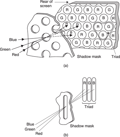
Figure 8.6 (a) Triads of phosphor dots are triangular and electron guns are arranged in a triangle. (b) Inline tube has strips of phosphor side by side.t
During the manufacturing process the shadow mask is fitted and the tube is assembled except for the electron guns. The inside of the tube is coated with photoresist and a light source is positioned at the point where the scan coils would deflect an electron beam such that the resist is exposed in all locations where one colour of phosphor should be deposited. The process is repeated for each phosphor.
In early tubes the space between the phosphor dots was grey. Later tubes replaced this with black in order to reduce reflection of ambient light and thereby increase contrast and apparent sharpness.
When the tube is completed, the scan coils have to be installed in exactly the right place otherwise the correct beam geometry will not result and beams may fall on part of the wrong phosphor in the triads. Adjusting the scan coils to ensure correct triad registration is called the purity adjustment. The shadow mask is heated by electron impact in service, and is not readily cooled because it is in a vacuum. Should the shadow mask overheat, it may distort due to thermal expansion and damage the purity. This effect limits the brightness of shadow mask CRTs. Purity can also be damaged by stray magnetic fields which may magnetize the shadow mask. Most monitors incorporate coils which degauss the shadow mask when the unit is first switched on. Many loudspeakers produce stray magnetic fields sufficiently strong to affect nearby CRTs and it is advisable to use loudspeakers which have been designed to contain their fields. Leakage field control will be discussed later in this chapter.
The three electron beams must also be arranged to scan over exactly the same area of the tube so that the three images correctly superimpose. Static shifts of the beams can be obtained by the static convergence controls which register the three beams in the tube centre. All three beams are deflected by the same horizontal and vertical scan coils, and the geometry is such that there will be registration errors between the beams which increase with the deflection. These errors are cancelled by providing subsidiary individual scan coils for two of the beams with correction waveforms. This is known as dynamic convergence. In order to adjust the convergence, a test pattern which produces a white cross-hatch is used. If the convergence is incorrect, rainbow-like lines can be seen instead of one white line. The inline tube has the advantage that the dynamic convergence waveforms are simpler to generate.
8.4 The projection CRT
A television projector may be made by using a similar optical system to a film projector in which the film in the gate is replaced by the face of a CRT. The cost of lenses means that the CRT has to be fairly small. This results in a high magnification factor between the CRT and the screen, requiring very high resolution on the CRT face. Obtaining enough light is a problem and normally driving a CRT at high beam currents will result in spreading of the spot which reduces resolution. Both of these problems are addressed at once by using three tubes; one for each colour. Each tube is essentially a monochrome tube in which the phosphor is selected to produce the appropriate primary colour. The approach needs no shadow mask and this improves efficiency and resolution.
Each tube generally has its own lens and these are usually mounted in a horizontal line so that the depth of the unit is minimized. This is an advantage when it is mounted from a ceiling. The geometry of three separate and displaced optical systems is such that the three primary images do not naturally superimpose or converge on the screen. Figure 8.7 shows that the lateral offset of the outer beams causes ‘keystoning’ in which the images are not rectangular. This is overcome by creating an inverse keystone raster on the CRT face by modifying the scan waveforms. In modern machines the convergence waveforms are generated by a microprocessor and the projector can converge itself automatically by generating test patterns through one lens whilst examining them through another.

Figure 8.7 The displaced tubes of a three-tube projector cause geometric errors on the screen known as keystoning. The raster on each CRT has to be predistorted to make the three images converge.
8.5 Plasma displays
In the plasma display the source of light is an electrical discharge in a gas at low pressure. This generates ultra-violet light which excites phosphors in the same way that a fluorescent light operates. Each pixel consists of three such elements, one for each primary colour. Figure 8.8 shows that the pixels are controlled by arranging the discharge to take place between electrodes which are arranged in rows and columns.
Figure 8.8 When a voltage is applied between a line or row electrode and a pixel electrode, a plasma discharge occurs. This excites a phosphor to produce visible light.
The advantage of the plasma display is that it can be made perfectly flat and it is very thin, even in large screen sizes. Plasma displays allow the practical size limit of CRTs to be exceeded.
The great difficulty with the plasma display is that the relationship between light output and drive voltage is highly non-linear. Below a certain voltage there is no discharge at all. Consequently the only way that the brightness can accurately be varied is to modulate the time for which the discharge takes place. The electrode signals are pulse width modulated.
Eight-bit digital video has 256 different brightnesses and it is difficult to obtain such a scale by pulse width modulation as the increments of pulse length would need to be generated by a clock of fantastic frequency. It is common practice to break the picture period up into many pulses, each of which is modulated in width. Despite this, plasma displays often show contouring or posterizing, indicating a lack of sufficient brightness levels. Multiple pulse drive also has some temporal effects which may be visible on moving material unless motion compensation is used. This will be considered further in section 8.8.
8.6 Scanning lasers
The laser is a useful source of light for colorimetric purposes because it is monochromatic. In theory three lasers of suitable wavelengths used as primaries could produce a range of colours which is unparalleled by any other technology.
The great difficulty with lasers is providing a scanning mechanism. This has traditionally been done with rotating multi-faceted mirrors, but a simple calculation will show that incredible rotational speeds are needed for high-definition images. The rotating parts have been mounted inside vacuum chambers to reduce air resistance and noise. As an alternative to scanning the whole image with a single beam, there have been attempts to divide the picture into strips, each of which has its own beam. This dramatically cuts the speed of the rotating parts, but it is very difficult to conceal the boundaries between the strips in the presence of motion and eye tracking. In order to do this properly a special motioncompensated signal processor will be required.
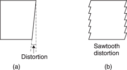
Figure 8.9 (a) Dynamic distortion of a moving vertical edge on a scanned display is minor and difficult to see. However, when the display is segmented so that it can be scanned by multiple beams (b), the dynamic distortion takes on an obvious sawtooth characteristic which requires non-trivial precompensation.
Figure 8.9 shows the problem. If a horizontally moving vertical line is displayed on a single beam scanned display, the dynamic distortion due to the use of a raster scan causes a small tilt of the vertical which is not noticeable. However, in a multi-beam system, the line takes on a sawtooth appearance which is very noticeable unless the image is predistorted in the opposite sense.
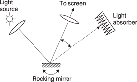
8.7 Micromirror projectors
In a micromirror projector, each pixel consists of a tiny mirror mounted on an equally tiny piezo-electric actuator which can tilt it when a control voltage is applied. Figure 8.10 shows that each mirror may be aligned so that it reflects light from a source onto the screen or into a light absorber. The mechanism is binary: either light passes to the screen or it is absorbed. In order to obtain a grey scale, each mirror is driven by pulses of variable width. Fortunately the mirror elements are so small that they can move extremely rapidly. The same dynamic effect as in plasma displays can occur with long pulses, but the micromirror display has the advantage that it does not generate light, it only modulates light from another source. A powerful light source can be used to keep the pulses short, improving dynamic resolution. The colorimetry of the micromirror projector is entirely a function of the light sources used.
8.8 Temporal effects
Different display technologies suffer from different temporal effects and this is responsible for some of the visible differences between display types.
Figure 8.11(a) shows that in conventionally projected film, the temporal impulse is basically rectangular due to the continuously burning arc lamp and the mechanical shutter. Figure 8.11(b) shows that the significant temporal aperture causes a loss of dynamic resolution because the image is smeared with respect to the tracking eye. However, the smearing also reduces the impact of background judder.
Some film projectors have discharge lamps which flash when the film is stationary, so that no shutter is needed. The period of the discharge is very short, leading to better portrayal of moving objects but worse background judder because the background is strobed at a different location in each frame with respect to a tracking eye.
Figure 8.12 shows that the CRT phosphor continues to emit light in an exponentially decaying curve for some time after the electron beam has passed. This is known as persistence. It might be thought that long persistence could be used to reduce flicker but this is not the case. As the impulse response is so peaky, an extremely long persistence figure is needed to stretch the peak significantly. This would damage the dynamic resolution. CRTs for television normally have quite short persistence and their dynamic resolution is very good. Flicker is best reduced by raising the frame rate.
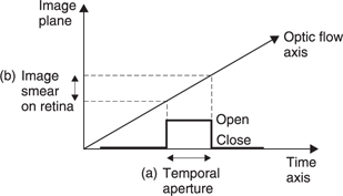
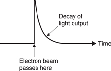
Figure 8.12 The temporal aperture of a CRT is an exponential decay. This short aperture gives good dynamic resolution which other display technologies struggle to match.
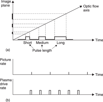
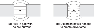
Figure 8.13 shows that if the eye is tracking a moving object on a plasma screen, viewing takes place on the optic flow axis. A dark area of the moving object will need only a short drive pulse, whereas a bright part will need a long pulse. The pulse length has a component along the optic flow axis giving rise to a dynamic effect in which moving lines appear wider the brighter they get. The solution is artificially to increase the display rate using a signal processor. This will need to be motion compensated. Instead of one long pulse, two shorter pulses will be used, reducing the dynamic effect. The perceived brightness is now a function of the sum of the two pulse widths and so a reduction in contouring is also possible.
The liquid crystal display has a very slow temporal response and the dynamic resolution is poor.
8.9 Display processors
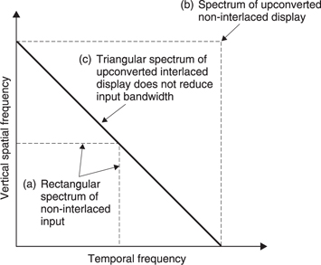
As was seen in Chapter 7, it is advantageous to use spatial and/or temporal oversampling in displays. Spatial oversampling requires that the number of pixels on the screen in both axes shall be greater than the number of input pixels. This has the effect of putting the aperture effect of the display outside the image passband. The greater spatial frequency of the pixels in an oversampled display is more readily filtered out so that the viewer perceives a continuous image.
If interlace has a place in modern systems, it is in display technology. Figure 8.14 shows a progressive scan transmission system with a rectangular passband (a). For display purposes, the signal could be upconverted or oversampled by a factor of two in both dimensions to reduce flicker and render the raster invisible. Upconverting to a progressive scan format would require the display line rate to be quadrupled as (b) shows. The use of interlace in the display upconvertor shown at (c) allows the full input passband through but only requires the display line rate to be doubled. The benefits of oversampling are achieved without the display becoming very expensive. Temporal oversampling by a factor of two raises the frame rate of an interlaced system above the CFF so that interlace flicker is no longer visible.
8.10 Optical filtering
When a projection display is used there will be a lens of some kind to focus the image onto the screen. This allows an opportunity which is not available to direct displays to use the lens as a reconstruction filter to make the individual pixels or raster lines blend into a continuous image. This requires an understanding of Fourier optics.
Figure 8.15 shows that when a given spatial frequency is illuminated by light of a given wavelength, the information carrying the spatial frequency is carried in wavefronts which leave at an angle to the optical axis. As the spatial frequency increases, the wavefronts become more oblique, whereas a reduction in spatial frequency makes the wavefronts less oblique.
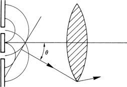
Figure 8.15 As detail in an image gets finer, the wavefronts describing it are angled further away from the normal.
The resolution limit of an optical system is reached when the wavefronts are too oblique to enter the aperture of the lens. Effectively the lens is acting as a spatial spectrum analyser. The lowest frequencies pass through near the centre of the lens, but as spatial frequency rises an annular band of increasing radius admits the light through the lens.
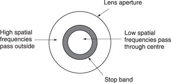
This gives rise to the possibility of using the lens as a bandstop filter. Figure 8.16 shows that if an annular mask is made with suitable inner and outer dimensions and installed adjacent to the lens, it will attenuate certain spatial frequencies whilst allowing lower and higher frequencies to pass. If the frequency concerned is the spatial frequency of the pixels or scanning lines, that frequency will be much attenuated on the screen.
In three-lens projectors where each lens handles one of the primary colours, each image is monochromatic and the fixed wavelength makes the optical filter work very well.
8.11 Loudspeaker principles
An ideal loudspeaker should produce a particle velocity proportional to the input waveform and so must have a wide, flat frequency response with no resonances and minimum linear and non-linear distortion. This, however, is only part of the design problem.
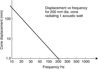
In all practical loudspeakers some form of diaphragm has to be vibrated which then vibrates the air.1 There are contradictory requirements. As can be seen in Figure 8.17, the SPL which the loudspeaker can generate is determined by the volume velocity. If the frequency is halved, the displacement must be doubled either by doubling the area of the diaphragm or by doubling the travel or some combination of both. Clearly a powerful loudspeaker which is able to reproduce the lowest audio frequencies must have a large diaphragm capable of considerable travel. As human hearing is relatively insensitive at LF a loudspeaker which can only reproduce the lowest audible frequencies at low power is a waste of time.
Unfortunately any diaphragm which has sufficient area for lowfrequency use will be too large at the highest audio frequencies resulting in beaming or high directivity which is undesirable. One solution is to use a number of drive units which each handle only part of the frequency range. Those producing low frequencies are called woofers and will have large diaphragms with considerable travel whereas those producing high frequencies are called tweeters and will have small diaphragms whose movement is seldom visible. In some systems mid-range units or squawkers are also used, having characteristics mid-way between the other types. A frequency-dividing system or crossover network is required to limit the frequency range of signals to each drive unit.
A good microphone produces an accurate version of sounds approaching it from many directions. Even if a loudspeaker reproduced the microphone waveform exactly, the resulting sound is leaving in many directions. Spatially a single loudspeaker is producing sound travelling in exactly the opposite direction to the original. Consequently reproduction of the original soundfield is simply not possible.
Figure 8.18 shows the problem. Sound approaching a microphone at (a) does so from a multiplicity of sources whereas sound leaving a single loudspeaker superimposes all these sources into one. Consequently a monophonic or single loudspeaker is doomed to condense every sound source and its reverberation to a single point. When listening in anechoic conditions (b) this is exactly what happens. Whilst the waveform might be reproduced with great precision, the spatial characteristics of such a sound are quite wrong.
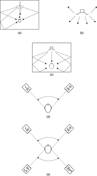
Figure 8.18 (a) Sound approaches microphone from many directions due to ambience and reverberation. (b) In anechoic conditions single loudspeaker produces exactly the opposite of (a). (c) Loudspeaker in reverberant conditions simulates situation of (a) at listener's ears. (d) Stereo systems can only re-create virtual sound sources over angle shown. (e) Surround-sound systems can create further virtual sources to the rear, but not to the side unless additional speakers are used.
However, when listening in a room having a degree of reverberation a better result is achieved irrespective of the reverberation content of the signal. The reverberation in the mono signal has only time delay and no spatial characteristics whatsoever whereas the reverberation in the listening room has true spatial characteristics. The human listener is accustomed to ambient sound approaching from all directions in real life and when this does not happen in a reproduction system the result is unsatisfactory.
Thus in all real listening environments a considerable amount of reverberant sound is required in addition to the direct sound from the loudspeakers. Figure 8.18(c) shows that the reverberation of the listening room results in sound approaching the listener from all sides giving a closer approximation to the situation in (a). Clearly better reverberation will be obtained when the loudspeaker is out in clear space in the room. So-called bookcase loudspeakers mounted on walls or shelves can never give good results.
Better spatial accuracy requires more channels and more loudspeakers. Whilst the ideal requires an infinite number of loudspeakers, it will be seen that, with care, as few as two speakers can give a convincing spatial illusion. The improvement in spatial performance using two speakers is enormous. Tests2 have shown that most people prefer stereo with poor bandwidth and significant distortion to pristine mono. A further improvement can be obtained by using a further pair of speakers to the rear of the listener, with perhaps the addition of a centre speaker between the front ones.
Pairs of speakers can only give spatial accuracy for sound sources located between them. Figure 8.18(d) shows the angle over which stereo speakers deliver an accurate image. Figure 8.18(e) shows that in surround sound there is a further angle to the rear, suggesting that 4/5 channel surround sound is a misnomer as it is no more able to re-create sound sources at the side of the listener than is a stereo system. As a result, reverberation in the listening room must provide ambient sound from all remaining directions.
Clearly the resultant reverberant sound field can never be a replica of that at the microphone, but a plausible substitute is essential for realism and its absence results in an unsatisfactory result. Clearly the traditional use of heavily damped rooms for monitoring is suspect.
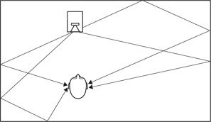
Given a room with reasonable reverberation characteristics, Figure 8.19 shows that the reverberant sound reaching the listener must have been radiated by the loudspeaker in a direction other than on its forwardfacing axis. If realism is to be achieved, the polar diagram of the loudspeaker and its stability with frequency is extremely important. A common shortcoming with most drive units is that output becomes more directional with increasing frequency. Figure 8.20(a) shows that although the frequency response on-axis may be ruler flat giving a good quality direct sound, the frequency response off-axis may be quite badly impaired. In the case of a multiple-drive unit speaker, if the crossover frequencies are too high, each drive unit will have started beaming before it crosses over to the next which widens the directivity again. Figure 8.20(b) shows that the off-axis response is then highly irregular. As the off-axis output excites the essential reverberant field the tonal balance of the reverberation will not match that of the direct sound.3 The skilled listener can determine the crossover frequency, which by definition ought not to be possible in a good loudspeaker.
The resultant conflict between on- and off-axis tonality may only be perceived subconsciously and cause listening fatigue where the initial impression of the loudspeaker is quite good but after a while one starts looking for excuses to stop listening. The hallmark of a good loudspeaker installation is that one can listen to it indefinitely and that of an excellent installation is where one does not want to stop
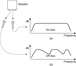
Figure 8.20 (a) Ideal on-axis response is achieved by many loudspeakers. (b) Off-axis response of most loudspeakers is irregular causing colouration of reverberant field.
Unfortunately such instances are rare. More often loudspeakers are used having such poor off-axis frequency response that the only remedy is to make the room highly absorbent so that the off-axis sound never reaches the listener. This has led to the well-established myth that reflections are bad and that extensive treatment to make a room dead is necessary for good monitoring. This approach has no psychoacoustic basis and has simply evolved as a practical way of using loudspeakers having poor directivity. The problem is compounded by the fact that an absorbent room requires more sound power to obtain a given SPL. Consequently heavily treated rooms require high-power loudspeakers which have high distortion and often further sacrifice polar response in order to achieve that high power.
A conventional box-shaped loudspeaker with drive units in the front will suffer extensive shading of the radiation to the rear and thus will create a coloured reverberant field. Clearly a much more effective way of exciting reverberation with an accurate tonal balance is for the loudspeaker to emit sound to the rear as well as to the front. Some surroundsound systems specify such speakers for the rear channels in order to give a better impression of ambience, but the approach is equally valid for the front speakers or for stereo speakers.
Loudspeakers have also been seen with additional drive units facing upwards in order to improve the balance between direct and reverberant sound. These techniques work well but obviously in a dead room are a waste of time as the additional radiation will never reach the listener. The fault is in the room, not the speaker.
8.12 Loudspeaker mechanisms
The two transduction mechanisms used in microphones are both reversible and so can also be applied to loudspeakers. The electrodynamic loudspeaker produces a force by passing current through a magnetic field whereas the electrostatic loudspeaker produces force due to the action of an electric field upon a charge.
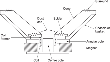
The moving-coil loudspeaker4 is by far the most common device. Figure 8.21 shows the structure of a typical low-cost unit containing an annular ferrite magnet. The magnet produces a radial field in which the coil operates. The coil drives the centre of the diaphragm which is supported by a spider allowing axial but not radial movement. The perimeter of the cone is supported by a flexible surround. The end of the coil is blanked off by a domed dust cap which is acoustically part of the cone. When the cone moves towards the magnet, air under the dust cap and the spider will be compressed and suitable vents must be provided to allow it to escape. If this is not done the air will force its way out at high speed causing turbulence and resulting in noise which is known as chuffing.
A major drawback of the moving-coil loudspeaker is that the drive force is concentrated in one place on the diaphragm whereas the air load is distributed over the surface. This can cause the diaphragm to break up, which is undesirable in a woofer which should act as a rigid piston. Figure 8.22 shows that a more even application of coil thrust can be obtained by using a large coil so that the distance from the point where the drive force is applied is reduced.
The coil in a loudspeaker has appreciable resistance and this results in heating. At high power, the heat can only be dissipated by a large temperature rise. This has the effect of raising the coil resistance, reducing the sensitivity of the speaker. The result is known as thermal compression.
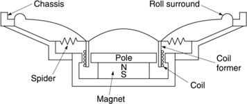
Figure 8.22 Woofer using large coil to distribute force more evenly.
As the density of air is so low, the mass of air a loudspeaker actually moves is a few per cent of the mass of the diaphragm. Consequently most of the drive power supplied to any kind of loudspeaker is wasted in accelerating the diaphragm back and forth and the efficiency is very poor. There is no prospect of this situation ever being resolved in electromagnetic speakers.
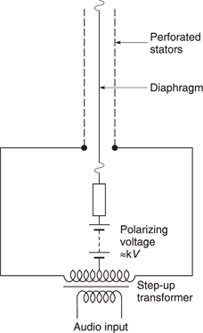
The electrostatic loudspeaker is shown in Figure 8.23. A slightly conductive diaphragm is connected to a high-voltage DC supply so that it becomes charged. The high resistivity of the diaphragm prevents the charge moving around so that at all audio frequencies it can be considered fixed. Any charge placed in an electric field will experience a force. The electric field is provided by electrodes either side of the diaphragm which are driven in antiphase, often by a centre-tapped transformer.
The advantage of the electrostatic loudspeaker is that the driving mechanism is fundamentally linear and the mechanical drive is applied uniformly all over the diaphragm. Consequently there is no reason why the diaphragm should break up. There is no heat-dissipation mechanism in the electrostatic speaker and thermal compression is completely absent. The electrostatic loudspeaker has the further advantage that it is also inherently a dipole, radiating as much sound to the rear as forward.
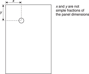
Recently a new type of loudspeaker has emerged which operates on bending waves in a flat panel.5 Figure 8.24 shows that a moving-coil motor is used to excite the panel in a location which is carefully calculated. The panel will break up or resonate, but the correct choice of motor location will ensure that no mode dominates. Such distributedmode loudspeakers (DML) can be very thin, and can also be made transparent so that displays can be seen through them. Radiation takes place from both sides of the panel. This is beneficial in exciting the reverberant field, but for wall mounting a suitable enclosure can absorb the rear radiation. The panel cannot be made to move as a piston and so performance at low frequencies is poor. A crossover to a conventional woofer will be needed if the full frequency range is required.
DML speakers have rather different characteristics from conventional speakers. Their large radiating area means that they do not act as point sources. Their acoustic near-field extends a considerable distance from the panel and in this area the inverse square law does not apply. The frequency response and directivity of correctly designed DML panels are chaotic. At a given listening location the direct sound will have a very irregular frequency response but with no dominant peaks. The reverberant sound will have another irregular frequency response. Masking in the ear results in an average frequency response being perceived and the result can be quite pleasing.
However, DML speakers also have some problems. The distributedmode radiation destroys transient wavefronts and the spatial information they contain (see section 5.11). The lack of a point source means that stereophonic images are smeared. However, the chaotic behaviour and wide directivity makes DML speakers suitable for the rear speakers in surround-sound systems, especially those where radiation from both sides of the panel is allowed. The rear speakers primarily reproduce reverberation and ambience which is inherently chaotic.
The greatest strength of DML speakers is not in competition with conventional speakers. Instead DML should be seen as a technology which allows loudspeakers of reasonable quality to be incorporated into products or locations where the use of a conventional speaker would be impossible.
8.13 Directivity
One of the greatest challenges in a loudspeaker is to make the polar characteristics change smoothly with frequency in order to give an uncoloured reverberant field. Unfortunately crossing over between a number of drive units often does not achieve this. Figure 8.25 shows that at the crossover frequency both drive units separated by a are contributing equally to the radiation. If the wavelength is long compared to the dimensions the system acts as a single driver and the polar diagram will be undisturbed. However, with typical speaker components this will only be true below a few hundred Hz. If a crossover is attempted above that frequency a diffraction pattern will be created where the radiation will sum or cancel according to the path length differences between the two drivers. This results in an irregular polar diagram and some quite undesirable off-axis frequency responses.6
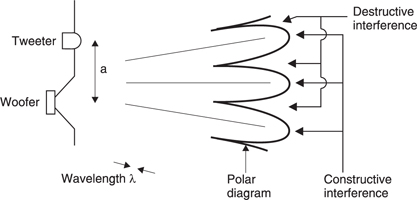
Figure 8.25 At the crossover frequency both drivers are operating and if ka is not small the polar diagram becomes highly irregular because of path-length differences.
Clearly the traditional loudspeaker with many different drive units is flawed. Certain moving-coil and electrostatic transducers can approach the ideal with sufficient care. Figure 8.26(a) shows that if the flare angle of a cone-type moving-coil unit is correct for the material, the forward component of the speed of sound in the cone can be made slightly less than the speed of sound in the air, so that nearly spherical wavefronts can be launched. The cone is acting as a mechanical transmission line for vibrations which start at the coil former and work outwards. This should not be confused with cone break-up which is uncontrolled and detrimental. If frequency-dependent loss is introduced into the transmission line, the higher the frequency, the smaller is the area of the cone which radiates. Done correctly the result is a constant dispersion drive unit. There are vibrations travelling out across the cone surface and the cone surround must act as a matched terminator so that there can be no reflections.
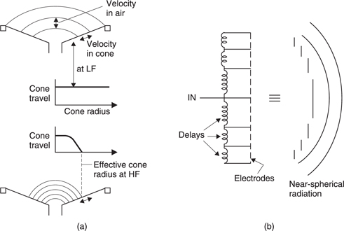
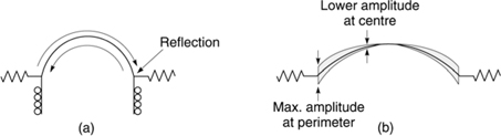
The dome looks as if it ought to have a broad radiation pattern. Unfortunately this simplistic view is quite wrong.1,7 The dome driver exhibits exactly the opposite of what is wanted. In practice domes can't be rigid because vibrations can travel right across the dome and bounce off the other side as shown in Figure 8.27(a). The palliative here is the soft dome which is made from a lossy material. However, with a lossy material, as frequency rises, the centre of the dome decouples and only the perimeter is fully driven, producing an annular radiator of maximum size as shown in Figure 8.27(b). Consequently the polar characteristics of domes are poor and the off-axis response is likely to be impaired. The only advantage of the dome driver is that a very large coil can be fitted which will allow high power dissipation. This allows high SPL to be generated in dead rooms where the poor directivity will be concealed.
The elegant directivity solution in an electrostatic speaker first proposed by Walker of Quad8 is to make the mechanically flat diaphragm behave like a sphere by splitting the electrode structure into concentric rings fed by lossy delay lines as shown in Figure 8.26(b). This produces what is known as a phased array. The outward propagation of vibrations across the diaphragm again simulates quite closely a sector of a pulsating sphere. Matched termination at the perimeter is required to prevent reflections. There is no reason why such an approach should not work with a segmented ribbon speaker.
Using either of these techniques allows the construction of a singledrive unit which will work over the entire mid and treble range and display smooth directivity changes. A low-frequency crossover to a woofer completes the design. Such two-way speakers can display extremely good performance especially if implemented with active techniques.
Interestingly enough if strict polar response and distortion criteria are applied, the phased array electrostatic loudspeaker turns out to be capable of higher SPL than the moving-coil unit. This is because the phased array approach allows the electrostatic loudspeaker to have a very large area diaphragm without beaming taking place. Consequently at mid and high frequencies it can achieve very large volume velocities yet with very small displacements.
8.14 The moving-coil speaker
Unlike the electrostatic speaker, the moving-coil speaker is not fundamentally linear and a number of mechanisms are responsible for less than ideal behaviour. There are two basic criteria for linearity. First, the drive force of the coil should depend only on the current and not on the coil position. Second, the restoring force of the suspension should be exactly proportional to the displacement. Both of these effects are worse at low frequencies where the cone travel is greatest.
Rice and Kellog discovered around 1925 that the displacement of a moving-coil loudspeaker cone reaches a peak at the resonance, and falls at 6 dB per octave either side of that resonance as shown in Figure 8.28(a).
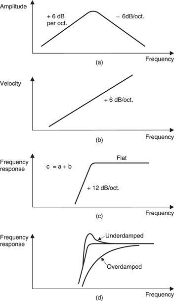
Figure 8.28 (a) The amplitude of a resonant system falls at 6 dB/octave away from the peak. (b) The velocity of the system in (a) is obtained by differentiating the displacement, resulting in a 6 dB/octave tilt. This gives a flat response region with a 12 dB/octave roll-off below resonance. (c) Moving coil motor acts as a transformer coupling resonant system to the coil resistance which acts as a damper. Motor design affects peakiness of resonance (d).
Radiation is proportional to cone velocity which is obtained by differentiating the displacement. Differentiation tilts the response by 6 dB/ octave. Consequently as Figure 8.28(b) shows, the radiation is independent of frequency above resonance but falls at 12 dB/octave below.
Below resonance the motion is stiffness controlled. The displacement is proportional to coil current and velocity leads the current. Above resonance the system is mass controlled. The acceleration is proportional to coil current and velocity lags the current. Figure 8.29 shows the phase response through resonance. Note that at the resonant frequency the velocity is exactly in phase with the coil current. Because of this phase characteristic the polarity of a loudspeaker is a matter of opinion.
Manufacturers mark one terminal with a red spot or a + sign as an aid to wiring in the correct polarity. However, some use the convention that a positive DC voltage (e.g. from a battery) will cause forward motion of the cone, whereas others use the convention that the positive half-cycle of an AC voltage at a frequency above resonance will cause forward motion. It will be seen from Figure 8.29 that these two conventions are, of course, in phase opposition. The AC definition makes more sense as that is how the speaker is used. However, most manufacturers use the DC definition.
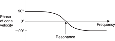
Figure 8.29 Phase response of loudspeaker passes through zero at resonance. The sharper the resonance the more rapid is the phase change.
The phase reversal of a moving-coil driver as it passes through resonance means that it is fundamentally incapable of reproducing the input waveform at frequencies near resonance. Clearly if it is intended to reproduce the input waveform accurately the fundamental resonance must be placed below the audio band at around 20 Hz or signal processing must be used to artificially lower the resonance.
Figure 8.30 shows that with an amplifier of low output resistance, the mechanical resonance is damped by the coil resistance. The moving-coil motor acts as a transformer coupling the resonant system to the damping resistance. Increasing the flux density or the length of coil in the gap increases the effective ratio of the transformer and makes the coil resistance appear lower, increasing the damping. The peakiness of the resonance is adjusted in the design process by balancing the coil resistance, the strength of the magnet and the length of coil wire in the magnetic field. If the drive unit is not driven by a low-output impedance via low-resistance cables the resonance may be underdamped and a pronounced peak may occur.

The moving-coil speaker obtains a drive force due to the coil current reacting against the magnetic field. Figure 8.31 shows that the radial magnetic field is provided by a permanent magnet. If the moving coil motor is to be linear, the force produced must depend only on the current and not on the position. In the case of a tweeter, shown in Figure 8.31(a), the travel is usually so small that the coil can be made the same length as the flux gap as the leakage flux effectively extends the gap. In woofers the travel is significant and in order to obtain linearity the coil can be made shorter (b) or longer (c) than the flux gap. Clearly (c) is less efficient as power is wasted driving current through those parts of the coil which are not in the gap. However, (b) requires a massive magnet structure and is little used because of the weight and cost.
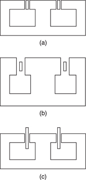
Figure 8.31 (a) Coil same length as gap. (b) Coil shorter than gap. (c) Coil longer than gap.
It is important that the flux distribution is symmetrical. Figure 8.32(a) shows a typical low-cost speaker with casual pole design. Figure 8.32(b) shows a better approach.
The volume of the air gap in which the coil operates is a critical factor. This is given by the gap width multiplied by the gap area. The wider the gap, the greater the magneto-motive force (mmf) needed to drive flux across the gap and the longer the magnet needs to be. The gap width will be set by the radial thickness of the coil plus operating clearances. The gap depth and the pole radius set the pole area and the greater the area over which a given flux density is required, the greater the total flux and the greater the cross sectional area of the magnet will need to be.
The low-cost ferrite magnet is a source of considerable problems in the television environment because it produces so much stray flux. This can cause colour purity errors and distortion of the picture on a CRT because it disturbs the magnetic deflection system. Whilst screening can be installed, a better solution for speakers to be used near CRTs is to employ a different magnetic circuit design as shown in Figure 8.33. Such a design completely contains its own flux because the magnet is inside the magnetic circuit. The magnet has to be smaller, but sufficient flux is easily available using rare-earth magnets. As Figure 8.33(c) shows, the rareearth magnet has a very high energy product and only a small volume of material is required. This can easily be located inside the coil, leading to a very compact motor.
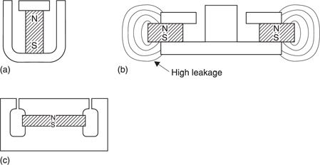
Figure 8.33 (a) Alnico requires columnar magnet. (b) Ferrite requires generous cross-sectional area and leaks badly. (c) Rare-earth magnet has very small volume and mass. Structures (a) and (c) have no external leakage.
As there is no such thing as a magnetic insulator, a good deal of flux is lost to leakage where flux simply jumps from one pole to the next. Undercutting the pole pieces is of some help because it helps to keep as much air as possible in the shunt leakage path. However, the ferrite magnet fares poorly for leakage because its surface area is so large that the shunt reluctance is small. In ferrite designs often only a third of the magnet flux passes through the gap.
The rare-earth magnet can be so small that its shunt reluctance is significantly higher and there is much less leakage. Thus the magnet can be even smaller because the reduced leakage makes it more efficient. Whilst samarium—cobalt rare-earth magnets are expensive, the cost of neodymium-iron-boron magnets is falling and they are starting to become popular in loudspeakers because of their efficiency and low leakage. Rare-earth magnets may have ten times the energy of ferrite, but because the leakage is much reduced it is often possible to use a magnet only one twentieth the volume of a ferrite equivalent. The lower weight allowed by neodymium means that the entire drive unit weighs about one half as much as one having a ferrite magnet.
The coil must have good electrical conductivity and low mass. Most coils are copper, but aluminium has a better conductivity-to-weight ratio. Aluminium wire is available with a thin coating of copper to facilitate making connections. In most cases the coil is made by winding onto a cylindrical former which delivers the coil thrust to the neck of the cone.
The job of the cone is to couple the motion of the coil to a large volume of air. In a woofer the diaphragm is acoustically small and the cone should be rigid so that it acts as a piston. As excessive mass reduces efficiency, the best materials for woofer cones are those which offer the best ratio of modulus of elasticity to density. Other factors include the ability to resist high temperatures reached by the coil former where it joins the neck of the cone, and the inherent damping of the material which prevents resonances.
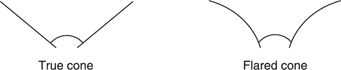
Early cones were made of paper but these are easily damaged and are susceptible to moisture absorption which changes the speaker characteristics as a function of humidity. The conical shape was adopted because it allows a great increase in stiffness over a flat sheet of material. Even greater stiffness is possible if the cone is flared as shown in Figure 8.34.
Many different approaches have been tried for cone construction and in woofers at least, many of these have been successful. Figure 8.35 shows some possibilities for woofers. The sandwich construction uses two skins, typically of aluminium, with a low-density core, typically of expanded polystyrene. This is sometimes taken to the extreme case where the cone is solid, having a flat front. Aluminium cones can be turned into sandwich structures by anodizing. The hard oxide layer due to the anodizing step forms a rigid skin and the aluminium forms the core. Thermoplastics have been used for cones and have the advantage that they can be moulded at low cost, but are unsuitable for high-power applications. Recently composite materials have become economic and their high stiffness-to-density ratio which makes them attractive in aerospace is equally useful in loudspeakers.
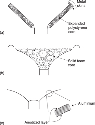
Figure 8.35 (a) Sandwich woofer cone. (b) Solid foam woofer diaphragm. (c) Anodized aluminium forms a sandwich.
In tweeters the cone design is more difficult because of the need to allow the cone to act as a transmission line without allowing uncontrolled break-up. This makes the stiffness and damping critical. In many cases one single material is unsuitable and the cone is made from a suitably stiff material which has an appropriate internal speed of sound and a separate damping layer may then be provided.
8.15 Low-frequency reproduction
An unenclosed diaphragm acts as a dipole and these become extremely inefficient at low frequencies because air simply moves from the front to the back, short-circuiting the radiation. In practice the radiation from the two sides of the diaphragm must be kept separate to create an efficient LF radiator. The concept of the infinite baffle is one in which the drive unit is mounted in an aperture in an endless plate. Such a device cannot be made and in practice the infinite baffle is folded round to make an enclosure. Sealed enclosures are often and erroneously called infinite baffles, but they do not have the same result. Unfortunately the enclosed air acts as a spring because inward movement of the diaphragm reduces the volume, raising the pressure.
The stiffness of this air spring acts in parallel with the stiffness of the diaphragm supports. The mass of the diaphragm and the total stiffness determines the frequency of fundamental resonance of the loudspeaker. To obtain reproduction of lowest frequencies, the resonance must be kept low and this implies a large box to reduce the stiffness of the air spring, and a high-compliance drive unit. When the air stiffness dominates the drive unit stiffness, the configuration is called acoustic suspension.
Acoustic suspension speakers were claimed to offer a more accurate compliance than the speaker's mechanical flexure, but this is not true.
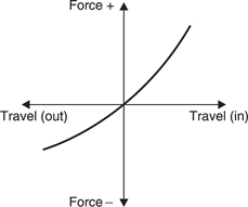
Figure 8.36 An air spring is non-linear producing more restoring force on compression than on rarefaction.
The air spring in a sealed box is fundamentally non-linear. This is easy to see by considering Figure 8.36. Here a diaphragm will displace a volume equal to the volume of the box. If the diaphragm moves inwards, the pressure becomes infinite. If the diaphragm moves outwards, the pressure is merely halved. It is simple to calculate the distortion given the diaphragm displacement and the box volume.
In early attempts to give satisfactory low-frequency performance from smaller boxes, a number of passive schemes have been tried. These include the reflex cabinet shown in Figure 8.37(a) which has a port containing an air mass. This is designed to resonate with the air spring at a frequency below that of the fundamental resonance of the driver so that as the driver response falls off the port output takes over. In some designs the air mass is replaced by a compliantly mounted diaphragm having no coil, known as an ABR or auxiliary bass radiator, (b).
Another alternative is the transmission line speaker shown in (c) in which the rear wave from the driver is passed down a long damped labyrinth which emerges at a port. The length is designed to introduce a 180° phase shift at the frequency where the port output is meant to augment the driver output. A true transmission line loudspeaker is quite large in order to make the labyrinth long enough. Some smaller models are available which claim to work on the transmission line principle but in fact the labyrinth is far too short and there is a chamber behind the drive unit which makes these heavily damped reflex cabinets.
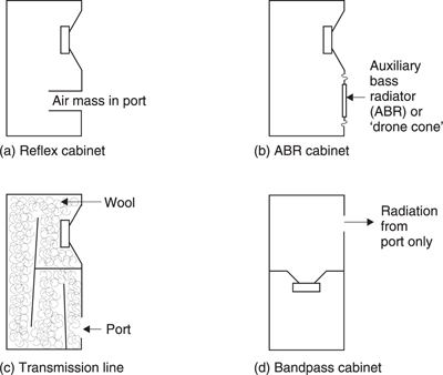
Figure 8.37 Various attempts to reproduce low frequencies. (a) Mass of air in reflex duct resonates with air spring in box. (b) Air mass replaced by undriven diaphragm or ABR. (c) Rear wave is phase shifted 180° in transmission line to augment front radiation. (d) Bandpass enclosure puts drive unit between two resonating chambers. None of these techniques can properly reproduce transients and active techniques have rendered them obsolete.
More recently the bandpass enclosure (d) has become popular, probably because suitable computer programs are now available to assist the otherwise difficult design calculations. The bandpass enclosure has two chambers with the drive unit between them. All radiation is via the port.
The reflex, ABR, bandpass and transmission line principles have numerous drawbacks, the most serious of which are that the principle only works on continuous tone. Low-frequency transients suffer badly from linear distortion because the leading edge of the transients are removed and reproduced after the signal has finished to give the phenomenon of hangover. The low-frequency content of the sound lags behind the high frequencies in an unnatural way. In other words the input waveform is simply not reproduced by these tricks as is easily revealed by comparison with the original sound.
Different order filtering and different damping change the amount by which this lag takes place, but can never eliminate the problem, which is most noticeable on transient musical information such as percussion and on effects such as door slams. It is quite impossible to use such a lowfrequency technique in conjunction with a linear phase electrostatic highfrequency unit or a constant directivity mid-top moving-coil unit because the quality mismatch is too obvious.
The only low-frequency structure which can approach the reproduction of the input waveform is the sealed box. In passive loudspeakers, in order to reproduce the lowest frequencies the box will need to be large to prevent the stiffness of the air spring raising the fundamental resonance. Unfortunately a large box forms a very poor place from which to radiate high frequencies. Figure 8.38 shows that when a high-frequency unit is fitted in a large box, diffraction results in reradiation at the corners.9,10
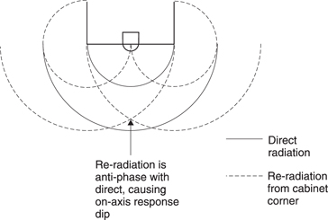
Figure 8.38 Attempting to radiate high frequency from a tweeter mounted in a large rectangular box produces frequency response irregularity due to diffraction from the box corners.
When the direct and reradiated sounds combine the result is constructive or destructive interference depending on the frequency. This causes ripples in the on-axis frequency response. The larger the box, the further down the spectrum these ripples go. The effect can be reduced by making the cabinet smaller and curved with no sharp corners.
8.16 Crossover networks
As the full-range drive unit is virtually impossible, practical loudspeakers need to employ several drive units, each optimized for a particular frequency range. A crossover network is needed so that signals of the right frequency are sent to the appropriate drive unit. Perhaps it is more accurate to say that the wrong frequencies are prevented from reaching drive units which cannot handle them.
Loudspeakers are highly traditional devices which continue to be built in the same way even though the restrictions which originally led to the approach have long since disappeared. At one time audio amplifiers were expensive and the multi-drive unit loudspeaker had to use a single amplifier to control cost. This meant that the crossover had to be performed at power level. Figure 8.39(a) shows a typical simple power level crossover. An inductor in series with the woofer reduces the input at high frequencies as its impedance rises whereas a capacitor in series with the tweeter increases the input at high frequencies as its impedance falls. The crossover slope is only 6 dB per octave which means that the two drive units will still receive significant signal levels outside their operating bandwidth. A steeper crossover can be obtained by using a second-order filter (b) which achieves 12 dB/octave.
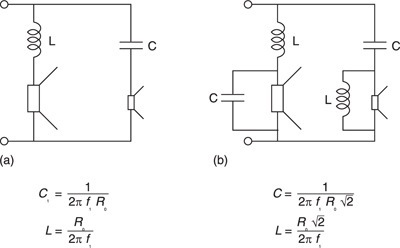
Figure 8.39 (a) Simple 6 dB/octave crossover. (b) 12 dB/octave requires second-order filter.
Unfortunately none of these simple approaches work properly. It is self-evident that the sum of the two crossover outputs ought to be the original signal. This is known as a constant voltage crossover.11 However, passive crossover techniques simply cannot reach this goal and must be considered obsolete for high-quality applications.
Using analog computing techniques it is easy to create constant-voltage crossovers. A filter is used to prevent unwanted frequencies reaching a certain drive unit. If the output of that filter is subtracted from the input, as in Figure 8.40, the result is the frequencies which the drive unit can handle. By definition, the sum of the two signals is the original. With more complexity, such a crossover can be made symmetrical or asymmetrical and have slopes to suit the characteristics of the drive units. When properly engineered the crossover frequency simply cannot be determined by listening.
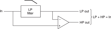
Figure 8.40 Active crossover with constant voltage characteristic gives precision that is impossible with passive crossovers.
8.17 Enclosures
The loudspeaker enclosure has to fulfil two functions. At low frequencies it must contain the back radiation from the woofer and at high frequencies its shape determines the diffraction characteristics which will affect the on-axis frequency response and the directivity.
At low frequencies an enclosure must be rigid so that internal pressures do not cause flexing. As the area of the enclosure walls is an order of magnitude greater than the woofer cone area, the slightest flexing can cause appreciable colouration of the sound. In other industries vessels to contain or resist pressure are invariably cylindrical or spherical. The aerosol can, the airliner and the submarine are good examples. The dogged adherence to the square box made from six flat panels illustrates that even today most loudspeakers are designed by tradition rather than physics.
At high frequencies the sharp corners on a square loudspeaker cause impedance changes and act as secondary radiators. This is also true of the woofer if this is exposed.10 Many years ago Olsen9 produced his definitive series of tests on speaker enclosure shapes, but this has been largely ignored.
Fortunately a small number of manufacturers are making loudspeakers in enclosures which rely on curvature for both stiffness and diffraction control. These are not necessarily expensive to make using moulding techniques, but the result is much less colouration of the sound and an opportunity for a more interesting visual appearance.
8.18 Active loudspeakers
With modern electronic techniques all passive schemes with their inevitable compromises and shortcomings must be considered obsolete. The traditional wideband power amplifier having low distortion and a flat frequency response which expects to see a loudspeaker with the same characteristics is both overly optimistic and an unnecessary restriction. What is required is a system whereby the radiated sound resembles the original line level signal. What goes on inside the box to achieve this is the designer's problem.
An active loudspeaker containing its own amplifiers can easily introduce equalization and signal processing which can artificially move the fundamental resonance down in frequency and achieve any desired damping factor. The crossover can be performed precisely and at low cost at line level instead of imprecisely at power level using large expensive components. Inverse distortion can be applied to compensate for drive unit deficiencies. The advantage of this approach is that the speaker can be made relatively phase-linear and will not suffer from hangover. The smaller cabinet also allows the radiation characteristics of the mid and high frequencies to be improved. The sensitivities of the drive units do not need to be matched so that there is more freedom in their design. In the absence of separate amplifier cabinets less space is needed overall and the dubious merits of exotic speaker cables become irrelevant.
Figure 8.41 shows the block diagram of a modern active loudspeaker. The line-level input passes to a crossover filter which routes low and high frequencies to each driver. Each drive unit has its own power amplifier. The low-frequency power amplifier is preceded by a compensation network which can electronically lower the resonance of the low-frequency driver and determine the damping factor. In some units the low-frequency diaphragm is fitted with a feedback transducer so that distortion can be further reduced.
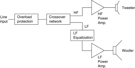
Electronic compensation of the fundamental resonance of a woofer makes it possible to reduce the size of the enclosure dramatically. Techniques of this kind allow realistic reproduction of low frequencies from enclosures whose volume would have been considered impossible a few years ago. If the goal is to add loudspeakers to a plasma display, only a very small enclosure is available and passive loudspeakers simply cannot function adequately.
8.19 Loudspeaker criteria for stereo and surround sound
The accuracy required for spatial reproduction is much greater than for mono. Spatial reproduction includes conventional stereo with two speakers and the frontal image creation in a surround-sound system having a centre speaker in addition to the left and right speakers since the physics is the same in both cases. If there is any non-linearity in the system, different sound sources will intermodulate and produce phantom sound sources which appear to come from elsewhere in the image than either of the original sounds. As these phantom sources are spatially separate from the genuine sources, they are easier to detect.
Where non-ideal speakers are used, it is important that the two speakers are absolutely identical. If the frequency and phase responses are not identical, the location of the apparent sound source will move with frequency. Where a harmonically rich source is involved, it will appear to be wider than it really is. This is known as smear.
If the loudspeakers suffer from beaming at high frequency then a proper image will only be obtained at a small ‘sweet spot’ and all high frequencies will appear to emanate from the speakers, not from a central image. Small movements by the listener may cause quite large image changes. Irregular polar diagrams will also destroy stereo imaging. Such irregularities often occur near the crossover frequencies. Placing the drive units in a vertical line will prevent the horizontal polar diagram becoming too irregular. However, this idea is completely destroyed if such a speaker is placed on its side; a technique which is seen with depressing regularity. This may be because many loudspeakes are so mediocre that turning them on their side does not make them sound any worse.
Loudspeakers and amplifiers used for stereo or surround-sound production must have very low distortion and a precisely tracking frequency and phase response. Loudspeakers must have smoothly changing directivity characteristics. In practice a great deal of equipment fails to meet these criteria.
In many audio/visual applications the level of background noise is high and/or the room acoustic is deficient, making conventional monitoring difficult. In many cases there is little space left for loudspeakers once all the video equipment is installed. One solution is the close-field monitor which is designed and equalized so that the listener can approach very close to it. The term ‘near-field’ is often and erroneously used to describe close-field monitors. The essence of closefield monitoring is that direct sound reaches the listener so much earlier than the reverberant sound that the room acoustic becomes less important. In stereo close-field monitoring the loudspeakers are much closer together, even though the same angle is subtended to the listener.
References
1. Watkinson, J.R., Transducer drive mechanisms, in Borwick, J. (ed.), Loudspeaker and Headphone Handbook, 3rd edn, Ch.2: Oxford: Focal Press (2000)
2. Olson, H.F., Stereophonic sound reproduction in the home. J. Audio Eng. Soc., 6, No.2, 80–90 (1958)
3. Moir, J., Speaker directivity and sound quality. Wireless World, 85, No. 1526 (Oct. 1979)
4. Rice, C.W. and Kellog, E.W., Notes on the development of a new type of hornless loudspeaker. JAIEE, 12, 461–480 (1925)
5. Azima, H., Colloms, M. and Harris, N., Acoustic device. EP 0 847 661 B1 (1999)
6. Shorter, D.E.L., A survey of performance criteria and design considerations for highquality monitoring loudspeakers. Proc. IEE, 105, Part B, No.24, 607–623 (Nov. 1958)
7. Kates, J.M., Radiation from a dome, in AES Anthology: Loudspeakers, Vol.1-Vol.25, New York: Audio Engineering Society (1978)
8. Walker, P.J., New developments in electrostatic loudspeakers. J. Audio Eng. Soc., 28, No.11, 795–799 (Nov.1980)
9. Olson, H.F., Acoustical Engineering, Philadelphia: Professional Audio Journals Inc. (1991)
10. Kates, J.M., Loudspeaker cabinet reflection effects. J. Audio Eng. Soc., 27, No. 5 (1979)