
Chapter 9
Anti‐solvent Crystallization
Addition of an anti‐solvent is potentially the most common method to achieve controlled and scalable particle size distribution (PSD). The addition can be either semi‐batch—anti‐solvent added to product solution or product solution added to anti‐solvent (reverse addition)—or continuous using an in‐line mixer or stirred vessel. Of these, the in‐line mixer offers in some cases the highest potential for predictable results, as will be discussed below.
The obvious disadvantage of the anti‐solvent process is the necessity to introduce an additional solvent or solvents, thereby reducing the volumetric productivity and creating a solvent mixture requiring some form of purification/separation for downstream processing and/or recovery.
9.1 OPERATION
9.1.1 Normal Mode of Addition
The addition of an anti‐solvent can be carried out in different ways, as indicated in Figure 9.1, where the concentration of product is shown on the ordinate and the amount of anti‐solvent added is shown on the abscissa. A typical equilibrium solubility curve is indicated as A–B–C (This curve could be concave or linear but is shown as convex for clarity). The metastable region is indicated as the area between B–C and E–D. From point A to point B, addition of anti‐solvent will proceed without crystallization because the solution concentration is below the equilibrium solubility. At point B, equilibrium solubility is reached. As the addition of anti‐solvent continues, supersaturation will develop. The amount of supersaturation that can be developed without nucleation is system specific and will depend on the addition rate, mixing, primary and/or secondary nucleation rate, and growth rate, as well as the amount and type of impurities present in solution.
If growth‐dominated crystallization is desired, with the presence of a sufficient quantity of seed and a sufficiently slow addition rate, the concentration in solution may remain completely in the metastable region as crystallization proceeds. The closer the solution concentration profile is to the equilibrium solubility curve (B–C), the higher the possibility of achieving an all‐growth process.
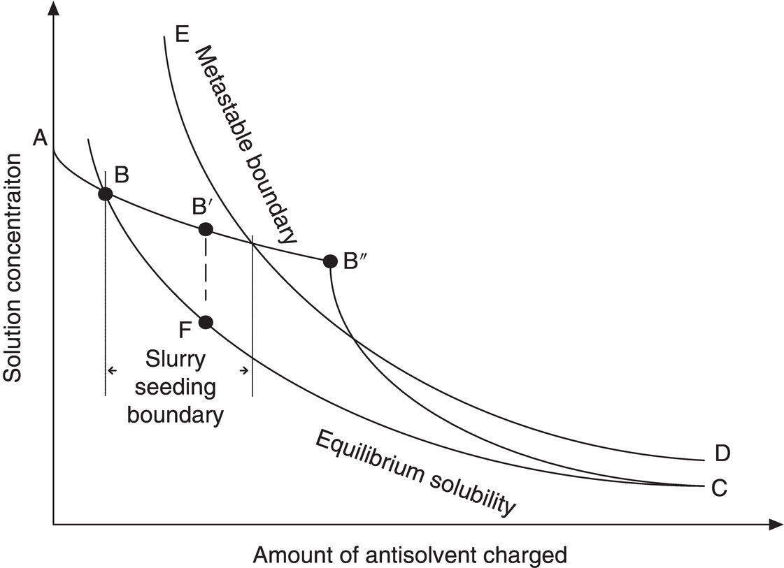
Figure 9.1 Concentration profiles for normal addition of anti‐solvent to batch solution with reference to equilibrium saturation and the metastable zone.
On the other hand, a system without seed or a high addition rate can develop a high degree of supersaturation, which can result in rapid precipitation or crash‐out at point B″, beyond the metastable zone. Crash‐out could be followed by continued nucleation and some growth (B″–C), and eventually to equilibrium at some time after all the anti‐solvent is added. When the concentration is allowed to go to point B″, the system is also subject to oiling out and/or agglomeration, as discussed in Section 9.1.2.
A common practical approach to achieving growth while minimizing concern for seed dissolution is shown in curve B′–F–C. The addition of anti‐solvent is stopped, and seed is added at point B′, where the system is slightly supersaturated. As discussed in Chapter 2, in‐line measurement by Fourier transform infrared (FTIR) or ultraviolet (UV) can be utilized to determine when the concentration reaches point B′. Alternatively, the seed may be added in a slurry with the anti‐solvent starting before point B is reached, as discussed in Chapter 6 and below in Section 9.1.4.
Crystallization is then allowed to proceed to relieve the supersaturation without the addition of more anti‐solvent (B′–F). Given sufficient time, point F could closely approach the equilibrium solubility value while developing sufficient surface area to achieve essentially all growth when addition of anti‐solvent is resumed. Given this increased surface area and a sufficiently slow addition rate, the solution concentration can approach the equilibrium solubility for the remainder of the addition (F–C).
9.1.2 Reverse Addition
In the event that fine particles are desired, the order of addition can be reversed and the product solution added to the anti‐solvent. This method is shown in Figure 9.2. The solubility in the anti‐solvent is very low at point A. Because of the low solubility, the supersaturation ratio will increase rapidly (E–F) before there is sufficient seed area to achieve any significant growth. If the addition is fast enough, growth can be eliminated, resulting in all nucleation and creation of very fine particles. Even with slower addition and seed initially present, the low equilibrium solubility can create high supersaturation ratios throughout the addition and result in the generation of small particles.
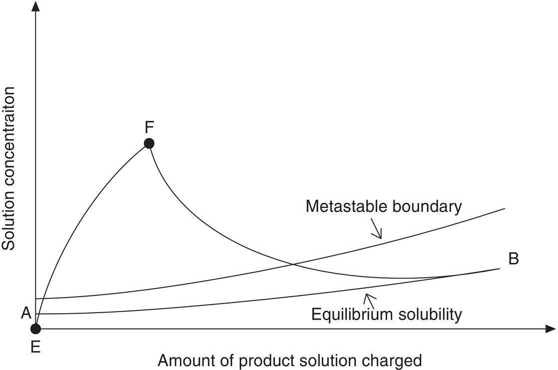
Figure 9.2 Concentration profile for reverse addition (solute solution to antisolvent) with reference to equilibrium saturation and the metastable zone.
A potential complication for all crystallization methods, and particularly for this type of addition, is the tendency for organic compounds to oil out and/or agglomerate as fine particles into amorphous, undefined structures (see Chapter 6). One possible cause of oiling out is that drops of the product solution are surrounded by the antisolvent, in which the solubility is very low, and this low solubility creates localized regions with very high supersaturation ratios. Before mixing to the molecular level is achieved, the localized high supersaturation forces the product out of solution without allowing sufficient time for the ordering of molecules to allow crystal development. The resulting oil particles have a tendency to clump together before the occluded solvent is dispersed throughout the bulk. As the mixture is aged, the oiled‐out particles may transform into amorphous solids or become crystalline. Crystals developed in this manner will likely have a poorly defined structure. The problems that may result from such a scenario may include
- large drops of coalesced oil that will not disperse and can harden into a gum
- severe mixing issues due to the size and physical characteristics of the gum
- occlusion of impurities and solvent in the gum
The other potential issue is that the fine particles can stick together. The resulting agglomerates may be either strong enough to remain as agglomerates or weakly structured and reduce in size with continued mixing and/or subsequent processing (e.g. pump transfer). For a discussion of agglomeration, see Mersmann (2001), Sohnel and Garside (1992), and Chapter 6 in this book.
The above discussion of the potential negative effects from reverse addition (oiling out, poor crystal form, and agglomeration) is necessarily qualitative, since this procedure, more so than many others, is strongly system dependent. The results could be satisfactory or unacceptable, depending on process requirements. Scale‐up of reverse addition is particularly difficult because of the large deviations from equilibrium that are implicit in its implementation.
9.1.3 Simultaneous Mode of Addition
In this mode of operation, both the batch and antisolvent streams can also be charged simultaneously to the crystallizer. The solvent composition will jump directly to the selected point without going through the intermediate solvent composition, so the solvent composition remains unchanged through the main course of crystallization.
One unique feature of simultaneous mode addition is control of crystal form. Since it can target specific solvent composition (and temperature), it can target specific crystal form at that solvent composition (and temperature). This approach can be useful for drugs which have complex crystal form landscape at different solvents/mixture. For example, at low water content, the anhydrate is the stable form. But at high water content, it converts to hydrate, etc.
For simultaneously addition, similar to the nominal or reverse mode of addition, the addition rate will affect the degree of supersaturation. Fast addition rate will generate high supersaturation. This maybe desirable for nucleation‐dominant operation, for example impinging jet or in situ wet seed generation. Certainly, faster addition rate will carry the probability of formation of oil, amorphous solids, and metastable crystal forms as well. Slow addition rate will generate low supersaturation and will be applied for growth dominant operation, which likely covers the majority of the cases
9.1.4 Addition Strategy
A common addition strategy is linear addition of the antisolvent. This addition strategy results in variable supersaturation as addition proceeds. As shown in Figures 9.3 and 9.4 (curve A in both figures), supersaturation generally increases rapidly upon the addition of antisolvent at a constant rate. If the metastable region is as indicated, the supersaturation will exceed the limit very rapidly at the early phase of addition, and a nucleation‐dominated process could result.
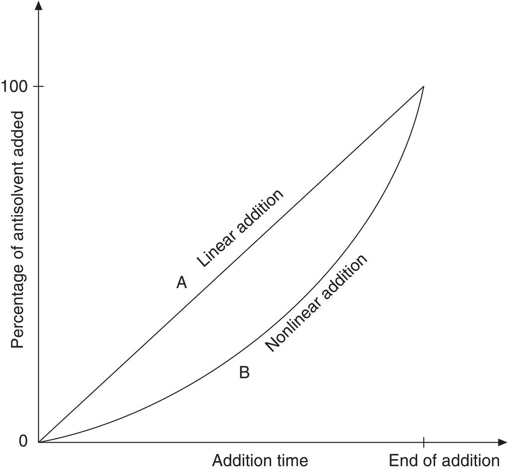
Figure 9.3 Addition rate profile for linear (curve A) and programmed (curve B) antisolvent addition rates.

Figure 9.4 Solubility and supersaturation profiles for the linear and optimum addition rates.
As shown in Figures 9.3 and 9.4, curve B, the addition rate, can be slow initially and gradually increased to achieve a relatively constant level of supersaturation. The rate could follow a slowly increasing rate of addition, an analogy to the strategy of a programmed rate of temperature drop as originally proposed by Griffiths (1925) and further developed by Nyvlt (1971, pp. 118ff.). Other discussions of this control strategy may be found in Jones and Mullin (1974) and Myerson (2002, pp. 223ff.). In an ideal balanced situation with constant supersaturation and constant release of supersaturation via crystal growth and/or nucleation, the solution concentration profile will be maintained close to the solubility curve, as shown in Figure 9.4 for programmed addition. This addition strategy has the potential to minimize nucleation and achieve growth by keeping the solution concentration within the metastable region. Growth potential is further enhanced by seeding, as discussed below.
For the case of in situ wet seed generation approach, the addition strategy can be slightly modified. At the stage of generating the in situ seed, the addition can be rapid or spike‐charge. It can generate seed under high supersaturation with a proper mixer. After aging and letting the seed bed to release the supersaturation, the addition rate for the remaining crystallization process can follow the similar strategy to maximize crystal growth and minimize nucleation.
9.1.5 Seeding
Seeding is addressed throughout this book, and many of the issues apply to antisolvent addition. The primary issues of seeding point, seed size, and amount are again critical to avoid excessive nucleation. The seed can be added as a powder, as a slurry in the antisolvent, or generated in situ with wet milling. The latter two approaches are preferred for many reasons, including ease of handling and satisfaction of containment requirements, as well as a possible increase in the effectiveness of the seed surfaces by “seed conditioning” in the antisolvent slurry to dissolve or remove shards.
Antisolvent addition strategies provide an alternative to the common method of addition of seed as a “shot.” The shot method is subject to variable results because the seed may be subject to total dissolution if added too soon (before reaching point B, Figure 9.1), or it may be ineffective in preventing excessive nucleation if added too late (after point B).
Since the seed is by definition not significantly soluble in the antisolvent, a slurry can be prepared of the seed in a small quantity (~5–10%) of the antisolvent, and this slurry is added to the substrate solution to achieve initial supersaturation. The timing of this addition is not as critical as that for adding a shot of seed, since it can be started near the saturation point and continued until the overall concentration is in the metastable region. The antisolvent in this slurry provides the driving force to reduce solubility and ultimately to reach saturation. Enough seed must be used since some of it will dissolve if the addition is started before the saturation point is reached. The difficulty is determining exactly where this point is from batch to batch, thereby presenting the same issue discussed for cooling and evaporative crystallization (Chapters 7 and 8, respectively). As in those cases, online analytical methods can be used to alleviate or remove this uncertainty. When these methods are difficult or impractical, the antisolvent slurry‐seeding technique can be effective, and it has been successfully employed in several difficult situations.
For in situ wet seed generation approach, the amount of seed could be from points B′–F in forward addition mode as shown Figure 9.1. If batch and antisolvent are charged simultaneously, the amount of in situ wet seed can be determined by the portion of the batch charged initially at the seed generation stage. A rule of thumb for the in situ seed generation can be ~20%. The size of seed can also be turned by applying different types of wet mills, operating conditions such as temperature or composition. Examples in this chapter and Chapter 13 will illustrate various scenarios of simultaneous addition and in situ seed generation with wet milling.
9.2 IN‐LINE MIXING CRYSTALLIZATION
The focus of this book is on controlling crystallization processes at low supersaturation in order to minimize nucleation and thus promote conditions for growth. These processes are carried out primarily in stirred vessels, although in several examples fluidized beds are utilized. For some applications, i.e. pharmaceutical bulk products with low aqueous solubility, small mean particle size (3–5 μm or less and narrow PSD) are required for enhanced bioavailability or for inhalation therapy. In some cases, these particle sizes can be achieved by appropriate milling devices. However, milling can be undesirable because of environmental concerns about therapeutically active fine dusts. Installation and maintenance of the necessary engineering control and containment may be costly. In addition, milling can induce stresses and surface qualities such as electrostatic charges.
Development work for rapid mixing of reagents for fast chemical reactions has resulted in improved methods of contact. The preferred reactor design for extremely fast or mixing sensitive reactions is an in‐line mixer of appropriate design. Various possibilities have been investigated including centrifugal pumps (Bolzern and Bourne 1985); rotor–stator Mixers (Bourne and Garcia‐Rosas 1986); impinging thin liquid sheets (Demyanovich and Bourne 1989); impinging jet mixing for reaction injection molding (Edwards 1984); and vortex mixing (Johnson 2003).
For crystallization, the objective of an in‐line mixing device would be to mix the product solution and antisolvent to the molecular level in less than the induction time for nucleation. The impinging jet and vortex mixer designs can achieve these high degrees of micromixing at significant scale in an economical manner.
For impinging jet crystallization, industrial operation is described by Midler et al. (1994), with variants by Lindrud et al. (2001) (impinging jet crystallization with sonication) and by Am Ende et al. (2003) (specific reference to reactive crystallization). Laboratory studies are reported by Mahajan and Kirwan (1996), Benet et al. (1999), Condon (2001), and Hacherl (Condon 2003). Johnson (2003) and Johnson and Prud’homme (2003) report on the use of impinging jets to produce nanoparticles stabilized by block copolymers.
The local energy dissipation rate for an impinging jet can be several order higher than that of a stirred vessel (see Paul et al. 2003, chapter 13, and table 5.2). Impinging jet crystallization technology generates very high local supersaturation in order to create many fine nuclei. This process operates at concentrations—induced by antisolvent in the opposing jet—that are above the metastable upper limit, thereby inducing nucleation. Operation under this condition is feasible because control of nucleation can be achieved in a small, intensely mixed volume. This degree of control of nucleation is very difficult to achieve in a stirred vessel, despite application of current knowledge regarding localized distribution of energy dissipation.
Scale‐up of an impinging jet process is simplified because the laboratory/pilot‐scale feed line diameters may require only a two‐ or fourfold scale‐up. The primary increase in scale is achieved by a longer run time. However, since the mixing device produces the same conditions of supersaturation at all times during operation, the time of the run can be increased manifold without changing the nucleation conditions.
The small particle sizes that can be achieved by this technology can result in downstream operation issues with filtration rate, washing, and drying. These issues may be partially offset by the characteristic narrow PSD that can be effective in increasing the filtration rate. These issues must be considered in an overall assessment of the use of this technology compared to the potential advantage of eliminating milling (other than delumping).