CASE STUDY 1
Case Study – LTE Baseband Software Design
Introduction
Wireless communications technology has grown tremendously in the past few years. The first generation (1G) analog cellular systems like Advanced Mobile Phone Systems (AMPS), Total Access Communication Systems (TACS) etc. supported only voice communication with some roaming limitations. The second generation (2G) digital cellular systems promised higher capacity, national and international roaming and better speech quality than analog cellular systems with Enhanced Full Rate (EFR) and Adaptive Multi-Rate (AMR) codec. The two popularly deployed second generation (2G) cellular systems are GSM (Groupe Special Mobile later commonly known as Global System for Mobile communications) and CDMA (Code Division Multiple Access). The 2G systems were primarily designed to support voice communication while lower data rate of up to 14.4 kbps data transmission were introduced in the later releases of 2G standards.
The International Telecommunication Union (ITU) initiated IMT-2000 (International Mobile Telecommunications-2000) paved the way for 3G. A set of requirements such as a peak data rate of 2 Mbps and support for vehicular mobility was published under IMT-2000 initiative. The GSM migrations are based on 3rd generation partnership project (3GPP) and CDMA migrations are based on 3GPP2.
High-data-rate, low-latency and packet-optimized radio access technology supporting flexible bandwidth deployments beyond 3G technologies are the main goals of LTE.
A new network architecture is designed with a goal to support packet-switched traffic with seamless mobility, quality of service and minimal latency. The air-interface related attributes of the LTE system are summarized in Table 1.
Table 1: LTE features.
| Bandwidth | 1.25 – 20 MHz |
| Duplexing | FDD, TDD, half duplex FDD |
| Mobility | 350 Km/h |
| Multiple access | Downlink: OFDMA Uplink: SC-FDMA |
| MIMO | Downlink – 2 Uplink – 1 |
| Peak data rate in 20 MHz | Downlink – 173 Mbps with 2 Uplink – 86 Mbps with 1 |
| Modulation | QPSK, 16-QAM, 64-QAM |
| Channel coding | Turbo code |
| Other techniques | Link adaptation, Channel sensitive scheduling, Power control, Hybrid ARQ |
LTE architecture
LTE has been designed to support only packet-switched services, in contrast to the circuit-switched model of previous cellular systems. It aims to provide seamless Internet Protocol (IP) connectivity between User Equipment (UE) and the Packet Data Network (PDN), without any disruption to the end users’ applications during mobility. While the term ‘LTE’ encompasses the evolution of the radio access through the Evolved-UTRAN (E-UTRAN), it is accompanied by an evolution of the non-radio aspects under the term ‘System Architecture Evolution’ (SAE) which includes the Evolved Packet Core (EPC) network. Together LTE and SAE comprise the Evolved Packet System (EPS). EPS uses the concept of EPS bearers to route IP traffic from a gateway in the PDN to the UE. A bearer is an IP packet flow with a defined Quality of Service (QoS) between the gateway and the UE. The E-UTRAN and EPC together setup and release bearers as required by applications.
It consists of several different types of nodes, some of which are briefly illustrated in Figure 1. The eNodeB is connected to the EPC by means of the S1 interface, more specifically to the S-GW by means of the S1 user-plane part, S1-u, and to the MME by means of the S1 control-plane part, S1-MME. One eNodeB can be connected to multiple MMEs/S-GWs for the purpose of load sharing and redundancy.

Figure 1: LTE architecture
Evolved system components and design
As the complexity and real time processing requirements of the system have grown over a period of time, the components of the LTE system have also evolved simultaneously. A discussion regarding the prime components and associated design considerations is followed here.
Multi-core digital signal processors
While clock speeds can only be increased to a certain point, multi-core processors have become preferred choice for implementation of complex software like LTE physical layer. In order for the applications to make the most of the evolving multi-core architectures, they must be designed from the beginning with multithreading in mind that allows an application to separate itself in many smaller tasks that can be run on different cores at the same time.
Challenges in multi-core design
Deadlock prevention and data protection
Use Case 1: System initialization
In a multi-core environment, when data is kept in a shared memory that is designed to be used by different processes on different cores then this data needs protection to ensure data integrity. This can be achieved through an effective implementation of locks.
It is also, sometimes, essential to ensure the synchronization in time when one process inherently assumes the completion of the work being done by another process. This can be achieved through usage of barriers.
Barriers are an extremely useful mechanism for regulating program execution, especially when multiple cores have to be brought to a common point of execution. These can be implemented with different scope. Centralized barrier ensure that all the cores come to the single point of execution while partial barrier ensure that only some cores are programmed to come to a common control function or label before execution can continue.
In a classical software design on a multi-core platform, the system initialization is undertaken by one core. This ensures centralized ‘record keeping of initialization activities’ and an ease of debugging. An example of a key system initialization task is the initialization of the task inventory structure that defines the various tasks existing in the system. Every task when it is created, dynamically or statically, is required to register itself with the system along with the associated handler function with the help of the task inventory structure. This structure, hence, maintains an inventory of various tasks in the system. This structure has to be available in shared memory to enable any core to trigger a task on itself or another core. In a multi-core system, different cores can come out of the reset at different times. In such a case, it is possible that even before the task inventory structure is initialized by the core assigned to perform the structure initialization, another core which has come out of the reset early has registered a new task with the system using this task inventory structure.
This design problem can be resolved by using the barrier capability, which will force all the cores to come synchronize at a common point of execution. After this synchronization point is reached, the structure will be initialized by the core assigned to do that task. Only after this step is complete, further execution by individual cores will continue. The initialization using barrier synchronization is illustrated in Figure 2.

Figure 2: Initialization and synchronization using barrier.
A key method of data protection in software is the usage of locks. Using locks, the software designer can share the same resource across different processes effectively. This can be achieved through spinlocks where each core keeps on checking on the availability of the resource. An alternative implementation method is through the usage of semaphore logic, where the task goes into a queue if the resource is not available.
Inter-core communication
Use Case 2: Triggering of sequential and parallel processes
Software design on multi-core requires an efficient mechanism for inter-core communication. This communication mechanism should ensure that a process running on one core can trigger another task on the same core or a different core. Two types of inter-core communication mechanism are generally necessary: point to point transfer of messages and point to multipoint transfer of messages.
Point to point transfer of messages can be employed when one core after finishing its task triggers another task on a different core. Point-to-point message posting usually involves interrupt based message handling.
An example of this is demonstrated in Figure 3 where one core triggers a task on another core.
Figure 3: Point to point queue.
Point to multipoint transfer of messages is best suited for a master-slave model where all the slave cores will get interrupted or have to regularly poll for a message from the master. The message from the master will trigger different types of tasks on each slave core. In order to prevent any message getting lost or corrupted, spinlocks can be used. This ensures that the buffer space used by the message cannot be used for posting another message as long as the destination core has not read the message and cleared the spinlock (Figure 4).
Figure 4: Point to multipoint queue.
Scheduling – Dynamic and static
In the interest of an efficient system design the software designers have to consider and implement effective mechanism for scheduling various tasks on various cores of the SOC. The general choice is between three types of scheduling strategies:
Use Case 3: Dynamic scheduling
The key to enabling any form of scheduling mechanism in a design is the ability to create an inventory of various tasks and control their execution sequence and dependencies. A module called as Controller has been designed to schedule specific tasks across different cores.
The Controller module in context of dynamic scheduling provides maximum flexibility in enabling changing parameters and scenarios. Since the various tasks can be scheduled on any core, this form of Controller capability necessitates usage of a shared memory interface so that the various cores have access to all the data for all the tasks that can ‘potentially’ be assigned to them. A shared memory interface, in turn, leads to the need for protecting the data through locks. Additionally, the Controller module running on a particular core depends on an effective point to point and point to multipoint communication mechanism so that various tasks can be offloaded to cores and the results of execution are available back to the Controller.
In order to effectively schedule various tasks on various cores the Controller software module requires the following three types of information:
1) The inventory of tasks that need to be processed in the system
2) The order of processing of each task such that for every task there is a list of dependencies. The Controller module should explicitly contain information on these dependencies so that it does not schedule a task unless all its dependencies have been resolved. This can be done through a dependency matrix.
3) A method to dynamically calculate and store the computation cost of each executing task. This information can be leveraged to ensure that all the tasks are distributed efficiently so that all the cores are loaded efficiently.
This design mechanism can be illustrated through UL Symbol Processing in Layer 1. Here, the inventory consists of four tasks:
Based on the inventory of the tasks that have been created a sample dependency matrix is shown below.
This matrix shows that tasks J4 can only be executed after completion of task J0 and J1. Similarly, equalization defined as task J6 can only be undertaken after the completion of tasks J4 and J5.
Finally, the Controller software module needs to keep track of the computation cost of each task. This can be averaged data gathered and stored by the Controller for a historical set of processing of the same task. Through this method the Controller can ensure that if a task execution is dependent on two tasks to complete their execution then it is able to estimate on which cores all these tasks should be executed so that the idle waiting cycle for the dependent task is minimized.
As an example: Task J4 is dependent on J0 and J1. The Controller needs to have an estimate on the time required by J0 and J1 for successful execution. If time taken by J1 is greater than time taken by J0, and if J0 and J1 are executing on separate cores then unless J1 is complete the Controller cannot schedule J4. While, the task J4 is waiting for J1 to complete – the Controller can schedule task J2 on the core where the task J0 was executing earlier. This form of run time information allows the Controller to plan the task scheduling (Figure 5).
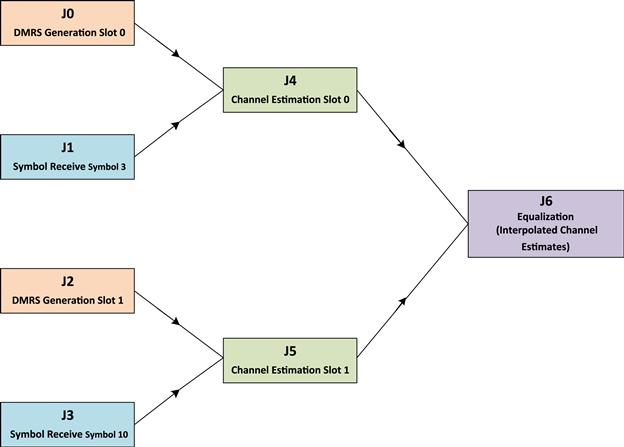
Figure 5: Job dependency matrix.
Using this form of approach the designer can expand the inventory of tasks through adding additional tasks and granularizing existing tasks through a logical division of functionality to provide more alternatives to the Controller for scheduling these tasks separately. For example, the symbol receive functionality can be sub divided into three sub-tasks: Cyclic prefix removal, cyclic shift and FFT. If these additional sub-tasks are also captured in the dependency matrix discussed earlier then the Controller module can schedule them for execution based on their dependency graph and computation requirements. While doing this micro level task break up so that each task can be exercised independently based on the dependency graph, the designer needs to be conscious about performance degradation due to higher fragmentation of tasks. This form of fragmentation can lead to higher inter-core communication as multiple tasks will have to communicate with each other for results and data dependencies. This will also necessitate extensive usage of shared memory in lieu of internal memory. The higher usage of shared memory can lead to higher data latencies as typically the shared memory has higher wait states than the internal memory.
Use Case 4: Static scheduling
The complexity of designing a Controller module that can dynamically schedule various tasks can be very high. The need for an exhaustive and intelligent dynamic scheduling mechanism may not be required when the use case is well defined and bounded. In such a case, a Controller module that is configured statically is a feasible option. This approach lends items itself to simplicity of implementation in Controller logic, as the task partitioning across various cores is estimated statically. This approach also yields to easier debugging against problems as the system behavior is more deterministic. Since the planning for task scheduling is done statically, the system is typically dimensioned for worst case scenario which can, in some cases, lead to non-optimum performance.
The example deliberated in Use Case 3 can be effectively implemented using the static scheduling approach vis-à-vis dynamic scheduling.
In such a case, the Controller module has to be made responsible for initialization of the various system resources and tasks in the processing chain. It also is responsible for maintaining a statically defined table that will identify the different cores on which different tasks will execute. This type of static binding of tasks to the cores imparts a sense of deterministic behavior in the system and simplifies the Controller logic.
In order to effectively schedule various tasks on various cores the Controller software module requires the following three types of information:
1) The inventory of tasks that need to be processed in the system.
2) The order of processing of each task such that for every task there is a list of dependencies. The Controller module should explicitly contain information on these dependencies so that it does not schedule a task unless all its dependencies have been resolved. This can be done through a dependency matrix.
This design mechanism can be illustrated through UL Symbol Processing in Layer 1. Here, the inventory consists of four tasks:
Based on the inventory of the tasks that have been created a sample dependency matrix is shown below.
This matrix shows that tasks J4 can only be executed after completion of task J0 and J1. Similarly, equalization defined as task J6 can only be undertaken after the completion of tasks J4 and J5. This type of dependency information logic should be built into the Controller logic.
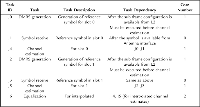
This form of task partitioning shows that at every 1 ms tick from the system, the symbol receive functionality is processed on Core 0 for all the slots. Similarly as soon as the sub frame information is available from the Layer 2, the DMRS generation is enabled on Core 1. Channel estimation is also undertaken on Core 1 and it depends on output result of DMRS generation and symbol receive functionality (Figure 6).
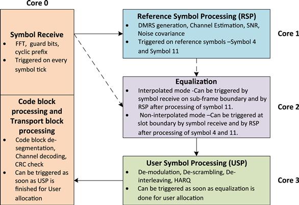
Figure 6: Static scheduling design.
The aforesaid Controller design for supporting static scheduling has tightly coupled the various tasks to a given core. This logic can be extended, to impart a certain decision making capability to Controller. One approach for imparting higher intelligence in the Controller logic is to provide guidelines on binding tasks on a core after taking into consideration a limited set of system parameters. These parameters can be, for example, the number of resource blocks allocated to the user.
Parallelism and pipelining
Multi-core systems naturally lend themselves to the software designer to exploit parallelism in the underlying algorithm. Hence, one of the principal challenges for software designer is to modularize the software into independent and dependent modules that can be executed across the many cores of the system. This also requires identifying the dependency of various tasks on each other. This has been illustrated earlier in this chapter through Use Case 3 and Use Case 4. In these preceding examples we have discussed the task partitioning on various cores of the initial uplink tasks in Layer 1 software.
This section discusses additional techniques to derive parallelism in the Layer 1 processing thereby improving the overall system performance.
Use Case 5: Parallelism in downlink chain
The downlink physical layer data chain lends itself to high parallelism. The software designer can take advantage of this inherent parallelism by choosing architecture specific techniques.Figure 7 provides an example of the various key processing blocks in the downlink processing chain.
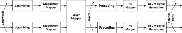
Figure 7: Inherent parallelism in LTE downlink processing chain.
The software designer has three primary methods for choosing task partitioning across cores to leverage higher system performance:
1) Process different code blocks belonging to the same user simultaneously
2) Process the downlink chain for different users independently, but simultaneously
3) After pre-coding, process the Antenna data simultaneously across cores
The software designer, in the downlink can chose to process the different code blocks belonging to the same user simultaneously for the optimum system performance.
When the task partitioning is done across cores as defined in Figure 8, then the parallelism with respect to code block processing is not completely leveraged because even when there is more than one code block the code block processing is done on Core 1, in a sequential manner. This can add latency to the result of the code block processing and this can ultimately lead to a situation where the processing overshoots the 1 ms hard real time window.
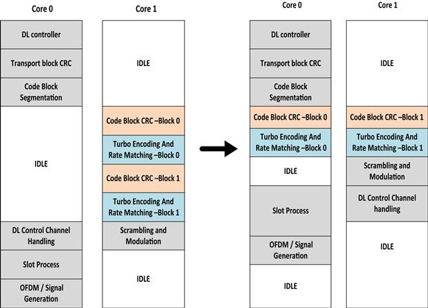
Figure 8: Parallel processing of code blocks to improve core usage and performance.
This scenario can be avoided by ensuring that the code block processing is distributed across both the available cores. The division of code block processing across two cores can be done through different decision making processes. The example illustrated below, in Figure 8, does this such that only the odd number of code block is processed on Core 1. This was experimentally found to create a balanced system as the Core-1 is also used to perform the downlink control channel processing.
Use Case 6: Parallelism in uplink chain
In Use Case 3 and 4 we discussed the first three tasks in uplink processing, namely: Symbol receive, DMRS generation and channel estimation. After this processing the major tasks in the uplink are:
These four tasks are executed sequentially and thus straight forward parallelism is not evident.
Hence, parallelism can be gauged through two different ways:
In order to leverage task parallelism for every independent user, the tasks are distributed such that while all the four tasks are executed sequentially, for each user they are executed on different cores simultaneously. Thus all the four tasks, for every user, are executed on the same core. So if there are four cores available for the uplink processing then the Core-0 is allocated to User-1; Core-1 to User-2; Core-2 to User-3; Core-3 to User-4. Thereafter, the user number wraps around to the core number.
| Core Number | User Number | Tasks on Core |
| 0 | 1 | Equalization → User Symbol Processing → Code block processing → Transport block processing |
| 1 | 2 | Equalization → User Symbol Processing → Code block processing → Transport block processing |
| 2 | 3 | Equalization → User Symbol Processing → Code block processing → Transport block processing |
| 3 | 4 | Equalization → User Symbol Processing → Code block processing → Transport block processing |
| 0 | 5 | Equalization → User Symbol Processing → Code block processing → Transport block processing |
This partitioning scheme is also shown in Figure 9.
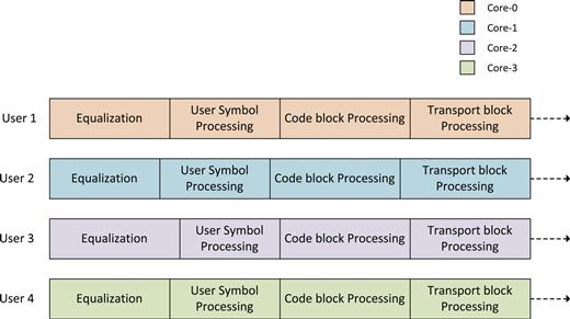
Figure 9: Core distribution based on number of users.
This approach can lead to challenges in deriving an optimum system performance when there is a large variation in resource block allocations to different users. An intelligent scheduling logic can ensure that as soon as processing for one user is completed the Controller logic schedules another user on the idle core.
An alternative mechanism to derive parallelism across users is to assign each of the four tasks to a unique core. Data for all the users that need the task processing have to avail the services of the core on which the task is running.
| Task | Core Number | User Number |
| Equalization | Core 0 | All users |
| User Symbol Processing | Core 1 | All users |
| Code block processing | Core 2 | All users |
| Transport block processing | Core 3 | All users |
The equalization process is assigned to Core-0. After completion of the equalization process for User-1, the equalization for User-2 is computed on Core-0. This process proceeds for every user. The result of equalization process for User-1 is fed to Core-1 where the User Symbol Processing is undertaken. Over a period of time, a pipeline of processing tasks is built across all the four cores such that each core is doing its allocated task for a different user. So at some given instant – Core-0 is doing equalization for User-3; Core-1 is performing User Symbol Processing for User-2 and Core-2 is performing code block processing for User-1 (Figure 10).
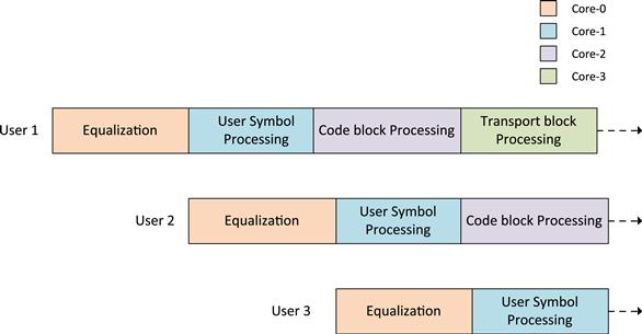
Figure 10: Core distribution based on individual tasks.
This type of task partitioning leads to a very high inter-core communication as all the relevant data for every user has to be made available to the next core which is performing the next task in the processing chain.
The second challenge with such an approach is that the amount of processing per user per task is dependent on key algorithm characteristics such as the number of resource blocks per user that need to be processed. If the number of the resource blocks for the first user is less than the number of resource blocks for the next user then the complexity of every task for the first user will get reduced as there is lesser data to process. This can lead to ‘idle wasted cycles’. For example – if the equalization for the second user takes longer time vis-à-vis the User Symbol Processing for the first user; an idle slot is created on Core-1. This is because while the Core-1 has completed the User Symbol Processing for User-1, it cannot start the User Symbol Processing for User-2 as equalization process for User-2 is still ongoing on Core-0.
Use Case 7: Algorithm parallelism in uplink chain
Use Case 6 has demonstrated mechanisms through which tasks can be distributed across cores leading to an effective utilization of various system resources. This software portioning across cores can be significantly aided by deriving natural points of parallelism in the underlying algorithm.
As started in the example discussed in the Use Case 6; equalization is a computationally intensive task and it can be performed only after the channel estimation is complete.
A simplistic model that exploits first level parallelism is described in Figure 11. This shows that Core-0 is used to perform operations related to symbol receive functionality. Core-1 is used for Reference Symbol Processing based on the symbol information for third and tenth symbol received on Core-0. After the Reference Symbol Processing is complete (which includes channel estimation), equalization task is started on Core-2. The equalization for the current sub frame ‘n’ is triggered after the last symbol (symbol 13) is received in the given sub frame. Figure 11 shows that once the equalization task is started its processing will carry over into the next sub frame ‘n + 1’. The processing required for computing the equalization for 12 symbols received in the sub frame ‘n’ requires an additional time equivalent of 4 symbols. While the design has been able to utilize task parallelism, it has not been able to extract sufficient algorithmic parallelism. Ultimately this will lead to latency in obtaining results for the current sub frame ‘n’. Also, this design approach does not utilize the Core-2 continuously and most of the time the Core-2 is ‘idle’.
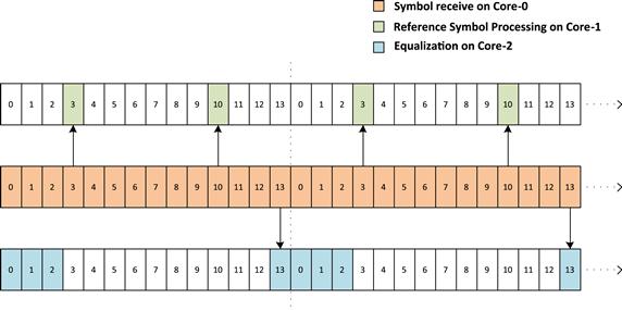
Figure 11: Equalizer design with sub-frame granularity.
The aforesaid design approach can be modified to improve the algorithmic level parallelism. This can be done by ensuring that the granularity of the task processing is changed to symbol level. This means, as shown in Figure 12 that after Reference Symbol Processing is completed for symbol 3 the equalization is started for symbols 0–2. This processing is expected to take time equivalent of 1 symbol, as shown in Figure 12. As soon as all the symbols for slot 0 are received; the equalization is again triggered for symbols 0, 1, 2, 4, 5, and 6. This is found to take time equivalent to 2 symbols.
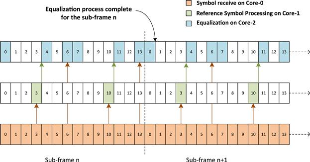
Figure 12: Equalizer design with symbol level granularity.
Similarly for slot 1; the equalization is done after Reference Symbol Processing of Symbol 10 and this takes time equivalent to 1 symbol. After all the symbols related to slot 1 are received, the equalization is again triggered for symbols 7, 8, 9, 11, 12, and 13. This is found to take time equivalent to 2 symbols, as shown in Figure 12.
There are two key advantages of this design. First, the result of equalization for the current sub frame ‘n’ is available in first symbol time of the next sub frame ‘n + 1’. In the previous design, this was 4 symbol time of the next sub frame. Second, the Core-2 is more evenly loaded and hence better utilized.
The key challenge that still remain is that the equalization results for the current sub frame ‘n’ are only available in the next sub frame ‘n + 1’. Hence this approach still adds to the overall system latency.
The aforesaid design approach can be further modified to ensure that the equalization result for the current sub frame ‘n’ does not get computed into the next sub frame ‘n + 1’. This type of implementation requires a deeper deliberation on the equalization process.
Equalization (![]() ) using Interference Rejection Combining (IRC), includes an estimate of the transmitted symbols in the frequency domain according to the following equation
) using Interference Rejection Combining (IRC), includes an estimate of the transmitted symbols in the frequency domain according to the following equation
![]()
In this equation the key input parameter are the Number of Receiver antennae (NRxAnt) and the Number of Transmitter antennae (NTxAnt). Based on the received data the following additional information is derived:
| Equation Variable | Value Represented | Value derived from |
| H | Channel estimates | Matrix of NRxAnt rows and NTxAnt columns |
| r | Received symbols | Matrix of NTxAnt rows and NRxAnt columns |
| Pn | Noise covariance matrix | Matrix of NRxAnt rows and NTxAnt columns |
| Cx | Covariance matrix of transmitted signal | Matrix of NTxAnt rows and NRxAnt columns |
The aforesaid equation can be represented as
![]()
In this equation,
![]()
The most important property of the matrix ‘A’ is that it is dependent only on Reference Symbol Processing (i.e. channel estimates, transmit covariance and noise covariance). As there is only 1 reference symbol per slot, the matrix ‘A’ will remain same for a complete slot when non-interpolated channel estimates are used. As a result, the matrix ‘A’ can be computed immediately after the processing of reference symbol as shown in Figure 13.
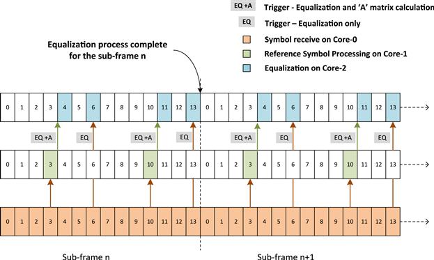
Figure 13: Equalizer design with division of algorithmic computation into several tasks.
In this example, immediately after the symbol 3 is received, the matrix ‘A’ is computed on Core-2. Along with this the equalization results are also computed for the symbol 0, 1, 2 on the Core-2.
Now, as soon as Core-0 receives Symbol 6 the equalization is triggered on Core-2 for symbol 5, 6, 7. This uses the matrix ‘A’ calculated earlier. In this manner, the equalization for the last three data symbols is made even more simple without involving the re-calculation of matrix ‘A’ and hence, the overall system latency is improved by ensuring that the equalization processing results are available in the same slot of the current sub frame.
Use Case 8: Sub-frame pipelining in uplink processing
One of the key challenges in uplink processing is that the processing of the complete sub frame ‘n’ is dependent on receiving all the symbols of that sub frame. As discussed in the examples illustrated in Use Case 7, it is possible through efficient design techniques to ensure that for the current sub frame ‘n’ the symbol receive, Reference Symbol Processing and equalization of data symbols can be completed in the same sub frame ‘n’. However, it is not feasible to complete the entire uplink chain processing in the current sub frame boundary. User Symbol Processing, code block processing and transport block processing are invariably carried over to the next sub frame.
Figure 14 shows that the code block processing is performed on the Core-3. For the current sub frame ‘n’, the code block processing completes toward slot 1 of the sub frame ‘n + 1’. This creates a natural latency of one sub frame which is unavoidable, as explained earlier. Overall, this approach demonstrates an extremely parallelized approach where two levels of parallelism have been exploited. At the first level the parallelism is attained by partitioning various uplink tasks across different cores. At the second level, this task partitioning is enhanced to also take into account algorithmic parallelization.
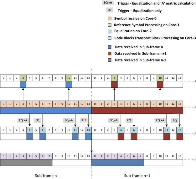
Figure 14: Parallel pipeline of tasks between sub frames.
Load balancing
One of the key goals for an efficient software design on a multi-core architecture is an ability to create a system that is fully load balanced. A load balanced system ensures that all the cores are effectively used and the number of idle cycles is reduced to the minimum possible, for a finite number of use case scenarios. Indirectly, a fully load balanced system also ensures that the software designers have been able to exploit the process parallelism and data parallelism adequately.
The discussion in Use Case 3 and Use case 4 had introduced the concept of a Controller module that manages the scheduling of tasks across the system. The Controller module can itself be working on one core which is used as a master core to control the various tasks in the system.
This can be effectively done through a creation of the dependency matrix. This dependency matrix should contain an exhaustive list of all tasks that need to be performed along with information on the dependency of each task toward others tasks in the processing chain. The Controller logic can then ensure that unless all the dependencies of a task are executed, the task is not scheduled for execution. This form of basic intelligence in the Controller logic avoids idle core cycles by not scheduling tasks that are not ready for execution.
In order to assist in additional load balancing, the Controller can be imparted with higher intelligence by ensuring that the Controller is also aware of the amount of processing required for a particular task and the amount of processing cycles available across various cores. This form of information to the Controller ensures that the Controller is able to bind the tasks to the most appropriate core, based on the number of processing cycles available on that core.
The overall functionality of scheduler with load balancing can be summarized in Figure 15.
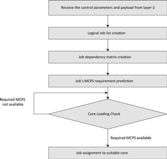
Figure 15: Load balancing scheduler.
Hardware accelerators
Philosophy behind hardware acceleration in DSP systems
Advanced multi-core SoC are increasingly assisted by complex hardware accelerators to perform computationally complex activities. As a result, the overall system performance becomes dependent on partitioning of tasks across cores and an efficient usage of the hardware accelerator capability.
The hardware accelerators lend themselves to multiple advantages related to speed of software implementation and significant reduction in testing costs as the functionality is abstracted in hardware; offloading critical tasks from core to dedicated hardware which helps in making the system performance more deterministic and lower power consumption as the accelerators work at a lower clock frequency.
Hardware acceleration in baseband (LTE eNodeB) infrastructure
This section illustrates through a series of examples, usage of the hardware accelerator for Layer 1 processing. For the purpose of this discussion the hardware accelerator described in the examples is an advanced co-processor called Multi-Accelerator Platform Engine for Baseband (MAPLE-B). MAPLE-B is available on Freescale’s MSC8156 Multi-core processor. It consists of a programmable controller called Programmable-System-Interface (PSIF), a DMA and four processing elements:
• CRCPE (CRC Processing Element)
• TVPE (Turbo/Viterbi Processing-Element)
These processing elements (PEs) can be used in interrupt based or polling based modes. The MAPLE-B model avoids repetitive setup overhead on the various processing elements by allowing a single job preparation and trigger mechanism.
The Layer 1 software can leverage the MAPLE-B capabilities from the user space through a set of well defined APIs for different functionalities.
Use Case 9: Hardware–software partitioning for downlink shared channel processing
Figure 16, shows the complete downlink chain processing for an LTE Layer 1 implementation. In a pure per se multi-core architecture the implementation of the entire chain is required in software. However by using the hardware accelerators, such as MAPLE-B in case of MSC8156 multi-core, various computationally intensive blocks have been offloaded to the hardware accelerator.

Figure 16: LTE eNodeB shared data downlink processing chain.
The hatched blocks in Figure 16, depict the various functionalities that are mapped either fully or partially on to the hardware accelerators. These include:
1) The transport-block (TB) CRC computation is mapped on the CRCPE of MAPLE-B hardware accelerator.
2) The code-block (CB) CRC computation is also mapped on the CRCPE of MAPLE-B hardware accelerator.
3) At the time of generating the OFDM symbol the FFT operation is mapped to FFTPE of MAPLE-B hardware accelerator. Along with performing FFT, the FFTPE hardware accelerator is also used to insert the guard sub-carriers.
Use Case 10: Hardware–software partitioning for uplink shared channel processing
Figure 17, shows the complete uplink chain processing for an LTE Layer 1 implementation.
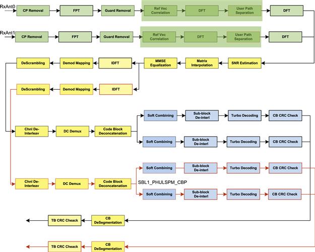
Figure 17: LTE eNodeB shared data uplink processing chain.
The hatched blocks in Figure 17, depict the various functionalities that are mapped either fully or partially on to the hardware accelerators. Hardware co-processor plays an important role in uplink processing in managing the high computation requirements for processing the reception of symbols and subsequent tasks for hundreds of active LTE users. The MAPLE-B accelerator is hence leveraged for the following tasks:
1) After the OFDMA symbols are received – the Cyclic Prefix (CP) removal, FFT computation and guard removal is performed in the FFTPE
2) The time-domain channel estimation uses DFTPE for the IDFT and DFT operations
3) The IDFT functionality required to retrieve the modulated symbols from equalized user data is performed using the DFTPE
4) Viterbi decoding and Turbo decoding are computed using TVPE. TVPE internally uses CRCPE for Code Block CRC check
Use Case 12: Pipelining and parallelism in uplink shared channel processing
Figure 18, demonstrates potential pipelining and parallelism in a system design involving multiple core and MAPLE-B hardware co-processor for LTE Layer 1 uplink shared processing. As explained earlier in the section, the MAPLE-B co-processor supports DFT/IDFT and Turbo decoding processing engines. They can run independently and simultaneously.
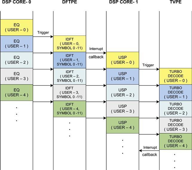
Figure 18: Parallelism between processing in HW and SW.
As shown in Figure 18, the IDFT operation is being executed on MAPLE-B in parallel to the Equalization operation being executed on core. After IDFT, the User Signal Processing (De-modulation mapping, De-scrambling, De-interleaving, De-multiplexing and code block de-concatenation) on core is run in parallel to Turbo decoding operation on MAPLE-B hardware co-processor. The above design clearly boosts the overall throughput performance by reducing the uplink execution latency.
Case Study Part 2: Wireless Baseband Software on Multi-core – Layer 2
Akshitij Malik, Umang Garg
Introduction
New generations of wireless protocols such as LTE lend themselves to the advantages of high throughput and improved spectrum utilization, resulting in improved user experience and improved Return on Investment (RoI) for service providers. These advanced protocols demand higher processing capabilities from the underlying processor architecture. The increased processing requirements can be efficiently managed through a new generation of multi-core architectures such as Freescale’s P4080 System-On-Chip (SOC).
The adoption of advanced multi-core embedded platforms has also increased the traditional software development challenges to include emerging challenges such as: ability to use the multi-core devices effectively, adopting evolving tools, flexible software partitioning, deriving sequentially higher performance, and achieving an ever increasing software quality requirement. The ability to effectively enable the same software load on multi-core devices with different numbers of processing cores and with minimal changes to the software is another evolving challenge.
This discussion illustrates through a real life, wireless protocol software lifecycle, the art & science of navigating these challenges effectively.
Process and quality
Guiding principles
Software development on multi-core platforms is an evolving paradigm. The foremost step towards a dependable software development on multi-core devices is the need for a Quality driven methodology to ensure that the challenges introduced by evolving technology leaps do not overwhelm the software development cycle and degrade the customer experience. The need for higher quality is greater than ever before.
The 5 key Quality principles that can assist in ensuring a successful development cycle are:
Agile development practices
For a process purist, the science of Agile development methodology is a well documented subject. For a team focused on delivering complex software on complex hardware within a definite business critical timeline, Agile practices are a means to maximize productivity, enhance delivery effectiveness, and create a positive ROI. Agile development practices are well suited to evolving multi-core platforms where teams are challenged to satisfy customer needs for delivering complex software on the new devices while they are still learning about the intricacies of the new generation of silicon platforms. A key qualitative requirement for the methodology to succeed is a close, intra-team collaboration while a key quantitative requirement is the adoption of project discipline through metrics such as: Phase Containment Effectiveness, Root Cause Analysis, Monthly Defect Reports, Cyclomatic Complexity, and Test Coverage Data.
Modular software design
As this text shows later, when the software quality practices enforce a requirement for modular software design with well defined interfaces, clear tabulation of memory requirements and test modularity and then adapting the same software to different software portioning requirements becomes feasible with significantly lower overhead. Moreover, isolation and simplification of the application into small, simple modules automatically allows for integration of Agile methodologies in the development of such software.
Refactoring
The quality practices should enable the process of continuous design and code refactoring to support an ever increasing understanding of the platform architecture. When the code is continually re-factored, the process is bound to introduce new defects and thereby reduce the software quality. A modular software design which can be tested modularly reduces this risk by ensuring that all interfaces for various defined use cases and configuration parameters are tested. Tests which validate the application at individual module-levels also help isolate the problem areas. Ultimately, the advantage accrued from refactoring has been found to improve system performance and advanced functionality exploitation. The advantages outweigh the short term challenges.
Reuse
The intensity of product development is invariably determined by the ‘time to market’ requirements. More often than not, a product development has to fit the time to market deadline, rather than the other way around. A deliberate choice is recommended when considering reuse of the software or parts of it. This decision making process is crucial when the software may not have been originally designed for the multi-core architectures and architectures which may contain ‘many core and associated accelerators.’ This study builds on examples where certain parts of the software were re-written completely and many parts were reused with minor modifications. An appropriate balance is necessary. The choice can be determined based on the nature of the changes required to migrate to a multi-core platform, the number of changes, and the impact of the changes on the existing collateral such as test cases and documentation. As a general guideline and as a heuristic exercise – if the number of changes is more than 50% lines of code and more than 50% lines in the associated collateral then a software designed from scratch is a better alternative to creating a maze of fixes on a legacy working software. If the number of changes is less than 20% of code and collateral then, it is advisable to reuse the existing software. If the number of changes is between 20% and 50% then it is better to identify sub-modules that can be reused with some patchwork and sub-modules that need to be rewritten.
Product quality software requires sustained focus on easy to use and up-to-date documentation on requirements, design, and test. Additionally, product quality software is an outcome of non trivial test focus that seeks to ensure that the software does what it is supposed to do.
In fact, more than 50% of the engineering time is found to be spent on activities related to development of test cases and documentation efforts related to requirements, design, and test. It is hence essential that while code refactoring and software reuse is practiced diligently, there is an effort to ensure that the documentation and test collaterals are generated in a way that their upkeep is made simpler. Tools such as Doxygen (refer to [1]) can be leveraged to generate accurate and relevant detailed design information. This can allow the design documents to be at a higher level of detail while low level details are documented through informative comments in the code which are captured through Doxygen. This allows the low level documentation to be dynamically updated as the code changes through refactoring.
Tools
Mature software tools for development are an essential part of the development process for high quality, complex software. When the development platforms are new and evolving, the software tools are also found to be in an evolutionary lifecycle of their own. This imparts an additional level of complexity to the software development cycle as a single tool suite cannot be adopted to enhance the development process. The development process has to hence enlist the support of multiple tools. Some of these tools may be open source and others maybe proprietary and hence essentially bundled with the SoC’s enablement software. While all tools are important, for the purpose of this discussion we have put the tools in 5 broad categories:
• Category 1 tools essentially enable software compilation, assembling, and execution of the target platform. They must hence provide the aforesaid capabilities in a dependable way.
• Category 2 tools enable debugging and profiling. Most often the maturity cycle of these tools lag the category 1 tools. At the very least, these tools must provide minimal command capabilities for debugging, such as setting breakpoint, step wise execution, etc. More mature debugging tool set provide higher visualization, trace information, etc. The support for code profiling is essential to measure and understand the performance impact of the software functionality under various use case scenarios. The most essential profiling support is the ability to measure CPU core cycles, cache hits, cache misses. Profiling tools with higher maturity confer the ability to analyze a large number of registers available within the SoC. These registers/counters can enable improved software development through knowledge of hierarchical cache behavior, function wise profiling capability, etc.
• Category 3 tools enable development process through Simulation software. The simulation environment is typically a functionally accurate representation of the silicon environment and can hence enable pre-silicon development thereby supplementing the ‘time to market’ requirement. A more evolved simulation platform also provides a ‘cycle accurate’ environment.
• Category 4 tools are typically the general purpose software tools. These include static analysis tools that enable the development team to browse the code, gather statistics such as line count, and measure Cyclomatic Complexity etc. This category also includes tools such as bug management tools, static defect analysis tools, configuration management tools.
• Category 5 tools are the differentiator tools that can enable the development teams to evaluate the impact of their development platform on the software being development. These tools provide ability to analyze software partitioning choices, isolate concurrency issues, etc.
Software blocks and modules
The enhanced Node B (eNB) is a key network element in the LTE network (refer to [3]). The eNB functionalities include both Control Plane and Data Plane Processing. The data path of eNB has 2 primary interfaces to the rest of the LTE network:
• S1-U Interface. The S1 interface is an IP based interface and it is used to exchange data packets towards the rest of the LTE network using IP-based protocols.
• LTE-Uu air-interface. The LTE-Uu interface is used to exchange data with the actual Mobile Stations (UE) over the wireless medium. The LTE-Uu consists of specific protocols that are meant to handle the LTE’s wireless transmission technology.
The S1 and LTE-Uu interfaces consist of multiple protocol sub-layers which form the protocol stack of the eNB. Each of these protocol sub-layers has its own independent functionality and thus is treated as a separate module/sub-modules.
Figure 19 gives a diagrammatic representation of the eNB data-path.
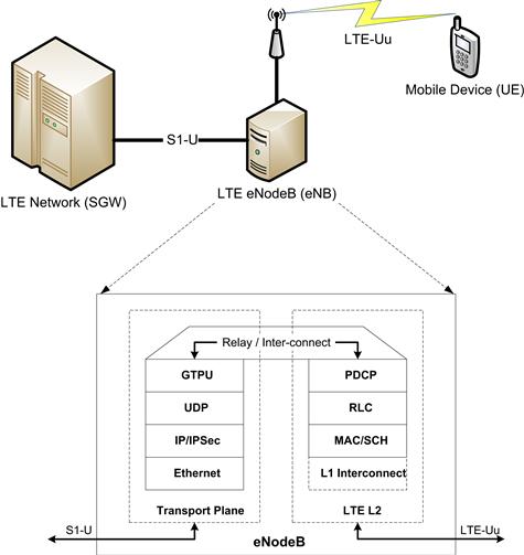
Figure 19: LTE eNodeB protocol stack.
The challenges experienced in the migration of single-core software to multi-core and their resolutions can be explained through the example of eNB software. The eNB software is collectively termed eNB_App.
As part of the modularization exercise, the eNB_App has been logically separated into two software blocks: the Transport block and the Layer 2 block.
The Transport block has further been modularized on the basis of the protocol sub-layers that are implemented within it. It consists of two modules:
Similarly, the Layer 2 software block has been split into three modules:
In addition to the protocol sub-layers of the Layer 2 software block, a simple Scheduler (SCH) sub-module has also been developed to carry out the scheduling of packets that are to be transmitted over the LTE-Uu interface. The SCH sub-module is a simple FCFS type of scheduler which has been integrated with the MAC sub-module.
The Transport software block along with the PDCP module is responsible for processing the packets received asynchronously at the S1 interface. The LTE-Uu interface requires frames to be exchanged between the eNB and the UEs at an accurate 1 ms timing. The synchronous processing of the LTE-Uu data takes place within the RLC and MAC software modules. The RLC and MAC modules, owing to their synchronous nature, have hard real time constraints and are required to perform processing within 1 ms.
Figure 20 gives a high-level representation of the arrangement of sub-modules within the eNB_App.
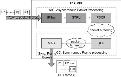
Figure 20: eNB_App sub-modules.
The IPSEC module is responsible for implementing the IPSec related functionality of the eNB. It processes the encrypted packets on ingress and applies the required decryption algorithms to extract and verify the payload. On the egress side, it identifies the security association of the outgoing packet and using that, it generates the encrypted IPSec packet that can subsequently be securely sent towards the destination.
The GTPU module receives the GTPU packets that were tunneled in the payload of the IPSec packets and identifies the data-transmission context towards the LTE L2 stack. It makes use of the addressing information along with the GTP Tunnel identifiers for this purpose. Similarly, during egress, the GTPU module receives the packets delivered by PDCP and identifies the outgoing GTPU context by building the GTPU headers containing the GTPU Tunnel identifiers, etc.
The PDCP module, along with the GTPU modules, acts as a relay between the Transport Stack and the LTE L2 Stack. The PDCP module receives the data of individual user-streams and (if configured) it applies the header compression algorithms to reduce the packet size which reduces the number of bits that need to be transferred on air. In addition, during handover the PDCP module forwards the buffered packets that have not yet been delivered to the UE towards the Target eNB. In the uplink (egress) direction, the PDCP module receives the data delivered by RLC and (if configured) it applies the header decompression algorithms to recover the header information that is relevant for the data-stream. The PDCP will then forward the packet with the uncompressed headers towards the GTPU along with the appropriate context identifier that would help GTPU identify the tunnel on which the packet must be sent out.
The RLC module is primarily responsible for carrying out link-level handling of UE data. In the case where the RLC is configured to operate in the Acknowledged Mode (AM Mode), it also performs ARQ functionality to ensure reliable delivery of the UE’s data. The RLC module is also responsible for buffering data as it is scheduled for transmission and also when it is being re-constructed from multiple RLC PDUs during reception.
The MAC module (along with Scheduler functionality) is responsible for interfacing with the L1 layer of the eNB to send or receive UE’s data over the air. The MAC module is responsible for selecting the UEs and their Logical Channel that transmit or receive data in each 1 ms frame. In addition, it is responsible for multiplexing data from multiple UEs (and their multiple logical channels) into a single frame for transmission and similarly, extraction of data from each of the UEs in the received frame. It also performs the task of HARQ processing to ensure efficient and reliable exchange of data between the eNB and the UE.
Single core application
SoC with high performance single cores have been the bedrock of embedded software development for a generation of engineers. These environments, through the natural evolution of their maturity, are accompanied by stable development tool chain, simplicity of programming choices, and early cycle tradeoffs on software capability (which itself is closely tied to use case requirement as well as the hardware capability).
Applications developed for single core platforms require minimal design choices on SW partitioning across cores. Depending on the expected number of core cycles and memory requirements for processing, the SW partitioning challenge is often resolved through usage of multiple SoC. This approach limits the flexibility for changing the software partitioning as it impacts software running on multiple SoC and the overall system architecture. Any changes to the SW partitioning also lead to an addition in the cost of SW Testing and changes to the associated collateral. Such solutions also face a limitation imposed by the data-transfer mechanisms that may be employed to exchange data across the SoC devices.
For the identified software blocks and modules in Software Blocks and Modules, when single core SoCs are available, the two plausible partitioning approaches may be:
This approach simplifies the design and partitioning choices by executing the complete stack on one single core SoC (Figure 21).
Figure 21: eNB_App – single-SoC design.
Following such an approach, all the blocks of the eNB_App execute on a single single-core SoC. While such an approach appears to be the simplest, however, the designer needs to be careful that the hard real-time requirements of the 1 ms frame processing are met under all circumstances. This adds the burden of dimensioning each of the modules such that each module completes its processing well within a fraction of the 1 ms frame tick. Additionally, since the system dimensioning has to be done considering the worst-case processing times of each of the modules, it may not be possible to maximize the system utilization (since sufficient headroom must be maintained).
This approach also reduces the capability of the software to impart scalability for (future) use case requirements due to a finite processing capability:
b) Figure 22 shows transport software running on one SoC and the L2 software running on a second SoC
Figure 22: eNB_App – multi-SoC design.
This approach allows the developers to implement the application more flexibly than with the Single-SoC approach.
The asynchronous, packet-triggered network processing modules (NIC) can be run on one thread associated with the first single core SoC, while the synchronous, timing sensitive part (CC) can run as an independent thread on a different single core SoC.
Compared to the previous approach in Transport and L2 software running on the same SoC, this design allows each set of sub-modules within the NIC and CC to maximize their respective performance. It may be possible to even use different SoCs for the NIC and CC – each having their specialized accelerators to further enhance performance.
However, this form of multiple SoC architecture leads to a higher bill of material cost, increased power consumption due to multiple SoC, and increased complexity of overall architecture. Additionally, the performance gained due to the reasons mentioned above may get offset by the latencies introduced due to limitations in the data transfer mechanism between the two SoCs. Finally, as this is a specific fixed arrangement of the SoCs, the scalability of the overall solution is limited.
An example of a multi-core SoC: P4080
The P4080 (shown in Figure 23) SoC is a high performance multi-core device. It consists of eight e500mc cores and multiple hardware accelerators that are designed to simplify the development of networking applications and yield high performance. The P4080 core usage is flexible and allows the eight cores to be combined as a fully-symmetric, multi-processing SoC, or they can be operated with varying degrees of independence to perform asymmetric multi-processing. Each of the cores may be used to execute independent systems. This allows the P4080 to be used with significant flexibility in partitioning between control, data-path, and applications processing. Additionally, the quantum of processing capability provided by the cores and the associated hardware accelerators allows consolidation of functions previously spread across multiple discrete processors onto a single device.
Figure 23: P4080 High-level block diagram
Figure 24 shows a high level block diagram of the P4080 multi-core SoC. Hierarchical cache architecture and numerous accelerators on the device are a key differentiating factor resulting in improved software solution performance. The primary accelerators include:
• Security Engine (SEC), which can be leveraged for encryption and decryption
• Buffer Manager (BMAN) for memory allocation and management
• Queue Manager (QMAN) for intra system communication
• Frame Manager (FMAN) for high speed exchange using the Ethernet interface
For most end-users, it is not practical to write software to directly interface with the SoC hardware. Typically, a hardware abstraction layer is used which allows the higher layer applications to interpret the hardware using more generic APIs. For the P4080, the Light-Weight Executive (LWE) is one of the hardware abstraction layers. The LWE consists of software APIs which allow configuration of the hardware such as the DPAA modules – allowing the Data-path (DP) functionality to exercise the DPAA modules that support the DP functions.
Figure 24: Enablement software on P4080 - LWE.
Migrating to multi-core
Advantage
For the same deployment scenario and as compared to a mish mash of single core SoC, multi-core embedded architectures are a natural choice due to their inherent advantages such as lower bill of materials cost as well overall cost of ownership, lower power consumption, higher (future) scalability, and higher performance. Multi-core embedded SoCs are relatively new phenomena and hence committed engineering effort is required to realize the various advantages offered by the platform.
In the following sections, using the eNB_App as an example, we shall highlight the steps that may be followed to adapt current software applications from the single-core to the multi-core environment.
In order to directly develop applications for the multi-core environment, a similar series of steps may be followed.
Multi-core considerations
In addition to the standard design issues of single-core applications, the following issues have to be considered when designing applications for multi-core environment:
The issues experienced in developing software for multi-core platforms can be addressed through a series of four steps:
As a part of the Atomization step, the software designers need to identify various independent operations that can be performed on the received data. These operations can then be placed into separate modules or sub modules. These sub modules should have well defined interfaces for data exchange with other sub modules so that each sub module can work independently.
Advanced multi-core devices such as P4080 provide easy to use mechanisms for the (implicit) distribution of sub-modules across the cores. These mechanisms along with relevant examples have been explained in detail in Advanced Accelerator Usage on P4080: Practical Examples.
The next step is Serialization. As a part of the Serialization process, the software designer should identify the sequence in which the various modules and sub modules are required to execute. As a part of the serialization the designers need to take into account the method for sharing the packet context across various sub modules in an optimized manner for improved system performance. While sharing the packet context it is also essential to ensure that the concurrency issues are taken into account during the redesign phase.
In architectures such as P4080, the concurrency challenges associated with sharing the packet context can be simplified due to the underlying nature of the platform. As one possible approach, this can be undertaken by associating each context with a different Frame Queue. In situations where two or more modules executing on independent cores may access the same resource, then these resources must be protected using suitable mechanisms such as spin-locks, mutexes, etc.
The next step is the Distribution of the atomized and serialized modules on the available cores. This distribution is a function of the use-case required to be addressed, the estimated performance requirements of the modules/sub-modules, and any legacy design preferences.
Finally, the complete software requires Balancing for optimum system performance and for ensuring future scalability. This step may require modification of the distribution scheme undertaken in the previous step. It is recommended that for purpose of future scalability, none of the cores should be loaded more than 70% under maximum load conditions as defined by the given use case.
The procedure explained above was used to migrate a Single-Core eNB_App to a Multi-Core solution using the P4080 platform as the basis. Figure 25 highlights the work-flow as the eNB_App was re-factored using the steps – atomize, serialize, distribute, and balance. The detailed procedure that was followed in the migration is explained in the following sections.
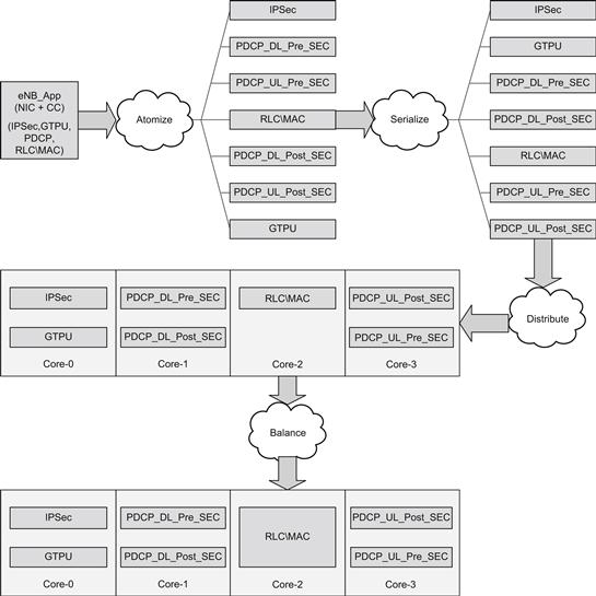
Figure 25: Refactoring the eNB_App for Multi-Core P4080.
Single Core to Multi-core
As discussed earlier, multi-core SoCs can be treated as a multi-threaded environment. So migrating from single-core to multi-core SoCs may be treated as an exercise of parallelizing a single-threaded application. The point of consideration is that there may be restrictions on the number of “threads” that can be spawned in the multi-core SoC environment. Additionally, since multi-core SoCs often also come with a rich set of accelerators, additional effort is needed to incorporate the use of the available accelerators within the application.
The migration of existing software from a single-core SoC to a multi-core SoC can be accomplished through the sequence of steps identified in Figure 26 below:
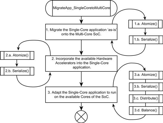
Figure 26: Steps to migrate to Multi-Core application.
Step 1: Transplanting the single-core application to the multi-core SoC
The first step towards adopting a multi-core SoC is migrating (existing) single-core SoC application software to a single core of the multi-core architecture. This method allows early adoption of the new platform and is typically expected to lead to minimal software changes.
In the case of the eNB_App, this implies that we directly just port the Single SoC application to execute on a single core of the P4080. The execution loop of the eNB_App is run on any one core of the P4080 while the remaining cores are idle (Figure 27).
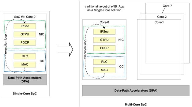
Figure 27: Transition for single-core SoC to multi-core SoC.
As can be seen in Figure 28, when adapting an existing single-core application to run on a multi-core SoC, the focus is on keeping the transition simple and minimalistic. In the code above, the only changes made to the existing application are to ensure that it executes only on one (CORE_0) of the available cores of the multi-core SoC.
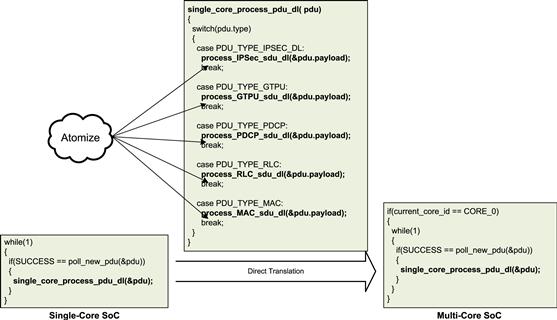
Figure 28: Direct translation of single-core code to multi-core.
In addition, it is useful to atomize and serialize (Steps 1.a. and 1.b. in Figure 26) the existing modules of the application as part of enhancing the adaptability of the software on the new platform. At this stage, only a bare minimum effort should be spent on atomization and serialization.
Step 2: Leveraging the hardware accelerators on the multi-core SoC
The second step towards adopting a multi-core architecture is to leverage the hardware accelerators supported on the hardware platform. This step will require changes to the software for leveraging the hardware accelerators. Hence, an initial understanding on the capability of the hardware and its usage is essential.
This is an appropriate stage to atomize and serialize the sub-modules of the application (Steps ‘2.a.’ and ‘2.b.’ in Figure 26) with the aim of maximizing the utilization of the available hardware accelerators.
The eNB_App first leveraged the Buffer Manager (BMAN) capabilities available on the P4080. A robust Buffer Management is a key functionality in any embedded software. By offloading the buffer management responsibilities such as allocation, de-allocation and memory management to the BMAN it is possible to reduce the software logic that would otherwise be required for a complex software buffer management sub-module.
The BMAN allows data to be available to the various cores of the SOC and its various accelerators, with minimal data movement (and copy) and without the need for translation.
The eNB_App then leverages the capabilities of the Security Engine (SEC) available on P4080, as shown in Figure 23. The SEC supports multiple encryption and decryption algorithms which are required by modules such as PDCP and IPSec. The IPSec module uses algorithms such as the DES/TDES to encrypt & decrypt packets exchanged with other nodes in the LTE network. The PDCP module uses the SNOW-3G F8-F9 algorithms to cipher and decipher data exchanged with the UEs.
As a part of the second step both these modules were adapted to interface with the SEC block to offload the computationally expensive encryption and decryption and cipher and deciphering of the user data. This involved re-writing of a sub-module in the PDCP that was responsible for interfacing with the encryption and decryption algorithms. Significant processing load of the ‘cores’ that were used in performing the encryption and decryption of user-data was hence reduced by offloading these tasks to the SEC block.
The next IP that was used was the Frame Manager (FMAN) on P4080, as shown in Figure 23. FMAN provides capabilities to parse the protocol header of the received packets and subsequently using the user configured policy rules, it can distribute these packets. As a result, the software sub-module that was responsible for the identification of the incoming IPSec packets and their Security Association (SA) to FMAN was deprecated and the work was offloaded to the FMAN. This step required minor changes in the implementation of the IPSEC module.
Subsequently, the FMAN block was used to perform checksum calculation and validation which led to further saving in the core cycles.
Finally, the Queue Manager (QMAN) provides a message-queue kind of IPC mechanism along with advanced capabilities such as prioritization of messages and message order guarantee, etc. The QMAN was thus used to uniformly replace the IPC used across all the modules and sub-modules of the eNB_App. Since the QMAN is ‘aware’ of the multi-core environment of the P4080, it contains support to handle concurrency related issues. This important capability provided by the QMAN has been heavily used in the next phase.
As a result of following Steps 2.a. and 2.b. in Figure 26, the PDCP module was further atomized into 2 sub-modules – pre-SEC and post-SEC. As part of the serialization, the arrangement of modules should be such that PDCP pre-SEC execute occurs first, followed by delivery of the cleartext data to the SEC block for ciphering. The ciphered payload is received back by the PDCP post-SEC sub-module to complete the PDCP to SEC offload. A similar approach was followed for the IPSec module.
As can be seen in Figure 29, in the downlink (DL) direction, the PDCP performs five primary tasks – Buffering of the received SDUs, Compression of network headers within the SDU, and ciphering of the PDCP PDU payload before its header is created and a PDU is formed and sent towards the RLC. To offload the task of ciphering to the SEC block, the process_PDCP_sdu_dl function that processed the PDCP SDUs in the DL direction was atomized into two atomic functions – process_PDCP_sdu_dl_preSEC and process_PDCP_sdu_dl_postSEC. Serialization of the operations across the two atomized functions was ensured since these are connected to the SEC block using QMAN which guarantees in-sequence delivery of queued data.
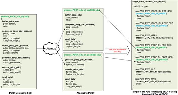
Figure 29: Adapting the single-core app to leverage SEC4.0.
Figure 30 shows the eNB_App using the SEC block for encryption and decryption while the FMAN block is being used to offload the IP Header pre-processing and routing of incoming IPSec packets.
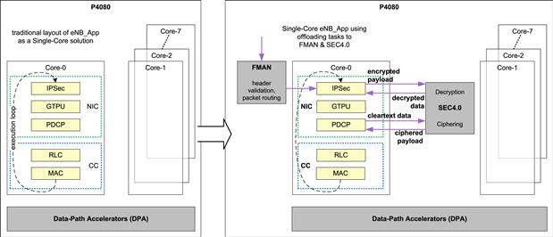
Figure 30: Offloading processing to DPA on multi-core.
The indirect effect of using the hardware accelerators was the improvement of the overall quality of the system. This was accomplished as result of:
• Higher degree of ‘reuse’ since the hardware accelerators are commonly used across various modules
• Reduced code size which results in greater focus on the task at hand
• Less software code statistically implies fewer defects
• Less software code can be reviewed, tested, and covered even more thoroughly
Step 3: Distributing the application on the multi-core SoC
The third step for effectively leveraging the multi-core architecture is using the multiple cores along with the hardware accelerators, thereby realizing the complete potential of the architecture. This requires the software designers to analyze and determine the most appropriate software partitioning approach that satisfies the use case and also facilitates a method for future scalability.
This phase of application refactoring primarily involves distribution of the modules and sub-modules across the available cores as well as balancing the load generated on each core so as to maximize the overall performance of the system. Steps 3.c. and 3.d. in Figure 26 target these tasks. In addition, as a result of distributing the sub-modules across multiple cores, or as a result of the need to balance the system, some further atomization and serialization of some sub-modules may be needed.
After following Steps 3.c. and 3.d. in Figure 26, in the first iteration we can distribute the NIC and CC functionality across two of the cores of the P4080. As a result, Core-0 of the P4080 is used for processing the modules associated with the transport stack and Core-1 is chosen for processing the sub-modules associated with the LTE L2 stack. However, since the timing requirement of the PDCP sub-module is different from the RLC and MAC sub-modules, as part of the balancing of the system, the PDCP module is also executed on Core-0.
To move to the two-core solution proposed above, the DL SDU processing function for the single-core solution – single_core_process_sdu_dl, was first atomized into two logically independent functions – process_sdu_NIC and process_sdu_CC. These functions could then easily be distributed across the two cores of the P4080 by adapting the main processing loop to use only the specific SDU processing functions on each of the cores (Figures 31 and 32).

Figure 31: Two-core distribution of eNB_App.
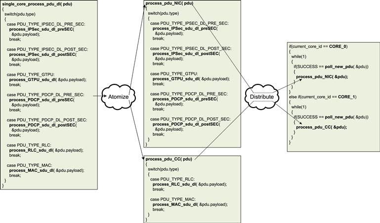
Figure 32: Distributing the NIC and CC across two cores.
A performance analysis of each of the sub-modules was done to assess their CPU Core-Cycle requirements. Figure 33 depicts an approximate distribution of the Core-Cycles that were consumed by each of the modules when running on a single Core. By offloading the encryption/decryption functionality to SEC, the processing requirements of the IPSEC module reduced significantly. The RLC and MAC modules consumed the highest proportion of Core-Cycles. In case of the PDCP module, it was found that the additional processing required by RoHC created a system imbalance and reduced the system throughput. As a result the eNB_App was re-factored and PDCP module was further atomized into Uplink (UL) and Downlink (DL) execution legs. These execution legs were then distributed to independent cores.
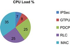
Figure 33: Load distribution for 1-sector on single-core application.
Using the information on the Load Distribution analysis along with the logical function that each sub-module performed, the sub-modules were distributed in the following manner:
Core-0: Transport functionality – IPSec + GTPU modules
Core-1: PDCP-DL functionality – PDCP_DL_Pre_SEC + PDCP_DL_Post_SEC sub-modules
Core-2: Frame-driven Sector functionality – RLC/MAC + PHY Sim sub-modules
Core-3: PDCP-UL functionality – PDCP_UL_Pre_SEC + PDCP_UL_Post_SEC sub-modules
Scalability of the eNB_App to a 3-Sector solution was also kept in mind when distributing the modules. Figure 34 represents the eNB_App after the process of balancing the system.
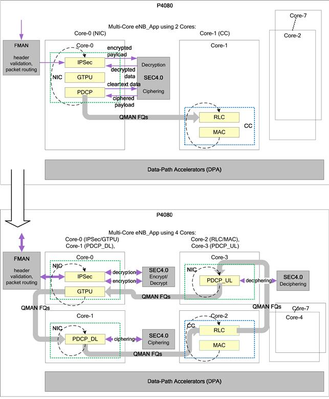
Figure 34: 4-core distribution of eNB_App.
To move to the 4-core solution proposed above, the processing load was balanced across the four cores of the P4080. The IPSec and GTPU functionalities were kept on Core-0, while the PDCP DL and UL functionalities were atomized into separate functions – process_sdu_PDCP_dl and process_sdu_PDCP_ul. Their execution was then transferred to Core-1 and Core-2 respectively. The execution of the RLC and MAC modules was directly moved to Core-3 (Figure 35).
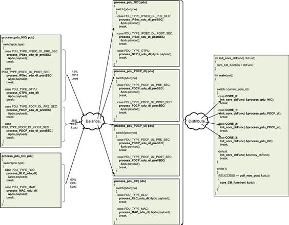
Figure 35: Using atomized modules for load-distribution.
The code modularity and the process of distribution of various sub-modules on cores can be improved through a framework. This framework among other module-specific information contains the binding of each sub-module with the specific Core on which it has to be executed. This greatly simplifies the task of rearranging the arrangement of sub-modules across cores.
As shown in Figure 36, a global list of sub-module initialization information is maintained in the Module Information Table. The designated Core and Pool Channel are maintained as parameters of the sub-module initialization information. During the Application initialization, the framework checks which sub-modules are to be executed on the current Core; the framework then requests QMAN to only dequeue data from FQs that are destined for the specific Pool Channel.
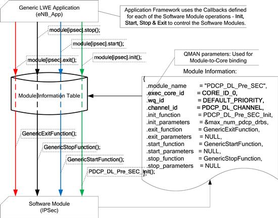
Figure 36: Using the module information table for distribution.
The code snippet in Figure 37 shows how the usage of the Module Information Tables simplifies the initialization routine of the software modules. Such an abstraction also brings in a desired amount of flexibility which permits the application to remain unchanged even when modules within the system are re-arranged or the underlying platform is changed. This greatly reduces the maintenance and adaptation burden which is common while developing software which is meant to be scalable and deployable across multiple SoC variants.
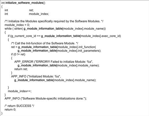
Figure 37: Initializing software modules defined in the module information table.
The actual binding of each sub-module to a specific Core is done using QMAN Pool Channels (the usage of QMAN for Communication is explained in greater detail in the following section). Each sub-module can be associated with a single Pool Channel, and it is possible for each Core to configure QMAN to de-queue FDs from only specific Pool Channels. Using this associative property, we can bind sub-modules to specific Cores.
Advanced accelerator usage on P4080: practical examples
As part of the migration of the eNB_App from single-core to multi-core (P4080), Step 2 and Step 3 involved leveraging the hardware accelerators available within the P4080 DPAA. The P4080 DPAA was extensively used for the following tasks:
FMAN – Parsing and distribution of Ingress packets, validation of common headers
QMAN – Inter-module communication, context-stashing
BMAN – memory management for data-buffers shared across all sub-modules
The following are some of the examples of using the P4080 DPAA to offload and simplify the eNB_App software:
Figure 38 highlights the interaction between the IPSec module of eNB_App and the FMAN block of the P4080 DPAA.
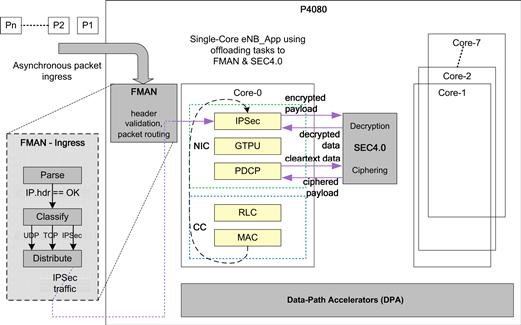
Figure 38: FMAN Usage in packet pre-processing.
The PCD (parse, classify, and distribute) functionality of the FMAN is utilized by the eNB_App to offload part of the packet processing (or pre-processing). Data packets received by the LTE eNodeB are first analyzed by the PCD functionality of the FMAN. The PCD functionality within the FMAN will first parse the incoming packet headers to identify relevant packets. For example, the FMAN will parse incoming IP packets to identify all the header fields of the IP packet. In fact, the parsing functionality will parse the received packet for all the common headers following the IP header as well (for example the UDP headers following the IP header in a UDP/IP packet).
After the packet headers have been parsed, they will be classified based on the values of the packet headers. For example, IP packets whose ‘protocol’ header field has the value of 17 (0x11) are classified as UDP packets. Similarly, IP packets whose ‘protocol’ header field has the value of 50 (0x32) are classified as IPSec packets.
The classified packets can then be distributed according to special rules that can be applied for the header fields parsed earlier. Packet-distribution is done by enqueuing the selected data-packet onto a QMAN Frame Queue (FQ). The QMAN FQs provide a reliable and in-sequence delivery mechanism of the enqueued packets. The packet processing context (for example IPSec module) is the consumer of the enqueued Frames. It is possible to pre-process the packets even further by identifying specific streams within the class of packets.
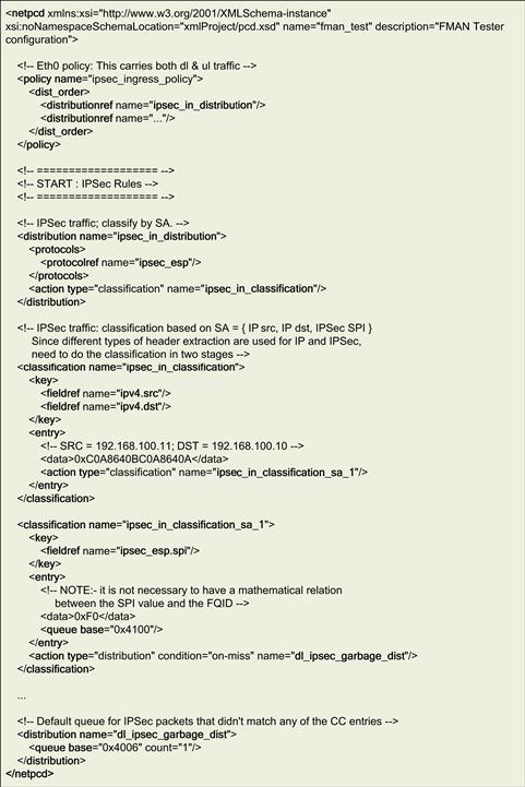
Figure 39: Packet parsing automation using FMAN.
The sample PCD file given in Figure 39, shows how FMAN is configured to parse incoming IPSec packets. The ipsec_ingress_policy first tries to distribute IPSec packets (using the ipsec_in_distribution). The ipsec_in_distribution forwards only the received ESP/IP packets (protocolref name=”ipsec_esp”) for further classification (ipsec_in_classification) to identify the SA(s). If the received packet has an IP source & destination address pair of ‘192.168.100.11’ and ‘192.168.100.10’, then the packet is classified to belong to SA_1; this can be further classified on the basis of the SPI value of the ESP header. If the SPI value of the ESP/IP packet is 250 (0xF0) then the received packet would be placed on the Frame Queue with the FQ Id 0x4100 (for further processing). Any packet which does not have an SPI value of 250 is treated as an unknown packet and forwarded to an FQ reserved for ‘garbage’ data.
Thus, using FMAN, common tasks such as the routing of packets to appropriate modules of the eNB_App can be directly done and the modules as such can be simplified by removing the parsing and routing functionalities that are often associated as part of the SAP (Service Access Point) handling of the module.
The ciphering/deciphering algorithms being repetitive and compute intensive are ideal candidates to be offloaded to a dedicated hardware block. The SEC4.0 block on the P4080 is capable of performing ciphering/deciphering based on SNOW-3G algorithms (which are used in LTE). In order to effectively use the SEC4.0 block for ciphering and deciphering the PDCP module was rewritten. This is in-line with the concept of code-reuse presented in Reuse.
In addition, the SEC4.0 block of the P4080 is also aware of its usage within the scope of LTE. The SEC4.0 block has advanced capabilities to perform ‘protocol-aware’ processing corresponding to the LTE PDCP sub-layer:
• parse the PDCP PDU header to extract information needed for deciphering, and
• build the PDCP PDU header after the successful completion of ciphering
The packets themselves are encapsulated within BMAN Buffers. The BMAN Frame-descriptors (FDs) provide references to the data stored within BMAN Buffers. The FDs allow the data packet to be processed without requiring actual data movement (Figure 40).
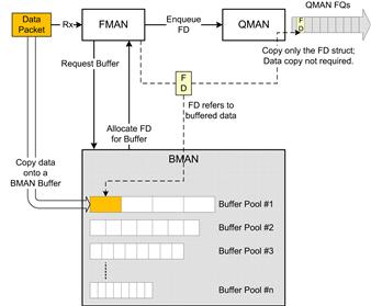
Figure 40: BMAN buffers in FMAN, QMAN interaction.
(Additionally, the FDs provide a uniform interface for both the software modules as well as all of the DPAA modules to access the data held within the BMAN Buffers.)
Figure 41 highlights the usage of the SEC4.0 block for deciphering PDCP payloads.
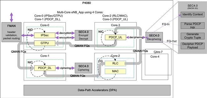
Figure 41: Using the SEC block for SNOW-3G offload.
At the time of initialization of a deciphering context, the SEC4.0 block is configured with a ‘descriptor’ which contains the deciphering context. Additionally, a unique QMAN FQ (FQ-In) receiving the ciphered PDCP PDUs is associated with each aspect of the deciphering context along with a corresponding egress FQ (FQ-Out).
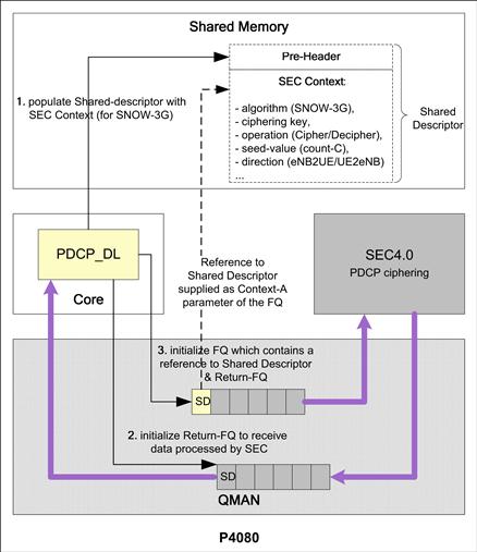
Figure 42: Using the shared descriptor to initialize SEC4.0.
As shown in Figure 42, initializing a context within the SEC4.0 block consists of creating a Shared-Descriptor and a pair of QMAN FQs that are used to send and receive data from the SEC4.0 block. A memory area that is common to the Core as well as the SEC4.0 block is used to maintain the context within the Shared-Descriptor. The ‘FQ-In’ is initialized to contain references to both the Shared-Descriptor as well as ‘FQ-Out’.
Figure 43 describes the algorithm used to initialize the SEC4.0 block in order to establish a ‘security’ context which would be used to cipher (or decipher) packets corresponding to the context. The SEC4.0 block within the P4080 maintains the ciphering context within a shared memory space – the Shared Descriptor. The sequence of steps followed to initialize the SEC context is as follows:
• Step 1 consists of allocating the memory that will be shared with the SEC4.0 block; a BMAN buffer is allocated for this purpose.
• In Step 2, the actual addresses of the start of the Shared-Descriptor and the Pre-Header Descriptors are identified. The Pre-Header Descriptor is used to pass parameters specifically used by the SEC4.0 block, while the Shared-Descriptor is used to pass the algorithm-specific parameters.
• In Step 3, a BSP API is called to construct the shared-descriptor corresponding to the ciphering algorithm (SNOW_F8). The parameters that are relevant to this specific algorithm are supplied to the BSP API which constructs the descriptor which is compatible with the SEC4.0 block.
• In Step 4, the Pre-Header descriptor is updated so that the SEC4.0 block can operate upon the information contained within the Shared-Descriptor.
• Finally, once the Shared-Descriptor has been updated with the ciphering context, a dedicated QMAN FQ is created in Step 5.
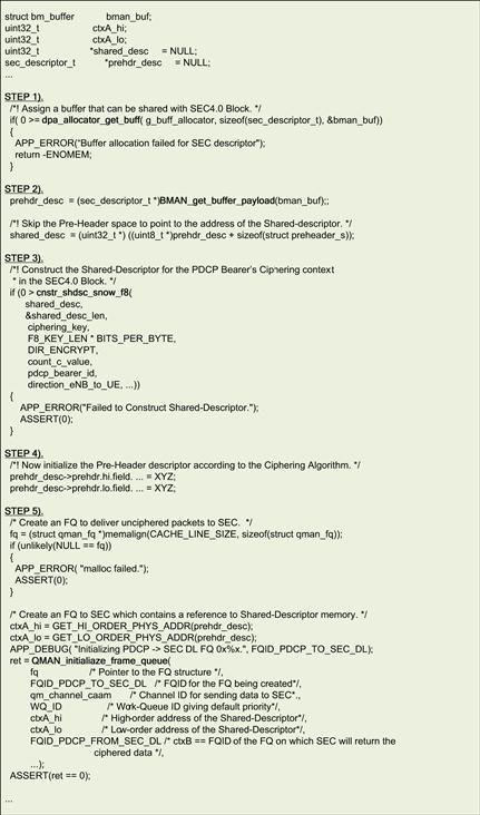
Figure 43: Initializing the SEC descriptor for SNOW-F8 algorithm.
In addition to the default parameters of the function that creates the QMAN FQ, extra information, such as the High & Low-order addresses of the Shared-Descriptor, the specific Channel which is used to communicate with the SEC4.0 block (qm_channel_caam) and the FQ on which the ciphered data is to be returned (FQID_PDCP_FROM_SEC_DL), is provided to the FQ creation API.
Thus, when any data is sent to the SEC4.0 block using the QMAN FQ initialized here (FQID_PDCP_TO_SEC_DL), the SEC4.0 block will use the information stored in the Shared-Descriptor associated with this QMAN FQ, cipher the given data, and return the ciphered data on the return QMAN FQ (FQID_PDCP_FROM_SEC_DL).
When a ciphered PDCP PDU is received, it can be directly forwarded to the SEC4.0 block on the appropriate ingress FQ (FQ-In). The SEC4.0 block will retrieve the deciphering context based on the FQ on which it receives the PDCP PDU. To extract the run-time context information, the SEC4.0 block parses the header of the received PDCP PDU to directly generate the required deciphering context. The deciphered PDCP payload is then returned back to the PDCP sub-module which handles PDCP UL (Uplink) data.
NOTE: This ‘insertion’ of the SEC4.0 block into the PDCP UL processing path requires that the PDCP UL module be split into the pre-SEC and post-SEC functionalities. Thus, the PDCP UL module is further atomized into the PDCP_UL_Pre_SEC and PDCP_UL_Post_SEC sub-modules.
Similarly, in the DL (Downlink) direction the SEC4.0 block can directly receive the PDCP payload. The SEC4.0 block will cipher the PDCP payload based on the stored ciphering context (which gets automatically updated after the ciphering of each PDU). After the successful ciphering of the payload portion of the PDCP PDU, the SEC4.0 block can directly generate the PDCP header as well.
After FMAN processing, the received packet is forwarded to PDCP for the start of downlink (DL) processing in the LTE L2 DP. As part of the atomization activity the PDCP DL processing has been separated into the pre-SEC and post-SEC sub-modules.
In the third phase (Step 3) in the effort to optimize the eNB_App for the P4080 platform, the eNB_App was distributed across the cores of the P4080. This distribution was intended to balance the resource requirements of the various sub-modules of the eNB_App. In addition to this, a new mechanism (as shown in Figure 36) to flexibly configure the sub-module to core association was devised. Using this approach it is possible to support different configurations of the eNB_App with different arrangements of sub-modules across the available cores. This allowed the iterative process of balancing the eNB_App with the aim of maximizing its performance.
As mentioned in Step 3: Distributing the application on the multi-core SoC, QMAN FQs were the primary inter-module communication mechanism.
The use of QMAN FQs permitted a rapid conversion of the Single-core Application to a Multi-core Application.
Each FQ is associated with a Channel and a Work-Queue (WQ) within that Channel. The Channel associated with the FQ is used to define the consumer(s) of the FDs enqueued on the FQ while the WQ is used to assign a processing priority to the FQ.
There are two types of Channel – Direct Connect (DC) Portals and Pool Channels.
DC Portals are Channels that are associated with specific hardware (HW) blocks. Each HW block has one DC Portal associated with it. As a result only the HW block that owns the DC Portal can dequeue FDs that have been enqueued on an FQ associated with that DC Portal.
A Pool Channel, as the name suggests, permits the FQs associated with the Pool Channel to be consumed by a pool of consumers. Any of the Cores can be associated with a Pool Channel and a Core may be associated with multiple Pool Channels (Figure 44).
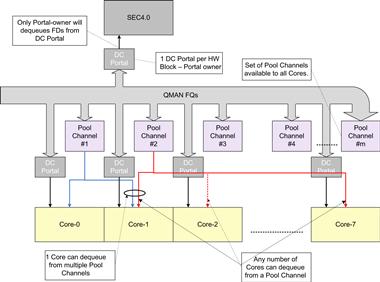
Figure 44: Usage of QMAN for IPC.
The flexibility imparted by the Pool Channels has been extensively used in refactoring the Application from Single-core to Multi-core.
The QMAN FQs can be initialized to carry out queue-based IPC between the various modules (hardware blocks and software modules) of the P4080 SoC. Each QMAN FQ that has to be used needs to be initialized before use. QMAN FQs can be used to either connect to a DC Portal, or a Pool Channel. DC Portals are hardwired and terminate on specific Hardware Blocks of the P4080 SoC – for example, the ‘qm_channel_caam’ is used to connect to the Security Engine block.
Setting up a QMAN FQ for IPC consists of two basic operations – qman_create_fq and qman_init_fq. When creating a QMAN FQ it is given a unique identifier – the FQ-Id, along with parameters which govern the FQ operation such as whether it terminates on a DC Portal or whether it will be used to receive BMAN buffers from a Hardware block, etc. Once a QMAN FQ is successfully created, its behavior and context can be initialized. The QMAN FQ context consists of information such as the Channel and Work-Queue with which the QMAN FQ is associated, any hardware or software contexts that are associated with the FQ, and whether the stashing feature is to be used or not (Figure 45).
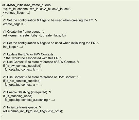
Figure 45: Initializing a QMAN frame queue.
As previously mentioned, the end-points of the QMAN FQ are decided by the Channel that it is associated with. While DC Portals are associated with hardwired end-points, the QMAN FQs associated with Pool Channels can be handled by any combination of cores. To process QMAN FQs associated with a Pool Channel on a specific Core, the Core must specifically instruct the QMAN to dequeue Frames that have been enqueued onto that particular Pool Channel. The qman_static_dequeue_add API is used to register the Pool Channels that would be de-queued on a particular Core (Figure 46).
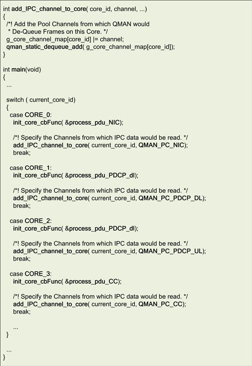
Figure 46: Setting up QMAN to restrict FQs per core.
Each of the software modules are associated with single and independent Pool Channels – QMAN_PC_NIC, QMAN_PC_PDCP_DL, QMAN_PC_PDCP_UL and QMAN_PC_CC. As shown in Figure 46, this allows the software modules to be easily distributed across Cores by:
1. Initializing the QMAN FQs that receive data for each software module to be associated with the specific Pool Channels assigned to that module.
2. Adding the specific Pool Channel (associated with the software module) to the list of channels that the QMAN will dequeue only on the Core assigned to run that software module.
As mentioned earlier in the section on multicore considerations, to modify the Single-core Application to run across multiple cores, it is essential to ensure the proper Distribution & Balancing of the sub-modules.
The example illustrated in Figure 47 shows the distribution and balancing of the PDCP_UL module across the cores of the P4080.
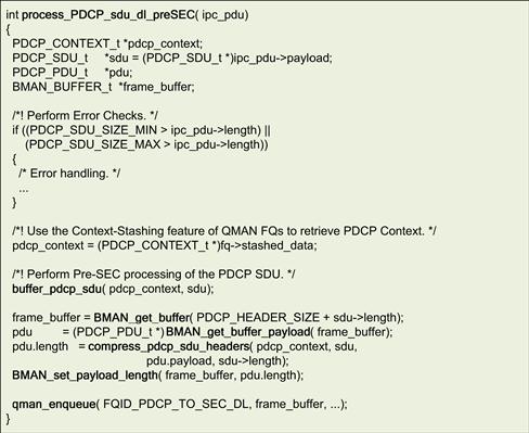
Figure 47: QMAN FQ being used for IPC.
In this example using the three Cores, both PDCP_DL and PDCP_UL modules have been configured to execute on Core-1. This is made possible by configuring QMAN to dequeue FQs from pool-channel PDCP_UL_CHANNEL on Core-1. This module configuration related to the channel used by the module is maintained within the Module Information Table.
Figure 48 illustrates an example of distribution over four Cores, in which PDCP_DL is still configured to execute on Core-1, while, the PDCP_UL module has now been configured to execute on Core-3. This can be achieved by modifying the configuration of the PDCP_UL module in the Module Information Table. The configuration of the PDCP_UL module is modified so that QMAN FQs from pool-channel PDCP_UL_CHANNEL will now be de-queued on Core-3 (instead of Core-1 as shown in Figure 49).

Figure 48: QMAN Pool channel used to execute PDCP_UL on core-1.
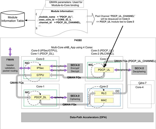
Figure 49: QMAN pool channel used to execute PDCP_UL on Core-3.
Tips and tricks
A majority of Multi-core SoCs contain various hardware accelerators which assist in implementing the target uses. Usage of these hardware accelerators not only improves the performance of the applications that run on them but also reduces the development and test effort to develop the application.
A good example of the leveraging of such accelerators has been the leveraging of the SEC4.0 block described in the previous section.
While distributing software modules across the multiple Cores, care must be taken to ensure that data-structures are optimized for such an operation. The sharing of data-structures across multiple Core must be minimized as far as possible – this may require the original data-structures to be redesigned so that modules running on different Cores may concurrently access their respective data with minimal (if any) need for synchronization.
When moving from Single-Core to Multi-Core the use of global variables should be carefully analyzed. The use of global variables must be checked against race-conditions and synchronization errors.
A good practice is to minimize the usage of global variables. If they are at all required, they should be declared as volatile whenever the value of the variable is likely to change. For all other purposes, they should be treated as constant variables. If there are variables which have scope that is global to each Core, then these could be declared as an array of global variables, with each index representing the Core-specific value of the global variable – access mechanisms to access Core-specific global variables may be defined for accessing such variables (Figure 50).
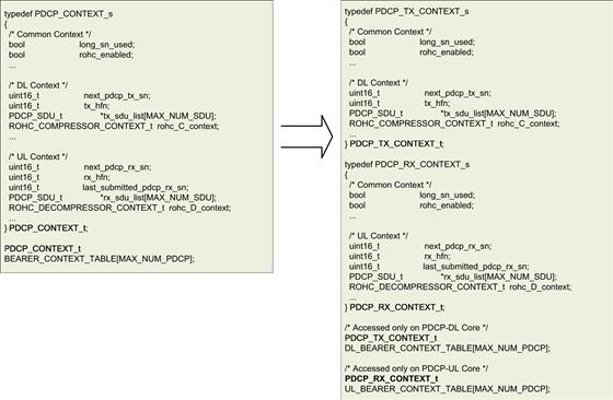
Figure 50: Example of data distribution.
In the example shown in Figure 51, the scope of usage of the pointer to the currently active PDCP context has been modified so as to avoid race conditions in cases where multiple Cores could be used to simultaneously process PDCP SDUs. As can be seen in the example, the scope of the variable identifying the PDCP context has been reduced from global to local. Thus, when PDCP executes on multiple-cores, the race condition involving the correct PDCP context using which a PDCP SDU was processed is overcome.
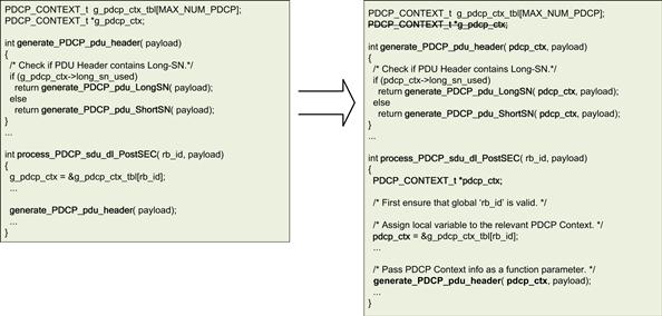
Figure 51: Example of removing unnecessary use of global variables.
When calling nested functions, care must be taken to limit the number of parameters that are being passed as formal parameters.
A good programming practice is to limit the number of formal parameters passed to functions, as too many formal parameters will lead to data being pushed to the stack. The exceptions to this are the leaf-functions where the compiler may optimize the formal parameters by retaining them as register variables. Even in such cases, excessive parameter counts have a detrimental impact on the performance.
Variables that are used locally within functions should be initialized as close to the piece of code where they are to be used as possible. This allows the variables to be retained as register variables and the structures could be retained within the caches (Figure 52).
Figure 52: Localization of variable usage.
In frame-based protocols (such as RLC/MAC) where a new PDU may be formed from multiple SDU segments, using DMA to copy the data from the various SDU segments may be more efficient than using MEMCPY. In such a case, the individual SDU segments may be identified and their memory locations and sized maintained in data-structures until the final PDU formation process. At the time of PDU formation, the memory offset and segment lengths can be given to the DMA controller which would be able to form the PDU more efficiently.
Conclusion
This case study demonstrates that a well defined and systematic development strategy enables a successful migration of embedded application solutions designed for single-core SoC to a new generation of high performance multi-core SoC. The migration path, discussed in Section 6 of this case study, is equally valid when the embedded applications are designed directly on the multi-core platforms. When the applications are directly being designed on the multi-core platform, the initial starting point can still be the single core of a multi-core SoC.
Thereafter, this solution can be incrementally scaled to use the various available accelerators and finally the various available cores for higher system performance. Lastly, the science of developing the software on high performance multi-core platforms is still evolving and the engineering teams need to adopt an incremental development approach that focuses on the highest quality of software to mitigate the risks introduced by a new technology paradigm.
Abbreviations
| 3GPP | 3rd Generation Partnership Project |
| BMAN | Buffer MANager |
| CPU | Central Processing Unit |
| DL | DownLink |
| DPAA | Data-Path Acceleration Architecture |
| FMAN | Frame MANager |
| FQ | Frame Queue |
| GTPU | GPRS Tunneling Protocol – User plane |
| IPC | Inter-Process Communication |
| IPSec | IP Security protocol |
| LTE | Long Term Evolution |
| MAC | Medium Access Control |
| QMAN | Queue MANager |
| PDCP | Packet Data Convergence Protocol |
| RLC | Radio-Link Control |
| SEC | SECurity Engine |
| SoC | System on a Chip |
| UL | UpLink |