CASE STUDY 6
DSP for Software Defined Radio
Introduction
The idea behind SDR (software defined radio equipment) is to have a multi-band, multi-standard terminal that can adaptively select the best communication stack available to establish a successful connection according to the QoS of the demanding services.
We can look at SDR from two perspectives: the mobile terminal and the base-station. The mobile terminal has multiple communication stacks implemented, but at any given time, it should use only one of these, according to a given criterion.
The criteria, depending on the application, may be:
• The terminal must provide measurements on each of the candidate bands
• It then chooses the network that offers the best link conditions according to physical layer measurements: received signal power, signal to noise + interference ratio
• As a boundary condition, the terminal must select the operating technology in a region when usually only one technology is available from a certain carrier
• The terminal should choose the network that provides the best throughput according to the individual link quality and to its throughput requirements.
• For example services cost (e.g., Always choose WiFi against 3G for data services)
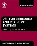
In both cases, measurements are done at the physical layer level (L1), but decision is taken at an upper layer. In Figure 1 a mobile terminal monitors reference signals transmitted by one or several base stations on different bands, different technologies. Once the band is swept, L2 of the terminal takes the decision and chooses one available resource.

Figure 1: Establishing connection at layer 1 for a SDR.
This is the case of a smart phone that can access the Internet via multiple available technologies: 2.5G EDGE, 3G UMTS, 3G+ HSPA, 4G LTE (soon to come), and WiFi. Only one of the available technologies is used at any given time for data transfers.
Right now, switching among these technologies is done at a higher layer in the protocol stack. SDR equipments tend to lower down the level of decision, into L2, according to fast L1 measurements. This will massively reduce the overhead of using the entire protocol stack. Also, the tendency is to use the same processor for all L1s, which is something most of the state-of-the-art smartphones do not currently support. They usually have different ASICs for different standards of communication (especially for WiFi and 3G). Even though at a given time, only one will be functional, area will be used to support all kinds of technologies. And most likely power consumption will not be optimized due to this. Using only one processor may lead to a significant resource save because of a very simple reason: resource reuse. A simple example can be stated. If we have a terminal that supports LTE, WiFi and WiMAX, then we can share the FFT resources, which are extensively used in all three cases.
On the base station side, we can have two cases. Consider a carrier network that supports any 3GPP communication technology from 2.5G to 4G (EDGE to LTE). This can be ensured at first glance by using several base stations, one for each supported technology. It is like having three different networks (one for EDGE, one for UMTS, one for LTE) and the mobile terminal will connect to any of these three. It is a rough solution to support all possible cases. An elegant solution would be to have one base station supporting all three standards, without considering additional network equipment, in a converging network architecture, using the same RNC (Radio Network Controller). Most of the standards are built so that time coherency is kept on the network architecture level. Therefore, support of a newer version of the specs can be done without changing the architecture.
We will focus in this chapter on the base station, since we find it a more general case. While the terminal has to support one technology at a time, the optimum one that fits the needs, the base station must operate with all sorts of stations simultaneously: some old terminals supporting only EDGE, some newer with UMTS capabilities, and some state of the art smartphones, equipped with LTE transceivers. Thus, designing a multi-standard base-station becomes a hot topic of today’s telecom industry.
Functional architecture of a base station
General partition
The general partition of the protocol stack for software defined radio equipment is presented in Figure 2.
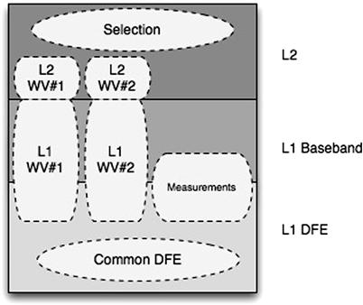
Figure 2: Lower protocol stack partition for a SDR.
The common DFE is responsible for up and down conversion, up/down sampling, predistortion, crest factor reduction. The former two operations may strongly depend on the technology used and may not be part of the common block, according to design. This is mainly because of the sensitivity of multi-carrier transmissions to produce spikes in the time-domain signal and affect the PAPR (Peak to verage Power Ratio). To some extent, this is fixed in the LTE uplink transmission, where SC-FDMA is used instead of OFDM.
The equipment includes several waveform generators (WV), with appropriate Layer 1 (L1 WV #k) and Layer 2 (L2 WV #k) implementations. There are some measurement modules, so-called spectrum sensing in SDR terminology. These measurement modules monitor the energy of the received signals in different bands, on different standards.
Reports are forwarded to upper layers that eventually take the decision of initiating network entry on a specific technology and on a certain band. If already connected to a network, the upper layers may take the decision to switch to a new resource, in order to maximize either link or capacity, as stated previously.
LTE eNodeB
The functional block diagram of an LTE eNodeB transceiver is shown in Figure 3.
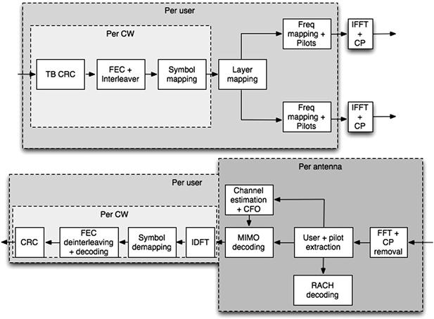
Figure 3: Simplified LTE eNodeB transceiver.
The transmitter processes independent bit streams, called codewords (CW). These will be transmitted using different virtual antennas. It is up to the configuration to map these virtual antennas onto physical antennas. Also, generalization of this principle may lead to a precoding that spreads the codeword energy on all the antennas, thus forming a virtual antenna beam on which this CW is sent on air. Each codeword has its own bit processing part, consisting of CRC appending, FEC encoder (either convolutional or turbo), rate matching and interleaving. The so-formed bits map symbols from a constellation (QPSK, 16-QAM, 64-QAM) and are mapped onto the antennas, as specified, on specific time/frequency resources, called resource elements (RE). At this point, reference signals are added. These can be either dedicated or common per all users. OFDM modulation is further applied, using an IFFT transformer and a cyclic prefix (CP) padding.
On the receive side, the inverse operations are applied in general. OFDM decoding occurs, by removing the cyclic prefix and then using an FFT transformer. Each user is then extracted from the time-frequency grid. The reference signals are used to estimate the channel and any carrier frequency offset (CFO) per receive antenna. These channel estimates are further used for MIMO decoding, where a general ML decoding algorithm should be applied. In practice, these receivers use either a quasi-ML approach (such as sphere decoding) or a sub-optimal receiver, as in the case of MMSE (Minimum Mean Squared Error). Over uplink, LTE uses SC-FDMA (Single-Carrier Frequency Division Multiplexing). Data is not exactly mapped in frequency, as is, but rather spread at transmission, using a DFT transform. Hence, at the receiver, a despread IDFT operation occurs, followed by a symbol demapping, usually with soft bit outputs, called LLR (Log-Likelihood Ratio). Bit processing at the receiver then goes on in the exact manner as in the transmission, with de-interleaving, channel decoding, descrambling, and CRC check. If multiple retransmissions are employed, such as in the case of HARQ (Hybrid Automatic Repetition Request), the combining is done within the decoder.
UMTS and HSPA NodeB
3GPP WCDMA standard is backwards compatible, e.g., the same L1 implementation can host R99 (UMTS) and HSPA (and HSPA+) transport channel implementation, since they are both based on Direct Sequence – CDMA (DS-CDMA).
In Figure 4, we have a general block diagram of a UMTS/HSPA transceiver.
Figure 4: General block diagram of a UMTS/HSPA transceiver.
Over DL (downlink), each transport block is encoded and mapped onto symbols from constellation (QPSK, 16-QAM). Then more transport blocks are concatenated in a physical channel. This physical channel is spread with a channelization code and then scrambled using the cell primary scrambling code. On UL (uplink), each user has its own scrambling code. First, NodeB detects the fingers of the user, i.e., the propagation paths, in the attempt to coherently combine all propagation paths. This is done via a path searcher, which detects propagation paths, delays, and magnitudes. Each finger is descrambled and despread. Then all the fingers are coherently combined in a Rake receiver, using the channel coefficients, as provided by the channel estimator. The RACH channel is not explicitly shown here, but it uses the same architecture.
Joint architecture
Solution for a hybrid (e)NodeB would be to use a baseband processor (Figure 5) with as much processing power, in order to be able to:
• carry the throughput from/to L2 for both standards
• carry the samples from/to RRH (Remote Radio Head) for both standards
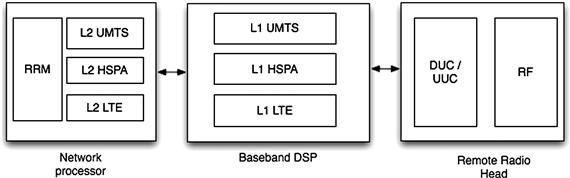
Figure 5: Hybrid transceiver (L1 + L2 + RF).
These requirements lead to constraints on the design of the platform. The need for concurrent tasks, corresponding to different and independent standards of communication, raises the idea of multicore processing. A single core cannot be shared among multiple real-time flows. Instead, multiple cores can do that. These cores work in parallel and raise the MIPS figure by a factor roughly equal to the number of processors. Increasing the number of cores leads to increasing the overhead required to manage them (and possible bottlenecks to the shared resources (memory, I/O, accelerators)). The degree of improvement is therefore not exactly proportional to the number of cores. There are an optimum number of cores that provide optimum performance / cost + power ratio. Nowadays, it is mutually and generally agreed that this number is around 6.
Apart from multicore processing, processing power should come from hardware accelerators. It is bad design to block one core with repetitive operations, occurring on a symbol/chip/packet basis. Instead, if such operations occur on a periodic basis, a dedicated circuit can be used for that. Repetitive operations in the case of communication systems at the L1 level may consist of:
Processor
A case study for the baseband processor is Freescale’s MSC8157. This is a six-core (SC3850) processor, whose unique powers derive from the HW accelerators on the chip. These are grouped into a single co-processor, called MAPLE. A block diagram is shown in Figure 6.
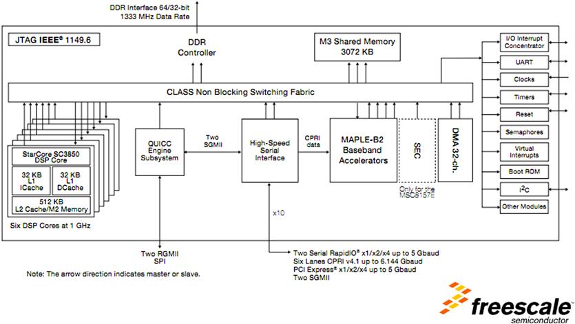
Figure 6: MSC8157 block diagram.
MAPLE comprises several hardware units, called Processing Elements (PE), specialized in typical operations or series of operations likely to be performed on a large scale in communication equipments.
A list of the PEs that may be used in a system and their use cases is presented in Table 1.
Table 1: MAPLE coprocessor processing elements.
| PE Name | Application | Use Case |
| CONV PE | LTE + UMTS + HSPA | Used for correlations (RACH channel, path searcher) |
| EQPE | LTE | Equalizer using either Zero Forcing, MMSE or Maximum Likelihood for MIMO |
| FTPE | LTE + UMTS + HSPA | FFT 128…2048 points used for OFDMA DFT up to 1200 points, used for SC-FDMA Used for fast correlations using CONV PE |
| CRC PE | LTE + UMTS + HSPA | CRC Check for uplink and CRC insertion for downlink Several polynomials used for CRC16, CRC24, CRC32, CRC16, CRC12, CRC18 |
| eTVPE | LTE + UMTS + HSPA | Channel decoder for turbo and convolutional codes Soft or hard Several polynomials supported |
| DEPE | LTE + UMTS + HSPA | Turbo encoder |
| CRPE | UMTS + HSPA | Chip-rate processor Spreading and despreading with spreading factors up to 256. |
Software architecture
When using multiple cores, care must be taken to design the software architecture in order to fully benefit from the processing power provided by the number of cores.
In Figure 7, the control plane is described. Each L1 accesses shared resources, such as cores, accelerators, and memory. Access to the cores is achieved through a real-time operating system. The scheduler of the operating system schedules and dispatches jobs to cores in different ways: dedicated or based on the core load at a given time. Triggering the job execution can be done in several ways, based on different criteria:
• Some jobs should be executed once they are in the queue rather than the others.
• Jobs that require reading from or writing to a buffer may need to be executed with higher priority to ensure that buffers are not filled up.
• Some jobs need to be executed at precise times (synchronous operations).
• Such jobs are the ones involving transactions at the synchronous interface (CPRI)
• Jobs should be executed only after previous jobs in the signal flow have been executed.
• Example: in WCDMA, a chip-rate processing may only occur after each open and planned physical channel has been built at the symbol level.
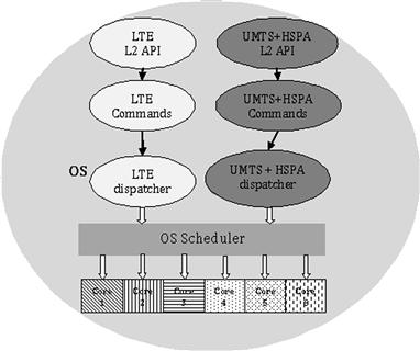
Figure 7: Control plane of the SW architecture.
An example of a job diagram for WCDMA case is depicted in Figure 8.
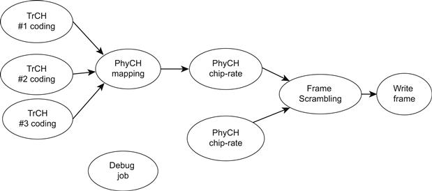
Figure 8: Possible job dependence for WCDMA transmitter.
In Figure 8, TrCH#k coding are jobs that take care of encoding a transport channel. These are all command driven jobs. It means that their scheduling is the result of a previous command issued by a higher layer for the current frame. PhyCH mapping takes care of all the processing described in Figure 4 for a physical channel comprising three transport channels. This job should be executed as early as possible, but only after all TrCH #k jobs have been executed. Hence, this job has in fact 3 predecessors. Each physical channel is then processed as per CDMA flow, by passing through a spreading operation. This is also dependent on the mapping job having been completed. Frame scrambling can occur only after all physical channels have been spread. This job then conditions the execution of the job of writing all the samples to a synchronous or asynchronous interface to radio. This job should also be triggered by a timer that indicates when these samples should be presented to the interface. No matter how early or fast frame scrambling has been performed, a subsequent job will also wait for the right time to send samples further. In addition, a debug job, logging different events can be introduced, usually with lower priority, as real time is not a real requirement for this. Scheduling should be done making sure that, in the worst case, in the highest load scenario, a frame can be completely processed once all commands have been issued, until the samples have to be pushed to the radio. Any of the jobs described above can be executed on the core or on an accelerator.
Such an approach ensures that a various number of L1 independent paths may access shared resources. The goal of the scheduler and of the high-level design is that the total combined processing power of the cores and accelerators covers the total needs of the arithmetic operations inside the L1 paths, minus a multicore scheduling penalty. Such a flexible and scalable approach ensures an easy design of a complex multi-standard and multicore architecture.
Conclusion
Digital signal processing has become a powerful premise for the world of wireless communications. All the latest technologies, including OFDM, CDMA, and SC-FDMA, that represent the main foundation of the 3G-4G networks, such as HSPA, LTE, or WiMAX, are now made possible by the high density of digital algorithms that can be squeezed into a small, low-power chip. On top of that, additional signal processing techniques, such as beamforming or spatial multiplexing, have contributed to the achievement of throughputs of hundreds of Mbps and spectral efficiencies of tens of b/s/Hz. Also, some other complex algorithms that can be found in channel estimators, equalizers, and bit decoders allow all these techniques to operate in a tough radio environment, including in non-line of sight communications with high mobility, even at large distance.
Large-scale integration allows a handheld device to include a multi-standard terminal, compliant with a large variety of wireless standards. Think about a smart phone that now conveniently chooses the best technology for data and voice transmission, according to its service needs and to the channel conditions. This is why your smart phone can connect to the BTS through GSM, EDGE, UMTS and soon, LTE. At the same time, it has capabilities for Wi-Fi, Bluetooth, and GPS connections, all these in a very small terminal, with good battery life. In the future, this service selection and multiplexing will only be defined through software. Without digital signal processing, relying solely on analog components, there would be no possible way to achieve such performance. Right now, the analog part in a transceiver is losing its pace in front of the digital part. More and more operations are performed in the digital part, including filtering, up/down conversion, and compensations of the distortions produced in the analog chain, at a smaller price and with better performances. Moreover, it is expected that the analog part will be completely displaced in the future, with the help of high-speed A/D and D/A converters, so that the digital transceiver will be glued directly to the antenna. This part is called front-end in a transceiver and while some 10 years ago it used to be completely analog, it is becoming more and more digital.