Chapter 4. Getting Started with Design
This chapter introduces the many kinds of thinking involved in the design process, by taking you through the steps of designing a very simple bench with AtFAB joinery. While showing key steps and decisions in a design process, this exercise will also familiarize you with how to work within AtFAB’s organized system of joinery, structures, programs, and assemblies. AtFAB was always intended as a starting point for design, which we or anyone could take further. After completing the bench, you’ll have the skills to modify the projects in this book and enough knowledge to start designing completely new pieces that suit your own needs.
When we designed each new piece of AtFAB furniture, we didn’t literally start with the sniglet and work our way up. Rather, we looked to a particular need or use, like the need for a sturdy worktable or enclosed storage, and designed a piece to fulfill that need. To streamline our decisions, we worked within the AtFAB system, which had already figured out the hard stuff like joinery, structures, materials, and fabrication. Instead of constraining, a system frees you up to focus the design process on elegantly integrating functional needs with form, details, and proportions.
This chapter uses techniques with SketchUp to design an object in three dimensions, which will be fabricated as flat 2D parts, and then cut and assembled. You’ll create a basic 3D model for a bench, with integrated CNC joinery. While guiding you through an approach for solving a design problem, the process, concepts, and modeling techniques practiced here can be applied to projects throughout the book. We encourage you to find ways to hack each 3D file, whether by modifying overall dimensions to widen a chair or by pushing/pulling connections in a cabinet to add another shelf. Once you understand the principles of modification, we believe that you will soon want to design your own pieces from scratch!
Define a Project Program
As you embark on a design project, whether furniture or anything else, it’s essential to first research your design program (introduced in “Programs”). A program starts with having a defined need that a design must address. In this exercise, the need that you’ll fulfill is a bench that seats two people. While you already understand the basic program for a bench is seating, you’ll also want to identify more detailed features like ergonomic dimensions and key proportions. The more knowledge you have about the function and context of the thing that you are designing, the better the design will ultimately be.
Ergonomics
If you’re designing a custom piece of furniture for your personal use, you could simply take your own measurements and use them as the basis for your design. However, because this bench seats two people, and might be used by others besides yourself, it helps to think in more universal terms. Because you can’t anticipate the comfort of every individual who may use your bench, you can rely on ergonomics and design standards (see Appendix A) to ensure that it will accommodate the greatest range.
- Consider the following:
-
-
How long does a bench need to be to seat two people?
-
What height and depth are comfortable?
-
- Dimensional requirements:
-
-
General ergonomic standards suggest that a two-seater bench needs to be about 48″ long, and for comfort should be about 18″ deep and 18″ high (1220 mm × 450 mm × 45 mm).
-
Fabrication Constraints
Other variables that will impact your design are the structural capabilities of your material, as well as the CNC machine size, end mill diameter, and stock material size and thickness. Like other AtFAB projects, the stock material and machine dimensions are already determined. We’ll use 4′ × 8′ sheets, with a nominal material thickness that is ¾″. Our end mill diameter will be ¼″. We can safely assume that our optimal bench dimensions will easily work within these constraints.
- Consider the following:
-
-
How big is my material?
-
How big is my machine?
-
- Dimensional limits:
-
-
Machine and material size are both 4′ × 8′.
-
However, there are numerous other program requirements that you might want to research prior to jumping into the design process of a project. “Develop a Program” will elaborate on these additional considerations that your design program might also include.
File Setup For Design
Chapter 3 introduced techniques for using layers, components, and groups to keep your work organized. Setting up your CAD workspace, using layers that facilitate the design process and anticipate fabrication, makes it much easier to focus on your project.
This exercise expands on that organizational logic, as it walks you through the design process. As before, you’ll begin by setting up your SketchUp file and environment—or mise en place—to keep your work organized throughout the design and fabrication process.
Layer Naming Conventions
In Chapter 3, you started with a finished design and then created layers for flattening the parts and preparing their profiles for toolpathing. You will employ those same layers in this exercise. Since you are designing the object itself in this exercise, you will also use several additional layers. The following is a comprehensive list of the layers and a bit more background on the role each one has in the overall workflow:
- Working layer
-
Layer0 is SketchUp’s special default layer. Use this layer as your working layer to create preliminary 3D bench elements, and develop the design. The working layer is the looser, sketchier layer where you explore ideas and model preliminary concepts at different stages of the design process. As your design becomes more defined, you can place elements onto the modeling layer and begin working there. Later in the process, you can always go back to this layer when you need to sketch. See SketchUp Layers: Sacred Layer0 for more info.
- Modeling layer
-
000_bench model is where you’ll place the finalized 3D model of your bench.
- Flattening layer
-
000_bench flat is used for flattened 3D parts, configured into a cut sheet, so they can ultimately be cut on a CNC router.
- Underlays
-
000_bench under is a layer for spatial or graphic elements like guidelines, reference points, boundaries, or objects that are critical to the design process, but not part of the design itself. On the underlay layer, place things like the material boundary, critical ergonomic dimensions, center lines, or a module for spacing hardware or joints.
- Temporary layers
-
Create temporary design layers with a separate prefix, putting them at the end of the list. You can add (and delete) temporary layers (like zzz_stock, zzz_massing, zzz_sophie, zzz_storage), using them to “store” modeled objects during the design process. Objects placed on these layers are not part of the actual design and also aren’t part of the machining workflow. However, they are essential 3D elements that you use in the process of creating the design. Put items like the bench massing, 3D stock material, or the sniglet outline onto this storage layer. Turn them on and off as necessary.
- Cut layer
-
000_bench cut contains vector lines from the flattened parts that form the basis for CNC-able cut files and your toolpath layers.
- Toolpath layers
-
If you’re planning to go beyond this exercise and machine your bench, you’ll need to add toolpathing layers for profile toolpaths and holes (profile inside, profile outside, and holes). The same goes for adding pockets (pocket 1, pocket 2) and for any decorative engraving you may wish to incorporate (text / etch).
Create File, Add Layers
-
Create a new SketchUp file. You can design in either inches or millimeters, whichever suits your workflow best.
-
Activate these window palettes:
-
Window→Entity info
-
Window→Layers
-
Window→Outliner
-
Window→Components
-
-
Set up your layers. Add the modeling and flattening layers:
-
000_Bench model
-
000_Bench flat
-
A prefix, like 000, allows you to easily sort and organize your layer list as you work. You can easily change the prefix numbers to move layers up or down in SketchUp’s layer palette.
-
Add the reference layer:
-
000_Bench under
-
-
Add temporary layers:
-
zzz_massing
-
zzz_storage
-
zzz_sophie (scale figure)
-
zzz_stock
-
-
Optional: Create the cut file and individual toolpath layers:
-
000_Bench cut
-
000_Bench_profile inside, layer color green
-
000_Bench_profile outside, layer color blue
-
000_Bench_holes, layer color red
-
000_Bench_pocket side 1, layer color orange
-
000_Bench_pocket side 2, layer color yellow
-
Assigning colors to each toolpathing layer in the SketchUp file will help when importing the file into VCarve. Associating toolpathing layers by color helps you visually differentiate the profiles and accurately and efficiently assign toolpaths in VCarve.
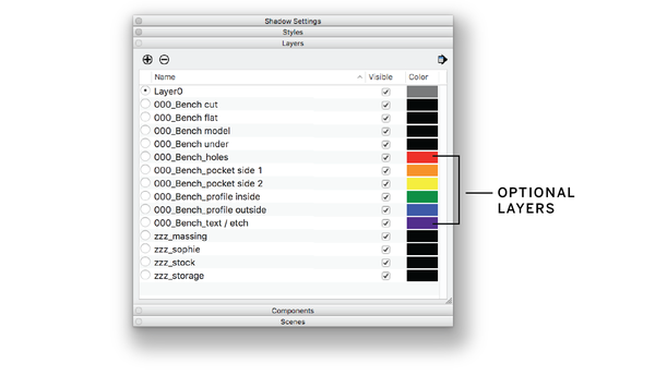
Figure 4-1. Detail of the layer palette, Layer0 is selected
Draw the Cut Sheet Underlay
-
Make Layer0 the current layer.
-
Draw a two-dimensional 4′ × 8′ box (1220 mm × 2440 mm × 19 mm) on Layer0. This box (shown in Figure 4-2) is an example of an underlay. It represents the boundaries of a plywood sheet. It also orients you to the scale of the material relative to the size of the bench and its individual parts.
-
Group the box and then move it to 000_Bench under. Now that it’s on its own layer, you’ll be able to turn it off while you work.
Don’t omit this step. Besides serving as a useful underlay, this box is ultimately used to set up the cut file (explained in Chapter 3) and will be imported into VCarve. It also serves as a reference for scaling and troubleshooting, and will be quite helpful for comparing the size of your design relative to the size of a cut sheet.

Figure 4-2. Underlay that represents a plywood sheet, used to lay out cut file
Massing Model and Stock Material
In the earliest stage of designing, it helps to start with rough, abstract elements, and then develop the design by gradually going into greater and greater detail. In this section, you’ll make the first move by creating a massing model—an abstracted solid model of the object you’re making—in this case, a bench.
As you first make this rudimentary, three-dimensional massing block, use your program research as a starting point. Dimensions derived from general ergonomic standards for a two-seater bench are 48″ long by 18″ deep and 18″ high (1220 mm × 450 mm × 450 mm).
You’ll also model a standard sheet of plywood, or material stock. You’ll use this stock as the source for creating every bench part. By modeling your bench parts from copies of this stock, you’ll ensure that each has a consistent material thickness.
You’ll use ¾″ as the material thickness of your stock. This is a standard nominal thickness, referred to as the variable TNOM, and used throughout this book. Chapter 5 delves into TNOM and working with sheet material thickness.
Imperial to Metric Units
For this exercise, a standard sheet of 4′ × 8′ plywood converts to the metric standard, 1220 mm × 2440 mm. The nominal ¾″ material thickness converts to 19 mm.

Figure 4-3. Material stock alongside bench massing
Create Massing
-
Create a three-dimensional volume that’s approximately 48″ long, 18″ high, and 18″ deep, based on ergonomic standards. This is your bench massing model, it will serve as an envelope to work within as you design your bench.
Model Material Stock
-
Model a sheet of plywood from your cut sheet outline. Use the Push/Pull tool to make the stock a nominal thickness 4′ × 8′ × ¾″, as shown in Figure 4-3.
Push/Pull in SketchUp
To create the massing and stock material, use SketchUp’s Push/Pull tool, explained in Pushing and Pulling Shapes into 3D. As the primary modeling tool used in this exercise, it might help to practice pushing and pulling to familiarize yourself with SketchUp’s interface.
-
Group and then name your newly modeled plywood sheet. Right-click and select Group, and then enter a name in the Entity Info window’s instance field.
Groups and Layer0
Get into the habit of creating all new geometry on Layer0, by ensuring that Layer0 is active (selected). After grouping newly drawn geometries, you can move those object groups onto their respective layers. This practice keeps your model organized and will ensure that later steps in the CAD/CAM workflow go smoothly.
-
Place onto layer zzz_stock.
-
Position the modeled plywood stock adjacent to the bench massing you drew previously.
Standards Versus Proportions
Good design always meets general ergonomic standards, and it also works within manufacturing methods, material limits, and other constraints. After optimizing a design for function and fabrication, you can still find ample room for creative maneuvering during the design process.
When we design, we like to introduce balanced proportions at varying scales within the object, from the overall dimensions down to the smallest joinery details. Proportions are a kind of shorthand that designers use for organizing forms. Proportions, especially those found in nature (like the golden ratio, 1:1.618), bring visual harmony into a design.
The 18” × 18” × 48” massing you just modeled meets ergonomic and fabrication criteria. Lengthening it, so it’s 18” × 18” × 54” (450 mm × 450 mm × 1350 mm) gives it a perfectly proportioned ratio of exactly 1:1:3, without interfering with ergonomic needs or fabrication constraints.
Refine Massing Dimensions
-
Pull one end of the volume, so that the length matches 54″, shown in Figure 4-4.
-
Place the volume, so that the center of its bottom face sits on the origin.
-
Group and then place the massing onto layer zzz_massing by clicking on the Entity Info window and selecting the layer from the drop-down menu. You’ll need the massing for the next step, so leave the layer turned on.
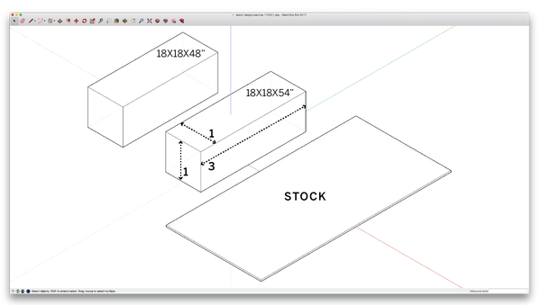
Figure 4-4. Refine bench massing proportions
Schematic Design: Model Parts
Since the actual bench will be fabricated from ¾″ stock material, it’s sensible to use virtual sheet goods of the same thickness to create the bench parts. In this section, you’ll transition your rough massing model into a bench in its absolute simplest form—a long horizontal seat with four vertical “legs” on each side. Next, you’ll copy and modify the ¾″ thick stock, aligning it with the massing block, until you’ve created rudimentary versions of three bench parts.
Copy and Modify Stock, Form Seat
-
Make a copy of the stock. Ensure that you’re working on Layer0 and then paste the stock copy.
-
Explode the copied group by right-clicking and selecting Explode. Then re-group and name it (e.g., bench_seat) in the Entity Info box.
-
Modify (Push/Pull) the length and width dimensions to match the top surface of the 3D bench massing volume to form the bench’s seat.
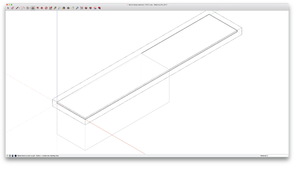
Figure 4-5. Copy and modify the stock to form the seat
-
Align the top face of modified stock with the top of massing. The part should be inside the massing block. Figure 4-5 shows one stock material copy resized to fit the top of the massing block.
-
Turn off layer zzz_stock. You can turn this layer back on, whenever you need to refer to the material stock later in the process.
Create Bench Sides
-
Duplicate the bench seat. Rotate and move the copy to the end of the massing using the Copy/Rotate method discussed earlier (Q → ⌥ Opt ).
-
Modify the stock width/length until it covers the end of the massing (right-click and select Edit Group → Push/Pull).
-
Duplicate the side you created and Copy/Move (M → ⌥ Opt) it into position to form the other end of the bench. The massing block with the stock panels forming the seat and two sides is shown in Figure 4-6.

Figure 4-6. Copy and modify stock to form the right and left sides
When modeling parts, ensure that you only push and pull its length and width. Never modify the thickness of the material stock. It’s critical that each part of your bench maintains a consistent ¾″ nominal thickness, since you are modeling parts that will ultimately be cut from the same sheet of material.
Add Front and Back Parts
-
Make a copy of the seat. You’ll use this copy to form the front of your bench, beginning the “boxing in” process that will create a strong structure.
-
Rotate the seat copy 90 degrees. Move it to cover the “front” of the bench.
-
Create the back by making a copy of the front. Position it opposite the front part to form the bench’s “back.”
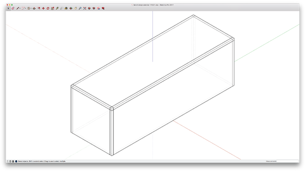
Figure 4-7. Copy and modify stock to form the front and back
Remember that the massing model is the dimensionally accurate “envelope” of the final bench. Place all new bench parts (that will form the actual bench) inside the envelope, aligning the top face of the seat or outside faces of the sides with the face of the envelope. That way your final bench will maintain the correct proportions defined at the beginning of this exercise.
Using Reference Lines
With essential parts modeled and organized into the basic shape of the bench, we can now begin adding finer details to it. Let’s first lighten the bench to make it less boxy in appearance, which has the added benefit of requiring less material. We’ll achieve this by shaping the front, back, and sides to form four conventional “legs” for the bench to stand on.
In addition to the “legs,” we’ll need to shape “beams” across the top of each part. These beams will connect the legs, forming a structural frame that’s strong enough to support sitters of all kinds. In the next steps, you’ll modify these four parts into an upside down “U-shape” that will lighten your bench and maintain its structural integrity.
To model our bench legs, we first need to determine a dimension that is great enough to offer structural support, while preserving our preference for lightness. We’ll choose 4″ (100mm) for both beam depth and leg width, so the entire U-shape is a consistent width. Before you begin modifying the parts, it will help to draw a series of temporary reference lines, which will allow you to model with precision, consistency, and efficiency (Figure 4-8). Later in this exercise, you will use reference lines as you model joinery on every part.
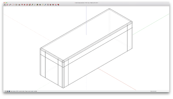
Figure 4-8. Reference lines for beams and legs
Form Legs

Figure 4-9. Beams and legs formed on the front and side
-
Define a dimension for the beam depth and leg width. We’ll choose 4″.
-
Sketch a horizontal reference line along the top outer edge of the front part. move it down 4″ (100mm), keeping the line aligned with the outside vertical face of the part. Similarly, draw a line along the top of a side part, moving it down by the same distance. These two reference lines form what is called a datum, a benchmark that you can use to align or locate other design elements.
-
Draw vertical reference lines along each outer edge of both the front part and one side part. Move these lines 4″ (100 mm) toward the center, keeping them aligned with the outer face. Your model should look like Figure 4-8.
-
Form the front piece into a “U-Shape,” using your vertical and horizontal reference lines for alignment. Select the front, Edit Group, and then use the Push/Pull tool to form the empty void. Exit the group.
-
Make the side piece into a “U-Shape,” using the reference lines for the side piece. Your model should now match Figure 4-9.
-
Copy the front and side parts, and replace the back and second side with copies.
Modeling Feet
Because we’d like our bench to hold up on a variety of flooring conditions, we will add “feet” for extra reinforcement. In addition to protecting the bottom of your bench (as well as the floor) and improving durability, feet are also a critical structural assembly. By joining the long and short sides, they provide extra stability and keep your bench’s structural frame rigid.
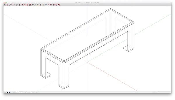
Figure 4-10. Bench with temporary and underlay layers turned off
Form Feet
-
Make one last copy of the stock material and modify it to create a small rectangular “foot.”
-
Place the stock copy under one of the bench’s legs, intersecting it with the corner where the long and short sides meet. Just like the sides, seat, and beam, the foot edges pass through the leg in an impossible way.
-
Make three additonal foot copies, placing each under the other three legs. Figure 4-11 shows the bench with rough feet added to the model.
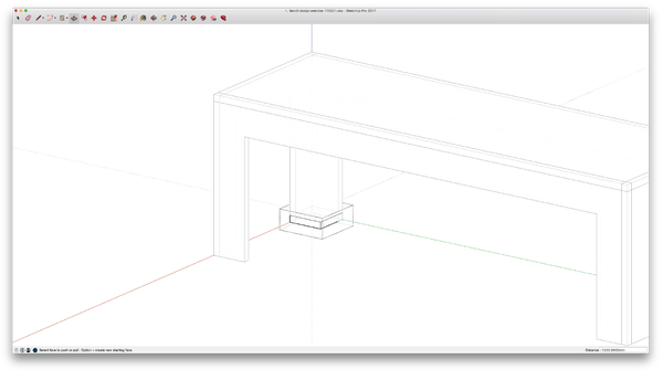
Figure 4-11. Model the first foot
Evaluate and Analyze
Now that all of the bench parts are well defined, it’s a good time to analyze your design in its rudimentary state before going into further detail. Step back to look at your model with fresh eyes. Clear your workspace a bit, so you can get a better view.
Now that you’ve created your bench parts, you no longer need to reference the massing and stock material, and you can hide them from view. With each placed on its respective layer, zzz_stock and zzz_massing, you can hide both objects (and easily show them later, if needed).
Scale
Use a scale figure to gauge the size and proportions of your design. After working intensively in any 3D CAD environment, your project can feel rather scale-less. A scale figure is an easy way to give some context.
Upon opening a new SketchUp file, you’ll find a default scale figure. Putting this figure onto its own layer (e.g., zzz_sophie) allows it to be easily turned on and off for reference. You can download one from SketchUp’s 3D Warehouse model repository.
Iteration
Design is a back-and-forth process between art and engineering. Good design manages to integrate both. As you develop a design in greater detail, it’s essential to continually incorporate this process of stepping back to analyze so that you can improve your design along the way. This cycle of continual improvement is called iteration.
Earlier, we walked you through the process of evaluating the bench massing and adjusting its proportions to 1:1:3. Examine the form of the beam and legs relative to the overall bench proportions. Does frame depth or leg width make the bench feel too light, too long, or too heavy? Does the bench seem sized appropriately to accommodate the scale figure? We won’t make adjustments as part of this exercise, but now would be a good time in the process to do so if you decide to go that route.

Figure 4-12. The iterative process
Evaluate and Refine Structure
Now, look over the model again, this time with an eye on structure. The legs, beams, and seat form a structural frame that resists the gravity loads when people are seated. As people sit down on and get up from the bench, they also put dynamic, lateral forces onto the bench structure. The seat forms a diaphragm within the frame, keeping the bench square and rigid as people take a seat. The four feet prevent the legs from splaying outward, giving the bench enough strength to support those who are seated.
In examining the overall proportions, beam depth, and leg dimensions, we see that the bench might benefit from a bit of structural reinforcement. To give our structural frame additional strength, we will add an extra beam along the center of the bench. Adding this beam allows the seat to act like a torsion box, which helps the seat to handle a long span and to keep the bench rigid.
Add a Center Beam
-
Copy the front part; then move it toward the center of the bench and align its top midpoint with the center of the seat.
-
Delete the legs; they’re unnecessary—we’ll leave only the beam that locks into the side parts. Figure 4-13 shows the bench with the center beam added.
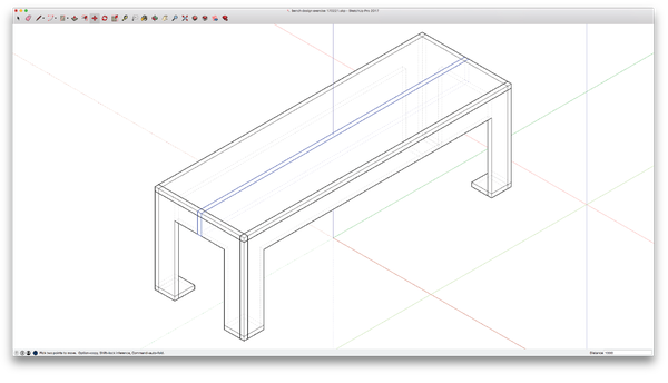
Figure 4-13. Copy and modify the front piece to form a center beam
Organize with Components
The process of determining and applying a program, developing a massing model, and roughing out the parts of your bench is called schematic design. You’ve solved a series of design problems in a specific and thoughtful way, and now you’re ready to commit to your design decisions. In the next steps, you’ll convert your bench parts into SketchUp components and configure them for designing simultaneously in two and three dimensions.
Components create extra organizational steps, but help to streamline the design process and your workflow. They allow you to edit and visualize a part simultaneously in 2D and 3D, and to manage duplicate parts and elements in a design. Give your components short, simple, easily recognizable names—imagine that you’ll ultimately want to share your file with someone, and you want to make it as easy as possible for them to pick up where you left off.
Take a minute to step back and count the unique parts in the bench. Is there an opportunity to minimize errors and adjust the design by replacing duplicate parts with components? Yes! While the bench is made of eleven pieces, it only has five unique parts. The four feet are identical, as are the two side parts and the front and back parts. These part types, combined with the seat and the beam, comprise the five unique parts shown in Figure 4-14. By turning each unique part into a component, you’ll only have to edit one part, and any changes or modification to that part will take place across all of them. Next, you’ll make unique parts into components (refer back to the steps outlined in “Components” in Chapter 3).
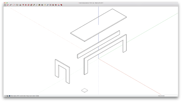
Figure 4-14. Eliminate duplicate parts
Define Components
-
Make a copy of all ten bench parts and paste them onto layer 000_Bench model.
-
Turn Layer0 off. Your bench parts and material stock should still be visible.
-
Delete all duplicate parts. Make sure that you move to layer 000_Bench model first and delete the parts on that layer.
-
Make each unique part into a component, by selecting the part and then right-clicking and clicking Make Component.
-
Name the components:
-
000_Bench Beam
-
000_Bench Front
-
000_Bench Side
-
000_Bench Foot
-
000_Bench Seat
-
-
Your five new components should appear in the component palette, matching Figure 4-15.
-
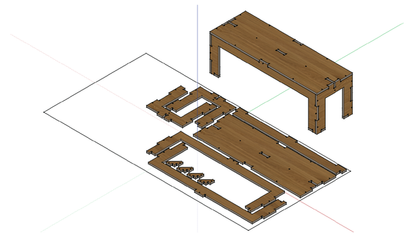
Rebuild your 3D model with the bench components. It should look like the bench in Figure 4-16.

Figure 4-15. Newly created components in the Components palette
Flatten Model, Layout Parts
In anticipation of developing toolpaths, copy your bench components and lay them out onto a virtual cut sheet. As component copies, these “flat” parts will automatically update along with the evolution of your design.
-
Turn the underlay layer (000_Bench under) back on. You’ll need to use the 2D stock material boundry to layout your parts for machining.
-
Copy the entire model and paste it onto the flatten layer, 000_Bench flat (Figure 3-4).
-
Rotate each individual part down onto the stock outline, aligning the bottom face of each part to the plane of the outline.
-
As you place parts within the cut sheet boundary, match the flattened lay out shown alongside the rebuilt model in Figure 4-16.
-
The layout in Figure 4-16 keeps outside faces of the bench facing upward, leaves adequate space between parts, and rotates long parts so that they nest into one another. For a comprehensive explanation of these and many other factors to consider when you lay out parts, refer back to “Flattening and Layout”.

Figure 4-16. Rebuild model with defined components
Design Development: Joinery
With parts defined, converted into components, and organized into both 3D model and the 2D cut sheet, you’re ready to move into the smaller scale of detail. While the phase you just completed is called schematic design, the next phase, where you will be designing joinery, is referred to as design development.
Thus far, you have modeled parts to “pass-through” one another in an impossible way. Early in the design process, it is sufficient to sketch things in this way, so you can work through the larger scale issues of your design. Now that you’ve resolved the larger issues, you can move onto the details, like composing slots, tabs, and joinery at these points of overlap.
Chapter 2 explains how joints create an interdependency between furniture parts, which improves the structural stability of the bench by distributing loads and forces evenly. To gain the advantages of joinery, it’s critical to distribute joinery in the right places and to properly position, orient, and size joints to maximize contact between parts.
Take a look at your bench and identify the distinct conditions where parts converge and where joinery should go. Start thinking about what kind of joinery assemblies might be most appropiate for each intersection (refer back to “Eight Basic CNC Joint Conditions”).
This section takes you through modeling a series of common joints for the bench. To keep things simple, we’ll stick to mostly edge-to-edge joints (also described as lazy fingers) for joining the seat to the legs, the legs to the feet, and the legs to one another. For the cross beam that interlocks with the seat and sides, you’ll model end-to-face and end-to-face-to-edge joints. In the process of forming all of the bench joinery, you’ll produce a corner assembly, tab assembly, hanger assembly, and foot assembly. Let’s get started by organizing the bench’s many slots and tabs.
Joinery Organization
Finding some kind of order helps you properly locate and distribute joints, and it facilitates component repeatability. To give some order to the bench joinery, we will orient details symmetrically, work with standard sizes, and keep all joints consistently aligned to reference lines. A clear, consistent ordering system like this will coordinate our joinery placement with the proportions of the overall bench, so joinery and parts form a harmonious composition with the object overall.
Before jumping into the steps of modeling joinery, it helps to first draw multiple reference lines on Layer0. A datum and center line assist you in precisely locating and aligning slots and tabs. We will follow a process similar to the one used to make guidelines for forming the U-shaped bench legs.
In addition to working with reference lines, it helps to find opportunities for consistency. It will simplify things, for instance, to make all tabs and slots one size that matches the 4″ (100 mm) dimension of the beam and legs. We can always make adjustments later, but 4″ (100 mm) is a good starting point that will be easy to manage while modeling the various details.
Draw Seat Reference Lines
-
Sketch two reference lines along the top of the beam. Sketch a third parallel line and center it between them. This is your centerline.
-
Make two copies of this centerline, moving the first 2″ toward the front of the seat and the other 2″ toward the back.
-
Sketch a line perpendicular to the beam, connecting front and back midpoints of the seat. This is the centerline in the short direction.
-
Make two copies of this line, moving the first 2″ toward the left end of the seat and the other 2″ toward the right end.
-
Draw a line along the top end of the seat and move each 4″ toward the center of the bench. Then repeat this step at the other end.
-
Your bench should now look like Figure 4-17.
By snapping to midpoints and endpoints of your model, you can quickly draw reference lines. Use the measuring tool to confirm the distance between guidelines and parts of the model.

Figure 4-17. Bench with reference lines overlayed onto the seat
Draw Sides Reference Lines
In these next steps, you’ll draw reference lines to organize the joinery on all sides of your bench.
-
Draw a line along the front of the seat and move it down to the midpoint of the legs. Being on the midpoint, this line will be 9″ (225 mm) from both the top of the seat and the floor.
-
Copy this reference line and move it up 2″. Make a second copy and move it down 2″.
-
Draw a vertical reference line between the top midpoint of the front and ground.
-
Copy this vertical line and move it 2″ toward the left side. Make a second copy and move it 2″ toward the right side.
-
Draw a vertical line from the top midpoint of the side. Copy this vertical line and move it 2″ toward the front. Make a second copy and move it 2″ toward the back.

Figure 4-18. Guidelines overlayed onto the front and side
Make Joinery
This next section walks you through the process of modeling the joinery, by using the reference lines you just drew. Going part by part, you’ll get started on making a corner assembly, and what will eventually become a tab assembly. You’ll start with the simple task of adding slots in the seat, and follow up by modeling both slots and tabs in the front, back, and side parts. The section will then walk you through the slightly more complex task of modeling a hanger assembly and foot assembly, which involve joining together three parts.
Create Seat Slots
The seat has five slots. You’ll first model its four perimeter slots, each at the midpoint. Then you’ll start on the tab assembly by modeling a fifth slot centered exactly in the middle of the seat.
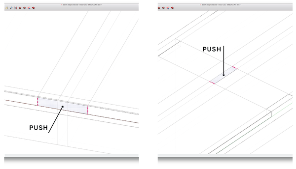
Figure 4-19. Push slots into the sides and top of seat
To form each perimeter slot, you’ll start by drawing small, precise construction lines outside the component, by snapping to the guidelines and to the model parts themselves. These construction lines help you accurately form the surfaces from which you use SketchUp’s Push/Pull tool to shape the slots.
-
Draw two vertical construction lines at one end of the seat, by using the guidelines as a reference. Each construction line should be ¾″ (19 mm) tall and spaced 4″ (100 mm) apart. See the left-hand side illustration in Figure 4-19. Select all construction lines and go to Edit→Cut.
-
Fully select the seat component three mouse clicks are required to select and edit the component, and Edit→Paste the construction lines into it.
Always draw construction lines outside of the component; then cut and paste them into the component when it’s selected for editing. Drawing construction lines directly inside the component can cause the lines to interfere with geometries. This process of drawing, cutting, editing, and pasting becomes automatic after you do it a few times.
-
Form a 4″ × ¾″ slot at the end of the seat, using the Push/Pull tool. Push the rectangle ¾″ into the seat edge. The resulting slot should be 4″ × ¾″ × ¾″.
-
Create an identical slot on the opposite end of the seat.
-
Create 4″ × ¾″ slots on front and back seat edges. Exit the component, and using guidelines, locate two vertical construction lines at the middle of the front edge. Cut and paste the construction lines into the component.
-
Push a 4″ × ¾″ × ¾″ slot into the front edge, using the Push/Pull tool. Repeat these steps to create an identical slot on the back edge of the seat.
-
Double-check length and width with the Measure tool. It’s especially important that your perimeter slot width aligns with the ¾″ thickness of the adjacent part.
Measure as you go, after making slots (and tabs). Use the measure tool to check that faces align, and that you modeled the length and width precisely.
-
Create two horizontal construction lines in the seat center. Exit the component and draw using the guidelines and the beam as your reference. These construction lines will be ¾″ tall and 4″ apart, as seen on the right in Figure 4-19. Cut and paste the construction lines back into the component.
-
Make the center slot in the seat, using the Push/Pull tool to push the 4″ × ¾″ rectangle all the way through the seat.
-
Exit the seat component.

Figure 4-20. Seat with slots in sides and top
Make Joinery on Front
In this section, you’ll form slots and tabs to create the end-to-end joints that comprise the corner assembly, connecting the front, back, and sides. In these steps, you will apply the same techniques of drawing construction lines to help accurately define surfaces that you will then push/pull into tabs and slots.

Figure 4-21. Front with three new tabs
-
Draw construction lines on the top edge and two side edges of the front component, using the guidelines as well as the slot you just modeled on the seat front as a reference. Select all construction lines and select Edit→Cut.
-
Fully select the front component three mouse clicks are required to select and edit the component. Edit→Paste the construction lines into place.
Use previously modeled slots and tabs as references to assist you in drawing construction lines and for pushing/pulling corresponding slots and tabs into alignment.
-
Using the Push/Pull tool, push either end of the top edge down so that these edges align with the bottom face of the seat. This leaves a 4″ × ¾″ × ¾″ tab at the middle that fits the front seat slot.
-
Form a tab on the side of leg by using the Push/Pull tool. Push the surfaces above and below each side tab, leaving a 4″ × ¾″ × ¾″ tab centered on the edge of the leg. Repeat on the other end of the part.
-
Exit the front component. The front part should have three tabs, as illustrated in Figure 4-21. Notice that the back part will automatically update.
Make Joinery on Sides
-
Draw construction lines on the top and both side edges of a side component. You can use the slots modeled on the seat and the front/back as reference. Select all construction lines and go to Edit→Cut.
-
Fully select a side component—three mouse clicks are required to select and edit the component. Edit→Paste all construction lines into place.
-
Form the top, center tab, using the Push/Pull tool to push either side of the edge down. Leave a 4″ × ¾″ × ¾″ tab that fits the slot in the middle of the seat edge.
-
Form a 4″ × ¾″ × ¾″ side slot into the edge of the side leg. This slot corresponds to the tab on the front leg. Repeat on the other leg. The side part should now have a tab on the top and slots on either side, as shown in Figure 4-22. Notice that the other side part automatically updates.

Figure 4-22. Side with slots on legs and tab on top
Make Hanger Assembly
Forming a hanger assembly requires the same techniques used previously, this time to modify three parts, the beam, side, and seat. While it seems like a complex intersection of parts, they are easily shaped if you go part by part and draw construction lines to form the Push/Pull surfaces. Use the guidelines, as well as previously drawn slots, to help you locate construction lines accurately.
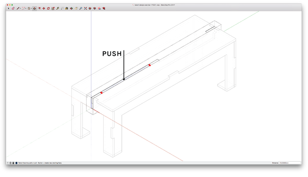
Figure 4-23. Push into top of beam, to form center and end tab
-
Draw a horizontal construction line 4′ across the top end of the beam. Draw a second construction line where the end of the seat slot intersects the beam. Select all construction lines and select Edit→Cut.
-
Select the beam component. Paste the construction lines into the component. Using the Push/Pull tool, push the surface between both lines ¾″ down, as shown in Figure 4-23.
-
Repeat on the other end of the beam. This leaves a 4″ × ¾″ × ¾″ tab at the middle that fits the center slot of the seat.
-
Draw a horizontal construction line at the midpoint on the end of the beam. Cut/Paste it into the component. Using the Push/Pull tool, push the surface below the construction line ¾″ into the beam. This leaves a tab at the top half of the beam. See far left illustration in Figure 4-24. Repeat this on the other side of the beam.
-
Exit the beam component.
-
Create a slot for the newly formed beam tab. Use the beam tab to locate a construction line. See far right illustration in Figure 4-24.
-
Select the side component. Paste the construction line into the component and push the corresponding slot through the side.
-
Exit the side component.
-
Create a slot in the seat for the top beam tab. Use the beam tab to locate a construction line in the seat. Select the construction line and go to Edit→Cut.
-
Select the seat component. Paste the construction line in place on top of the beam tab and push the corresponding slot into the seat. Repeat at the opposite end of the seat.
-
Exit the seat component. The beam, side, and seat parts should look like the parts shown in Figure 4-25.
-
Delete all guidelines (or move them onto 000_Bench under).
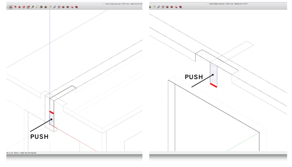
Figure 4-24. Push end of beam to form hanger; push corresponding slot on side

Figure 4-25. Exploded view of complete hanger assembly
Form Foot Assembly
Similar to the hanger, forming a foot assembly involves modifying three parts: the front, side, and foot. This exercise starts with shaping the triangular chamfer in the foot and then goes part by part to form the joinery that connects the foot to the base of the legs. As you work your way around parts, rotating the 3D view will help you to better see and select surfaces.
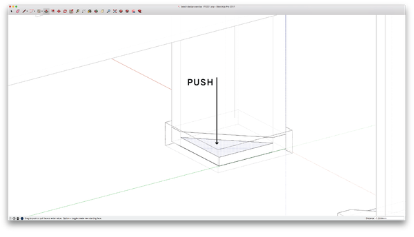
Figure 4-26. Push to remove triangle shape from square foot
-
Rotate the view, so you can see the inside of the leg assembly.
-
Draw a diagonal construction line at the intersection between the foot and each leg. Select this line and go to Edit→Cut.
-
Remove the inside triangular corner. Fully select the foot component and Edit→Paste this construction line into the component. Using the Push/Pull tool, push down to remove a triangular shape from the foot, as shown in Figure 4-26.
-
Exit the foot component.
Now that you’ve given the foot a direction, check your 3D model. You may need to rotate your other foot component copies so that they properly align with each leg.
-
Rotate the view, so the outside of the leg and foot is visible.
-
Locate the tabs on feet and legs. Draw a vertical construction line on the midpoint of each outside face of the foot.
-
Form the joinery between the foot and legs, as shown in Figure 4-27. Starting with the foot, use the Push/Pull tool to push slots into the foot.
-
Make tabs at the base of the legs, starting with the side leg and then front leg. Make matching slots on opposite legs of each part.
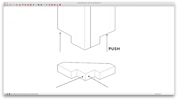
Figure 4-27. Shape end-to-end-to-end joint
Analyze Bench Joinery
After adding so many small details into the design, step back, zoom out, and examine the logic and effects of your joinery. Evaluate whether the direction, location, and proportion of all joints support the bench’s hierarchy of function, as well as its process of assembly.
For instance, part overlaps should accommodate seated individuals, who will have the most contact with the top and front of the bench. In the design, you’ll see that most of the seat covers the front edge, with small tabs pushed toward the center and ends. The seat surface is continuous where two individuals are most likely to sit. In addition, joinery adds a nice detail to the middle of the seat and suggests a subtle boundary between two seated individuals.
Another issue to analyze at this point is constructability. It’s entirely possible to design a piece of furniture in a CAD model that is physically impossible to assemble in real life. Consider the process of assembly as you design parts and locate joinery. In the case of the bench, it’s easy to envision a straightforward sequence of assembly that forms a frame with the four sides, places the beam and seat on top, and the feet on the bottom.
Evaluate Joints
In these next steps, you’ll circle back through your model and organize the parts to prepare for the next steps.
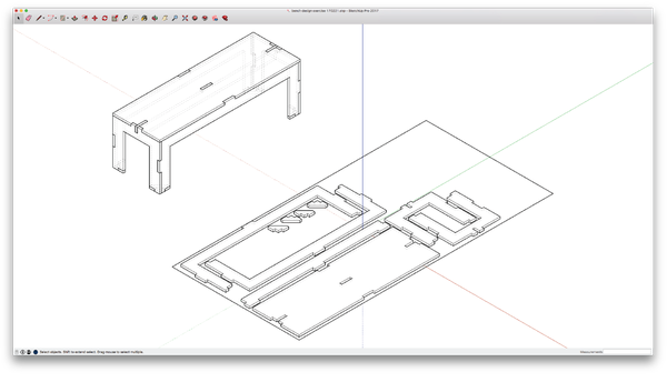
Figure 4-28. Bench with all joinery
-
Turn on 000_Bench flat to review your 2D sheet layout parts alongside the parts in their 3D configuration.
-
Look at the 2D sheet layout and confirm that there is adequate spacing between components, especially after tabs have been introduced.
-
Check that components in the 3D model haven’t shifted out of place and also look over all of your joinery to ensure that tabs align with slots and faces. If any faces or components are out of place, modify the component to bring it or its faces into alignment with adjacent parts.
Design Refinement
Now that you’ve developed a design that integrates function with structures and joinery assemblies, material and fabrication, and construction feasibility, it’s time to analyze the bench as an overall design. Good design emerges when all of these issues are successfully interrelated. However, it’s only at this point in the process when you’re fully acquainted with all of the issues that you have the ability to handle them simultaneously. This is the point in the process when good design happens. In the next section, you’ll walk through the steps to analyze and highlight opportunities to make overall adjustments to the design.
Evaluate the Overall Design
-
Examine overall bench proportions. Now that all the details have been added, do the elongated proportions complement the grain direction? Or should parts be rotated on the sheet?
-
Consider individual part proportions that allow all parts to share a common proportional language that complements the whole. Adjust beam depths or leg widths to make them consistent. Modify the overall bench dimensions if it makes sense.
-
Coordinate all joinery so that it enhances the overall object. Do all tabs share a consistent size? Do similar joinery conditions use similar joinery? Can a slot and tab be resized or relocated, or might new tabs be added or subtracted?
-
Look for overall design improvement. Consider whether you can do less with more. Determine whether every design decision relates everything to everything, with every shape working ergonomically, structurally, aesthetically, and for fabrication and assembly.
As you improve and iterate on the design, explore options on your sketch layer, Layer0. Copy components to this layer and make them unique. This way you can test ideas, while preserving your original design.
Sniglets and Fasteners
After finalizing the overall design, you’re ready to introduce the finer details like sniglets and fasteners. You have already read about fillets and sniglets in Chapter 2. This exercise walks you through the steps of how to implement them in a design. The next steps will also show you how to incorporate other details into a design, like holes that accommodate fasteners.
It’s quite useful to make sniglet and hole components that you can copy, place, and rotate as required throughout the model. Using one “master” reduces the number of mistakes and the enormous time and tediousness involved in drawing each separately. For holes, you can make a master hole that fits a particular fastener. By using components, you can later adjust its diameter if you decide to introduce another size of fastener. In these next steps, you’ll make a master sniglet and master hole to use in your project.
Draw Sniglet and Hole Components
-
Draw a master sniglet on Layer0 by following the instructions in “Exercise: How to Draw Fillets”. Assume a 5/16” (8mm) diameter that works with a typical ¼″ end mill for our ¾″ sheet material.
-
Select all segments. Then make the sniglet into a component. Name the component sniglet 8mm.
-
For the fastener hole, draw a 2D circle on Layer0 to accommodate our anticipated fastener size. We’ll use a ¼″ (6mm) diameter circle to accommodate common hardware.
-
Select the circle and make it into a component. Then name it circle 6mm.
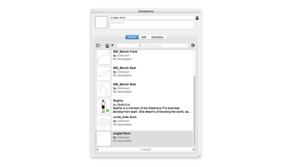
Figure 4-29. Sniglet and hole components
When naming components that you might want to import into other projects, add dimensional information to the component name. You’ll always know the size of the circle or sniglet at first glance, without having to measure the geometry.
Model Sniglets
Sniglets go into every interior corner, to eliminate corner material and to accommodate flush-fitting joinery. While some CAM programs (like VCarve Pro) have utilities you can use to add dogbone or T-bone fillets to your design, this extra step allows you a bit more control. You can pay more attention to the actual corner detail profile, while also thoroughly considering its exact direction and placement in the overall design.
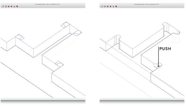
Figure 4-30. Locate sniglet profiles and then form into 3D
-
Working on a 2D flattened part, place a sniglet at every inside corner. Be sure to work outside the component itself as you place and arrange sniglets.
-
Select the collection of sniglet components and go to Edit→Cut.
-
Select and Edit the part component. Edit→Paste the sniglet collection and explode the individual sniglet components.
-
Using the Push/Pull tool, push the sniglet shape into and through the part.
-
Exit the part component and repeat until all parts have sniglets on every inside corner.
It’s usually more convenient to work on the 2D parts as you introduce sniglets and holes, especially in those cases where access to the part is limited. When you want to work on parts configured in 3D, it’s helpful to use transparency view options as much as possible, so you can clearly understand parts. It can also help to isolate or temporarily move components in 3D to work on them.

Figure 4-31. Finished sniglets on the bench seat

Figure 4-32. Bench parts with sniglets
Model Holes
To ensure a fastener securely attaches two parts together, center holes so that they are in the middle of a tab and in the middle of the material thickness, as shown in the far left in Figure 4-33. Working in the 2D parts layout, draw temporary reference lines to assist you in accurately placing all fastener holes.
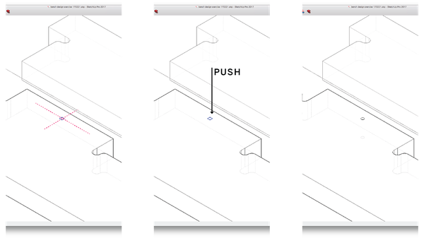
Figure 4-33. Locate and make holes
-
Working with one 2D part at a time, draw reference lines to help you center holes in the middle of each tab.
-
Select a hole component and center the hole at the intersection of the reference lines. Be sure to work outside of the part component, as you place the holes component. See the center illustration in Figure 4-33.
-
Select the collection of hole components for a single part and go to Edit→Cut.
-
Fully select and edit the part component, place holes, and explode them.
-
Using the Push/Pull tool, push the hole shape into and all the way through the part, as seen in the far right of Figure 4-33.
-
Exit the component and repeat until all the parts have holes.
-
Delete the guidelines.
Sometimes it isn’t possible to fit a fastener into tight spots, like in between tabs in the hanger and foot assemblies. Since the fasteners only need to assist the joinery in holding parts together, you can omit any fastener hole that seems to crowd the joinery.
Visualize and Simulate
3D modeling software isn’t just for building a model. By allowing you to quickly and accurately visualize your design, it can be quite generative in the design process. Being able to see the thing you are working on from different angles on the screen allows you to analyze and develop a model further. You can quickly flip the model around from front to back and bottom to top. You can evaluate proportions in flat, orthogonal views. You can verify that all fasteners and sniglets are properly placed. And you can even compare your design to a scale figure.
SketchUp, like most CAD software, allows you to toggle between different visualization modes. Sometimes it helps to see all lines at once in wireframe, or to focus on profiles in hidden line, or to examine only planes and volumes in surface render. When you reach a stopping point in modeling, running through these different visualization modes can prove quite helpful in evaluating your design.
Going further, you may find it valuable to actually add texture maps to the parts of a 3D model. This visualization helps you evaluate the grain direction and consider different materials relative to the design. Texture maps also allow you to see the contrast of edges and joints relative to the overall design.
Beyond the modeling program, rendering software can take simulation a great step beyond. You can use rendering software to thoroughly study the materiality and overall effects of your design in an environment. You can study your model relative to light, reflection, and shadow, and you can see the effects of accurate materials. The renderings throughout this book were generated using Maxwell Render, a software platform we use to document and communicate AtFAB as well as our other projects.