
Chapter 5. Precision-Fit Plywood Joinery
In many ways, plywood can be the perfect material for your CNC projects. As a natural material with an inconsistent thickness, however, it can also be challenging to work with. As enticing as it is to jump right into cutting a CNC project, digital craft results from understanding material properties and taking time to prepare. Perfectly executed plywood joinery does not happen on its own. However, by carefully measuring your plywood, adjusting your CAD files, and then testing to make sure that you’ve got everything right, your job will go smoothly and yield perfect results.
Plywood
Plywood is a nearly ideal material for CNC fabricated furniture. It’s available in big sheets and comes in a multitude of styles and species. Plywood is easy to find, and it’s relatively inexpensive compared to other materials. It can span large distances, but can be flexible if needed. It can be left plain or covered with paint, clear coatings, veneers, laminates, solid wood, and other finishes. It can be easily glued or joined with mechanical fasteners.
Plywood’s advantageous properties stem from its composite, manfactured origin. Plywood is an engineered material comprised of numerous layers, or plies, that are stacked and glued together into large sheets. Within a sheet, each ply grain is rotated 90 degrees to form an especially strong material. This process gives plywood an excellent strength-to-weight ratio. Parts cut from an especially heavy material may sag under their own weight. Similarly, parts cut from a weak material may buckle under if carrying heavy loads. Furniture parts cut from plywood, however, won’t usually have this problem.
A sheet’s faces are the large exposed top and bottom layers, while the thin edge surfaces show the cross-section of plies, appearing “striped.” CNC profile cutting exposes these striped edges, providing an opportunity for furniture designs to express them in joinery details.
Selecting Materials
Your choice of plywood type can radically transform a design. A table made from raw sheathing, for instance, looks very different from the same design cut from refined, prefinished veneer plywood.
Plywood is marketed and priced to feature the face veneer, but to ensure clean CNC joints, the core is equally important. Checks, voids, and gaps on the interior plies will yield unsightly and possibly compromised joints, so it’s best to avoid lower graded plywoods that usually have these flaws. Avoid plywood or other material that has excessive camber or warping, since sheet materials that do not lie flat on the CNC bed will result in imprecisely cut parts.

Figure 5-1. Cross section of three plywood types
- Construction Grade
-
Also referred to as softwood plywood, these sheets consist of 3–7 plies made from conifers like pine, cedar, or spruce, and are used as residential sheathing or flooring underlayers. It’s the cheapest plywood type, typically not very attractive, and often contains defects. If you’re on a budget, seek out products that have sanded finishes, without warping, knots, checks, and voids.
- Cabinet Grade
-
Also called hardwood plywood and intended for cabinetry or other visible applications, these sheets have thin hardwood veneers and 7–9 softwood or composite interior plies. They are more expensive than construction-grade plywoods, but typically have far less warping, knots, checks, and voids, making them the ideal starter material for CNC-fabricated furniture.
The term “hardwood plywood” refers to the type or species of wood used, such as maple, birch, or oak. It is also frequently used to indicate an “attractive veneer.” If a top-quality softwood veneer such as cedar or knotty pine is used, that sheet is still called hardwood plywood.
- Architectural Grade
-
The highest end plywoods are comprised of 9–15 very thin, typically Baltic birch, veneer plies. Often called multiplex, such products are undoubtedly the ideal material for fine CNC furniture, and at double the cost of cabinet grade, they are also the most expensive. The thin plies, however, offer durable, refined edges. There are numerous options for unfinished and prefinished hardwood face veneers and laminates.
Nominal Thickness
Here’s where the real complication comes in: plywood is almost never as thick as labeled and described. Lumber dimensions have nominal thickness, which differs from actual thickness. Like 2×4s that are never really 2″x4″ (they’re closer to 1.5in x 3.5in), three-quarter-inch plywood is rarely actually ¾″ thick. Sheet goods are almost always thinner than specified, but not consistently so. A sheet of ¾″ Douglas fir plywood is almost never the same thickness as a sheet of ¾″ Baltic birch. And a sheet of ¾″ Baltic birch from one mill may not be the same thickness as a sheet from a different mill.
In addition, wood in general is a “living” material and can change dimensions based on temperature, humidity, and manufacturing techniques. Plywood from a particular mill may vary between batches, and even the sheets within a bundle of plywood can vary from the top to the bottom and from day to day because of environmental changes. It can even vary within an individual sheet—a sheet in the middle of a stack will generally gain and lose moisture in the edges but not on the faces.
For projects where pieces need to fit together accurately for aesthetics and/or strength, not knowing the precise thickness of your material poses a challenge. However, if you select your materials by choosing clear, flat sheets and measuring to find ones that have some dimensional consistency, you can manage the rest of the process. In later steps, you can treat material thickness as a fundamental variable that you need to plug into a very basic “measuring and scaling” equation.
Metric Versus Imperial
Like socket and wrench sets, plywood is manfactured in both Metric and Imperial sizes—and just like those tool sets, the approximations can be “close,” but are not necessarily equivalent.
We’ve put together a list of tested and recommended materials and additional sourcing information in Appendix B.
Calipers
Calipers, shown in Figure 5-2, are an essential tool for accurately gauging material thickness. Calipers measure the distance between two surfaces: either between the outside surfaces of a material (large bottom jaws) or the inside surfaces of an opening (small top jaws). While tape measures and rulers are helpful with larger dimensions, calipers offer more precise measurements, particularly with smaller items. These days, most calipers found in a shop are digital, and they are capable of measuring to at least a thousandth of an inch.

Figure 5-2. Measuring material with digital calipers
- Measure Before You Buy
-
Always bring calipers (Figure 5-2) when you shop for materials; you’ll need to measure the thickness of different plywood grades and sheets before you buy.
Plywood sheet thickness can vary from batch to batch, sheet to sheet—and even within each sheet itself. To ensure that the materials you’re buying have an aproximate matching thickness, take some base measurments and use them to help make your selections.
Most of the projects in this book use more than one sheet; the Cellular Screen in Chapter 16 uses seven. When you’re working on multiple-sheet projects, try to find some consistency across all sheets.
Even if you’re only buying a single sheet at a lumber yard or big box store, get your money’s worth and avoid project pain. Large sheets of plywood that you can barely maneuver yourself may seem like difficult items to inspect for warping, voids, and face quality—but you’ll regret it if you don’t. Remember that they want to sell you wood. It’s not exactly cheap, and you should be picky. Just start going through a pallet; employees always show up to help.
Once you have a sheet off the rack or out of the pile, turn it on its long edge and look down the length to ensure that it’s not too badly warped. Warped material is harder to hold down, doesn’t machine well, and can lead to broken tooling.
How to Digitally Dial In Joinery Fit
The key part of digital craftsmanship is matching your digital CAD file to your physical material. Now that we’ve explained the inherent dimensional variation of actual sheet materials, let’s shift our focus to the virtual side of the process.
Designed for 19mm Plywood
Designers model a project using a virtual material thickness that is approximate to real sheet material stock. Since it is a general approximation, material dimensions in a digital CAD file will likely differ from real materials, because of the variability we explain earlier. Nominal thickness in design files, or TNOM, is an assumption, not an exact measurement. To model the two-seater bench in Chapter 4, you had to assume a sheet material thickness of 19mm. Each AtFAB project in this book was modeled with sheet material in these assumed thicknesses. The interconnected joinery in the cut files derived from those 3D models will only fit together if machined from plywood with an identical thickness.
Dialing in your joinery fit requires a few methodical steps, so the nominal material in a CAD file matches the actual material you have on hand.
Because of plywood’s uncertain actual thickness, it’s critical to thoroughly measure your material. Once you know your material’s physical properties, you can then calculate the difference between the actual and virtual material thickness, and adjust the CAD file to match the actual material.
You might recall in Chapter 2, AtFAB designs use sniglets that are 110% of the actual end-mill diameter size to accommodate downward file scaling. This additional percentage ensures your sniglets won’t be too small for the end-mill, if you reduce the file’s scale to match material that’s thinner than TNOM.
The following pages walk you through the steps of measuring, calculating, and scaling.
Measure Your Materials
-
Using calipers, measure the thickness of your plywood sheet in at least four places—near the edges of the sheet—as indicated by TA, TB, TC, TD in Figure 5-3.
-
Record your measurements as you take them. Use a record-keeping strategy that you’ll be able to easily reference in the future, like a notebook or spreadsheet. You’ll find that you want to refer back to these as you work through the projects in this book.
-
Repeat. If a design uses multiple sheets, repeat this process with each individual piece of plywood.
-
Find the greatest thickness from all of your measurements on all sheets. This measurement is TMAX.
With your material’s physical measurements in hand, you’re ready to adjust your CAD file’s nominal dimension to your plywood’s actual dimension.
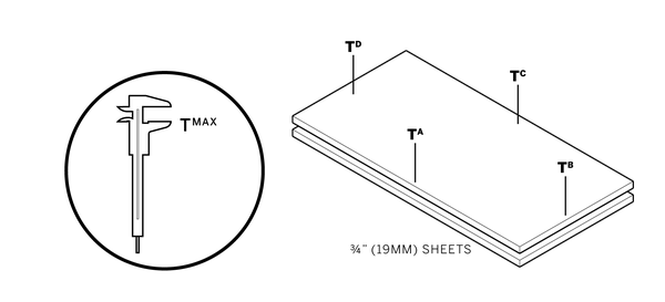
Figure 5-3. Measure material thickness at multiple points, maximum thickness is TMAX
Scale Your CAD File
The natural fluctuation of sheet material thicknesses makes standardization—and standard cut files—impossible. Because your actual material thickness (or TMAX) will never precisely match the designs file’s nominal thickness (or TNOM), you’ll need to scale your CAD file to match your material thickness or your joints won’t fit together. Cutting parts from an unadjusted CAD file will produce parts that won’t fit. Joinery will either be too loose, leaving parts to rattle around, or too tight, with tabs too fat to fit through slots.
Luckily, scaling your CAD file is a simple process.
-
TMAX / TNOM = S. Divide your measured material thickness (or TMAX ) by the nominal material thickness of TNOM to get S—a scaling percentage.
-
In the SketchUp file, turn on only the toolpathing layers.
-
Select all 2D toolpaths on the toolpathing layers and then scale them by S, the scaling percentage.
-
Save and rename the file. Add the amount scaled to the filename (e.g., AtFAB_CiBii-.9867.skp). This differentiates it from the original, unscaled version of the file, and indicates the file’s scale. You’ll forget!
Small-scale adjustments usually won’t have an impact on fastener holes. If you want to maintain a specific hole diameter for particular fasteners or pegs, scale holes with the rest of your vectors and then change the dimension of the 2D hole component.
Check that S does not reduce the cut file scale by too much. Sniglet diameter should always be equal or greater to your end-mill dimension.
Since different designers may use different standards, it’s good to make a habit of measuring slots and material thickness in any CAD file that you download. AtFAB files on OpenDesk, and other files floating around the interwebs, may use an 18mm TNOM.

Figure 5-4. Scale cut file by S, matching joinery to TMAX
Scaling, Offsetting, and Parameters
Scaling the CAD file by a small percentage, S, makes up for any discrepancies between TMAX and the nominal ¾″. This scaling method is the simplest and most direct way to match the virtual CAD design with the material, which came after much trial and error. It is worth explaining scaling in the context of other methods of adjusting a CAD file for material.
Why Scaling Works
Scaling all parts by a multiplier, S, has proven to be the most efficient and accurate way to adjust a cut file to match TMAX. As shown in Figure 5-5, scaling resizes every part proportionately, resulting in flush connections between slots and tabs. The only shortcoming of this technique is that it works best with a nominal amount of scaling.
A scale differential less than 5%, which is within the nominal thickness variation of most standard material stock, won’t be perceptible in a free-standing object.
A 5%–10% scale adjustment to furniture might be perceptible, but typically won’t affect function.
A scale adjustment greater than 10% will affect the function of a furniture piece, yielding a tabletop that is 10% lower, a chair that is 10% smaller, or having 10% less height between shelves.
Why Offsets Don’t Work
At first glance, it may seem that offsetting vectors is the simplest and most obvious way to adjust a cut file to fit TMAX. However, take a look at Figure 5-6, and examine what happens with the example slot and tab as vectors are offset.
Using this function in any CAD or CAM program inconsistently affects the X and Y disproportionately, impacting the ratio of height and width.
Offsetting creates tabs deeper than the material thickness, and it changes sniglet radii to form uneven and possibly uncuttable toolpaths. Parts and joinery don’t fit when you offset toolpaths.
The Parametric Solution
A third alternative is to adjust the file by precisely redrawing all 2D vectors to match TMAX, while still preserving the proportions of each part, shown in Figure 5-7.
However, by laboriously redrawing each part, there is a high probability of missing a small detail in the process. A powerful CAD program with parametric capabilities can automate this adjustment, while sparing you the tedium and possibility for mistakes.
Parametric software, explained in Chapter 12, can have a steep learning curve but has tremendous potential when coupled with digital fabrication. Chapter 13 and Chapter 14 are accompanied by parametric applets, which allow you to transform every furniture part, so it precisely fits TMAX.
Figure 5-5. Scaling a cut file to TMAX

Figure 5-6. Offsetting to TMAX

Figure 5-7. Parametric transformation to TMAX

Prototyping
Prototypes are used to evaluate a design at varying stages during the design and fabrication process.
From a practical standpoint, prototyping allows you to identify errors and troubleshoot defects before committing to making a full-scale, final piece. From a design standpoint, prototypes enable you to take risks with innovative ideas and to gather immediate feedback. Working digitally enables rapid prototyping, where you can iteratively cycle through a process of designing, prototyping, and making improvements, over and over.
Prototypes can take many forms, but for CNC furniture there are two kinds that are especially useful. Partial prototypes made at full scale are essential to digital craftsmanship, by helping you to dial in machine settings and to evaluate finishing techniques. Scale prototypes, made by fabricating your digital file at a smaller scale, are great for evaluating a new or modified design.

Figure 5-8. Partial prototype test pieces for each project
Partial Prototypes
Partial prototypes are small samplers of a larger design that you make using your actual project material. A partial prototype is great for trying out especially complex and tricky portions within the design, before committing to the fabrication of an entire design. Partial prototypes are also quite useful for evaluating joinery fit and ensuring that you scaled the CAD file to perfectly match TMAX.
Test Pieces
Each project in this book is accompanied by a partial prototype called a test piece, shown in Figure 5-8 and in the image that opens this chapter. They were designed to simulate the most complex joint combinations within each project. After measuring materials and scaling a CAD file, fabricating this test piece is the next step for ensuring tight-fitting joinery.
Preliminary fabrication tests prevent the disappointment and waste that comes from cutting an entire piece of furniture with incorrect settings. Each project’s test piece was designed to use as little material as possible, but still be large and detailed enough to allow a thorough analysis of all the joint conditions within the furniture piece.

Figure 5-9. Joinery fit: too tight versus too loose
To ensure that your test piece properly simulates the critical joinery of your project, it’s essential to fabricate it exactly as you would the actual furniture piece. First, you apply identical scaling adjustments (S) to the 2D test piece vectors in CAD (as explained in “Scale Your CAD File”). From there, you’ll assign identical toolpath settings in CAM software (which will be explained in “Partial Prototyping: Using a Test Piece”), and proceed to cut the test piece from the exact material that you’ll be using for the actual piece.
Most of the time, these careful steps lead to a test piece with perfectly fitting joinery, enabling you to confidently proceed with cutting your project. When joints aren’t perfect, however, the test piece is small enough to quickly make digital adjustments, cut another test piece, and compare the new fit to the previous one (“Troubleshooting” goes into greater detail with these steps). The beauty of prototypes is that they enable the iteration that’s necessary for flush joinery, the hallmark of digital craftsmanship.
Scale Prototypes
Scale prototypes are small-scale versions of a design, cut with a desktop CNC or laser cutter out of inexpensive materials like cardboard, plexiglass, or aircraft plywood. They differ from partial prototypes in that they can be used earlier in the design process. If you have access to a laser cutter at your workshop or fabrication space, you have a quick and inexpensive way to make scale prototypes of digital designs.
Although they are small, scale prototypes can assist you in analyzing structural integrity, testing accurate fit between parts, and evaluating complex patterns or embellishments. They’re also helpful if you’re making modifications to the projects throughout this book, as they help confirm that you haven’t misplaced a sniglet or misaligned a joint. Scale prototypes allow you to see the overall composition of details in physical space. Understanding the whole object enables you to intelligently analyze a design in ways that you may have not imagined, when looking at the CAD screen.
To prepare a scale prototype file, you simply follow the same steps as you would in adjusting a CAD file (explained in “Scale Your CAD File”). The only difference is that thin prototyping materials like acrylic or cardboard have a TMAX, which is much smaller than nominal plywood thickness. Scaling toolpaths to match this thickness requires a much smaller S percentage.

Figure 5-10. Scale furniture prototypes made of 1⁄8″ aluminum cut by a CNC waterjet
