
Chapter 8. Rotational Stools
Now that you’ve learned what goes into setting up a CAM file, you’re ready to cut a pair of Rotational Stools. The following pages take you through the basics of digital technique, where the precision of the digital file meets the physical variability of material, fabrication, and assembly. This first project shows you how to create tight-fitting joinery by putting the basic concepts of measuring material and scaling files into practice. It also walks you through how to evaluate fit, and it offers simple techniques for assembly, drilling, and fastening.
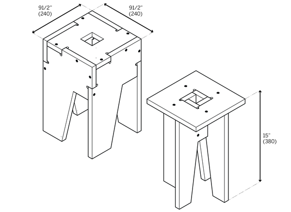
About the Design
With a substantial amount of joinery packed into a few small, simple parts, the Rotational Stools are an ideal first project. Both stools share the same overall outer dimensions, and both are comprised of five pieces, with two part types. Each stool has four identical leg parts, which are organized into a rotational structure that interlocks into the seat (see “Structures”). What differentiates the stools is how each utilizes different types of joinery. Lazy fingers are used to join the “Lazy” stool (left), while the “Lively” (right) has tight, through connections. While originally designed as small stools, many find that the pair work equally well as mini side tables.
Before You Begin
To cut a pair of Rotational Stools, you only need a partial sheet of 4’ × 8’ × ¾″ material. However, you may prefer to purchase an entire sheet, so you can use the surplus to prototype, troubleshoot, or experiment by cutting the project several times.
Since they are already quite small, the Rotational Stool file isn’t accompanied by a test piece (explained in “Test Pieces”), but we will employ that technique in other projects in this book. For this project, it’s possible to cut several versions from a single sheet of plywood, so you can test various CAD scaling and CAM setting combinations, and learn the variables that factor into achieving a perfect joinery fit.
Measure and Scale
If you went through “Job Setup” without measuring your material and scaling your cut file, proceed with these steps to prepare a CAD file and CAM settings.

Figure 8-1. How to measure and scale the Rotational Stools
Refer to “Selecting Materials” for guidelines on plywoods and follow the instructions in “Measure Your Materials” to measure your sheet material and identify its actual thickness, TMAX. Divide TMAX by TNOM to find your scaling percentage (S).
Download and open ATFAB_STL.skp. Refer to “Scale Your CAD File” and scale all Rotational Stool part toolpaths by S so that they match TMAX. Import this scaled CAD file into VCarve and follow “Job Setup” to define toolpaths for your scaled file. Once you have saved your scaled toolpath operations for output, you are ready to fabricate.
Cut and Evaluate Fit
Proceed with cutting your first set of parts on the CNC. After cutting is complete, gather all cut parts from the sheet, dust each part off, and stack similar parts together on a work surface.
Evaluate the Lazy Stool
Piece together several parts of the Lazy Stool, handling each part carefully. Hold parts so that they are squarely aligned and feel the face of a tab relative to the face of the adjacent part. Is the tab flushly aligned with the face? Or does the tab extend beyond the face (or vice versa)?
While perfect flushness between these two surfaces is your objective, the Lazy Stool will still be functional even with parts that are less than flush. The Lazy Stool has edge-to-edge and edge-to-edge-to-edge joints, which are more forgiving than the interlocking through and end-to-face connections of the Lively Stool. You won’t really know how well your parts fit until you test complex, multi-sided joinery, like the connections found in the Lively Stool.
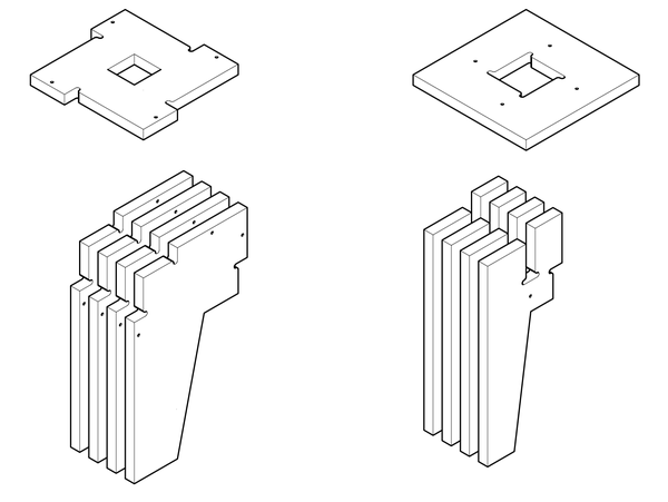
Figure 8-2. Cut parts for the Lazy (left) and Lively (right) Rotational Stools
Evaluate the Lively Stool
Just as before, piece all parts of the Lively Stool together. Do the four legs interlock with a modest amount of resistance? Does the opening in the seat fit snugly over all four leg tabs? If all five parts fit squarely and stay together on their own, it means your CAM and machine settings were correct, and your CAD file was scaled properly to fit your material thickness (TMAX). Whenever you achieve a perfect fit, record your material measurements, CAD scaling, as well as your CAM settings for future reference.
- Fit is too loose
-
If the Lively Stool parts rattle around, and the tabs of your Lazy Stool extend beyond the adjacent face, you scaled your CAD file by a percentage (S) that was too large to fit TMAX (see “Scale Your CAD File”).
- Fit is too tight
-
If it takes brute force to fit the Lively Stool parts together, or they don’t fit together at all, you scaled your CAD file by a percentage (S) that was too small to fit TMAX. Turn to “Troubleshooting” for tips on how to analyze further, so you can ultimately get a perfect joinery fit.
Troubleshooting
Don’t get discouraged when your first round of Rotational Stool or test piece parts don’t fit. When starting out, easily assembled, perfectly aligned joinery doesn’t always happen after the first or second attempt. Getting to the perfect fit simply requires additional scaling, or minor adjustments to machine settings, and re-cutting of your adjusted test pieces. This process may feel quite tedious at first. However, taking these extra steps at this stage will ultimately give your furniture square joinery, solidity, refinement, and a long, useful life. And, the more you go through the process of troubleshooting, the more knowledge you’ll gain about digital craft, and the better you will be able to anticipate. When troubleshooting, start by identifying the problem and then planning a course correction.
Measure
When you don’t get the right fit immediately, it first helps to understand the magnitude and nature of the discrepancy. Take precise measurements so that you can analyze the first outcome, and course correct. Using calipers, measure slots, tabs, and material thicknesses of several parts. Measure the overhang or underhang of a tab and adjacent face. Using a pen and painter’s tape, mark up the stool parts with your measurements and any additional notes based on your analysis.
Analyze
Compare the material thickness measurement of your parts with the original TMAX to ensure that there wasn’t an error in your original material measurements. Once you’ve determined that the original TMAX matches your current material measurement, look for consistencies in your discrepancies. For instance, slots that are larger than TMAX are usually accompanied by tabs that extend beyond the face of an adjacent part. Both of these issues can arise as the result of a CAD file that was scaled by too large of a percentage (S).
Evaluate the edge quality of your parts. Parts that easily release from the sheet and require little sanding indicate that your tool and machine settings were appropriate. If part edges are rough, your machine settings may be a factor. Chapter 6 offers more detail on the variables that factor into ensuring quality CNC machining.
Adjust
The extent and magnitude of your discrepancies determine where to make adjustments. CAD modifications are always a first remedy. Calculate the difference between slots and material thickness, and recalculate the scale percentage of discrepancy.
Open the CAD file and scale the entire file by this amount (see “Scale Your CAD File”). Proceed with programming toolpaths and cutting the adjusted parts exactly as you did the first time. (When troubleshooting, it helps to isolate the cause/solution and avoid multiple adjustments.) Put the newly cut parts together and evaluate the fit. Repeat this scaling and recutting process until you arrive at the ideal fit.
Modifying CAM settings is ideal when all of your parts fit, but they are only slightly greater or less than flush. When you are a hair off from a perfect fit, test combinations of machine feed, speed, and other settings in your CAM software (see Chapter 6). If these CAM setting modifications don’t correct the fit, or if part discrepancies are more significant, then further adjustments to the CAD file are required.
Evaluate and Iterate
After making appropriate CAD and CAM adjustments, go back and rescale the original CAD file, reassign toolpaths in CAM, and recut the parts. Compare the fit of your new parts with the fit of the first round and make new notes on the new parts. Continue this process until you have achieved a flush fit. It always helps to compare and analyze each adjustment, in order to understand the relationship between scaling, machine settings, and materials.
Carefully record all adjustments to your machine settings and CAD file. Starting from the first modification you make to the original file, keep a chart of changes to the files and write settings directly on a test piece after it has been cut. Having a clear record becomes especially helpful when making multiple adjustments and evaluating several Rotational Stool versions or test pieces alongside one another.
Assemble
After you have successfully cut a pair of Rotational Stools with parts that fit perfectly, you are ready to assemble them. Collect your parts, and very lightly file or sand any rough edges. Keep the sanding block and file parallel to the edge and don’t oversand or round the edges. Carefully dust off each part and stack similar parts together on a protected work surface. It helps to use a cloth or moving blanket, so as not to scratch the parts or damage the worktop.
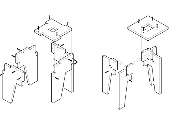
Figure 8-3. Assembly diagram of the Rotational Stools
Prior to assembly, gather your hardware and matching drill bit, drill, and blue tape, as well as an Allen wrench or screwdriver that matches your fasteners. Place everything within easy reach. Lay your recently cut stool parts out in the order of assembly, with the right sides facing upward.
The Lively Stool is best assembled upside down. First, place the seat with the top facedown on your work surface. Interlock the four legs and snap the four leg tabs into the center hole of the seat. You might find blue tape and an extra set of hands especially helpful in keeping the Lazy Stool parts together during assembly. Start by placing the seat with its top facedown on the work surface. Piece all four legs together and secure them firmly with blue tape.
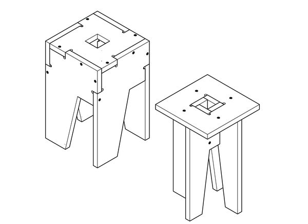
Figure 8-4. Lazy and Lively Rotational Stools
Fasteners
Since the furniture joinery does most of the structural work, the lighter load on your fasteners means you have some flexibility in your choice of hardware. Fasteners ranging from wooden pegs to heavy-duty industrial fasteners to the lightest of screws will do the job and can be as minimal or as expressed as you want.
Wooden pegs, either prefabricated or cut to size from dowels, create a subtle inlay detail against plywood parts. Since pegs are glued into place, they are best used for furniture that won’t be dismantled. Peg and hole diameters should match so that the peg fits through the hole, requiring a bit of pressure. Length should be about twice your material thickness (2 * TMAX). Dowels are best inserted with a very small amount of adhesive in order to fix the furniture parts and the dowels themselves in place.
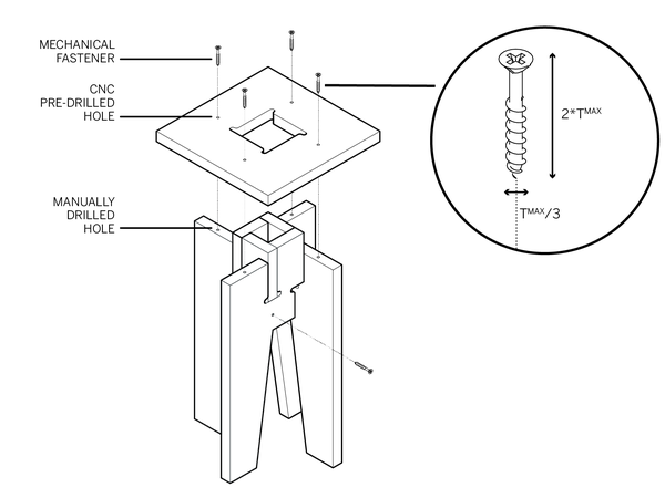
Figure 8-5. Length (2 * TMAX) and diameter (1/3 < TMAX) fasteners pass through pilot hole and into opposing part
If you intend to dismantle a piece of furniture, or you just like the ease and appearance of hardware, it’s best to use screws that are easily removed and reused. Polished finishes are often better at reflecting the furniture material, so they end up blending in to the surrounding material. Like dowels, fasteners should be about twice your material thickness (2 * TMAX). Any less and the fasteners aren’t bearing deeply enough into the material, and any longer demands more drilling and screwing than is really necessary.
Fasteners should match the hole made by your CNC router so that the shank passes through the hole with threads just grazing the interior. The screw head diameter should always be greater than the hole diameter. Select a thread diameter no greater than one-third of your overall material thickness (1/3 < TMAX), which should ideally match the hole made by your CNC router. We often work with Stafast decorative screws, particularly the small, flush-mounted SCS0540HD. With a length of about 1 ½″ and shank diameter that fits within the 1⁄8″ fastener hole, the screw is perfectly sized for ¾″ plywood parts.
How to Drill
While the CNC router predrills holes into the face material, you’ll still need to manually drill holes into the edge of the opposing part for pegs and hardware. Predrilling holes for pegs is a necessity. Though predrilling prior to screwing in fasteners may seem optional, it’s actually a good practice for many reasons. It prevents splitting of the plywood plies, and also allows a clean contact between the fastener threads and the hole. Also, you’ll have a greater choice of fasteners, if you’re not relying on self-tapping screws.
Use the hole cut by the CNC as a pilot hole, helping you perfectly locate the fastener and align your drill.
-
Piece furniture parts together and secure with blue painter’s tape (Figure 8-6).
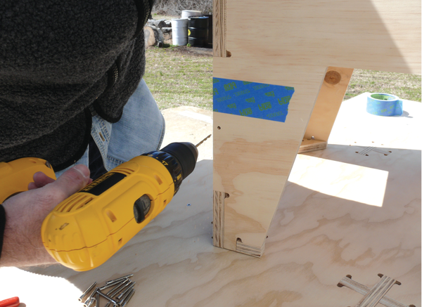
Figure 8-6. Drill through pilot hole
-
Predrill all holes for fasteners (Figure 8-7). Start by working around the sides, before drilling seats and tops. For furniture pieces with feet, save the feet for last. Drill directly through the pilot hole cut by the CNC machine, keeping your bit perpendicular to the face. Drill into the edge of the opposing part, matching the drilling depth to the length of your fastener.
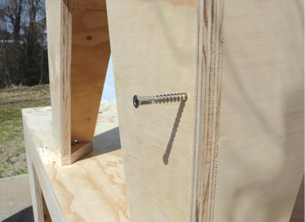
Figure 8-7. Insert fastener
-
Screw in fasteners, matching the drilling sequence. Start by securing the sides to each other first, then attach seats (or tops), and then feet (Figure 8-8).

Figure 8-8. Tighten fastener by hand
Consider the starting point and sequence of drilling and fastening. It helps keep joinery aligned when you drill and fasten from the center of the furniture and work outward to the edges, corners, and feet. Working methodically will also help prevent missing a hole!