
Chapter 6. Machining For Designers
This chapter dives deeper into computer-controlled routing fundamentals, with a basic overview that covers large-format CNC router and end mill anatomy, essential workshop accessories, and machining basics like feeds and speeds—with a focus on plywood projects.
Machining Begins with Material and Tooling
When planning a CNC project, your first question should always be: “What material do I want to cut?” All machining begins with your choice of material—every subsequent choice stems directly from the material you select.
The follow-up question is: “What cutting tool should I use?” Every material has specific tool geometries that work well, and each cutter and material pairing has an optimal range of rotational speeds.
Computer-controlled cutting machines that use rotational tooling have emerged from two very different material-focused disciplines: woodworking and metal machining, also known as milling. As you grow as a maker—or begin to design for other materials—you’ll encounter online, print, and in-person advice from experienced woodworkers, life-long metal machinists, and versatile fabricators who work in many materials.
Each field has its own best practices and terminology, so to help you understand the fundamentals, we’ll start at the beginning—with a brief history of tool rotation.
Spindles and Speed
Generically, a spindle is a rotating shaft that transfers motor power to a cutter as it spins around an axis. When applied to a material, the tool attached to the spinning spindle bites into the substance, creating subtractive waste products, called chips, with each revolution.
The frequency of rotation, or speed, of a turning mechanical component around a fixed axis is measured in revolutions per minute. Rotational speed can be abreviated as: RPM, rev/min, or r/min.
On a machine, the term “spindle” refers to the entire motorized assembly that moves up and down the z-axis, not just the shaft. Spindles conventionally spin clockwise (although there are a few that spin counter-clockwise), and most tooling—and all the machining information in this book—assumes a clockwise rotation.
Chip Formation
As the spindle turns a tool, the cutting edge slices into the material, removing a fragment called a chip. The size of the chip is called chip load.
Chips are not just the waste product of machining—they are key to heat dissipation. The act of cutting a chip generates a small amount of frictional heat. Chips absorb this heat, pulling it away from the tool and the workpiece, as they are ejected through the flutes. If this heat were allowed to build up, it could quickly dull tools, leave burn marks on wood, or even start a fire.
Creating chips that dissipate heat quickly while balancing both cut quality and time spent is fundamental to machining. The speed that a machine turns a cutter has an impact on what materials can be cut and what type of tool can be used. Different machine types have different ranges of spindle speed.

Figure 6-1. Chip formation
What Is a Milling Machine?
Mills were invented in the early 1800s. Originally they were large, heavy, rigid, high-precision, motorized (but not computer-controlled) machine tools made to cut very hard materials like metal. The spindle that rotates a rotational cutter capable of lateral cutting called an end mill is stationary, while the material is clamped in a vice to an x-y moving table.1 Most mill spindles have a speed range of 3,000–7,000 RPM. Anything higher than 7,000 RPM is considered, routing or high-speed machining (see “High-Speed Spindles”).
What Is a Router?
In 1915, Oscar Onsrud and his son Rudy repurposed a jet motor, creating a hand-held spindle that turned much faster than a mill spindle and ran on compressed air—founding Onsrud Machine Works. In order to cut at higher RPM, Onsrud created a new type of cutting tool that could spin at 30,000 RPM, far faster than any end mill at the time could cut. Called router bits, or router cutters, these tools had modified end-mill geometry that could cut wood at high rotational speeds and lateral feeds.
Modern routers are woodworking power tools that use router bits to carve joinery grooves, decorative moldings, engraving, inlays, or simply to cut out parts. This is usually accomplished by tracing a template, sometimes with a bearing-guided router bit. Routers come in many types and sizes and are usually handheld, but can also be mounted in a table—or attached to a machine frame. Some routers are single speed, but most have adjustable, designated, spindle speeds somewhere between 10,000–25,000 RPM, much faster than mill spindles.
For example, a Porter-Cable 7518 3-1/4 HP variable speed router used on some ShopBots can be adjusted to run at any one of five different speeds: 10,000, 13,000, 16,000, 19,000, or 21,000 RPM.
When working with a CNC router, never use a router bit with a guide bearing.
Routers can cut much more than wood; plastics and soft metals like aluminum cut well at high RPM.
High-Speed Spindles
Some CNC routers have actual router power tools attached, while others have variable high-speed spindles, so-called to differentiate them from traditional mill spindles, which operate at a much lower RPM.
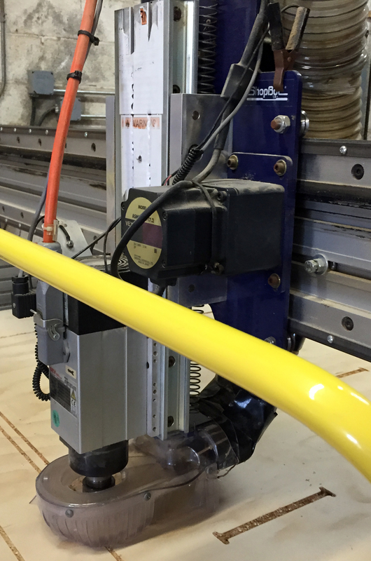
Overall, high-speed spindles (Figure 6-2) are powerful and much quieter than routers. On large-format CNC routers, like the ShopBot PRSstandard and PRSalpha,2 high-speed spindles are industrial-quality components with precision bearings that enable them to cut better and last longer than a router. They also have less runout, or rotational wobble, can operate at full torque (twisting force) at lower RPM without bogging down, and have minutely adjustable speeds from around 5,000–25,000 RPM.
There are also modern milling machines that are capable of high-speed machining, or HSM. These mills move quickly at high RPM, making light passes to achieve high metal removal rates.
Figure 6-2. High-speed spindle on a ShopBot PRSalpha CNC router
Machining Variables
Each material has a range of workable spindle speeds. For example, spindle speed for routing plywood is somewhere between 11,000–18,000 RPM. But speed is only one of several variables in the feeds and speeds equation that determines how the tool, material, spindle speed, and tool movement through the material, or feed, work together to make a cut.
Knowing the optimal spindle speed range for plywood is helpful, but how do you determine the exact spindle speed to use?
Relating Everything to Everything
Feeds, speeds, and chip load are machining’s trinity. They can be defined separately, but when cutting, all three work together simultaneously to produce chips.
When trying to grasp a concept, always look at how it is measured or calculated. That’s the key to understanding exactly what the thing is, what variables are in play, and what relationships are important.
- Speed
-
Spindle speed, measured in revolutions per minute (RPM) is calculated from a combination of specific aspects of cutter geometry, feed rate, and chip load:

- Feed Rate
-
Feed rate is the velocity at which the tool moves laterally through material. Feed rate is measured in distance per time, or inches per minute, and abbreviated IPM3:

- Chip Load
-
Chip load is the amount of material removed by each flute’s tooth as it makes one revolution while being pushed along at a feed rate and spindle speed. Chip load is measured in feed per tooth, or inches per revolution, abbreviated as IPR:

Where to Begin?
The interconnected nature of feeds, speeds, and chip load are obvious from these equations. At first glance, this seems like a “chicken and egg” problem. If all the variables are dependent on one another, where do you begin?
Start with what you know: namely, that you want to cut plywood on a CNC router and that you’ll need a router bit designed for that purpose.
But before you can select a tool, you’ll need to address the following questions:
CNC Router Anatomy
Large-format CNC routers are built for quickly cutting softer materials by moving the cutting tool through a full 4′ × 8′ sheet material, which is fixed to a stationary bed. While the details of such machines vary from manufacturer to manufacturer, most share a common anatomy.
- Rails
-
The rails are extruded aluminum tracks that employ either a motorized rack and pinion system or a v-rail/v-wheel linear bearing system to create linear motion. The machine’s gantry, YZ car, and spindle sit atop and slide along the rails.
- Gantry
-
The gantry is the y-axis of the machine; it sits atop the long x-axis rails that run the length of the machine bed. It holds the z-axis carriage (and spindle) moving forward and backward along the x-axis rails.
Machines that move the spindle around while the material remains fixed are also called gantry-style machines.
Desktop machines are likely to use rods and leadscrews, or rods and belts, instead of rails. They often secure the material to a moving y-axis table while the spindle moves in the x-axis.
- YZ Car
-
It moves left and right on the y-axis across the gantry, while carrying the z-axis and the attached spindle.
- Deck and Spoilboard
-
This is the flat, rigid surface where material is placed for cutting, typically made of metal. Deck size determines the maximum material size that can be used on the machine. The deck is covered with a protective, sacrificial layer, also called a spoilboard or waste board. When the spindle cuts through material, the tool scrapes the top of the spoilboard, marring the surface. The spoilboard is replaced when it becomes worn out. The entire area (that is, the deck/spoilboard combination) is also referred to as the bed.
A bed doesn’t need to be flat like a pool table; it just has to be parallel to the motion of the tool (trammed). To ensure proper spoilboard/spindle alignment, the sacrificial layer is placed on the machine and surfaced by cutting away a small portion of the entire top face with a large bit. This preparation results in making the spoilboard surface parallel to the motion of the tool.
Spoilboards need to be maintained and should be resurfaced regularly. Deep grooves in the waste board contribute to workpiece vibration because they prevent the sheet from lying completely flat on the bed. This vibration is a key culprit in tool breakage.
- Dust extraction
-
The bigger the CNC, the more likely that it will have a built-in vacuum system attached to the spindle, which cuts down on dust particles in the room and overall machining mess.
Three-axis CNCs have a few limitations. They can only cut materials that fit inside the workzone and they are unable to make undercuts.
- Workzone
-
Also known as the cut area, a CNC’s workzone is the portion of the deck where machining can occur. Deck size determines the maximum material size that can be placed on the bed, but the actual workzone is often slightly smaller. The projects in this book assume a cut area of 4′ × 8′.
- Undercuts
-
Three-axis CNCs can only cut top-down into the material on the bed. They are unable to maneuver underneath the material, in order to cut shapes that overhang or overlap when viewed from above. You can only make such features, called undercuts, if you manually flip the material over to cut the other side.
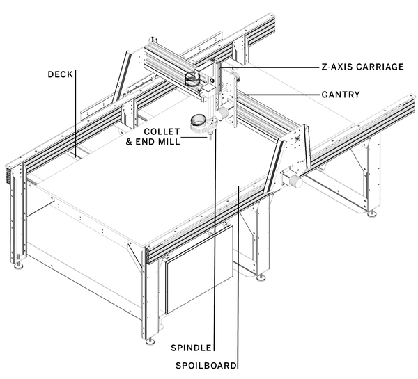
Figure 6-3. ShopBot PRSalpha 96″ × 48″ with annotations of key elements
Safety
Routing has some inherent dangers: machines have moving parts, bits can break, and chips and other particles become airborne. It’s best practice to always wear safety goggles and a proper dust mask (if your shop doesn’t have a dust filtration system). Plus, routers are loud when cutting, so wear ear protection. Spinning spindles can catch and pull in anything that hangs loosely on the body, so always remove jewelry, especially necklaces, and tie back long hair and roll up your sleeves.
Workholding Strategies
In order to cut the material, it needs to be secured to the machine bed. There are two basic ways to hold down material: mechanically secure it to the bed, or use a vacuum system. Your workholding strategy is important to consider up front; hold-downs are physical objects that you’ll need to factor into your design and cut files. Mechanical hold-downs, for instance, must be placed outside of the path of the spindle and gantry, as collisions can cause tool and machine damage. Decide on a strategy early in your design process and keep it in mind when preparing the cut sheet.
Screws and Clamps
Mechanical hold-downs are off-the-shelf items like screws and clamps. Screws are the easiest and most common way to secure large sheets to the sacrifice sheet. They don’t take up much space, and they can be driven in flush with the material being cut. As you cut sheets of 4′ × 8′ plywood for the projects in this book, it’s best practice to add a screw at each of the corners and then add additional screws approximately every two feet around the perimeter of the sheet. Carefully place the screws as close to the edge of the material/machine as possible, so you’ll be able to leave a 1″ margin around your cut files and be confident that you won’t hit any screws when machining.
Clamps are very useful when working with smaller size materials, or when you’d prefer not to mar your workpiece with screw holes. However, clamps have one key disadvantage: they protrude above the workpiece. This means that you’ll need to account for them both in your design and the toolpaths you create to avoid hitting the clamp with the machine.
Finding Safe Hold-Down Locations
Prior to cutting your actual design files, find safe locations for screws and clamps in your CAD/design files and then create a very shallow marking toolpath that creates “dimples” to mark hold-down locations on the sheet. After you run the marking toolpath, you’ll clearly see the safe locations for adding screws or clamps.
Vacuum Systems
A vacuum system uses suction to secure material to the machine bed, enormously simplifying the cutting process. It eliminates the need to dedicate material to mechanical fasteners and to plan toolpaths around them. Most significantly, it speeds up the process of taking material and parts on and off the machine.
There are two types of vacuum hold-down systems: conventional and universal. Conventional systems are usually specific to a particular task or process and utilize a small machine area, where a universal system utilizes the entire machine bed and is applicable to a broad range of applications. When we mention a vacuum hold-down in this book, we’re talking about a universal system. Although typically more expensive, they are well suited to jobs that make through cuts in sheet goods.
A vacuum hold decreases the more through cuts you make. You’ll want to limit the amount of small parts and cut them first, while you have more pressure.
Figure 6-4. Bill Young’s shop with its ShopBot PRS Alpha CNC router and vacuum hold-down system

End-Mill Anatomy
A router bit is a type of end mill. These terms are more or less interchangeable, but there are individual attributes that make a tool optimized for cutting a specific material.
The term end mill has a milling/machinist origin, and mills existed long before there were routers. Because routers and high-speed spindles spin at dramatically higher RPM than traditional mill spindles, machinists created modified end mills for routing wood without burning it up and starting a fire. These mills were capable of cutting at higher spindle speeds, and were subsequently dubbed router bits.
Fortunately, both end mills and router bits share common anatomical features, so knowing their parts will help you focus on the features that most impact your project.

Figure 6-5. Key parts of an end mill
- Tool Materials
-
End mills come in a variety of materials. Tools made of solid carbide are more expensive, but yield the best finish, have the longest life, cut quickly through material, and plunge well. Less expensive carbide-tipped and high-speed steel (HSS) tools tend not to perform as well and prove to be less durable.
- Flute
-
The radial or helical grooves machined into a tool. Each flute has a sharp cutting edge (or tooth) that cuts and then evacuates chips. End mills with one, two, or three flutes are used in woodworking, with two flutes being the most common. Tools with four or more flutes are typically used to mill harder substances.
- Shank
-
The plain region without flutes that is inserted into the spindle. Shank diameters come in standard sizes, the most common are: ¼″, ½″, and 1⁄8″.
- Cutting Edge Length
-
Abbreviated CEL, this refers to the part of the tool that has flutes and teeth and is able to cut material. Also called length of cut, LOC, or LC. The cut length of an end mill determines the maximum depth of cut (see “Depth of Cut”).
- Cutting Edge Diameter
-
Also called CED, this is the diameter of the cutting edge length (CEL). It determines the minimum feature size, or the smallest physical detail that can be created when using a specific tool.
Shank (SHK) and cutting edge diameter (CED) are usually the same, but they can be different, especially on smaller diameter tools. For example, you can have a tool with a ¼″ SHK and a 1⁄8″ CED. See Figure 6-12.
- Overall Tool Length
-
The overall tool length, or OAL is comprised of both the cutting edge length (CEL) and the shank (SHK). It determines how far the tool can protrude from the spindle in the z-axis direction.
- Deflection
-
It’s important to select the shortest overall tool length with the largest possible diameter. The farther a tool protrudes from the spindle, the more it will deflect, or bend and flex, as cutting forces are applied. While a small amount of deflection always occurs when machining, pushing a tool too hard (especially smaller diameters) can create oddly angled cuts, dramatically shortened tool life, dulling, and increased breakage.
Collets
A spring collet is a flexible type of chuck, or tool clamping system intended to hold a cylindrical object. The collet is part of the spindle assembly. The tool is inserted into the collet and then tightened with a collet nut that compresses it tightly around the inserted tool.
Like end mills, collets also have dual diameters. They come in standard sizes with an exterior measurement that matches the CNC’s spindle and an interior measurement that corresponds to a tool’s shank.
End-Mill Geometries
Pairing your material and machine setup with the proper tool is vital, but it can be a challenge; there are an immense variety of cutter types and shapes available for every conceivable material and cut type. But don’t worry, we’ll walk you through the basic principles and tool types—and provide tool recommendations for routing plywood with part numbers and suppliers to get you started.
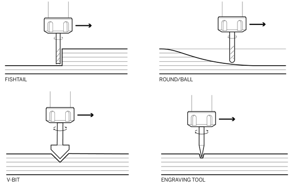
Figure 6-6. Tool end types
End Types
End mills for machining wood have two basic end types: those that are able to plunge straight into material, and those with flattened end flutes that must be ramped in.
- Standard/Plunge End
-
These tools are sometimes called fishtail or swallow tail end mills, due to the indentation at the end of the tool. These tools work well for both profile and pocket cutting. For profile cuts, it produces a completely flat edge surface. For pockets, it leaves a clean, 90-degree angle between the side and the bottom, and gives the bottom of the pocket a flat surface (for further details, see “Pockets”).
- Finish/Flat End
-
The fishtail-style plunge end mill can leave toolmark scratches in the bottom of a pocket, which can be eliminated by using a finish or flat end mill (FEM), which must be ramped into the cut due to its much flatter end.
- Ball-nose
-
A ball-nose end mill has helical flutes and a round end, which is best for contour cutting, and is capable of creating topographic smoothness because its ball end makes minimal contact with curved surfaces.
- V-Bit
-
A v-bit has an angled tip that carves a deep v-shaped groove into the material surface. Typically the sharp bottom of a v-bit is aligned with the toolpath, making it ideal for v-carving, or cutting decorative details with a three-dimensional effect without the need for an actual 3D model. V-bits come in a variety of angles and depths, depending upon your desired depth and width of cut.
- Engraving
-
Engraving tools make a shallow cut along a toolpath. They are capable of etching very fine, often decorative, details into a surface.
Flute Types
End mills for machining wood have radial or helical flutes. Radial flutes are straight grooves that are parallel to the tool’s axis, while helical flutes wrap around the tool.
Higher helix angles clear chips away from the cutting edge faster. Straight tooling with radial flutes have a 0° helix angle, while spirals for cutting wood can have a helix angle of up to 35°. In addition to high helix angles, router bits also have steeper rake (tool attack angle) and clearance angles to evacuate the chips much faster than a traditional end mill.
As the tool turns, the direction of the spiral determines which way chips are ejected. The two basic types of helical end mills are upcut and downcut, shown in Figure 6-7.

Figure 6-7. An upcut tool pushes chips up and out, while a downcut tool forces them down into the kerf, as it cuts
Stay away from left-hand rotation tools, often indicated with an “L” or “LH” in the tool number. They are meant for spindles that rotate counterclockwise.
- Upcut Spiral
-
This tool’s flutes eject chips upward, out of the gap created between the cut piece and the waste material (kerf). Because the chips are forced up, the material’s top surface can become chipped or frayed (known as tearout), while the bottom face will be cleanly cut.
Although upcut tools are very efficient at dissipating heat and clearing chips, they have some undesirable effects that can make them a poor choice for routing plywood. The upward chip movement pulls the material up from the cutting bed, creating a troublesome lifting effect on lighter, thinner materials. This movement can also pull at small cut parts and long skinny parts. This can be problematic for vacuum holdowns, and you’ll need to use tabs to keep parts in place.
- Downcut Spiral
-
A downcut spiral’s flutes push chips downward, toward the machine bed. When cutting with ¼″ and 1⁄8″ downcut tools, the chips can become compacted in the kerf, which helps to hold the material against the CNC machine bed.
When through-cutting, the downward force created by the chip ejection can cause tearout on the bottom face, while the top face will have a nice finish.
Don’t drill with downcut tools. It’s already hard to clear chips when drilling, and pushing the chips down into the hole further exacerbates this problem.
- Compression Spiral
-
A compression tool is a combination of an upcut and downcut spiral. It pulls material up from the bottom of the cut and down from the top of the cut, leaving a good-quality finish on both the top and bottom faces. This seems ideal, but compression tools are expensive, and most are meant to cut in one pass at full depth.
- Straight Flute
-
These radial two flute tools have a zero-degree angle and create a superior finish in natural wood and wood composites. The entire straight flute makes contact with the material when cutting. Chips are not pushed up or down, creating a good edge quality on most materials.
Straight flutes are Bill Young’s tool of choice for routing Baltic birch plywood.
Not all router bits can run at the highest available router/spindle RPM. The tools we recommend are safe at high speeds, but you should be aware that large diameter tooling, especially cheap, low-quality bits, may be unsafe to run at max RPM. Refer to manfacturer documentation for safe speeds.
Feed Direction
Material is often fed into machines—for example, you feed fabric into a sewing machine, wood into a table saw, or metal into a stationary milling machine spindle. But when routing, either with a hand router or a gantry-style CNC router, it’s the opposite—you feed the spinning tool into stationary material.
Feed direction determines which way the tool moves around the part when cutting and how the tool’s clockwise-rotating flutes create chips when they make contact with the material. This impacts the edge quality of your cut parts.
As illustrated in Figure 6-8, a conventional feed direction cuts a closed part in a counter-clockwise direction, while climb cutting moves clockwise around a part’s perimeter.
Conventional Cutting
With conventional cutting, the primary cut is made as the tool exits the material. The chip starts out thin and then ends thick. This can cause end-grain splintering in hardwoods, but it works well for composite sheet goods, like plywood.
This scenario is safer on a table or hand-held router, and because hand-held routers paved the way for CNC tools, this cut type is considered to be the “conventional way.”
Climb Cutting
In a climb cut, the chip starts thick and ends thin. This can result in a smoother cut in materials such as hardwood because it eliminates end-grain splintering. However, the forces created can also mar the finsh and push parts around due to the bit trying to “climb” out of the cut. In addition, the forces created can deflect the tool.
Conventional (counterclockwise) and climb (clockwise) feed directions are reversed when pocketing or cutting the interior of a part. When making interior cuts, a conventional feed direction will move clockwise, and a climb cut will move counterclockwise.

Figure 6-8. Climb versus conventional
Feed Direction Strategies
Although we’re recommending a conventional cut for plywood, this isn’t gospel. Machining advice is always specific to the exact materials and tooling you’re using. Plywood varies greatly between brands, types, and even between batches. Sometimes climb cutting may work better than conventional.
The key is to jump in and test your material/tool pairing and settings. Always cut in the direction that gives you the best finish. Cut some test pieces and look at both the part and the scrap/waste material. If the scrap looks better than your cut parts, reverse the feed direction.
You can also try using an onion-skin strategy. This is a machining methodology that utilizes the strengths of both climb and conventional cutting. First, climb-cut the part, but leave a thin “onion skin” layer behind. Then cut the final pass as a conventional cut.5
Ramp Moves and Tabs
Although center-cutting end mills can plunge straight into the workpiece when beginning a toolpath, it’s hard on the cutter and leads to premature wear—while it is possible to drive them axially into your workpiece that doesn’t mean you should.
Ramp moves are a much gentler way to ease the tool into the material. Ramping in at a gradual angle reduces heat buildup and spindle/z-axis load, plus it helps to reduce vibration and keeps parts in place while machining. Because you’re slowly ramping into the cut, keep your plunge rate, or axial cut rate, the same as your feed rate.
Smooth Ramps
Smooth ramps work well for easing the tool into large parts. Because center-cutting bits have flutes on both the sides and bottom, and three-axis CNCs can move in the x, y, and z axes at the same time, it’s possible to gradually and smoothly move the rotating tool into material at an incline, as shown in Figure 6-9.
Spiral Ramps
This ramp type slowly eases the tool into the material over the full perimeter of a profile toolpath. Spiral ramps are particularly useful for small parts because machining forces can push them around as they are being cut. If the part becomes dislodged from the main workpiece, it will get caught up by the moving tool, resulting in ugly gouge marks in the part, which can also fly off the machine bed. This is bad for safety, your parts, and your end mills, which can break. Spiral ramps also help to maintain vacuum hold because they help to keep parts from lifting.

Figure 6-9. Smoothly ramping into cut
Tabs
Tabs are small, rectangular sections of uncut material, added to profile toolpaths in CAM software, that keep a part joined to the waste material when making through-cuts. Tab length, thickness, and placement are usually user configurable. Also called bridges, tabs are helpful for keeping small parts in place or long, thin parts from vibrating, especially if you don’t have a vacuum hold-down system.
Pratical Tab and Ramp Advice
For most large parts, I use a four- to six-inch smooth ramp into the cut, but with really small parts (like feet) and holes I use a spiral ramp. On small parts, I also use a single tab at the start point of the cut and move the start point so that it’s on a straight side that’s parallel to the grain. I rarely use tabs on large parts unless they are long, thin, and want to vibrate, and then a couple of tabs help.
Bill Young
Pockets
Pocket cuts have vertical sides and a flat bottom and can be used to create a recessed area for anything you can imagine, from joinery connections to adornments. Pocket toolpaths are similar to inside toolpaths; they both cut on the inside of a closed line, but pockets also remove all the material inside the cut line to a specified cut depth.
If you’re familiar with the traditional hardwood slot creation techniques of grooves, rabbets, and dados, you can think of a pocket as the “Swiss Army knife” of CNC slots. If you’re attempting to translate a woodworking design created by more traditional means for CNC sheet goods, woodworking slots (grooves, dados, and rabbets) are defined in terms of how they run with or cut across the grain. However, because plywood is made from individual sheets turned at right angles and glued together, it doesn’t have a singular “grain” like hardwoods do.
When clearing pockets, there are two basic ways to remove the material: offset and raster.
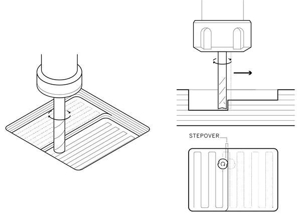
Figure 6-11. Multiple views of cutting a pocket via the raster method and showing tool stepover
Raster
A raster pocket begins at one end, and the tool moves side to side from one end of the pocket to the other, clearing out a recessed area, as shown in Figure 6-11.
When pocketing visible designs or features, rastering with the grain can help hide toolmarks in wood. However, grain direction when pocketing is more relevant when working with hardwood than plywood. With plywood, you’d need to determine what ply your cut depth will reach, and which way the grain is rotated, a tricky proposition.
Stepover
The amount of tool overlap between passes is called the stepover value. The smaller the stepover percentage, the finer the finish due to the increased toolpath overlap. A stepover value of 50.0%, or one-half the diameter of the bit, is usually enough to minimize tool marks and leave a smooth bottom surface.
Depth of Cut
Depth of cut, also called pass depth or depth per pass, is how deep each individual machine-cutting pass should be to reach the cut depth. It often takes several passes to cut all the way through material.

Figure 6-12. Pass depth for ¼″ tool versus smaller 1⁄8″ tool
Depth of cut is determined by both material thickness and end-mill diameter. When cutting with small diameter tooling (1⁄8″ and smaller), it’s best to make shallower passes than when using ¼″ and larger diameter tools.
The general rule for determining depth of cut is that one pass should equal the diameter of the end-mill. So, as shown in Figure 6-12, a ¼″ end mill takes three passes to cut through a ¾″ sheet of material or two passes for ½″ material.
Making more passes takes more time, but makes a cleaner cut and puts less stress on your tool. Increasing cut depth by too much can lead to poor cutting quality, as well as end-mill breakage. Experienced fabricators often push cut depth to the limit to save time by reducing the number of passes. However, beginners and those with few tools might want to err on the conservative side.
Both depth of cut and tool diameter have an effect on chip load. When depth per pass exceeds a tool’s diameter, the chip load becomes greatly reduced. If your cut depth is greater than two times the tool’s diameter, the chip load is reduced by 25%. If you cut deeper still, to three times the diameter, it’s reduced by 50%.
Putting It All Together
Material properties are the primary factor driving your machining decisions. Knowing how to properly combine machining variables with your tool choice allows you to efficiently cut parts with clean, smooth edges, regardless of a material’s hardness or thickness. To produce quality parts in a reasonable amount of time, it’s critical to consider cut depth and feed direction and to optimize the end-mill geometry with feeds and speeds that produce the correct chip load.
As it cuts through material, an end mill produces a tremendous amount of heat. If allowed to build during machining, this heat will actually dull the tool, or worse, cause it to break. In order to prevent tool failure. This heat must somehow be dissipated.
An end mill is ingeniously engineered to rely upon the very chips it is cutting to evacuate heat and to sustain an operable temperature. In CNC machining, there is a sweet spot where tool geometry combines with feed-and-speed settings to remove chips at a rate that effectively dissipates this heat.
When you find this sweet spot, your machine runs smoothly and even quietly, without chatter or vibration. Your parts come out with very smooth edges that need a minimal amount of sanding or filing. Test pieces are helpful in finding the right balance. You can easily cut multiples of them to test various setting combinations.
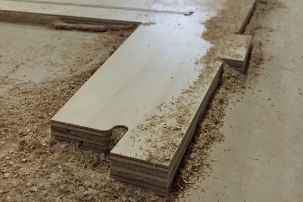
Figure 6-13. Well-formed woodchips have a slight curl
Troubleshooting
We recommend using the AtFAB project test pieces, introduced in “Test Pieces” and downloadable from the book’s website, to dial in your feeds and speeds. The test pieces are small, and because you’re already using them to fine-tune joinery fit prior to cutting the full-size project file, they’re also perfect for ironing out machine settings.
If your cuts have a rough surface finish or your bit broke halfway through cutting a part, double-check your CAM settings first, especially the number of zeros (speeds) and the decimal points (feeds). Chapter 7 will explain how to import a design file and create toolpaths in a CAM program.
After checking the numbers, or if you’re using the CAM defaults, here are some tips on how to dial in your feeds and speeds using chip load as a guide.
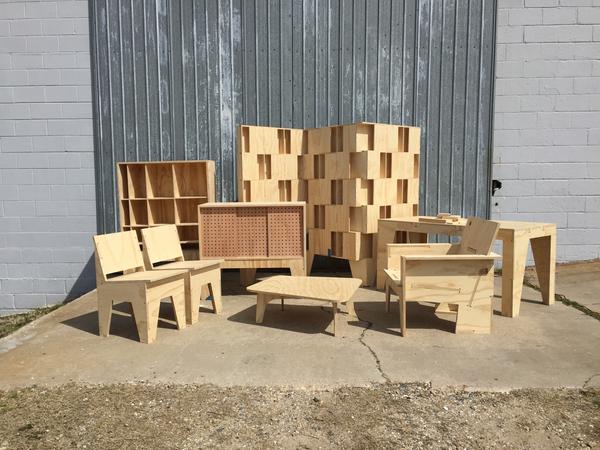
Figure 6-14. AtFab furniture projects machined by Bill Young, assembled and photographed by Gary Rohrbacher
- Check Your Chips
-
After cutting a test piece, take a look at your chips. As shown in Figure 6-13, well-formed chips often have a curl to them. If they look like fine dust, then they’re too small, and your feed rate was too fast.
- Feed a Screaming Bit
-
If the machine emits a loud, high-pitched noise, or scream, as it cuts through the material, it is “hungry”; feed it by increasing the feed rate.
- Cool Tool Test
-
A tool with a feed rate that is too fast will be warm—or even hot—to the touch. After cutting a part, wait for the machine to come to a complete stop. Tools can get hot enough to burn you, so touch the bottom of the spindle first. If the spindle isn’t noticeably hot, touch the tool shank. If the tool is at room temperature, then your feeds and speeds are properly dissipating heat.
- Bracketing the Feed Rate
-
When you’re having trouble dialing in your settings, always adjust your feed rate first. A process that can help is similar to bracketing in photography. Keeping the speed the same, increase the feed rate until the part finish deteriorates; then back off and decrease the speed by around 10%.
- Feeding Too Fast
-
When a feed rate is too fast, the end-mill evacuates chips too quickly. This rapid removal prevents chips from having enough contact with the end-mill to absorb its heat. This reduced contact causes the tool to retain heat and ultimately fail. Decreasing the feed rate slows the speed of the tool along the toolpath. This decrease in feed increases the duration of contact between the end-mill and chips, so the chips adequately absorb heat before they are ejected.
- Feeding Too Slow
-
When the feed rate is too slow, the chip evacuation doesn’t keep up with the chip formation. These chips retain heat, and this buildup of heat, in combination with the forces of feed, will break your bit. Increasing the feed rate will move the end-mill more quickly along the toolpath, so that the rate of evacuation keeps up with the rate of chip formation.
Don’t be afraid of pushing the feed rate; it’s good to keep the tool moving quickly through the cut. Most bit breakage comes from cutting too slowly.
- Decrease Cut Depth
-
Cut depth is another factor that can lead to suboptimal machining. First, double-check your settings, because it’s easy to enter the incorrect numbers or put a decimal point in the wrong place. If your depth of cut is agressive, then dial it back to match your end-mill diameter.
- End-Mill Flutes
-
As the number of cutting edges increases, your feed rate should increase to prevent burning and premature tool dulling. Using more flutes reduces chip load and improves surface finish, if the feed rate remains the same.
- Spindle Speed/RPM
-
You rarely need to adjust your spindle speed. That’s probably around 12,000 RPM when cutting plywood with a ¼″ diameter two flute tool. It’s typical to pick a speed that works for your material and then adjust the feed rate accordingly, using the formulas in “Machining Variables”. However, speed is another variable that you can consider. When the chip load is too large for your tool to handle, decreasing the RPM will reduce the rate of chip formation. Alternatively, you can increase your spindle RPM to allow the tool to form chips more quickly.
In the next chapter, you’ll get hands-on with CAM software, where you’ll be able to import files, define toolpaths, and run machining simulations.
1 A Google image search for “Bridgeport mill” will give you an idea of what an old-school, knee-and-column mill looks like.
2 PRS or Personal Robotic System
3 Under the hood, ShopBots are configured in inches per second. Either way, feed is still length traveled per time elapsed.
4 Onsrud data compiled by ShopBot and Centurion Tools
5 Router Bit Basics for CNC by Steve Glassel describes the process in detail, see Appendix A.