
Chapter 7. Modeling Software to Machine
Computer-aided manfacturing or CAM software is where the virtual design converges with the physical material and machine. In the past, programming toolpaths and operating CAM software were the realm of expert machinists. Recently, however, there’s been an explosion of affordable, user-friendly CAM programs to set up your project for fabrication. “Programming toolpaths” is now far simpler than it sounds. Rather than write code from scratch, modern CAM software interfaces help you create cutting definitions for the parts you want to machine.
From CAD to CAM
As introduced in Chapter 2, a CNC uses a specialized tool called an end mill to cut and carve a digital design. The machine follows user-defined toolpaths, or instructions, that tell it where and how deep to cut. In Chapter 3 and Chapter 4, you went through the process of laying out and organizing parts into SketchUp components, and assigning 2D profiles to toolpath layers. Now you’ll create actual CNC toolpaths in a CAM program.
This chapter introduces CAM fundamentals, walking you through file setup and toolpath creation in VCarve Pro, using the AtFAB Rotational Stools SketchUp file. You’ll learn the principles and practices of file setup, toolpath settings, and machining simulation that are essential to the pursuit of digital craftsmanship.
Digital/Physical Alignment
Machining your files is exciting; your digital dreams are about to become real objects! However, when the tidy virtual space meets reality, things can get a little messy. CAM software is where your digital “model space” meets the physical properties of your machine and material.
CAM programs are organized to help you manage the transition from digital file into reality. Before you begin importing the digital information, it’s critical to first identify the physicalities of both your machine and your material. Know the dimensions of your machine bed, as well as the length, width, and thickness of your anticipated sheet material. It’s also key to locate the XYZ origin (Figure 7-2) and orientation of the machine bed, as well as its default units. With these physical attributes identified, you are ready to start setting up a CAM file that coordinates physical machine and material with the digital information in your CAD file.
Units
When you transition from designing to machining, you inevitably export and import files across multiple programs. It’s a good practice to pay attention to the unit settings in your file and familiarize yourself with import/export settings in your CAD and CAM software. Mixing units can cause trouble with parts that scale to the wrong dimensions or cause your machine settings to go wildly off.

Figure 7-1. Digital CAD file origin in “model space”

Figure 7-2. Machine origin on a ShopBot PRS Alpha CNC router
The digital/physical alignment process becomes much clearer and easier once you’ve become acquainted with the toolpath creation process as well as the specific machine you’ll be using. It’s best practice to always set up your CAM files to correspond to the bed size, orientation, and origin of the physical machine you’ll be using to cut those files. This enables you to machine with confidence, because you know exactly where the tool will cut.
VCarve Pro
After working with many CAM programs over the years, we have grown to appreciate VCarve Pro for many reasons. Created specifically for CNC routing (not milling), it has a SketchUp plug-in that allows smooth imports, but also has the ability to open massive DXF files with ease—never crashing or choking. VCarve excels at creating and tracking the multiple toolpaths necessary for machining the projects in this book.
VCarve is widely used and easy for beginners to learn, but full-featured enough for experts. In addition, its interface changes very little between software upgrades, and there’s a free trial version available. The one drawback is that it only runs on Windows. However, don’t let that discourage you, as there are plenty of workarounds for Mac users (see “CAM Workarounds for Mac OS”).
Currently, the VCarve Pro “trial” is actually a limited version of the full software package. The trial doesn’t expire, but you’re constrained to saving your work in Vectric’s .CRV file format, and you won’t be able to send the toolpaths you create to a physical machine. That’s completely fine for the purposes of this book, because if you already have your own CNC—or have access to one in a shared shop—that machine will already have a CAM software toolchain in place. The toolpath creation principles will remain the same, regardless of software.
Download and Install
-
If you don’t already have Vectric’s VCarve CAD/CAM software, download and install a free trial from the Vectric site. For this project, you’ll need the Rotational Stools (Figure 7-3) SketchUp file (ATFAB_STL_D4CNC.skp), which can be found on the book’s website.

Figure 7-3. The Lazy and Lively Rotational Stools and vectors
This file, like all project files for this book, was organized and saved as SketchUp 2014 using the same process you followed in Chapter 3. When you open the file in SketchUp, you’ll find the 2D part profiles placed onto toolpathing layers, with individual parts and the overall cut file grouped into SketchUp components. You’ll also find a fully modeled version of the Rotational Stools on 3D modeling layers.
Chapter 8 will walk you through the process of fabricating the stool parts from your finished CAM file. If you already have your material—and want to fabricate the stools after completing this CAM setup exercise—you’ll need to scale your CAD file to match your material’s thickness (TMAX). Refer to “Measure Your Materials” and “Scale Your CAD File” for details. If you’re not ready to fabricate, proceed through this exercise with the CAD file as it is.
This exercise walks you through key steps of setting up a CAM file and creating toolpaths for the AtFAB projects. For software help, you’ll find an extensive manual within VCarve Pro itself (Help→Help Contents) that offers detailed information on VCarve’s commands and features. It also provides links to Vectric’s video training resources at http://support.vectric.com.
Open VCarve and Create a New File
-
Open VCarve Pro. You’ll see a blue sidebar to the left of the blank main window, in Figure 7-4.
-
Create a new file by selecting the “Create a new file” option from the startup screen; you can also simply click File menu→New or enter the keyboard shortcut Ctrl + N. Your new, blank file will look like Figure 7-7.

Figure 7-4. Open VCarve Pro
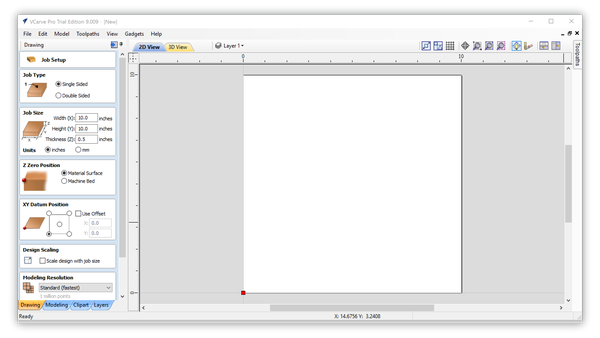
Figure 7-5. New file opened in VCarve Pro trial edition 9.009
Job Setup
When setting up a new file, VCarve Pro prompts you to set up the job size, material thickness, position, origin, units, scaling, and modeling resolution and color options. Because other operations actually depend upon these settings, VCarve Pro (helpfully) prevents you from going further until you verify that your file is set up to match your actual machine and material.
Next, you’ll begin to align your digital file with physical reality by setting up your workspace to match your sheet material and machine cut area.
Use default Job Setup options
You’ll use the default VCarve Pro setup options for most of this exercise, but we go through the process of explaining what to enter to clarify and explain the settings.
Job Type
Selecting a Job Type (Single Sided or Double Sided) is the first step in setting up a VCarve Pro file. It also determines what settings are displayed. When you cut the AtFAB projects from this book you’ll be routing single sided jobs.
-
Keep the default setting, Single Sided, as shown in Figure 7-6.
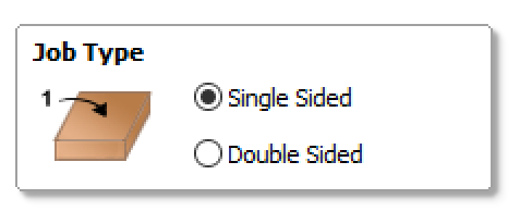
Figure 7-6. Job Type

Figure 7-7. New file with default job setup options
Job Size
The Job Size matches the actual dimensions of your material; this exercise uses a 4′ × 8′ × ¾″ plywood sheet. The units should match the default units of your CNC machine. While Width (X) and Height (Y) can be generalized, Thickness (z) must be the actual measured thickness of your sheet material, or TMAX from “Measure Your Materials”.
-
Enter 48.0 inches for Width (x) and 96.0 inches for Height (y), as shown in Figure 7-8.
-
Enter TMAX in Thickness (z) field.
If you’re working through the exercise, without plans to machine immediately, enter TNOM—the nominal value of 0.75 inches—in the Thickness (z) field.
-
Select inches, as shown in Figure 7-8.
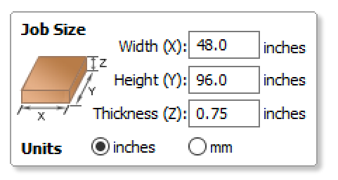
Figure 7-8. Job Size
Z Zero Position
The default Z Zero option sets the z-axis origin to the surface of the material. It’s also possible to set Z Zero to the surface of the machine bed. (“Pocket Cutting: Top Down or Bottom Up?” elaborates on why you would do this.)
-
Keep the default Z Zero option selected (Material Surface, as shown in Figure 7-9.
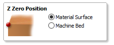
Figure 7-9. Z Zero Position
XY Datum Position
A datum is a fixed starting point of scale or operation. The datum position is intended to correspond to the machine’s origin or (0,0), which is usually set separately using machine-specific control software, but can be offset in CAM. Offsetting shifts the origin of your CAM file by a specified (x,y) amount relative to the machine bed size. Since the digital files you’re using are mapped to a full sheet, you don’t want to offset.
-
Keep the default datum options selected, shown in Figure 7-10 (unless your CNC is configured differently); “Use offset” should be unchecked.
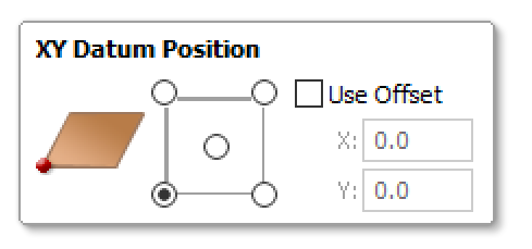
Figure 7-10. XY Datum Position
Design Scaling
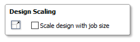
Figure 7-11. Design Scaling
This option scales the entire size of your file relative to the Job Size (X & Y) values you entered in “Job Size”. That’s problematic for parts that were designed and scaled in CAD to be dimensionally accurate.
-
Keep the default, making sure the box is unchecked (Figure 7-11).
Modeling Resoluton

Figure 7-12. Modeling Resolution
The modeling resolution and appearance settings are purely visual and have no effect on the toolpaths themselves.
-
Keep the default settings shown in Figure 7-12.
Complete Setup
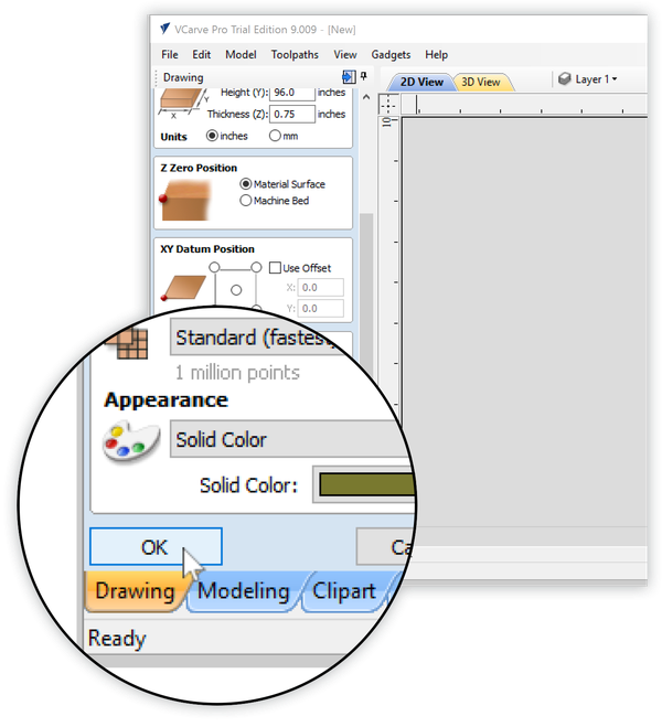
Figure 7-13. Click OK to complete the Job Setup
-
When finished, click the OK button at the bottom of the Job Setup panel, shown in Figure 7-13. The Job Setup options will automatically be replaced by the drawing panel.
After you configure your Job Setup once, VCarve Pro will remember your selections and entries. They’ll be there each time you create a new file—but you’ll still need to click OK to confirm them every time.
If you ever need to access the Job Setup menu after setup, you can reach it through the Edit menu→Job Size and Position.
Importing Vectors
With the job setup complete and physical parameters defined, you’re ready to import the Rotational Stools SketchUp file.
Download the Rotational Stools files from the book’s website. You’ll need ATFAB_STL_D4CNC.skp for this exercise.
Import Stools SketchUp File
-
Choose Select File→Import Vectors from the top menu and then navigate to the ATFAB_STL_D4CNC.skp SketchUp file you downloaded.
The SketchUp File Import window (Figure 7-14) opens with several settings to choose.
Layout of Imported Data
Think back to when you were organizing the last step of “Save as SketchUp 2014”; after all the “part components” were laid out onto the cut sheet, you grouped them all into a final, single group. The Rotational Stools file has also been organized this way.
All project files in this book have been organized this way, just like the Chair example.
Grouping components prevents VCarve’s Auto Orientate feature from automatically re-laying out parts. When factors like grain direction and alignment matter, as explained in Chapter 3, manually arranging parts onto the sheet is preferable to depending on Auto Orientate to do the job alone.
-
Choose Exploded Flat Layout and Auto Orientate under Layout of Imported Data.
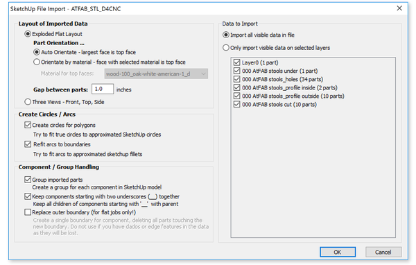
Figure 7-14. SketchUp File Import window detail
Create Circles/Arcs
- Create Circles for Polygons
-
Since SketchUp segments circles, this setting changes circles into polylines. This that ensures the CNC machines smooth circles for holes rather than faceted shapes.
- Refit Arcs to Boundaries
-
Similar to Create Circles for Polygons, this setting turns segmented arcs, particularly in sniglets and other types of corner fillets, to approximate SketchUp arc fillets. This keeps sniglets smooth rather than faceted.
-
All boxes should be checked under Create Circles/Arcs.
-
Component/Group Handling
- Group imported parts
-
For Component Handling, choose this setting to keep all SketchUp components grouped.
- Keep components starting with two underscores (__) together
-
In addition to the component handling setting, this option ensures that each component in the SketchUp file acts as a single part in VCarve. This setting allows toolpaths common to one part, but assigned to separate layers, to remain together.
You may recall using this double underscore convention to name your components in SketchUp, as we did in “Make 3D Parts into 2D Profiles”. That step ensured that these SketchUp components were imported as distinct parts in VCarve.
-
Select the first two options only, “Group imported parts” and “Keep components starting with two underscores (__) together” under Component/Group Handling.
Data to Import
Because the Rotational Stool file was saved with only its toolpathing layers turned on, you want to select “Import all visible data in file.” The other option that imports visible data on selected layers is helpful if you want to import particular layers.
-
Choose “Import all visible data in file” under Data to Import. All the boxes should be checked.
-
Click OK to import the file. The imported file will look like Figure 7-15.
Vector and Layer Adjustments
Importing one file format into another is always a little tricky, and as you’ve seen from all the conversion settings, there are many things that can go wrong. Once you’ve imported your SketchUp vectors, it’s helpful to check over all of the settings, vectors, and layers.
Distinct parts should appear, just as they did in SketchUp. Ensure that the vector layout in the main VCarve window matches the screenshot shown in Figure 7-15. The cut file outline should match the Job Size and orientation.
The workflow from SketchUp into VCarve typically requires a few additional adjustments. These next steps will walk you through these adjustments of aligning the cut file to the material stock, ungrouping vectors, and joining open vectors.
Align Cut file to material stock
-
If the sheet material outline does not align with the sheet in the main VCarve window, select all vectors in the file (either with the cursor or Ctrl + A).
-
Click the Align Tools option from the Drawing Toolbar→Transform Objects→Align Selected Objects icon, shown in Figure 7-15. This will align the entire cut file with the material stock that you just defined in the Job Setup.
-
Close the Alignment Tools by clicking the Close button at the bottom of the palette (Figure 7-17). You may need to scroll down to the bottom to see it.
-
Save your file as a VCarve file or CRV. Name it Rotational-Stools.crv.
When working in the blue sidebars, you’ll need to click a “Close” button at the bottom. Just like you had to click “OK” to get out of the Job Setup menu, you’ll need to click “Close” to deactivate the Drawing palettes that open up.
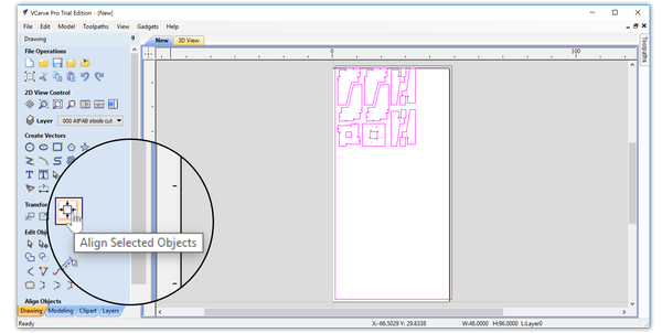
Figure 7-15. Rotational Stools file in VCarve Pro, use Alignment Tools to correct sheet misalignment.

Figure 7-16. Alignment Tools palette open, vectors aligned to material

Figure 7-17. Alignment tools “Close” button
Ungroup Vectors
The technique of combining all 2D components within a single overall component in SketchUp preserves your cut sheet layout during import, but all parts will be grouped into a single layer as a result. On initial import, you’ll find that SketchUp layers will be black, rather than distinct toolpath layer colors, distinguishing inside cuts from outside cuts and holes.
If your file imports without its layer colors, you’ll need to release the group so that each part is placed onto its originally assigned cut layers. To ungroup parts back to their original layers:
-
Select all vectors, then from the Drawing sidebar go to Edit Objects → “Ungroup objects onto their original layers,” as shown in Figure 7-18.
-
Select only the parts; not the outside cut sheet border. Click the Zoom Selected icon, Drawing→2D View Control→Zoom Selected, to enlarge your view of the parts.
You can also ungroup by right-clicking and selecting Ungroup Objects→Ungroup objects back onto original object layers.
-
After ungrouping, the vectors take on the color of the SketchUp toolpath layers: blue for outside profiles, green for inside profiles, and red for holes (Figure 7-20).

Figure 7-18. Ungroup objects back onto their original layers
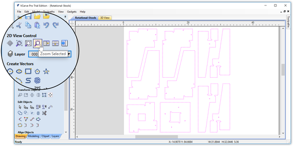
Figure 7-19. Select only the stools vectors and then Zoom Selected
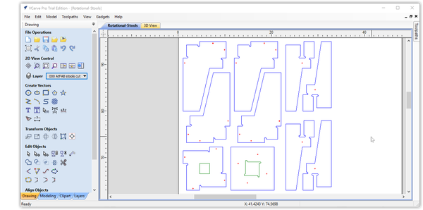
Figure 7-20. Ungrouped vectors return to their SketchUp layer color
Join Open Vectors
VCarve toolpaths work best when they’re created from closed vector shapes. Diligently grouping vectors while in SketchUp usually ensures that your imported file will have closed vectors, but sometimes things don’t go as planned.
It’s possible that your part vectors are not joined together, but are individual lines in places. Luckily, VCarve has a “Join Vectors” operation that lets you quickly identify open vectors and close any open, unjoined vectors that you may have imported.
-
Check for open vectors by Edit → Select All Open Vectors. If any are open, it’s easiest to fix them one layer at a time.
-
Turn on the blue layer, Profile Outside, and turn off all other layers.
-
Select all elements on Profile Outside choose Drawing → Edit Objects → Join Open Vectors.
-
Repeat this process with the Inside Profile and with other layers.
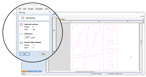
Figure 7-21. Joining the open outside profile vectors
You can also select all by using Ctrl + A and then hitting J to bring up the Join menu.
Creating Profile Toolpaths From Vectors
Each profile toolpath has a unique combination of cutting attributes. “Toolpaths” explained how a tool could be programmed to cut inside, outside, and on the vector. Depending on where the tool cuts, relative to the vector, the kerf shifts position, and, in turn, changes the dimensions of the part.
Before you create the toolpaths for the Rotational Stools, take a look at Figure 7-22, which contains three identical squares drawn with identical dimensions. Each square is cut with a 1⁄8″ profile toolpath, each toolpath having a different relationshp to the drawn vector.

Figure 7-22. The same size, equally spaced boxes with outside, inside, and on line profile toolpaths applied
In Figure 7-22, the red line with black arrows visually represents the path the tool will travel to machine the part. Figure 7-23 shows a 3D machining simulation of the toolpaths.

Figure 7-23. 3D machining simulation of outside, inside, and on line toolpaths in Figure 7-22
The outside toolpath creates a dimensionally accurate part, while the inside toolpath cuts a correctly sized slot. The on vector cutting option is not dimensionally accurate as a slot or a part. Avoid cutting on the vectors, unless you are etching or cutting decorative embellishments.
Rotational Stools Toolpaths
ATFAB_STL_D4CNC.skp has three toolpathing layers. The vectors that outline each part are assigned to the Profile Outside layer, the square shapes centered in each of the seats are assigned to the Profile Inside layer, and the vectors that form the fastener holes are assigned to the Profile Hole layer.
Up to this point, you have been working with virtual vectors organized onto layers—let’s turn them into actual, physical toolpaths!
To cut out the Rotational Stool’s outer profiles, you need to assign the tool to cut on the outside of the vector, creating dimensionally accurate parts that will fit together well. Conversely, to machine the Stool’s inside profiles and fastener holes, the inner dimension is important, so you’ll assign an inside toolpath that will cut on the inside of the vector.
In addition to defining the relationship between the cut path and 2D vector, toolpaths also require four other inputs: tool diameter, cut depth, pass depth, and toolpath type.
In the following steps, you’ll be using the Toolpaths menu, shown in Figure 7-24 to create three different toolpaths to handle these different cutting requirements. As you define each toolpath, it’s helpful to take advantage of your layer organization. Use the Layers List palette to isolate and assign definitions to each toolpathing layer.
The Toolpaths menu is on the right; the Layers menu is on the left.
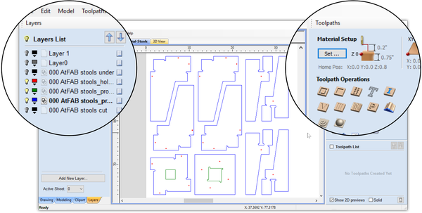
Figure 7-24. Layers List palette on the left side, and Toolpath Operations on the right
Fastener Hole Toolpaths
First, you’ll define toolpath settings for the fastener holes, sized for the fasteners that will be used to hold the parts of the stool together. These steps walk you through defining an inside toopath for a smaller 1⁄8″ end mill, which will cut all the way through the material.
Select Profile Toolpath Operation
-
Click the Toolpath tab on the right-hand side of the screen to open the Toolpaths blue side menu.
-
Turn on the Profile Holes layer and turn all other layers off.
-
Select all vectors on the Holes layer, Ctrl + A.
-
To define a toolpath type, select Toolpath Operations→Profile Toolpath to open the 2D Toolpath menu, as shown in Figure 7-25. Figure 7-26 shows the 2D Toolpath menu.
There’s a little thumbtack icon at the top right of both the blue sidebar menus. Click it to “pin” the menu open—or unpin it to increase the size of the file-viewing area.
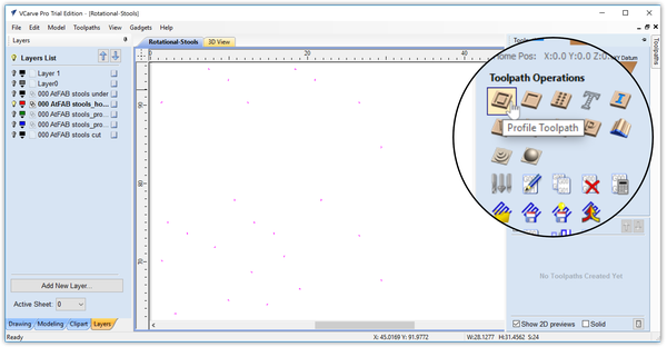
Figure 7-25. With the Holes layer isolated, select all vectors and click the Profile Toolpath icon
Open the Tool Database
-
Click the Select… button from the Tool section of the 2D Profile Toolpath menu, Toolpaths→2D Profile Toolpath→Tool, to open the Tool Database, as shown in Figure 7-27.
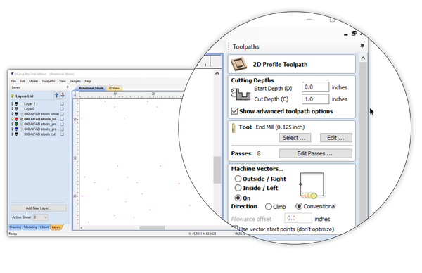
Figure 7-26. The open 2D Profile Toolpaths menu
Figure 7-28 shows the Tool Database pop-up window that will open over the main VCarve interface.

Figure 7-27. Tool selection from the toolpaths menu
Select 1⁄8″ Tool
VCarve has a long list of prepopulated end-mills in its Tool Database, as well as the option to define your own. Until you are fluent in CNC routing, it is fine to use the default settings assigned by VCarve.
-
Choose a 1⁄8″ diameter end-mill, Imperial Tools→End Mills→End Mill (0.125inch).
-
Click the Apply and OK# buttons. The Tool Database window will close.
This chapter provides a basic introduction to CAM by covering the basic process of creating profile toolpath options. Chapter 6 provides additional detail on feeds, speeds, and the machining process, but the focus of this book is on the design-through-fabrication process so that you can successfully fabricate the projects we cover.

Figure 7-28. Tool Database pop-up menu with default options
Cutting Depths
Start Depth (D)
Cutting usually begins on the material’s surface, but if your material isn’t flat, is dirty, or you simply want to machine away the top layer for some reason, then you add a start depth to tell the machine how much material to remove before it begins cutting the toolpath.
-
Keep the default Start Depth of 0.0 inches. Plywood has a thin veneer that you don’t want to remove. The Cutting Depths options are located at the very top of the 2D Profile Toolpath menu, Toolpaths→2D Profile Toolpath→Cutting Depths, as shown in Figure 7-29.
Cut Depth (C)
Setting cut depth to a small increment past your material thickness will ensure that the end mill cuts a profile all the way through. Set depth to .76” or 1/100” past the measured thickness.
-
Set the Cut Depth to 0.76 inches, or 1/100” past the measured thickness. “Show advanced toolpath options” should be checked. Because you’re just walking through the exercise, you’re using a nominal thickness (TNOM).
If you’re actually machining, remember to carefully measure the actual material thickness to calculate TMAX, as explained in “Nominal Thickness”.
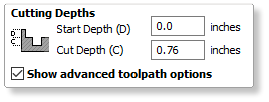
Figure 7-29. Cutting Depths menu
Edit Passes
VCarve assigns a number of passes for the end mill to cut through the material. Depending on the thickness of your material and the size of your end mill, multiple passes may be needed to achieve the desired cut depth. Pass depth is the vertical amount of material removed by each small cut; their sum total is the cut depth.
Factors like material hardness, end-mill type, edge quality, and desired cutting time determine the number of machine passes. In this case, four passes will efficiently cut through ¾″ plywood, leaving edges that require only a light sanding.
-
Click the Edit Passes… button to open the Edit Passes pop-up menu, changing the Number of Passes at the bottom of the menu to 4.
Figure 7-30. Tool Settings
Machine Vectors
To cut accurately sized holes, you’ll need to create an inside toolpath that cuts on the inside of the vectors.
-
Select Inside/Left and Conventional.
-
Use the defaults for the rest of the Machine Vectors options. Keep the “Allowance offset” at 0.0 inches and keep “Use vector start points (don’t optimize)” unchecked.
-
Ignore the Tabs section below Machine Vectors. Leave the box unchecked.
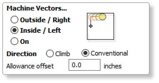
Figure 7-31. Machine Vectors menu
Name and Calculate Toolpath

Figure 7-32. Click the Calculate button to create the toolpath

Figure 7-33. It’s OK to ignore the profile toolpath warning message, because it pops up every time—but always double-check the cut depth info
-
Change the toolpath name from “Toolpath 1” to “000 Inside Holes,” a name that describes attributes of the toolpath.
-
Recheck all settings then click the Calculate button at the very bottom of the Toolpaths menu.
By default, a pop-up warning alerts you that cut depth is deeper than material thickness. Every time you create a toolpath that cuts all the way through the material, VCarve will warn you. It’s OK to ignore the profile toolpath warning message, because it pops up every time—but always double-check the cut depth info!
You may need to scroll down to see the Calculate button (see Figure 7-32).
Simulate Toolpaths
After it calculates your toolpath definition, VCarve automatically opens the 3D Window and Preview Tab, as shown in Figure 7-34. Besides allowing you to pan, zoom, and rotate the view of your sheet material, VCarve simulates your toolpath definitions through animation and visuals.
By visually showing the toolpath, or actual movements that the end-mill will make, you’ll be able to analyze the results and make any necessary corrections.

Figure 7-34. Profile toolpath created and 3D machining simulation shown
-
Zoom in and take a look around. The red lines are the X and Y, or horizontal, moves that the tool will make. The green lines are the vertical moves. The blue holes are the individual passes at different three-dimensional depths.
-
Click the tab above the visualization next to “3D View” that says “Rotational Stools” to flip back to the CAD file vector view, as shown in Figure 7-36. As demonstrated in “Creating Profile Toolpaths From Vectors”, this view shows the part vectors in red and the toolpath in pink with little arrows indicating the direction the tool will travel as it cuts.

Figure 7-35. 3D simulation of machining holes, each individual pass depth is shown in blue

Figure 7-36. Two-dimensional toolpath view, zoomed in very close; the tool makes a small, tight circle inside the red, selected vector
Seat Inside Profile Toolpaths
Next, you’ll define the Stool’s inside profiles on the seat parts. Return to the main VCarve window, to turn off the Profile Holes Layer and turn on the Profile Inside layer.
Next, you’ll create a second inside profile toolpath for the seat slots in the same way you created the fastener hole toolpaths.
Select Profile Inside Vectors
-
Close the Preview Toolpaths menu (there’s a Close button at the bottom, just like in the Drawing menu options).
-
Uncheck the 000 holes toolpath in the Toolpath List. The hole toolpaths will disappear. Unchecking a toolpath hides it from view, but it is still there and can be reselected at any time.
-
Open the Layers tab (bottom of the left Drawing menu).
-
Turn on the green inside profiles layer and hide the holes layer (shown in Figure 7-37).
-
Select all vectors on the Inside Profiles layer, Ctrl + A.
Toolpaths, once calculated, are distinct entities from the vectors used to create them. Unchecking the toolpath name from the Toolpath List will hide the toolpath, but it’s often helpful to leave it on so that you can see the relationships.

Figure 7-37. Selected seat inside profiles; the green inside profiles layer is on, and all other layers are hidden
Create Seat Inside Profile Toolpaths
-
Create a new profile toolpath by keeping the vectors selected and then clicking the profile toolpath icon under the Toolpaths menu→2D Profile Toolpath.
-
Open the Toolpath Database by hitting the Select… button under the Tool section, Toolpaths menu→2D Profile Toolpath→Tool.
-
Select a 0.25 inch end mill (¼″), Tool List→Imperial Tools→End Mill (0.25 inch).
-
Enter the settings shown in Table 7-1. Any settings not specified will be left as the VCarve Tool Database default.
Tool Diameter |
0.25 inch (¼″) end mill |
Passes |
3 |
Cut Depth |
0.76” |
Machine Vectors |
Inside/Left |
Direction |
Conventional |
Toolpath Name |
000 Inside Profiles |
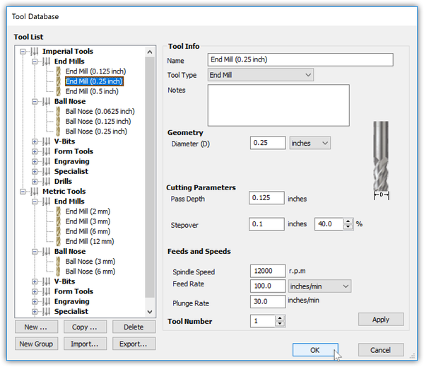
Figure 7-38. Selected 0.25-inch tool from the Tool Database
Simulate Inside Profiles
When VCarve automatically opens the 3D Window and Preview Tab, you will see this new toolpath added to the Toolpath List at the bottom of the right-hand menu.
-
Ensure that 000 Inside Profiles is turned on (checked) and review the animation and visuals of the vectors, and the actual cuts made by the ¼″ end mill.
-
Check that the material is cut all the way through, that the cut shapes match those in the original cut file, and that no details are obliterated by accidentally selecting a tool that’s too large.

Figure 7-39. Machine paths for inside cuts
Outside Profile Toolpaths
Now it’s time to cut out the parts by creating outside profiles. You’ll repeat the same process of selecting vectors and then programming the toolpaths like you did previously with the inside seat toolpaths, using the same ¼″ end mill.
Turn On Layer, Select Vectors
-
Return to the main VCarve window and turn on the Profile Outside layer, 000 AtFAB stools_profile outside.
-
Select the vectors.
Select ¼″ Tool
-
Create a new outside profile toolpath by keeping the vectors selected and then clicking the profile toolpath icon under the Toolpaths menu→2D Profile Toolpath.
-
Open the Toolpath Database by pressing the Select… button under the Tool section, Toolpaths menu→2D Profile Toolpath→Tool.
-
Select a 0.25 inch end mill (¼″), Tool List→Imperial Tools→End Mill (0.25 inch).
Create Outside Profiles
-
Enter the settings shown in Table 7-2. Any settings not specified will be left as the VCarve Tool Database default.
Tool Diameter |
0.25 inch (¼″) end mill |
Passes |
3 |
Cut Depth |
0.76” |
Machine Vectors |
Outside/Right |
Direction |
Conventional |
Toolpath Name |
000 Outside Profiles |
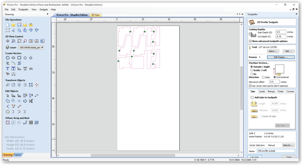
Figure 7-40. Isolate Outside Profiles
Simulate Outside Profiles
VCarve automatically adds this third toolpath (000 Outside Profiles) to the Toolpath List at the bottom of the right-hand Toolpaths menu.
As before, review the animation and visuals of the vectors, spindle path, as well as the actual cuts made by the ¼″ end mill. Ensure that kerf matches the end-mill size, that material is cut all the way through, and that the cut shapes match those in the original cut file.
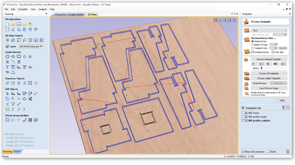
Figure 7-41. Run Simulation of Outside, Inside, and Hole toolpaths
Adding Ramps
In the previous chapter, we provided a basic conceptual overview of ramping (refer back to “Ramp Moves and Tabs” if you need a refresher). This section covers ramps from a CAM perspective and provides additional information on how to add a smooth or spiral ramp to your profile toolpaths in VCarve.
- Smooth Ramps
-
VCarve makes it easy to add smooth ramps that work well for gradually easing the tool into large parts. When creating the profile toolpath for a large part, click the Ramps tab, check “Add ramps to toolpath,” and select “Smooth.” Add a “Distance” of 6.0 inches for a large part, or add 4.0 inches for something smaller, like the Rotational Stools. The machining preview will now show cyan ramping movements.
- Spiral Ramps
-
The spiral option ramps the tool into the material slowly over the complete circumference of the profile toolpath. The angle is automatically calculated to ramp from the start point to full depth over the perimeter distance around the job.
Adding a spiral ramp to profile toolpaths for small parts, like AtFAB feet, is a good way to avoid possible part movement problems. Spiral ramps help maintain vacuum hold because they keep parts lifting.
Adding smooth ramps to pockets keeps the sides nice and clean, which helps to avoid tearout on the top face.
Add Smooth/Spiral Ramps
-
Re-open the profile toolpath you created in the last section by navigating to the Toolpath List at the bottom of the Toolpaths menu and then double-clicking on the toolpath name, 000 Outside Profiles.
-
When the 2D Profile Toolpath menu opens, scroll down to the Tabs menu and then click the Ramps tab, opening the Ramps menu, shown in Figure 7-42.
-
To add a smooth ramp, click the “Add ramps to toolpath” box, shown in Figure 7-43. The default value is 4.0″. You can keep the default.
When cutting multiple passes, the ramp moves will occur at the start z height of each pass. Ramping speed happens at the plunge rate for the tool used.
If you are cutting large parts, bump the number up to 6.0″ if you’re cutting smaller parts, dial it down.
-
Re-run the toolpath simulations you created in “Simulate Outside Profiles”. Previously there were two different toolpath line colors: red and green. The red represents travel moves, and the green lines that go straight down are vertical plunges. Now you’ll see three different colored lines; the cyan colored slanting lines are the ramp moves.
Bill Young’s AtFAB CRV files
This project does not have feet, but for the other projets in this book, it helps to add a spiral ramp (Figure 7-44) to each of the feet. To see examples of smooth and spiral ramps in VCarve pro, download Bill Young’s CRV files from designforcnc.com

Figure 7-42. The default Ramps menu, no options selected
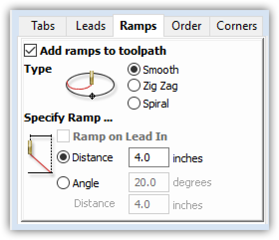
Figure 7-43. Smooth ramp added to toolpath
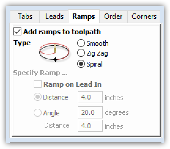
Figure 7-44. Spiral ramp added to toolpath
Toolpath Order
After programing these three toolpaths, it’s probably obvious that the CNC machine must make many multiple passes to complete a job. The CNC performs each toolpath operation separately, in a predefined cut sequence. Logically, one operation will need to go first, with the second and third to follow.
When assigning a cut sequence, it’s ideal to cut holes and interior cuts situated within larger parts first and then follow up with cutting outside profiles. Small, inside, self-contained cuts within larger parts are generally less likely to shake loose once they’re cut. Some overall parts, on the other hand, have the potential to shift or vibrate out of position, once cut from the sheet. By cutting the outside profiles last, you eliminate this risk for misalignment.
Define Cut Sequence
-
Turn all toolpaths on. Go to the Toolpath List at the bottom of the Preview Toolpaths menu and check all the boxes.
-
Use the up and down arrows to move the three toolpaths into the correct order:
-
000 Holes,
-
000 Profile Inside,
-
000 Profile Outside.
-

Figure 7-45. Toolpath cut order is important; always cut holes first, then inside profiles, and then the outside profiles—otherwise the parts may move around, causing problems
Simulation and Analysis
VCarve has many options for machining simulation and visualization that enable you to analyze and test your toolpath programming prior to fabrication.
Simulation is critical to preventing the digital fabrication equivalent of a typo, which can be a time-consuming, irreversible, costly mistake—compared to a misspelling on the page.
Visualize and Analyze
Using multiple kinds of visualization will help you catch errors made earlier in the workflow or design process, before you fabricate them. Experiment with VCarve’s various simulation and visualization features in the 3D view.
- Animated Simulation
-
-
Run the animated preview again, but now with all three toolpaths in the correct order.
-
Speed up or slow down the animation so that you can follow the cutting process.
-
- 3D Views
-
-
Zoom, pan, and rotate the view to see all parts.
-
Use Remove Waste Material to examine the cut parts on their own.
-
Turn on 2D Profiles to study cut parts relative to the original vectors.
-
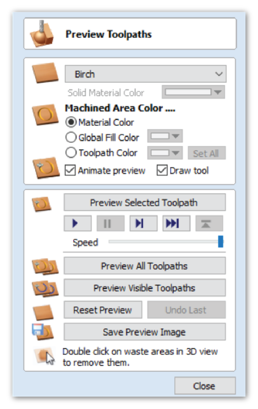
Figure 7-46. Visualization Menu
Quality Control
VCarve’s simulation features help you anticipate and plan for critical moments in the fabrication process, such as the time it takes each pass to complete, when the machine stops for manual end-mill changes, and the order of parts completion.
-
Use the simulations to check that all parts, including sniglets, are shaped properly, and that the tool cuts every part out in its entirety.
-
Is your end-mill diameter too big? Will it obliterate small details?
-
Determine whether the tool is cutting through the material and that all parts are included in the cut sequence. If you find errors, you can either adjust your design or increase your tool size and re-simulate before actually cutting.
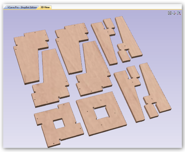
Figure 7-47. Visualization of cut parts on their own
-
Return to the Main VCarve Pro window and turn on all layers and all toolpaths so that toolpaths are overlayed onto the vectors.
-
Check the alignment and that outside and inside toolpaths are positioned correctly relative to the original vector profile, Figure 7-48.
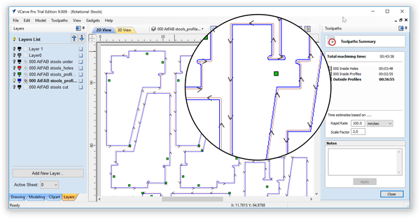
Figure 7-48. Toolpaths and vectors overlay with estimated times
Save Toolpaths for Fabrication
Toolpath Summary
-
Return to the main toolpath menu, select Toolpath Operations → Summary of All Toolpaths Including Estimated Times to get the machining specifications and times for each toolpath.
Save Toolpaths to File
-
Review these details and once satisfied, return to the main toolpath menu again to Save Toolpaths to File. Save these toolpath operations for output to Shopbot 3, or the format preferred by the CNC machine you plan to use.
If you are using the trial version of VCarve, you won’t be able to save and export toolpaths for machining, just re-save your CRV file.
Ready to Fabricate?
While this exercise ends here, your toolpath file for the Rotational Stools is ready to fabricate. Chapter 8 walks you through the exciting next steps of fabricating and assembling your first AtFAB furniture project.