
Chapter 2. End Mill to Furniture Collection
Quite a few years ago, a colleague of ours took a moonlighting job designing and building a CNC-fabricated wall of shelving for a client. He returned exhausted after a weekend of pounding his bookshelf parts together with a sledgehammer. Brute force was the only way to get the slots in his horizontal shelves to fit completely into the slots of his vertical dividers. Our friend’s frustrations stemmed from overlooking the role of the rotational cutter in subtractive machining.
Subtractive Machining
Routers and milling machines (see Chapter 6) use extremely sharp, round, spinning tools, or rotational cutters, called end mills, to make cuts in a workpiece, or the material being cut. Subtraction works like a stonecutter chiseling away material to produce a form—once the material is removed, it’s gone for good. The shavings produced during machining are called chips.
Drilling
You’ve probably used a hand drill, or are at least familiar with the concept of drilling. The most common type of drill bit, a twist drill, is designed to cut axially, with a pointed tip that plunges directly into the material. As the drill rotates a cutter around a central axis, the bit’s sharp tip bores into the material and the chips are spiraled upward through the helical flutes, or grooves, that wrap around the tool, shown in Figure 2-1.
Drills (and their bits) are tools with a singular purpose: to create holes. The side flutes on a drill bit are dull; only the tip has cutting surfaces, one on each side of its center axis.
Cutting Laterally
Like drill bits, the flutes of most end mills also have sharp bottom edges that allow them to plunge, but end mills can do many things that a drill bit cannot. In addition to plunging, end mills also have the ability to cut side to side, or laterally. That’s because the helical flutes on the sides of an end mill have teeth, or sharp cutting edges.
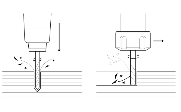
Figure 2-1. Twist drill plunging axially, end mill cutting laterally
Unlike a twist drill, the end mill’s sharp bottom edges don’t end in a single, protruding central point. When an end mill can plunge (most can), it is said to be center-cutting, or end cutting, because its flutes have sharp edges that extend around the bottom of the tool, meeting at an indented point in the center (as shown in Figure 2-1), so the end mill can cut laterally.
The Inside Corner Problem
As Figure 2-3 illustrates, a rotational cutter can never completely carve out an interior angle. The rounded corners left behind match the tool’s radius.
When cutting out parts that have both “inside” and “outside” 90-degree corners, as shown in Figure 2-2, the outside corners are cut cleanly, with their sharp right angles intact—but the inside corners are radiused—and excess material is left behind. As the end mill’s diameter increases, so does the amount of material left behind in the corners.
This is why our friend’s slotted bookcase parts didn’t fit together as intended; the excess corner material in both the horizontal and vertical slots made a flush fit impossible.

Figure 2-2. The inside corner has a sharp, 90-degree angle

Figure 2-3. A round tool cannot fill an inside corner
When a 90-degree inside angle is used to create joinery intended to slot together tightly—the leftover inside corner material prevents the cross-pieces from fitting together snugly—both the top and bottom parts stick out (Figure 2-4).
When we began to design our first CNC furniture pieces, our friend’s sledgehammer incident was fresh in our minds. We sketched different shapes that would create a flush, 90-degree fit between two parts. Illustrated in Figure 2-5, these sketches resulted in the sniglet, a corner detail design that pulls the tool deep into the inside angle, removing the radiused corner.
Figure 2-4. This crosspiece does not fit together properly—the radiused inside corner material prevents a flush fit

Figure 2-5. Using a sniglet fillet pulls the tool deep into the inside angle, resulting in flush-fitting joinery

Fillets
The sniglet is a type of fillet. A fillet is a design feature that rounds off a corner. Although fillets can be added to both outside and inside corners (and can even refer to adding material to a corner via welds), when it comes to cutting flat parts, it’s imperative to add fillets to the interior corners if you want your joinery to fit properly.
If you come from a woodworking background, you may have had to resort to extensive hand labor to remove the residual inside corner material your manual router left behind. When working with a CNC, it’s far easier, efficient, and elegant to add fillets to your files and let the machine do the work.

Figure 2-6. Machined fillet types
In addition to the sniglet introduced earlier, there are two other commonly used fillet solutions: dogbones and t-bones, shown in Figure 2-6. These fillet types are named for their appearance. When a dogbone fillet is added to both sides of a slot, the slot takes on a cartoonish, dogbone- or t-bone-like shape.
Tool Diameter Matters
Regardless of type, fillets are tool diameter dependent; their size and shape are determined by the diameter of the end mill used to cut the parts. For context, the projects in this book use both ¼″ (6mm) and 1⁄8″ (3mm) diameter tools.
Because you’re hardcoding the tool size into your design, it’s a good practice to draw fillets slightly bigger than necessary—110% larger than the actual tool diameter works well. This ensures that if the drawing needs to be scaled down slightly, the end mill will still fit onto the inside corners. Scaling is covered in detail in “Scale Your CAD File”.
Exercise: How to Draw Fillets
The best way to understand how fillets work and why they look the way they do is by drawing them yourself. Plus, it’s great practice for creating or adapting your own designs. Fire up your favorite vector graphics–capable program (something like SketchUp, Inkscape, Illustrator, VCarve Pro, or AutoCAD) and follow along.
This design exercise is software agnostic, but we recommend using SketchUp because you’ll be using for the design exercises throughout this book.
Dogbones and T-Bones
Dogbone and T-bone fillets are very similar; the core difference is where the “circle” that will accommodate the tool diameter is placed (relative to the inside corner you’re trying to eliminate).
Choose your tool diameter, or Ø. A ¼″ diameter tool is most commonly used for large, but detailed CNC projects. It’s strong enough to withstand the cutting forces and long enough to pass through ¾″ sheet materials without breaking.
Create a circle that is 110% larger than the tool’s diameter. For example, if you were using a ¼″ diameter tool, you’d draw a 0.275″ (7 mm) diameter circle with a 0.1375” (3.5 mm) radius.

Figure 2-7. How to draw a dogbone fillet

Figure 2-8. How to create a T-bone fillet
Place the circle over the inside corner. This is where dogbones and T-bones differ. The dogbone fillet rounds out the corner, while the T-bone pulls the circle out to the side of the vertex.
- Dogbone fillet
-
Intersect the circle’s radius, R, with the inside angle’s vertex and its diameter, Ø, with the part edges, as shown in Figure 2-7.
- T-bone fillet
-
Align the circle’s diameter, Ø, with the inside angle’s vertex along one side of the part, as shown in Figure 2-8.
Integrate the circle into the part lines. As shown in Figure 2-7 and Figure 2-8, draw a stroke, create a line, or use a Boolean operation to assimilate the circle into the overall part. Ensure that the lines are connected.
If you use a different size end mill, you’ll need to adjust your fillet size to match.
Sketching Sniglets
A sniglet is created using two adjacent circles. Like dogbones and T-bones, the diameter of each circle is 110% of the tool diameter. One core difference—other than the use of two circles to guide the sniglet creation lines—is that they are placed on the outside edge of the interior corner.
Draw two adjacent circles, each circle’s diameter is 110% of the tool diameter. Align the circles to the top right of the corner vertex.
Incorporate one circle into the part. The circle directly above the corner vertex will become the fillet, while the second circle is merely a guide. Using Figure 2-9 for reference, integrate the first circle into the overall part.

Figure 2-9. How to sketch a sniglet
Toolpaths
Before taking a deeper dive into joinery, we’d like to introduce a few basic CNC terms and concepts.
CNC is an abbreviation for computer-numerically controlled. A CNC machine creates physical things from digital design files. Depending on its particular capability, a CNC machine deposits, fuses, cuts, or carves materials to produce physical things. Designers develop parts or objects in a computer-aided design (CAD) software program and then export the design file into computer-aided manufacturing (CAM) software. CAM converts the design geometries into toolpaths, a combination of 3D coordinates and physical settings, that drive the physical movements of the CNC machine.
The movements of a 3D printer, robotic arm, and CNC router are all computer numerically controlled. However, the term “CNC” has become synonymous with subtractive machines. In the context of this book, CNC refers to the computer-controlled routers and milling machines that use rotational cutters.
End mills follow toolpaths, or a series of three-dimensional coordinates and codes, telling them exactly how and where to move and cut to move and cut. That may sound complicated, but it’s actually quite straightforward. Toolpaths trace the lines of a design file.
Just like a saw, the computer-controlled end mill removes material as it traces a toolpath, forming a gap called a kerf, shown in Figure 2-10. A kerf is the total width of the material removed by an end mill as it cuts, roughly equal to the diameter of the tool.
The most basic toolpath types are profile, pocket, and drill. While all three cut to user-specified depths, there are core differences.
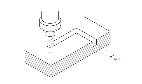
Figure 2-10. An end mill traveling along a profile toolpath creates a kerf as it cuts
Profile Toolpaths
A profile toolpath follows a line of an individual part. It’s the digital equivalent of cutting a pattern by hand. Profile toolpaths, or profiles, cut around a closed shape to a specified depth. While there is only one type of profile cut, there are three different ways to make the cut: you can choose to cut on the line, outside the line, or inside the line. No matter which side of the line you cut, this is the toolpath to use when you want to completely cut out a part.
We’ve already established that end mills have a physical diameter that removes material when cutting, creating a kerf as the material is removed. Figure 2-11 shows how the kerf is positioned for each type of profile toolpath.

Figure 2-11. Profile toolpaths can cut on, outside, or inside a line, which changes the position of the kerf and the dimensions of the part
The “on cut” view in Figure 2-11 shows the tool cutting directly on the line. This type of toolpath works well for decorative details, but is not used for machining accurately sized parts.
When the tool cuts on the line, it creates a kerf (slit) approximately equal to its diameter—but half of the kerf (equal to the radius of the tool) is positioned inside the part.
If you’re using a ¼″ tool, the total kerf is ¼″. But—because the tool is cutting on the line, you’re actually cutting into the part—removing an eighth of an inch! If your parts are designed to scale, then you need to cut outside or inside the part lines.
Outside Profile
This is the most commonly used toolpath type because it creates a true part outline. As you can see from Figure 2-11, outside profiles only remove the material outside the part line, maintaining dimensional accuracy. As end mills have a physical diameter that creates an equally large cut and kerf, cutting outside profiles feels similar to outlining a thick pattern block with a very thick marker tip.
Pocket Toolpath
A pocket toolpath cuts on the inside of a closed line or shape, removing all the material within the pocket (the recessed, cleared area) to a user-specified depth. Pocket cuts have vertical sides and a flat bottom. They’re used for anything from joinery to decorative details and many applications in between. It’s also commonly referred to as clearing a pocket and pocketing.

Figure 2-12. A pocket cut
Drill Toolpath
Drill toolpaths cause the CNC to operate like a drill press, plunging the end mill vertically into the material. Drilling creates a hole that corresponds to the diameter of the tool, which means it’s not a good choice for creating dimensionally accurate fastener holes—use inside profiles instead. Peck drilling is when the tool drills to a specified depth, then raises up to clear the chips, and then plunges again, repeating the sequence until the hole is cut.

Figure 2-13. CNC drilling
Drawing Smooth Motion
As we worked the sniglet into our first few furniture designs, we began to see our virtual CAD lines not as mere outlines of a furniture part, but as the movement of the end mill itself. This may seem like a subtle distinction, but it’s a key concept in designing for CNC. Profiles are not just shapes, they are machine toolpaths.
Figure 2-14 shows four versions of a slot with different fillet solutions: a plain corner and the dogbone, T-bone, and sniglet shapes that effectively clear the slot’s inside corners.
The sniglet’s continuous, radiused toolpath allows the CNC tool to preserve its momentum as it turns each corner, giving it an advantage over dogbone and T-bone fillets. As you can see in Figure 2-14, the dogbone and T-bone fillet toolpaths double back on themselves, causing the machine to halt at the edge of the fillet and make sharp moves to return to the part, disrupting the smooth motion and speed of the cut.

Figure 2-14. Different fillets transform the same slot
Sniglets also reduce any possible disturbance to the part during abrupt 90-degree turns of the tool, while preserving the cut speed. By smoothly incorporating corner removal into the toolpath, the simple sniglet ends up saving time and increasing efficiency, while ultimately expressing the movement of the end mill in every joinery detail.
A successful CNC design is a direct result of understanding that the lines in your CAD program are as much about the path of the mill as they are about the edge of the part. It’s not a coincidence that the expression of a tool’s role in the fabrication of a thing should also yield efficiencies for the tool itself. The sniglet became the basic element that underpinned the entire range of AtFAB furniture. The sniglet aggregates into joinery, joinery forms assemblies, and assemblies create structures, which ultimately combine to accommodate functions. It is the little that leads to much.
Eight Basic CNC Joint Conditions
An online search for “CNC joints” returns a seemingly infinite number of joinery styles. There are endless solutions for connecting wood-to-wood at every conceivable angle, each employing varying degrees of complexity. While it’s easy to get excited by the ingenuity in all these choices, it’s important to consider the relationship between the parts and the whole of a design, and the role of joinery to clarify or participate in that relationship.
Flat Parts From Sheet Materials
The projects in this book use profiles and pockets to make flat parts from sheet materials, as shown in Figure 2-15. Just as it sounds, sheet materials are manufactured materials that have been formed into flat sheets. Also known as sheet goods, stock, or stock material, they come in a wide range of materials and are produced to nominal (or standard) dimensions. Most projects in this book use ¾″ (19mm) low-cost plywood sheets that you can easily find at home improvement stores and lumber yards. For simplicity and clarity, a ShopBot PRS Alpha, capable of cutting standard 4′ × 8′ sheets of plywood, serves, as this book’s “example machine.”
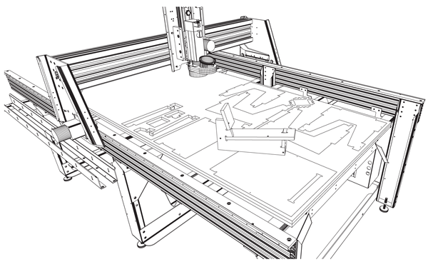
Figure 2-15. ShopBot CNC router with machined and partially assembled parts
Traditional woodworking joinery techniques evolved around a craftsperson working with hand tools in solid hardwoods with access to all sides of the workpiece. CNC joinery made with flat, plywood parts that must account for the three-axis machine, which can only cut from one side at a time.
In this section, we focus on joinery that creates large furniture objects from flat parts. Narrowing our scope allows us to categorize the majority of joints out there into eight basic joint conditions. Understanding that there are basic, elemental conditions for connecting parts to a whole will lead to better design—and provide insight into why choosing one joint detail over another is suited to a particular application in your own design.
The projects in this book utilize most of these eight basic conditions in order to get the most out of flat parts cut from sheet materials. They are summarized here to provide an overview of basic CNC joinery and construction, so that you can ultimately incorporate and evolve them in your own designs.
Overlap
Overlapping joints involve connecting two or more parts lengthwise, often to achieve a longer dimension than standard material sizes (a process traditionally known as scarfing). In its simplest iteration, the ends of each part are pocketed to overlap one another for a specific length. Adhesives or mechanical fasteners join the two parts. Woodworkers also call this connection a simple half lap, a splice lap, or half lap scarf.
A more precise fit can be achieved by using a key. A keyed overlap joint is created by pocketing a positive shape on one part, which fits into a negatively carved counterpart on the connecting part. There are many examples of hybrid overlap connections that use pocketed keys that create varying degrees of structural performance based on the shape and connection between parts.

Figure 2-16. Keyed and standard overlapping joints
Edge to Edge
Edge-to-edge connections happen at the angled intersection of two edges. Finger and dovetail joints are common examples of edge-to-edge joints. Dovetails give added structural capacity to an edge-to-edge connection by keying the fingers. Adapting dovetail joints to CNC projects involves profile cutting on one hand, and sloped contour cuts on the other.
Finger (or box) joints are well suited for CNC, as long as fillets are used to ensure a positive connection between “fingers” on each “hand.”
AtFAB designs keep the edge-to-edge connections simple by using lazy fingers that keep the number of interlocking fingers to a minimum. They provide maximum structural integrity of the finger joint while not distracting from the piece as a whole.

Figure 2-17. Dovetails, complex finger joints, and lazy fingers
Edge-to-Edge-to-Edge
These connections occur at the intersection of three edges, most commonly at the corner of a box. The principles of edge-to-edge-to-edge connections are largely the same as edge-to-edge, but the introduction of a third component (perpendicular to the corner), substantially increases the complexity. The direction and sequence of assembly factors are a consideration in these connections, as are structural integrity and aggregation into larger assemblies.
When creating this type of connection, finger joints are far simpler to work with than dovetails, which are directional. Plus, as mentioned in “Edge to Edge”, dovetail joints require more complex fabrication techniques.

Figure 2-18. Corners are formed by where the three edges meet in an edge-to-edge-to-edge connection
End-to-Face
An end-to-face connection occurs when the end of one member intersects the face of another. A through mortise and tenon joint is a traditional example of this connection. When sheet materials are used, this connection resembles a slot and tab.
For CNC slot and tab connections, the slot would typically be cut as an inside profile, while the tab would be an outside profile cut. Closely calibrating the tool diameter with the material thickness for each of these cuts will create a perfect fit.

Figure 2-19. A tab and slot formed by an end-to-face connection
End to Face to Edge
An end-to-face-to-edge connection occurs when a third part sits atop an end-to-face connection, creating a tremendously strong, integrated joint. A combination of the end-to-face and edge-to-edge, this connection could also be called a compound finger or compound slot and tab connection.
Using an end-to-face-to-edge connection requires some extra design and planning to ensure that it has a flush alignment, is structurally viable, and can be physically assembled. Close attention must be paid to the respective lengths of fingers, slots, and tabs.

Figure 2-20. An end-to-face-to-edge connection, or “compound finger”
Through
A through connection (also known as a cross-lap) aligns intersecting slots on x and y cross-pieces, so that each appears as if it’s passing through the other. The slots in each piece are ideally the same depth at the midpoint, which preserves a maximum effective load carrying area.
The real power of these connections comes when they are used serially to produce a frame or two-way structure. With larger assemblies, you will get added structural performance by placing upward-facing slots on the short-span members. This way the short-span members are effectively “carrying” the longer spanning components. When locating slots on framing members, be sure to avoid “weaving,” which would make the structure physically impossible to assemble.

Figure 2-21. These crosspieces are an example of a through connection
Three-Way
Three-way connections occur by integrating a third plane atop a through connection (or series of through connections). The tabs on the crosspieces intersect a slot in the top plane. This yields a diaphragm structure that is strong, rigid, and lightweight. Edge-to-edge-to-edge connections and end-to-face-to-edge connections are similar to three-way connections in that all are made up of composite aggregations of fingers, slots, and tabs.
In structural engineering, a diaphragm is a basic element that distributes the horizontal load across the other parts of a structure.

Figure 2-22. An exploded view of a tabletop is an example of a three way connection
Four-Way
A three-way connection becomes a four-way connection when a fourth plane is added below the through connection. This creates a torsion box where each plane is braced in all directions (see “Structures”), and loads and forces are distributed into the top and bottom planes. This produces an extremely strong and stable assembly.
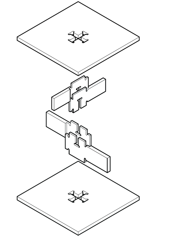
Figure 2-23. This exploded diagram of a nesting pedestal demonstrates a four-way connection
Assemblies
Joinery is beautiful on its own, but when it serves a purpose and is intelligently aggregated, joinery brings order to the larger object. AtFAB’s offerings evolved from a single piece of furniture into several distinctly different pieces, and we faced an array of questions in the design process: How should a leg meet the ground or connect with a tabletop? How should we turn a corner or terminate an edge? How should we incorporate a shelf or introduce an arm into a chair design?
There were infinite options for combining the sniglet into joinery, and we could have easily invented a new design solution to solve each discrete connection challenge that arose. This would have been a complicated process, and it ultimately would have produced a set of equally complicated, and unrelated, furniture designs. Instead, we decided to work with an overall framework that would guide our design decisions with greater consistency.
This framework began as the basic S/Z joint and then grew into several distinct joinery assemblies.
S/Z Joint
In isolation, a sniglet may seem like nothing more than a clever detail, but it underpins a complex system of furniture. Combine a sniglet and tab into a single toolpath, and you have a basic joinery element. Cutting two flat parts with this toolpath yields components that interlock to form a strong orthogonal, or right angle, connection. By multiplying, rotating, mirroring, or aggregating this basic joinery toolpath, you can combine flat parts into volumetric corners, structural frames, continuous surfaces, and more.
AtFAB uses a version of this fundamental joinery element by incorporating a sniglet and a tab, or lazy finger. When selectively combined, multiple S/Z joints form a finite number of basic joinery connections, which are in turn aggregated into larger assemblies that shape an entire line of furniture.
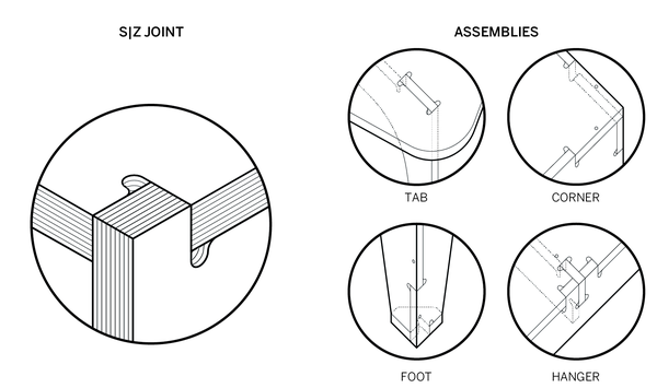
Figure 2-24. The AtFAB S/Z joint interlocks two identical tabs (left) and is the basis for the tab, corner, foot and hanger assemblies
Tab Assembly
A tab assembly locks one or more tabs into a perpendicular face, using an end-to-face joint or three-way joints to enable one-way and two-way framing. The Cat in Bag ii Table uses multiple tab assemblies to lock the tabletop into the four members underneath it. In a similar fashion, the One to Several Table uses tab assemblies that are shaped like crosshairs. Tab assemblies work on vertical surfaces, too. The sides of the Poke Credenza use tab assemblies to lock a shelf into place. The Cellular Screen uses tab assemblies to lock the front and back faces onto the vertical frame.

Figure 2-25. The tab assembly
Hanger Assembly
Hangers are beams that transfer horizontal tributary loads to vertical members. A hanger assembly is similar to a tab assembly in that it employs a three-way joint or an end-to-face-to-edge joint to lock three parts together. However, it differs because it uses these tabs to support a beam. The One to Several Table has hangers along its perimeter, where its frame (which supports the tabletop) locks in and is supported by the table’s sides. The Open Cabinet also has a hanger assembly at the bottom of each side, where a beam that carries the load of the shelves locks in and is supported by those sides.

Figure 2-26. The hanger assembly
Corner Assembly
A corner assembly brings three orthogonal faces together, forming a three-dimensional enclosure. Corners employ edge-to-edge-to-edge joints to enclose cabinetry pieces, like the top of the Poke Credenza and Open Cabinet. Corner assemblies give many AtFAB pieces a volumetric quality that transcends the idea these pieces are made of flat parts. While the One to Several Table and 90-Minute Lounge Chair and even the screen are comprised entirely of 2D parts, corner assemblies give them a three-dimensional character that suggests otherwise.

Figure 2-27. The corner assembly
Foot Assembly
A foot assembly, which is used on most AtFAB pieces, laterally secures the flat parts that form legs. When an excessive load or a lateral force is applied to a piece of furniture, the feet resist that thrust and keep the legs from splaying out. Feet also distribute the weight at the base of the leg, so the edges of the two adjacent sides don’t split over time. A foot assembly is the upside-down complement to the corner assembly, in that it uses a similar edge-to-edge-to-edge connection, and also adds to the three-dimensional quality of a furniture piece.

Figure 2-28. The foot assembly
Structures
In the same way that the elemental S/Z joint aggregates to form basic joinery, and the joinery combines to form assemblies, assemblies aggregate to create four basic structures.
The basic types of structures are: Shear, Torsion, Vierendeel, and Rotational.
When used individually or in combination in each AtFAB furniture piece, these four structures efficiently utilize flat material to resist vertical, gravity loads and sideways, lateral forces.

Shear
Diagonal distribution of loads at the corner legs. Shear structures resist lateral forces that are applied to the side of a piece of furniture and also prevent downward gravity loads from forcing legs to splay outward. The shape of the tapered legs in the 5-30 Minute Chair and the One to Several Table, among other AtFAB pieces, resist the shear forces that come from being moved around and from downward weight.

Figure 2-29. Shear
Torsion
A two-way, thin, lightweight frame with a top and bottom skin. A torsion frame allows for a long span, while the skin acts as a diaphragm that keeps the frame rigid. The One to Several Table’s tabletop utilizes a torsion structure (modified, as it has only one skin rather than two). The tabletop serves as a top skin that keeps the frame beneath square and rigid. Combined, the skin and frame afford a large expansive table that is both lightweight and stable.

Figure 2-30. Torsion
Vierendeel
An orthogonal frame with vertical, parallel members that are fixed at the top and bottom. A Vierendeel structure offers a lightweight rigid frame with rectangular space between members, which can handle a very long span. The Open Cabinet is formed by a Vierendeel frame, with shelves that are actually secondary elements. The Open Cabinet’s dividers and outer cabinet form the lightweight Vierendeel structure that can carry significant weight and handle a long span.

Figure 2-31. Vierendeel
Rotational
A frame with four rotationally configured legs and beams, which rotationally interlock at the center of the structure. The central, interlocking structure offsets the leg alignment, so legs are orthogonally arranged, but none are in plane with each other.
In a rotational structure, each of the four independently adjustable legs counterbalances the opposing leg. In Figure 2-37, this lightens the structure’s appearance and allows the legs to be easily set back from the table edge. The Cat in Bag ii Table uses a rotational structure. Several other AtFAB pieces (see Figure 2-43 and Figure 2-44) use this combination of counterbalance and centrally fixed rotational frame to form floating, cantilevered corners, which usually give furniture a lighter appearance.

Figure 2-32. Rotational
Programs
A program is a set of basic requirements, functions, or accommodations that a design must reconcile. A program gives a clear purpose to a combination of joinery, assemblies, and structures.

Figure 2-33. Program types: Sit, Work, Screen, Store
“Program” is a term drawn from architecture, where it refers to functional requirements of a building, like the quantities, sizes, and types of spaces. A program frequently includes site conditions, construction budgets, energy efficiency, detailed needs of occupants, and so on. Though seemingly less complex than an architectural program, furniture still has functional needs to address.
For AtFAB, we found that defining a program helped further organize and aggregate the structures to serve a wide range of activities. We developed four basic programs to provide adequate diversity in the collection. Beyond this chapter, you’ll learn how adaptations, ergonomic adjustments, and parametric customizations serve an array of standard programs, as well as unanticipated needs.
- Sit
-
A seating program accommodates seating of one or more individuals for a variety of durations.
- Work
-
A work program consists of a horizontal surface that accommodates working, meeting, dining, socializing, and so forth, for an individual or group.
- Screen
-
A screen program is a self-supporting vertical surface that separates two spaces.
- Store
-
This program accommodates variably sized objects within, for display or storage.
The 5-30 Minute Chair
A clear language and system of assemblies, structures, and programs provided a starting point for the design of the 5-30 Minute Chair. A chair is a deceptively difficult thing to design. There are countless considerations for what a chair is likely to encounter throughout its use (or misuse). Comfort, durability, and aesthetics all play a role.

Figure 2-34. Side elevation of the 5-30 Minute Chair
The AtFAB 5-30 Minute Chair (Figure 2-34) aims to be a durable, dignified, reasonably comfortable chair that anyone could make anywhere, with half a sheet of material and a large format CNC router. And, depending on how you choose to customize or finish your chair, it can be as utilitarian, extravagant, or eccentric as desired.
The 5-30 Minute Chair was also meant to be networked, but not in the sense that it be wired as a part of the internet of things. We saw the chair more as a thing of the internet: open hardware meant to be downloaded, hacked, transformed, and then shared with others. In this context, we saw the chair we designed as a simple organism that would evolve over generations of customization by makers who were downloading it. In this open context, we see a designer’s role as offering up an elemental, well-functioning object, which is embedded with an invitation for others to make it their own, and then to keep sharing.
But before any of this was possible, there were some very basic and fundamental design challenges presented by the chair. How could flat sheet material components comfort the human body in the same way that contoured or upholstered chairs do? How would flat parts angled for posture be joined to adjacent parts? How does the chair handle the intensive lateral forces caused by sitting down and standing up? What is the thinnest profile that will still preserve structural integrity? How are successful outcomes and “quality control” ensured, when the chair is downloaded and made half a world away? How does a designer propose something that invites others to evolve it?
We knew the chair couldn’t be made comfortable by adding upholstery or by molding or contouring parts, so we tried to understand how comfortable it could be with the flat materials and CNC profile toolpaths we were using. An important rule for a designer is to be honest with the materials and tools at hand, to understand what’s possible, and to work with it directly. We estimate that this chair will remain comfortable for 5 to 30 minutes of sitting. Since some portion of comfort is related to balance and distribution of weight in a sitting body, its proportions are drawn from basic ergonomic rules, which determine the optimal angle for the chair’s seat and back. The chair poses the sitter’s center of gravity at the center of its structure. This leads most people who sit in it to remark that it is more comfortable than it looks!
Structurally, the chair’s interlocking joints distribute loads and forces from the seat and seatback into the sides, and from the four legs into the feet. (see “Structures”) While the 5-30 Minute Chair uses fasteners as secondary elements that hold individual parts together, the slots and tabs do all of the serious structural work, distributing the loads and forces into adjacent pieces.

Figure 2-35. The slot in the seat is slightly wider than the thickness of the material, in order to accommodate the angled intersection with the tab.
Some of the most recognizable attributes of the chair emerged from unique functional and structural challenges. For instance, our system of assemblies, structures, and programs did not offer an obvious solution for introducing a sloped seat and back into a fabrication system optimized for flat, orthogonally1 arranged parts. We resolved the challenge by altogether avoiding the intersection of these two non-orthogonal parts and leaving a gap between the seat and the seat back. For us, sometimes selectively avoiding an issue like this can be a design strategy in and of itself. We fixed the seat in place laterally with a tab that slots through its front edge (Figure 2-35), and secured the seat vertically with three-sided slots in each side part to hold the back corners of the seat. The seat back, the back legs, and back edge of the seat serve as spacers to keep the chair sides apart. The stoutly tapered legs, formed by the sides, front, and back parts resist the diagonal shear forces that come from the everyday use of a chair.
As we designed the chair, we looked to the system to help us solve design problems. When the system didn’t offer an obvious solution to unique conditions, we’d let our interests guide us. Balancing the systemic and the specific is an example of what designers confront throughout the design process. At such moments, our interests were purely functional, while at other times, they were compositional or even whimsical. The important thing is to tap into whatever drives your curiosity and incites you to want to make things.
Iteration and Design Frameworks
This system of joinery, assemblies, structures, and programs, around which AtFAB is organized, is an example of a design framework. Frameworks can take many forms and are helpful tools in making decisions when designing furniture or almost anything else.
Inventing a framework doesn’t have to be a rigid, linear, or top-down process. Designing a second or third furniture piece often provoked us to rethink an elemental detail or assembly used in an earlier piece. Such rethinking is an opportunity to refine (or altogether reconsider) how a particular assembly can work in multiple instances instead of just one. For example, the AtFAB foot assembly originated for the 5-30 Minute Chair but evolved as it was incorporated into several subsequent furniture pieces. The hanger assembly was designed by working back and forth between several pieces that required structural beams. Similarly, the corner assembly and rotational structure emerged as we simultaneously designed several pieces that shared common requirements. This cycle of testing, rethinking, and improving is an example of iteration, and is an essential part of the design process. As we iterated upon our framework through the process of designing ever more pieces, AtFAB coalesced into a coherent collection with its now recognizable details and volumetric form.
Your own design framework might consist of common details, proportions, fabrication techniques, or anything that makes sense to your project or preoccupations. However it’s organized, you will find frameworks especially useful in streamlining the decision-making process. When your design task grows in scale or complexity, you will inevitably face numerous decisions about connecting parts and joinery. Rather than inventing a new detail or assembly to solve every new problem, a clear, useful framework will guide you toward consistent solutions. In aggregate, these solutions are what will help you achieve a coherence in anything you design.
Evolution From the Chair to AtFAB
The 5-30 Minute Chair was followed by other designs, with each new piece initiating the iterative refinement for AtFAB’s overall language and system of joinery, assemblies, and structures. Through this process, AtFAB became both a furniture collection and a library of CNC details and techniques.
Rotational Stools
The Rotational Stools in Chapter 8 are the smallest, simplest furniture objects in the collection and in this book. Each version of the stool has two part types: a seat part and leg part. Four identical legs are organized into a rotational structure, which interlocks into the seat. The stools have a substantial amount of joinery while using a relatively modest amount of material, which makes them ideal for this book’s first project and introducing basic CNC workflow.
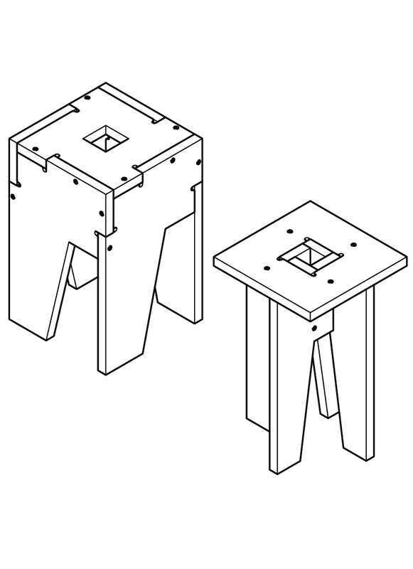
Figure 2-36. Rotational Stools
Cat in Bag ii Table
Like the Rotational Stools, the Cat in Bag ii Table in Chapter 9 is a rotational structure with four similar leg parts that lock into the table top with three-way joints. As a project, this larger furniture piece introduces new workflow steps, as well as basic concepts of digital technique. The project also provides ample opportunity to experiment with materials and finishes.

Figure 2-37. Cat In Bag ii Table
90-Minute Lounge Chair
The 90-Minute Lounge Chair in Chapter 11 embodies all of the challenges presented by the 5-30 Minute Chair, with greater intensity. The Lounge Chair requires the intersection of multiple sloping parts and introduces parts that govern relationships between other parts. The chair’s “arm” piece connects and poses virtually all of the other components of the chair into their final positions. The Lounge Chair project also introduces how to use a jig to streamline assembly. This project also involves pocket cutting into the sides of the chair and machining four keys that fit into the pockets.

Figure 2-38. 90-Minute Lounge Chair
One to Several Table
The One to Several Table in Chapter 13 is formed by a partial torsion box structure that is deep enough to hold computers and monitors, and shallow enough to work ergonomically with the myriad of task chairs. The table introduces joinery that connects three surfaces, both in the middle of the table and along its edges. This table file is accompanied by an optional parametric customization app, which enables you to transform its overall dimensions, fine-tune material thickness and sniglet size. A link to the Processing files and instructions on how to install and use them can be found in Chapter 12.

Figure 2-39. One to Several Table
Open Storage Cabinet
The Open Storage Cabinet in Chapter 14 combines all techniques presented in earlier chapters. From pocket cuts to managing multiple sheets to integrating multiple material thicknesses to working with an expanded parametric app, the Open Storage Cabinet offers a chance to put nearly every concept together in one project.

Figure 2-40. Open Storage Cabinet
Poke Credenza
The Poke Credenza in Chapter 15 is a volumetric storage cabinet with a modest span and a set of sliding doors that move smoothly without hardware. It was AtFAB’s first entirely CNC-fabricated piece with moving parts. The doors are made of a thinner sheet material, which provides the challenge of coordinating fabrication details and offers an opportunity to explore CNC patterns.

Figure 2-41. Poke Credenza
Cellular Screen
The Cellular Screen in Chapter 16 is a partition that demonstrates how using multiple interlocking assemblies can overcome the size limitations of standard plywood and CNC dimensions. It’s a short step from this partition to small structures. The screen’s parts aggregate to form a lightweight structure that can handle a long span and vertical rigidity. Fabricating the Cellular Screen is straightforward. It has simple toolpaths, parts, and assemblies like the projects that precede it. The screen introduces the concept of working on a large project, and the necessary planning and managing of a project with many parts.

Figure 2-42. Cellular Screen
AtFAB Furniture Collection
Figure 2-43. The entire AtFAB furniture collection, Part I
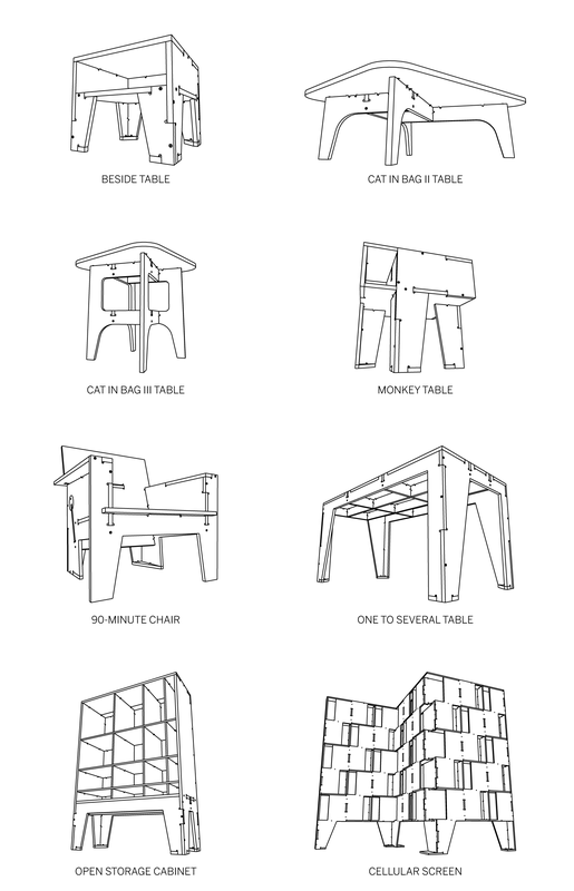
Figure 2-44. The entire AtFAB furniture collection, Part II
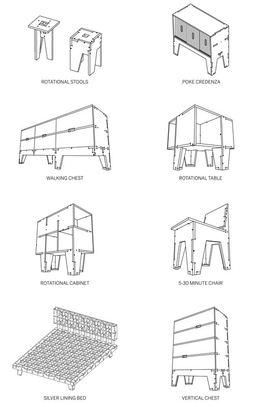
Figure 2-45. CNC tool making a down cut

1 Orthogonal, at right angles.