
CHAPTER 20 Connectivity and networks
Despite all that has been covered in the past 19 chapters, there are still important areas in embedded systems which have been little mentioned. One area is so important that this chapter is dedicated to it.
If you implemented the hand controller board on the Derbot AGV, and maybe another I2C device, then you created a little network. This approach is being replicated in every sort of situation, where different systems or subsystems are communicating with each other. In the home, workplace, motor vehicle, factory and across the world, thinking things are organising themselves into networks. Their means of communication are becoming increasingly diverse: not just electrical, but also optical fibre, infrared or radio.
This chapter deals with issues of connectivity and networking – the medium of connection used to create data links and the means by which data is actually formatted, moved and interpreted over those links. Essentially, the chapter is a survey of certain communication techniques and technologies. Like the diverse life-forms which inhabit the earth, we will find that network mechanisms are incredibly varied, each adapting itself to the needs of its very particular environment.
In this chapter, you will learn about:
As each topic is a major field in itself, the chapter does not aim to provide complete solutions. It just gives overviews and ideas for further exploration. There are no design examples.
20.1 The main idea – networking and connectivity
There are many situations in which we need to provide connection between different systems or subsystems. In the domestic environment, the automated household is in the process of becoming a reality. Here different household appliances and gadgets may all be connected together, for example through the Internet. Elsewhere, there are other needs for networking. The modern motor vehicle may contain dozens of embedded systems, all engaged in very specific activity, but all interconnected. In the home or car situation, connections may be long-term and stable. However, other networks or connections are transitory, for example when data is downloaded from a personal organiser to a laptop over a wireless link. All of these are of interest to the embedded designer and they pose very diverse challenges.
The traditional means of providing network connectivity has been through cabling, allowing electrical signals to flow from one subsystem to another. The computer I am currently writing at, no longer one of the newest, is festooned with cables, linking mouse, printer, scanner, Internet connection, speakers and all my PIC development tools! This need not be the only way. It is, of course, possible to make a data connection without any physical link. The most common alternatives to a cable connection are light or radio. There are many variations on each. We have long had TV remote controls, communicating by infrared. We have also had radio communication for many years; this has been adapted most effectively for data links within the computer environment.
Providing a network is about much more than just providing connectivity, important though this is. In a complex system it is also essential to deal in depth with how data is formatted and interpreted, how addressing is achieved, and how error correction can be implemented. All of this is pretty much independent of the physical interconnection itself. In order for different nodes to communicate on a network, there must therefore be very clear rules about how they create and interpret messages. We have already seen aspects of this with definitions of standards like I2C. This set of rules is called a ‘protocol’, taking the word from its diplomatic and legal origins. Let us explore the concept of the protocol.
20.1.1 A word on protocols
With large networked systems, protocols can become incredibly complex, defining every aspect of the communication link. Some of these aspects are obvious and others less so. To aid in the complex process of defining a protocol, the International Organisation for Standardisation (ISO) devised a ‘protocol for protocols’, called the ‘Open Systems Interconnect’ (OSI) model. This is shown in Figure 20.1. The OSI model sweeps up from the mundane and physical (defining what type of connectors we use or what voltages are recognised), to the more abstract (defining, for example, how data is encrypted and how error correction can be achieved).

Each layer of the OSI model provides a defined set of services to the layer above, and each therefore depends on the services of the layer below. The lowest three layers depend on the network itself and are sometimes called the ‘media layers’. The physical layer defines the physical and electrical link, specifying, for example, what sort of connector is used and how the data is represented electrically. The link layer is meant to provide reliable data flow, and includes activities such as error checking and correcting. The network layer places the data within the context of the network and includes activities such as node addressing.
The upper layers of the OSI model are all implemented in software. This takes place on the host computer, and the layers are sometimes called the ‘host layers’. The software implementation is often called a ‘protocol stack’. For a given protocol and hardware environment, it can be supplied as a standard software package. A designer adopting a protocol stack may need to interface with it at the bottom end, providing physical interconnection, and at the top end, providing a software interface with the application.
This model forms a framework against which new protocols can be defined and a useful point of reference when studying the various protocols already available. Further information on the ISO OSI model may be found in Ref. 20.1. In practice, any one protocol is unlikely to prescribe for every layer of the OSI model, or it may only follow it in an approximate way.
A number of network protocols and means of connection are outlined in the sections that follow. To implement any of these, a physical and a software system will, of course, be required. We will look at a number of options for these, focusing on available hardware subsystems and available software drivers.
20.2 Infrared connectivity
Infrared (IR) data communication has been with us for many years, becoming widely seen first in applications like TV remote controls. Infrared signals are easy to generate and detect, using low-cost semiconductor devices. Being out of the visible spectrum, it is comparatively easy to apply optical filters which exclude visible light, and hence to avoid interference.
The characteristics of all IR links are that data is communicated by a modulated beam of light. The link must therefore be line of sight. It is generally short range and communication is on a one-to-one basis. In this simple characterisation lie a number of interesting advantages and disadvantages. Because it is directional and local, the risk of interference is little and security is good. Because it must be line of sight, however, the ability to engage in wider networks is restricted. Infrared communication can be very low cost and enjoys the advantage of not being regulated by law.
While the early applications were mainly in control, like the TV remote, it was equally evident that IR was good for data communication. This has become a huge growth area for the technology, particularly in situations where a single cable can be replaced, for example in transfers of data from a hand-held device (like a personal organiser or digital camera) to a computer, or between computer and printer.
The Infrared Data Association (IrDA) [Ref. 20.2] is a group of manufacturers who have defined a series of standards for IR links, ranging from simple control to intensive data transfer.
20.2.1 The Infrared Data Association and the PIC microcontroller
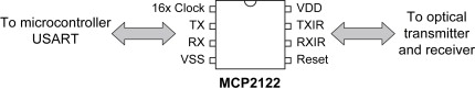
Infrared communication is a natural area of activity for the small embedded system. Microchip offers several IR encoder/decoder ICs. An example is the MCP2122 [Ref. 20.3], whose pin connections are shown in Figure 20.2. This is intended to interface between a microcontroller on one side, and an infrared source and receiver on the other. Thus, the TXIR pin can directly drive an IR LED, while the RXIR can connect to a sensor. Four interconnections are required with the host microcontroller: TX, RX, Reset and 16x Clock. The TX and RX lines connect to the USART of the host microcontroller, just as described in Section 10.10 of Chapter 10. A clock source, running at 16 times the intended baud rate, is also required. This is connected to the 16x Clock line. It can be generated through the microcontroller CCP module, as described in Ref. 20.4. A Reset input allows the host microcontroller to return the IC to its reset condition.
The previous paragraph demonstrates that the physical connection of an infrared port to a PIC microcontroller is simple, and from this stage informal links can be explored between two such nodes. The usual application is to implement data communication under an IrDA standard. The detail of this is beyond the scope of this book, but can be found in a number of Microchip application notes, for example Ref. 20.5.
20.3 Radio connectivity
While IR communication has some clear advantages, its need for line-of-sight communication is in many cases a significant disadvantage. Therefore, radio links are of very great interest. A low-power radio system can have local connectivity and can communicate through walls or other (non-conductive) obstructions. Yet now it is not line of sight, there is a major risk of interference between networks trying to occupy the same space. Imagine a place, say a hotel lobby, full of people with radio-enabled data communication devices. How do we avoid the risk of massive interference between them all? This section surveys a couple of approaches used.
20.3.1 Bluetooth
A major player in the field of radio data communication is Bluetooth, which faces the challenges of data communication by radio in an interesting way. The development of Bluetooth is controlled by a group of electronics manufacturers, the Bluetooth Special Interest Group [Ref. 20.6]. It operates between 2.402 and 2.480 GHz, a band originally reserved by international agreement for industrial, scientific and medical (ISM) applications, but now also widely used for local wireless data networks.
Bluetooth provides data links between such devices as cell phones, computers, digital cameras and headphones. It has these characteristics:
• A low-power radio link – power is around 1mW whereas that of a mobile phone is 3 W.
• A data rate originally of 1 Mbps and currently (Bluetooth 2.0) of 3 Mbps.
• Spread-spectrum frequency hopping is applied, with the transmitter changing frequency in a pseudo-random manner 1600 times per second.
When Bluetooth devices detect one another, they determine automatically whether they need to interact with each other, for example through data exchange. This is without any user interaction. Each device has an address, and it is by the address that it determines whether another device that it has detected is of interest to it. Bluetooth systems in contact with each other in this way then form a piconet. Once communication is established, members of the piconet synchronise their frequency hopping, so they remain in contact. A single room could contain several piconets, each containing devices which relate to each other. Each piconet is switching together. For the occasions of momentary clash, there is software that can detect and reject the corrupted data.
There is considerable cleverness in Bluetooth, in the way it can autonomously configure a network and maintain high data rates. This does, however, make it costly and complex for the small or simple system. Therefore, we turn to look at an alternative, Zigbee. This carries some of the Bluetooth attributes, but is far simpler.
20.3.2 Zigbee
Zigbee is a recent standard, managed by members of the Zigbee Alliance [Ref. 20.7]. It gains its inspiration from Bluetooth, but aims to be simpler and cheaper, with a smaller software overhead requirement. It applies the IEEE 802.15.4 Low-Rate Wireless Personal Area Network standard. Like Bluetooth it operates in the ISM bands of the radio spectrum.
Zigbee is particularly appropriate for home automation, and other measurement and control systems, with the ability to use small, cheap microcontrollers. Data rates are low and power consumption minimal.
There are two Zigbee device types, the Full Function Device (FFD) and the Reduced Function Device (RFD). An FFD can pass data from other devices, so can take on a routing role. Each network must have a coordinator, and only an FFD can take on this role. An RFD has minimal memory and functionality, and can communicate with an FFD but not pass data on. The minimal power requirement of a Zigbee network is possible because an RFD node can spend most of its time in Sleep mode. They wakes up briefly, just to confirm they are still part of the network.
20.3.3 Zigbee and the PIC microcontroller
Zigbee is an interesting standard to engage with, and a natural one to apply with PIC microcontrollers. A possible physical implementation of a Zigbee node is illustrated in Figure 20.3.

The link is through a single-chip radio transceiver, such as the Chipcon (now acquired by Texas Instruments) CC2420 [Ref. 20.8]. A microcontroller interfaces to this through an SPI link and certain control lines. Microchip has produced extensive firmware which can be adapted to apply the protocol. An example, described in Ref. 20.9, allows a Zigbee Coordinator or RFD to be implemented. Figure 20.4 shows a Derbot implementation of the Zigbee protocol, making use of a Microchip demo card.

20.4 Controller Area Network and Local Interconnect Network
We met in Chapter 10 the three main ‘work horses’ of serial communication in the embedded environment – SPI, I2C and asynchronous. While these are good standards, they each have their own limitations. In particular, none is fault-tolerant. This section looks at two serial standards which are developed for very specific applications, where high reliability is a key requirement.
20.4.1 The Controller Area Network
The concept of the Controller Area Network (CAN) was developed as the demand was growing for data communication in the motor vehicle environment. With its high level of electromagnetic interference and wide temperature and humidity range, this is a hostile environment for any signal and indeed for any electronic device. Moreover, very high reliability is essential. The serial standards developed for the benign environment of home or office were completely inappropriate and a new standard was therefore needed. Initially, CAN was developed by the German company Bosch. They published Version 2.0 of the standard in 1991, and in 1993 it was adopted by the ISO as an international standard, ISO 11898. At the time of writing, CAN specification Version 2.0B can be downloaded from the Bosch website [Ref. 20.10].
The CAN standard addresses only the lower two levels of the ISO/OSI model of Figure 20.1, but takes some fairly revolutionary approaches in so doing. With its very high level of data security, it is inevitably complex and just the briefest overview is given here. The main features are listed below:
• Communication is asynchronous, half duplex, with (for a given system) a fixed bit rate. The maximum for this is 1 Mbit/s.
• The configuration is ‘peer to peer’, i.e. all nodes are viewed as equals. There is, however, a mechanism for prioritisation. Master and slave designation is not used.
• Logic values on the bus are defined as ‘dominant’ or ‘recessive’, where dominant overrides recessive. Physical interconnect is not otherwise defined.
• The bus access is flexible. With all nodes being peers, any can start a message. An ingenious arbitration process is applied in the case of simultaneous access, which does not lead to loss of time or data. The arbitration process recognises prioritisation.
• Bus nodes do not have addresses, but apply ‘message filtering’ to determine whether data on the bus is relevant to them.
• Data is transferred in frames, which have a complex format. This starts with identifier bits, during which arbitration can take place. Eight data bytes are allowed per frame.
• There is an exceptionally high level of data security, with exhaustive error checking. A node that recognises that it is faulty can disconnect itself from the bus.
CAN is now very widely applied in the motor vehicle environment. Figure 20.5 shows the block diagram of just part of a hypothetical car network. Each of the blocks represents a small embedded system – the radio, door, seat and so on. One of these, the door, we met right at the very beginning of the book, in Figure 1.2. All subsystems are networked together by the CAN bus. Another network, not shown, also connects to the Central Control module. It controls the vehicle locomotion – for example, engine, brakes and transmission

20.4.2 Controller Area Network and the PIC microcontroller
Just as we have seen PIC microcontrollers with I2C or SPI ports, so there are others with on-chip CAN modules. The current version of the Microchip CAN module is called the ECAN – the Enhanced CAN module, which distinguishes it from earlier Microchip CAN modules. An example is the PIC 18F2480. Its data sheet [Ref. 20.11] contains details of the ECAN module.
The ECAN module is complex, containing features to buffer data, to format it in the required way and to check for errors. It has numerous control registers. It would be extremely time-consuming to write code for it from scratch. Therefore, Microchip supplies a set of C routines, described in Ref. 20.12, which can immediately be used to build up a program.
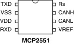
Whichever microcontroller is used, it must still be interfaced to the physical bus, meeting the electrical needs of the connection. This is usually done with a special interface IC, of which the Microchip MCP2551 is an example. Its pin connection diagram is shown in Figure 20.6 and data in Ref. 20.13. The CAN bus implementation used is differential, and connects to the CANH and CANL pins. An external resistor connected at Rs controls the slew rate of the data signal, with a slower rate minimising electromagnetic interference. The microcontroller connects from its ECAN module to the RXD and TXD pins.
20.4.3 The Local Interconnect Network
While CAN has proved itself as the provider of very high-reliability data communication, it is also complex and costly. Not all links in the motor vehicle environment actually require the full capability of CAN. Therefore, the Local Interconnect Network (LIN) was developed to work alongside CAN. The standard, first released in 1999, is managed by the LIN consortium [Ref. 20.14].
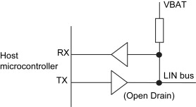
The LIN bus is intended to be small and slow, communicating mainly with intelligent sensors and actuators. The network topology is fixed. There is a single master and all other nodes are slaves. The master consequently has greater processing power. The slaves need only have very limited processing power or can just be dedicated hardware. This makes them potentially very low-cost. An interesting way that cost is minimised is that slaves can use simple RC oscillators, continuously resynchronising themselves as data is exchanged. The maximum data rate is a very modest 20 Kbit/s. The master initiates all data transfers and only one slave may respond. There is no mechanism to cope with multiple access to the bus. The data link is single wire, with the concept shown in Figure 20.7. Like the CAN bus, logic states are recessive (logic high) and dominant (logic low).
A LIN data frame consists of ‘header’ and ‘response’. The header is always from the master and data response from a single slave. The speed can be chosen from 1 to 20 Kbit/s. The header consists of:
• A ‘Break’ field, which alerts the slaves to an incoming message.
• A ‘Sync’ byte at the intended data rate, containing the value 55H, against which slaves calibrate their own clock period.
• an ‘Identifier’, which identifies a slave or slaves and specifies an action to be undertaken.
The response is a message of up to eight bytes, placed on the bus by just one slave. This is followed by a ‘Checksum’. In earlier versions of the bus only data bytes were checked; in the most recent the Identifier value is included in the checking process.
There are two bus states, ‘Sleep’ and ‘Active’. Nodes enter Sleep after a time-out period and can be reactivated by the ‘Wakeup’ frame.
Interestingly, the LIN standard also includes software elements. The LIN API (Application Programmers Interface) provides a set of standard C function calls, which between them implement all LIN functionality. This makes it easy to develop the software and then to test it.
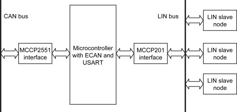
In many environments, a LIN bus system may be designed to interface with a CAN bus system. A possible LIN/CAN system is shown in Figure 20.8. Central to this is a microcontroller, such as the 18F2480, which has both CAN and USART capability. The microcontroller shown acts both as the LIN master for the LIN network and as a peer node on the CAN bus.
20.4.4 The Local Interconnect Network and the PIC microcontroller
To implement a LIN master or slave in hardware, all that is needed is a microcontroller with USART capability and a bus interface IC. An example is the Microchip MCP201, shown in Figure 20.9. This implements the buffering seen in Figure 20.7. Connection is made between the host microcontroller's USART and the RXD and TXD pins of the MCP201. Power is supplied to the ’201 via the VBAT pin. There is an internal voltage regulator on board and the interface chip is able to supply power from its VREG pin to the host microcontroller. The ![]() pin is used both to flag a fault, in which case it acts as output, and to set the data slope. The LIN line connects to the LIN bus. Full data on this device can be found in Ref. 20.15.
pin is used both to flag a fault, in which case it acts as output, and to set the data slope. The LIN line connects to the LIN bus. Full data on this device can be found in Ref. 20.15.

As with most other standards discussed, Microchip has published example firmware as a starting point for developing code. Reference 20.16 provides code for both master and slave, in the 2.0 version of the bus.
20.5 The Universal Serial Bus
In ‘the old days' of personal computers we had a complex assortment of parallel and serial data links to hook up printer, mouse, keyboard and so on. USB was originally introduced to provide a more flexible interconnection system, whereby items could be added or removed without the need for reconfiguration of the whole system. USB is now ubiquitous and very familiar, widely used for its original purpose but also to connect all manner of devices, for example digital cameras, MP3 players, webcams and memory sticks, to the PC.
USB is managed by the USB Implementers Forum, whose web site is given as Ref. 20.17. USB specifications can be downloaded from this site. They are formidable documents, but parts of them make interesting reading. The specification for Version 2.0 is given in Ref. 20.18. While there is the more recent Version 3.0 (2008), current Microchip implementations remain with Version 2.0.
A USB network has one host, and can have one or many ‘functions’, i.e. USB-compatible devices which can interact with the host. It is also possible to include hubs, which can have a number of functions connected to them and which in turn link back to the host. Three data rates are recognised, high-speed at 480 Mb/s, full-speed at 12 Mb/s and low speed at 1.5 Mb/s. The last of these is for very limited-capability devices, where only a small amount of data will be transferred.
USB uses a four-wire interconnection. Two, labelled D+ and D−, carry the differential signal and two are for power and earth. Within certain limits USB devices can draw power from the bus, taking up to 100 mA at a nominal 5 V. A higher power demand can also be requested. This is supplied by the host. Alternatively they can be self-powered.
When a device is first attached to the bus the host resets it, assigns it an address and interrogates it (a process known as enumeration). It thus identifies it and gathers basic operating information, for example device type, power consumption and data rate. All subsequent data transfers are initiated only by the host. It first sends a data packet which specifies the type and direction of data transfer and the address of the target device. The addressed device responds as appropriate. Generally there is then a handshake packet, to indicate success (or otherwise) of the transfer.
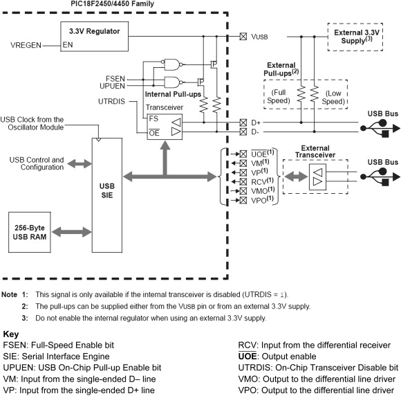
20.5.1 Using PIC microcontrollers with USB
A number of PIC microcontrollers have USB ports as peripherals. An example is the 18F2450, whose USB peripheral is shown in Figure 20.10. This versatile little port can link to a host, offering full- and low-speed connection. Some of the key control signals, establishing different operating conditions, appear in the diagram. An internal transceiver can be used for simple applications. However, connections to an external transceiver are available, for example if electrical isolation from the microcontroller is required. Similarly, an internal voltage regulator can be enabled to power the bus. Internal and external pull-up resistors are connected as needed, to meet the different operating requirements.
20.5.2 USB On-the-Go
The whole concept of USB depends on a host device, normally a PC, with other devices connected to it at will. However, as its popularity and technology developed, the need arose to connect portable devices directly, to each other, without the need for a host. This is the basis for USB On-the-Go, which is defined as a supplement to USB 2.0. The On-the-Go standard allows the addition of limited host capability to devices which have traditionally been peripheral only. Devices can act as either host or peripheral, or switch between roles. The standard also makes special consideration for low-power requirements. All of these are of course of particular interest in the embedded world.
20.6 Embedded systems and the Internet
Needless to say, the Internet has transformed communication worldwide over the past decade. The interest of this book is very much with the small embedded system, and the internet is viewed commonly as being something linked to the latest of desktop computers. Do the two have anything in common? The answer, maybe surprisingly, is yes! It is possible to link the small embedded system to the Internet and thence to network devices which are under embedded control. Once the link is there, it can be used for many things: to monitor status or exert control, or even to cause program or data downloads. Examples include the washing machine that can alert the repair man to an impending fault, the vending machine that can tell the Head Office it is empty, the manufacturer who can download a new version of firmware to an installed burglar alarm, or the home owner who can switch on the oven from the office or check that the garage door is closed.
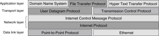
Internet communication makes use of a suite of protocols, usually called collectively after the two most important: TCP/IP (Transmission Control Protocol/Internet Protocol). An example Internet protocol stack is shown in Figure 20.11. The relationship of this to the ISO/OSI model is also shown.
20.6.1 Connecting to the Internet with the PIC microcontroller
The Internet is the most complex of the protocols reviewed in this chapter. Microchip, however, provides good support, in terms of Application Notes, demonstration hardware (the PICDEM.net board) and, importantly, a modular TCP/IP stack. This is implemented in C with a version available for 18 Series microcontrollers. It can be downloaded from the Microchip website and is described in Ref. 20.20. The great benefit of this is that the user does not need to get involved in the fine detail of the protocol. The stack forms a set of utilities that service the needs of the TCP/IP protocol, forming an equivalent to Figure 20.11. It is responsive to both the user's program and to events on the external connection. The stack occupies around 20 Kbytes of code.
To gain familiarity with networking PIC microcontrollers to the Internet, use of the PICDEM.net board and/or its accompanying documentation is recommended.
Summary
• Modern systems place very great demands on the need to communicate and network. The characteristic of the chosen network will be driven by the application. Considerations of flexibility, reliability, ease of use, data speed, power consumption and cost are all very important.
• Embedded systems often, but not exclusively, have an interest in low-speed, low-data-volume systems. High reliability is essential in a number of situations.
• Interconnection traditionally is electrical. Other techniques are possible and frequently advantageous. These include infrared and radio.
• In some situations embedded systems need to access small and local networks, and in other cases major networks, including the Internet.
• Small networks may be dedicated and fixed, like a LIN system, or they may be flexible and possibly transitory, like a Bluetooth or Zigbee system.
• Very high reliability, accompanied by some complexity, is available in the CAN network.
• Microchip supply valuable support to implement a range of networks and interconnections, in the form of microcontrollers with dedicated communication modules, recommended circuits and free published firmware.
20.1. Freeman R.L. Practical Data Communication 2nd edn 2001 Wiley ISBN 978-0-471-39273-6
20.2. Infrared Data Association (IrDA) website: http://www.irda.org/
20.3. MCP2122 Infrared Encoder/Decoder Data Sheet (2004). Microchip Technology Inc., Document no. DS21894B.
20.4. Interfacing the MCP2122 to the Host Controller (2004). Microchip Technology Inc., Application Note AN946, Document no. DS00946A.
20.5. Programming the Pocket PC OS for Embedded IR Applications (2004). Microchip Technology Inc., Document no. DS00926A.
20.6. The official Bluetooth website: http://www.bluetooth.com/
20.7. The Zigbee Alliance website: http://www.zigbee.org/
20.8. CC2420 2.4 GHz IEEE 802.15.4/ZigBee-ready RF Transceiver Data Sheet (2007). Texas Instruments, Document no. SWRS041B; http://www.ti.com/
20.9. Microchip ZigBee-2006 Residential Stack Protocol (2008). Microchip Technology Inc., Application Note AN1232, Document no. DS01232A.
20.10. The CAN section of the Bosch website: www.can.bosch.com/
20.11. PIC18F2480/2580/4480/4580 Data Sheet (2003). Microchip Technology Inc., Document no. DS21667D.
20.12. PIC18C ECAN ‘C’ Routines (2003). Microchip Technology Inc., Application Note AN878, Document no. DS00878A.
20.13. MCP2551 High-Speed CAN Transceiver Data Sheet (2003). Microchip Technology Inc., Document no. DS21667D.
20.14. The LIN Consortium website: http://www.lin-subbus.org/
20.15. MCP201 LIN Transceiver with Voltage Regulator (2003). Microchip Technology Inc., Document no. DS21730E.
20.16. LIN 2.0 Compliant Driver Using the PIC18XXXX Family Microcontrollers (2003). Microchip Technology Inc., AN1009, Document no. DS01009A.
20.17. The USB Implementers Forum website: http://www.usb.org/
20.18. Universal Serial Bus Specification. Revision 2.0 (April, 2000). Compaq, Hewlett-Packard, Intel, Lucent, Microsoft, NEC, Philips.
20.19. PIC18F2450/4450 Data Sheet (2008). Microchip Technology Inc., Document no. DS39760D.
20.20. The Microchip TCP/IP Stack (2008). Microchip Technology Inc., AN833, Document no. DS00833C.