Chapter 4: API Creation
A software platform's success is often defined by the ease with which engineers can build solutions using that platform. What can lead to an elongated Software Development Life Cycle (SDLC) and is a genuine gripe among experienced engineers (such as yourself, of course!) is if the software of their choice does not allow for compartmentalized development and testing.
Apart from support for a compartmentalized development platform, other factors that are extremely important for engineers are ease of tool navigation, support for logic constructs (if, switch, and so on), pre-packaged capability modules (built-in policies), the ability to create custom modules (user-defined policies), and ease of testing. API Connect (APIC) recognizes these developer demands and meets them by providing a comprehensive and feature-rich development toolset.
This toolset's main components are a desktop-based API development tool, API Designer (Designer), a container-based runtime execution platform, Local Test Environment (LTE), and a comprehensive cloud-based tool, API Manager. API Manager, through its web interface, provides administration, configuration, development, and unit testing (based upon DataPower Gateway) capabilities. Designer and LTE can enable you to get started on your APIC journey in a much faster manner by removing dependencies on centralized API Manager and DataPower Gateway.
The goal of this chapter is to take you through a journey of these tools, help you set up your localized development environment, and introduce you to the development aspects of API development for you to build and test great APIs. In this chapter, we will cover the following topics:
- Introduction and installation of Designer and LTE environments on a local workstation
- Working with Designer's interface and the key commands of LTE
- OpenAPI design
- Methods to extract data from a message payload
- Logic constructs and policies available in APIC and using them for your API development
After you have finished going through each of the preceding topics, you should be comfortable with the following:
- Installing Designer and LTE on a Windows workstation
- Navigating around Designer and executing some important LTE commands
- Creating a RESTful API
- Unit testing your APIs
- Enhancing your APIs with different policies, logic constructs, and variables
Technical requirements
The steps discussed in this chapter are based on Windows 10 Pro, hence you will require Windows-specific software. The setup of the Designer and LTE components requires the following prerequisites:
- Download and install Docker Desktop for Windows: https://www.docker.com/products/docker-desktop.
- Download APIC toolkits and LTE (requires IBM ID and a proper API Connect license): https://www.ibm.com/support/fixcentral/swg/selectFixes?parent=ibm%7EWebSphere&product=ibm/WebSphere/IBM+API+Connect&release=10.0.1.2&platform=Windows&function=all. Download the following files:
toolkit-loopback-designer-windows_10.0.1.5.zip
apic-lte-images_10.0.1.5.tar.gz
apic-lte-win_10.0.1.5.exe
Note
You can search for the preceding files in the search results without the filename extensions.
- Download three sample JSON files from the GitHub site: https://github.com/PacktPublishing/Digital-Transformation-and-Modernization-with-IBM-API-Connect/tree/main/Chapter04.
- Network connectivity from your workstation to the FHIR server: https://stu3.test.pyrohealth.net.
You will use the downloaded prerequisites to set up the development environment on your workstation. But before that, you should understand the various development tools available as part of the APIC toolset. APIC provides development tools for various kinds of requirements and preferences. These tools can be broadly classified into two categories:
- API development tools: Tools used to build the APIs
- API runtime/execution environment: Tools used in the execution of the APIs
You will learn in detail about each of these categories and their installation procedures.
Development tools
APIC development tools accommodate various developer preferences. These preferences could be development through a command-line environment, a desktop-based UI-driven tool, or a web-based tool. These accommodations are made with the support of the following toolset options:
- Command-line toolkit option (CLI) also known as toolkit: This toolkit provides commands for the cloud (called the Cloud Manager user interface) administration and API development and management. Typically, you will not be using the toolkit for API development purposes. It is commonly used for scripted cloud management (user management and gateway server management) and API management (API, Product, and application management).
- Designer user interface option (CLI + LoopBack + Designer) also known as Designer: You will use this for most of your API development work and this is going to be the focus of this chapter.
- API Manager: You can also develop APIs using the web-based API Manager tool. API Manager provides a more comprehensive development platform (as compared to Designer) where you can create new catalogs and manage API life cycles, for example. These advanced facilities are not available in Designer.
You can see that APIC provides many development tools to cater to all kinds of developer preferences. The next section will take you through the installation of Designer on your workstation.
Installing Designer
Before you start with the installation of the Designer component, ensure that you have downloaded the file toolkit-loopback-designer-windows_10.0.1.5.zip as specified in the Technical requirements section of this chapter. The following steps assume that you are carrying out the installation on a Windows platform. If your environment is either macOS- or Linux-based, please consult the IBM documentation for your environment-specific steps. You will probably have to execute (chmod +x) permissions for the apic file on a non-Windows environment:
- Extract the contents of toolkit-loopback-designer-windows_10.0.1.5.zip to a folder of your choice. You should see two files:
apic.exe: Supports the CLI option discussed earlier
api_designer-win.exe: Supports the desktop-based UI-driven option
- It is advisable to set the location of apic.exe in the PATH variable.
- Go to the folder where you have extracted the contents of the toolkit-loopback-designer-windows_10.0.1.5.zip file.
- To accept the toolkit (CLI) license, execute the following command:
apic licenses –-accept-license
- Install Designer. Execute the following command and follow the standard installation steps:
api_designer-win.exe
- Launch Designer by either clicking on the API Designer icon on your desktop or by executing the API Designer.exe file in the directory where you installed Designer.
- Accept the license.
- Create a workspace directory on your workstation where Designer will store various artifacts. This is the directory where Designer will store the API and Products that you create using Designer. You will need to provide the path to this directory after the initial login screen.
- Designer requires credentials to connect to an API Manager instance or to an LTE. You will provide these credentials after the installation of your LTE.
- You can exit Designer for now. You will come back to it after performing the installation and configuration of the LTE (covered in the next section).
You just completed the setup of the CLI toolkit and Designer. As was mentioned earlier, these two tools will help you build your APIs (by using Designer) and manage your cloud environment (by using the toolkit).
You now need a local API execution environment where APIs can be published and tested. The environment to publish and test the APIs is provided by the LTE component. It is discussed next.
Installing the LTE
One of the vital requirements of a development-friendly platform is its ability to support local/desktop-based testing. The APIC platform meets this critical requirement by providing a local runtime execution environment called LTE for you to publish and test your APIs. This platform is based upon the Docker container framework. It is worth mentioning that the API Manager web-based tool uses DataPower Gateway for API execution.
There are multiple components of this containerized LTE platform. These components are an API management service, two DataPower gateways (API and v5 compatible), an authentication gateway, a local user registry, and a Postgres database. APIC does an excellent job of hiding the many components' installation complexity and provides a more straightforward installation path via a container deployment model. We will cover this installation in this section.
Prerequisites
Before performing the installation of LTE on your local workstation, ensure that the following prerequisites are taken care of for a successful installation of LTE:
- Install the toolkit and Designer components as covered in the previous sections.
- Create a directory. Place the following files in that directory:
apic-lte-images_10.0.1.5.tar.gz: Container images for various LTE components.
apic-lte-win_10.0.1.5.exe: This is the LTE binary. This is required to execute the LTE commands. It is advisable to have this file's directory in your PATH variable.
- Ensure that the Designer and the LTE components are from the same APIC fix pack release for them to work together. For your setup, you use toolkit-loopback-designer-windows_10.0.1.5.zip, apic-lte-images_10.0.1.5.tar.gz, and apic-lte-win_10.0.1.5.exe (also mentioned in the Technical requirements section of this chapter). As is apparent from these filenames, they are from the same APIC fix pack release.
Installation
Having ensured that the prerequisites are in place, go ahead and execute the following commands. These can be executed on the Windows command shell, Windows PowerShell, or a Linux terminal (if you are performing this setup on Linux):
- Test that Docker is correctly installed on your machine. Execute the following command:
docker version
- Start Docker by executing this command:
docker run -d -p 80:80 docker/getting-started
- Load LTE container images to your Docker repository. You will need to specify the path to the apic-lte-images_10.0.1.5.tar.gz file in this command:
docker load -i <images-tar-directory>apic-lte-
images_10.0.1.5.tar.gz
Note
Ensure that previous command successfully loads images apiconnect/ibm-apiconnect-management-apim, apiconnect/ibm-apiconnect-management-lur, apiconnect/ibm-apiconnect-gateway-datapower-nonprod, apiconnect/ibm-apiconnect-management-juhu, postgres, and busybox.
These images are required for the LTE environment to function. If there are any errors in the loading of the container images, then you will need to resolve the errors before performing the rest of the steps.
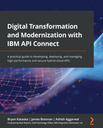
- Verify that the images are loaded in the Docker repository by executing this command:
docker image ls

Figure 4.1 – The Docker image ls command results
- Make sure that the apic-lte-win_10.0.1.5.exe directory is in your environment's PATH.
- Ensure that all LTE container components are installed (as shown in Figure 4.2) by executing this command:
apic-lte-win_10.0.1.5.exe status
This will get the following output:
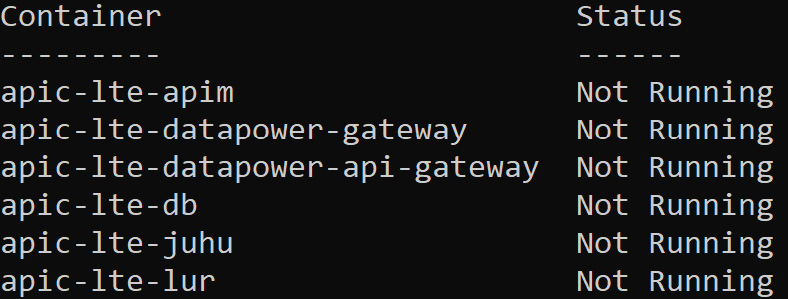
Figure 4.2 – LTE components
- Start Docker containers for APIC by executing this command:
apic-lte-win_10.0.1.5.exe start
Note
There are a number of switches that are applicable to the start command. Some of the main switches are discussed next:
--keep-config: By default, apic-lte-win_10.0.1.5 start, without the --keep-config switch, deletes all the previously published API/Product information from the configuration DB and re-initializes the LTE configuration. Essentially, LTE starts with an empty backend DB that does not contain the APIs and Products that may have been published during an earlier run of LTE. To retain the previously published configuration, use the --keep-config switch. When using --keep-config, any other switches (for example, --datapower-api-gateway-enabled --datapower-gateway-enabled) specified for the start are ignored, and instead the same flags that were used during the earlier start are used. The start switch starts the DataPower API Gateway by default.
- After the successful start of the LTE environment, you should see a response similar to Figure 4.3 in your console:

Figure 4.3 – LTE environment start results
You will be using a number of the values that are displayed in Figure 4.3. Copy these values to a notepad. They will be used later. There are two important values not displayed here. These are DataPower web admin URLs for DataPower API Gateway and DataPower Gateway (v5 compatible). Sometimes, during your API testing and debugging, you might have to refer to the gateway logs. In such cases, having access to these URLs will be beneficial. These URLs are as follows:
- https://localhost:9090/ (v5 compatible)
- https://localhost:9091/ (API Gateway)
You can log in using admin/admin credentials on both these URLs.
LTE verification will be discussed next.
Verification
It is important that you perform some basic verification of the LTE installation that you just completed:
- Check the status of all the services to make sure that all the containers are running by executing the following command:
apic-lte-win_10.0.1.5.exe status
This will give the following output:

Figure 4.4 – LTE environment status results
- You can also consult the log file for each of these LTE containers by using the following command. Consulting the container log files might be required if you face any problems/errors while publishing and testing your APIs later:
docker logs -f -n 10 container-name
Replace container-name with the name of the container whose logs you want to monitor. Container names can be retrieved from the command (apic-lte-win_10.0.1.5.exe status) described in the previous step. They are provided in the Container column of Figure 4.4.
This concludes the verification of your LTE.
Now that you have installed the Designer and the LTE environments on your workstation, it is time for you to connect these two tools together. As you will recall, Designer helps you in the development of your APIs and the LTE provides an execution runtime for your APIs. You will see these tools in action.
Connecting Designer to the LTE
Designer allows you to connect to multiple environments. You can connect Designer to the LTE or to the API Manager cloud environment. In all cases, you should maintain the version compatibility between Designer and the execution environment (the LTE or API Manager) being connected to. You will now connect Designer to the LTE:
- Open Designer. Click on Open a Directory (Figure 4.5). You will provide the path to a local directory where your APIs and Products definitions can be stored. This is typically your development workspace.

Figure 4.5 – Local workspace directory path
- On the New API Connect connection screen (Figure 4.6), provide information about connecting to your LTE. This information was gathered earlier, during the setup of the LTE environment. You can always retrieve that information by executing the apic-lte-win_10.0.1.5.exe status command. Click Submit.

Figure 4.6 – LTE environment host URL
- On the login screen, provide the username (shavon) and password (7iron-hide) information. Click Log in. Your Designer should now be connected to the LTE!
- Before going further, it is important for you to quickly familiarize yourself with some key navigation areas of the Designer window. Key areas of Designer are marked with numbers in Figure 4.7 :

Figure 4.7 – API Designer interface
The details of the key areas of the Designer are provided in the following table:

Table 4.1 – Designer Interface's key navigation areas
It is time to take a quick recap of the things you have accomplished thus far. By now, you have set up on your workstation the Designer component (for API development) and the LTE (for API execution). You have also connected Designer to your local LTE. Then you took a quick overview of Designer's main screen and understood the main navigation areas.
The Designer and LTE components provide a great way to perform localized API development. These two tools offer a perfect starting point for many developers. They should be sufficient for you to start API development. Yet, many developers choose to use a more comprehensive web-based API Manager tool for their API development needs. API Manager comes with multiple functionality enhancements, such as working with OAuth providers, user-authentication registries, and a unit test harness.
With Designer and the LTE now in place, it is time for you to start putting these tools to use. The following sections will expose you to the fundamentals of API development using the tools you have set up.
Creating APIs
APIC supports OpenAPI design, multiple security standards, has an extensive repository of Out-of-the-Box (OOTB) Policies, and supports various logic constructs. This really enables developers to develop advanced APIs.
It is practically impossible for a single book to cover every feature and function provided by APIC and all the use cases that it can solve; the concepts discussed in the following sections should make it easier for you to undertake API development with much more confidence. And for the preparation of that journey, you will learn about the following in this part of the chapter:
- OpenAPI design
- Creating a simple proxy API
- Testing APIs
- Variable usage
- Enhancing APIs by applying policies
- Error handling
Let's explore each topic in detail.
What is an OpenAPI design?
The OpenAPI Specification (OAS) is the grammar to the language of the API. Grammar is a sign of a language's maturity and advancement. Mature APIs use OAS grammar rules and syntaxes to describe themselves. Any API written following these grammar rules is called an open API.
In other words, an OpenAPI document is a document (or set of documents) that defines or describes an API using OAS. OAS specifies a standard format for describing a REST API interface in a standard, vendor-neutral, and language-neutral way. The OAS standard is necessary because it helps in the API economy's growth through increased API consumers' participation (after all, standards-driven communication leads to more participants).
OAS is the most widely adopted specification today when it comes to describing RESTful APIs. It is worthwhile mentioning that OAS is not the only specification out there. Some notable mentions are RESTful Service Description Language (RAML – https://raml.org/) and API Blueprint (https://apiblueprint.org/).
An API definition (or an OpenAPI document) is written in a file that can either be a JSON or YAML formatted document. The main sections of an OpenAPI document from an OAS 3.0 perspective are Info, Servers, Security (Scheme and Enforcement/Security), Paths, Operations, Parameters, and Responses.
Security Definition and Security Enforcement:
Security Scheme: This is where you can specify the security implementation details such as authentication URLs, OAuth settings, and API keys' header names. It is worth highlighting that creating a scheme does not enforce that scheme on an API consumer. You can define multiple schemes in your API Proxy but have only one of those schemes enforced upon that proxy's consumers. The enforcement of the scheme is done by Security Enforcement.
Security Enforcement or simply called Security: This is where you enforce the Security Scheme on the API consumer.
At the time of writing this chapter (September 2021), OAS 3.1.0 is the latest candidate release. These are the following things that you should be aware of:
- APIC 10.x supports OAS 3.0 with certain limitations on both the user interface (Designer and API Manager) and DataPower API Gateway. Refer to IBM documentation for limitations: https://www.ibm.com/docs/en/api-connect/10.0.1.x?topic=definition-openapi-30-support-in-api-connect
- OAS 3.0 is not supported by DataPower Gateway (v5 compatible). OAS 3.0 API support is provided by the DataPower API Gateway only.
- APIC has extended the OAS and has added some of its own message processing policies to support complex message processing.
Since APIC supports OAS, any API definitions you build using OAS can be imported directly into APIC. You can view the OAS design of your API by clicking the Source icon on the Design tab. Refer to Figure 4.8:

Figure 4.8 – OpenAPI Source icon
You can update the source code within the source view or use the more user-friendly form view.
Note
There are two important distinctions to be made here:
API Proxy: An API proxy, in general, concerns itself with the implementation of an API definition in an API Management tool such as APIC. Though it is certainly possible to write an API proxy completely within APIC, without it having to connect to a backend service provider, you would typically implement an API proxy that proxies a backend service.
API: An API will mostly be related to the implementation of the service definition by a backend service provider, outside of the API management tool.
It is certainly possible for an API to deviate from the API definition that is proxied by an API Proxy. And that is where various Policies and logic constructs of APIC come into play. Policies and Logic constructs map the API definition of an API Proxy to the definition provided by the actual API.
You will now begin the process of creating an API Proxy using APIC.
Creating an API Proxy
The previous section was about understanding the API's grammar. This section will be about building the sentences and starting to put those grammar rules into practice. You will do that by creating an API Proxy using Designer and then test that on the LTE. It is worth mentioning that you can follow the steps provided in this section on the API Manager interface as well. Steps on the API Manager are quite similar to the steps provided for the LTE environment.
Prerequisites
- Make sure that you have Designer and the LTE installed and configured on your workstation.
- Ensure that you can access the https://stu3.test.pyrohealth.net/fhir/Patient/d75f81b6-66bc-4fc8-b2b4-0d193a1a92e0 resource from your workstation. The API Proxy that you will soon build uses this backend service URL.
API development
It is time for you to start with the API development:
- On the Designer's home screen, click on the Develop APIs and products tile. Click Add | API (from REST, GraphQL or SOAP).
- Stay on the default OpenAPI 2.0 tab.
- Notice the various API types (Figure 4.9) that can be created. You will learn how to implement the SOAP Proxy and REST proxy using a WSDL file in Chapter 5, Modernizing SOAP Services. In Chapter 9, Building a GraphQL API, you will learn how to create a GraphQL proxy.
You will be creating your first API utilizing an existing target service.
In the Select API type view, select the From target service option and click the Next button.

Figure 4.9 – API types
- In the Info section, specify the following information (Table 4.2):

Table 4.2 – Info section values for the new API
- Click the Next button. In the Secure section, keep the options of Secure using Client ID and CORS selected.
- Click the Next button, where APIC will display the summary of the API generation process.
- Click the Edit API button to further configure your API definition.
- Review the various sections (General, Paths, Definitions, and so on) under the Design tab (Figure 4.10).

Figure 4.10 – Design tab user interface
Figure 4.10 shows how APIC has organized OAS under various key sections. By clicking on each section of the Design tab and reviewing various parameters of each section, you will see how easy APIC makes it to create the OAS source, instead of typing it all into a file. Of course, you can click on the source view icon to review the OAS in a file format. As you click through the various sections under the Design tab, take time to correlate much of the information in these sections (General | Info, General | Schemes List, General | Security, Paths) with the OAS that you learned about in the OpenAPI design section of this chapter.
APIC provides comprehensive security coverage for APIs. As was discussed earlier, in the OpenAPI design section of this chapter, APIC supports multiple security schemes. You will be getting a comprehensive tour of APIC's API security features in Chapter 7, Securing APIs. For now, you will keep it simple and secure your API using the API key security scheme. Go ahead and review the security definitions of your API. Go to the Design tab | Security Schemes section. You will note that it already has an apiKey with the name clientID. This was created because you kept the option of Secure using Client ID selected in the earlier step. Go ahead and further strengthen your API's security by adding a definition for the client_secret type apiKey.
- Click the Plus icon next to the Security Schemes menu item. Provide the values highlighted in Figure 4.11. Once complete, click on Save.

Figure 4.11 – client_secret apiKey
Note
The X-IBM-Client-Id and X-IBM-Client-Secret header names are not APIC specific. You can substitute these with any other names, for example, X-ABC-Client-Id or X-ABC-Client-Secret. It is still a good practice to use the standardized names of X-IBM-Client-Id and X-IBM-Client-Secret.
Enabling API security
Now that you have the security schemes for client_id and client_secret, it is time to use them in your API's Security. You will remember from our earlier discussion that Security Scheme creation and security enforcement are separate steps. Security scheme creation is followed by the security enforcement step. In the previous step, you created the security scheme. Now you will apply that scheme to your API's security.
- Go to the Design tab | General | Security | clientID. On the Security Requirements screen, select the clientSecret scheme. Click the Submit button.
- Go to Paths in the navigation pane. Designer has a default Path (/) definition created. You will be modifying this default definition.
- Click on / under Paths. Click on the Update button. Change Path to /Patient and click Save. Refer to Figure 4.12. This path will be appended to the Base path defined in the earlier step (refer to Table 4.2), for example, the URL for invoking this API will be https://localhost:9444/localtest/sandbox/fhir/Patient.

Figure 4.12 – Setting Path
- Delete all Operations except GET.
- Click the Save button.
- Locate and choose the Gateway tab. You will notice an invoke policy as shown in Figure 4.13:

Figure 4.13 – An Invoke policy in the Gateway Policies
The invoke policy instructs APIC to proxy the API to the endpoint you provided earlier (https://stu3.test.pyrohealth.net/fhir/Patient/d75f81b6-66bc-4fc8-b2b4-0d193a1a92e0).
Congratulations! You have just created an API Proxy that has been deployed for testing.
Now that you have created your first API Proxy on APIC, it is time to run some tests and see this API Proxy in action.
Testing APIs
There are multiple methods to test an API Proxy. You can either use external tools such as Postman, cURL, or SoapUI, or you can use the test capability provided by the APIC platform. You will learn how to use the test facility in APIC so that you can understand the test suite capabilities of the APIC platform.
Testing Note
A more comprehensive testing facility will be introduced in Chapter 13, Using Test and Monitor for Unit Tests, where you can build unit tests that can be executed in your DevOps pipelines.
Before you can test your API, it needs to be put online. To put your API online, simply click on the Test tab as shown in Figure 4.14:

Figure 4.14 – Using the built-in test feature
You will notice in Figure 4.14 that the GET operation you created is already displayed. Some other interesting points in the URI are as follows:
- localtest in the URI is the organization name.
- sandbox in the URI is the catalog environment where the API was deployed.
- The base path you defined earlier is also in the URI followed by the REST target.
Other features you will see are the headers that are already available. The generated client id and client secret that were provided when you started the LTE are automatically inserted. The APIm-Debug header is set to provide you with detailed debugging information.
Testing your API Proxy
It is time to test the API Proxy. Here's how:
- While still on the Test tab in Figure 4.14, click Send. You should now receive an HTTP 200 successful response with the associated payload displayed in the Response section. That is shown in Figure 4.15:

Figure 4.15 – HTTP 200 response with payload
- You can click on the Headers tab to see the header used or the Trace tab to see the tracing of your policies. In this case, you only had the invoke policy, but in future cases, you will be able to see how APIC traverses through multiple policies.
You have completed the testing of your API Proxy. That was easy.
Note
The test capability you just completed only works on the DataPower API gateway service. This is the default gateway when you create your APIs. If you are supporting the previous version 5 edition of APIC and you want to specify DataPower Gateway (v5-compatible), go to the Gateway tab | Gateway and portal settings in the navigation pane of your API. Scroll to the Catalog Properties section and you will find the Gateway selection option. Choose datapower-gateway.
By default, when you test an API with the Test tab, a range of test parameters are pre-configured, for example, a default Product is automatically generated, to which the API is added, and that Product is published to the sandbox catalog. You can configure testing preferences such as the target Product and target Catalog. Some of these configuration options are not available in LTE though.
You should now feel sufficiently prepared to embark on the journey of enriching your API Proxy with Policies and Variables. Policies and Variables are the building blocks for adding functionality to your Proxies. These are often used to add custom logic, transformation, routing, logging, and security capabilities to the Proxies. Variables and Policies are important to understand so that you can use them to enhance an API Proxy's functionality. You will begin by learning about variables.
Using variables
Like any mature application development framework, APIC also supports various variable types to help manage/manipulate the data being passed in an API and control API's Policies' behavior. There are two types of variables supported by APIC: Context variables and API properties.
Context variables
These are the variables that are relevant during the context of an API call. Therefore, their scope is also limited to the context of a specific API call on the runtime gateway. There are several context variables available. You can refer to the complete list at https://www.ibm.com/docs/en/api-connect/10.0.1.x?topic=reference-api-connect-context-variables.
Context variables are categorized into the following categories:
Each category contains information about a particular aspect of an API call. Here are some of the most used categories:
- api: Provides API metadata, for example, API name, version, operation path, and provider organization information. One of the important elements of interest in this category is api.properties.propertyname. propertyname can be any custom property (catalog specific) defined for the API. API properties will be discussed in detail in the next section.
- client: Provides information about the client's organization information and the client's application that issued the request to the API.
- message: One of the most heavily used categories. This is the payload of the request or response message. Note that this is different from the request category (discussed next). Loosely, the message category represents a message as it moves in processing policy. You can read/write data to the message category. If you need to make any modifications to request and response payloads, then the message category is your playground.
- request: This represents the original HTTP request, its headers, URI, verb, parameters, and so on. This is read-only. And this is the fundamental difference between the message and the request category. HTTP request headers can be modified in the preflow policies.
- system: Provides system data and time information of the gateway.
Of course, you may not need to use all the different categories, but you should be aware of some of the more useful context variables. These are shown in Table 4.3.

Table 4.3 – Important context variables
You can read more about context categories and some associated variables of the message and request categories at https://www.ibm.com/docs/en/datapower-gateways/10.0.x?topic=object-context-api-gateway-services.
Now that you know some of the useful context variables, you should become familiar with how API properties are used.
API properties
API properties are used by the gateway to control the behavior of policies. One of the most common uses for custom API properties is to specify environment-specific URLs. In a typical APIC configuration, each catalog generally represents a deployment environment, for example, Development, Test, and Production.
Further, each catalog has a specific gateway URL assigned to all the APIs executing in its context. You can use API Properties to specify environment-specific backend URLs (for each catalog) in the API definition and then use that property (instead of hardcoding the URL) in the invoke policy.
This will result in a dynamic API configuration. You will soon build an example to get a better understanding of this. You will use the API Proxy that you created earlier to create a Catalog specific property, assign it a backend URL, and then use that property through inline referencing (more about this shortly) in the Invoke Policy:
- Open your patient-information API in Designer.
- Go to the Gateway tab | Gateway and portal settings in the navigation pane | Properties.

Figure 4.16 – Adding API properties
You will notice there already is a target-url property defined in Figure 4.16. You will create a new one for demonstration purposes.
- Click the plus icon button to create a new custom API property.
- In the new property view, provide the Property Name field with a value of patient-target-url.
- Now go to Catalog Properties in the navigation menu. Click the plus icon button.
- Select Sandbox in the Catalog Name (Key) field. Click Create. Now you will be able to override properties for the Sandbox catalog. Scroll down to the Properties Overrides section and click the Add button.
- Provide the following values in the new property override view:
- Property Name to Override (Key): patient-target-url
- patient-target-url (optional): https://stu3.test.pyrohealth.net/fhir/Patient/d75f81b6-66bc-4fc8-b2b4-0d193a1a92e0
- Click the Create button and save your API. You just created a custom API Property with the name patient-target-url and have overridden its value in the Sandbox catalog. Since you are working with LTE, Sandbox is the only catalog available to you. Typically, in API Manager, you will have access to multiple catalogs (if you have been granted access by your administrator). In that case, you can add more catalogs to your custom property and assign them different URLs.
- Now that you have created a custom API Property in your Sandbox Catalog, it is time for you to use this property in your API. Go to the Policies view in the Gateway tab of your API. Click on the only Invoke policy that you see on the panel. A panel will display on the right that shows parameters intended for the Invoke policy. Remove any existing value from the URL field of the Invoke Policy and replace it with $(patient-target-url). Refer to Figure 4.17:
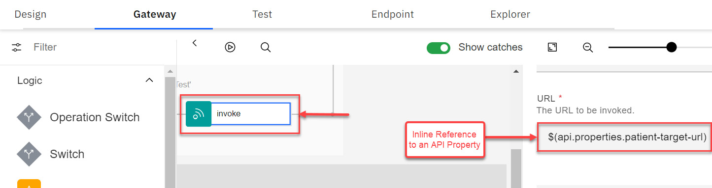
Figure 4.17 – Inline referencing of a custom API Property
Inline referencing is a variable or property referencing technique using the $(variable) format. Here, variable is the name of a context variable or an API property that is utilized. Often this method is used to construct dynamic URLs in an invoke policy and for building switch conditions. You will see another example of an Inline referencing method when we introduce you to the switch policy later in this chapter.
- Save the API, click on the Test tab, and run the test again. You should see the same result as before.
You have learned about the concept of variables and API properties that are utilized in APIC. Many of these variables are system variables. They allow you to access meta-information about an API call, for example, API version, base path, request payload, and headers. You also reviewed the concept of API Properties that you can leverage to manage environment-specific configuration.
You have just seen an example of an Invoke policy using API Properties. There is more to learn about policies, so you will do that next.
Adding policies
What are policies? Policies are pieces of configurations that invoke a specific type of action (depending on the type of policy) on a message. There are Built-in policies that come pre-packaged in the APIC solution. They are divided into five categories:
- Logic: These policies control the flow of the API by providing conditional coding aspects to your APIC such as if, switch, Operation-switch, and catch.
- Transforms: Provide the ability to transform payloads using various methods or manipulate headers. In Chapter 8, Message Transformations, you will work exclusively with these policies.
- Policies: Provide the ability to route, inspect, validate, log, set limits, and apply GatewayScript coding. This chapter will introduce you to some of these policies.
- Security: Apply client and user security as well as applying JWT capabilities. In Chapter 7, Securing APIs, you will work with these policies in detail.
- User-defined policies: Build your own policies. The user-defined policies feature is available only with the on-premises offering of APIC. In Chapter 12, User-Defined Policies, you will learn how to create your own custom policies.
These policies support your API use cases with data transformation, message routing, securing, validation, and logging. Essentially, these Policies provide building blocks to truly enhance your API's capability. For instance, you may use these Policies to Map (transformation), Invoke (message routing), Validate (schema validation), apply Client Security/Validate JWT (for security), Log (to control logging information to the analytics server), and Throw (for exception handling).
It is worth mentioning that Catch is not a policy. Catch is implemented by IBM extensions to OAS. You will be introduced to the interplay of the Throw policy and Catch IBM extension through an example later in this chapter.
You should review the documentation for details of all the different Built-in Policies: https://www.ibm.com/docs/en/api-connect/10.0.1.x?topic=constructs-built-in-policies.
Policies are gateway type-specific. All Built-in policies, except for the Validate Username token policy, are available as part of DataPower API Gateway. There are several policies that are not available for DataPower Gateway (v5 compatible). You can review the Gateway specificity of the policies at https://www.ibm.com/docs/en/api-connect/10.0.1.x?topic=constructs-built-in-policies.
A sample screenshot to show you how policies are organized in an API is shown in Figure 4.18:

Figure 4.18 – Policies and Logic constructs
As you can see, you can apply multiple policies to a single API. To help your understanding of policies, you will be introduced to a few of the policies and how they supplement your API. In this chapter, we are focusing on the Invoke policy. It is the most important policy so you will learn about it now.
The Invoke policy
The Invoke policy is one of the most heavily used policy types and probably the most feature-rich too. It can often be used (depending upon the nature of the backend service provider) by keeping its default settings and by only specifying the URL property. But other than its basic usage, the Invoke policy provides many advanced properties to control the execution of the backend service call. You will learn about some of these advanced properties by implementing some new behavior.
Handling error conditions on a failed invoke
Within the Invoke policy, there are capabilities that instruct how the Invoke policy will behave on error conditions. A typical error condition would be a backend service that is experiencing slow response times. It is possible that your proxy needs to respond back to the consumer with a response (success or failure) within a defined Service-Level Agreement (SLA). If the SLA is shorter than the Invoke policy's default Timeout value of 60 seconds, an error occurs. This scenario can be easily handled by leveraging the Timeout and Stop on error properties found within the Invoke policy setup. Here is a brief description of these properties:
- The Stop on error property provides an option to stop the message flow's execution when one or more pre-defined errors (for example, ConnectionError, SOAPError, OperationErrror) is encountered during an Invoke policy's execution. If a catch flow is configured to handle these errors, then that catch flow is executed. If there is no catch flow configured, then the message flow processing continues, thereby ignoring the error. You add a catch flow by first enabling the Show catches slider. That will display an empty Catches box. When you click on the Catches box, it opens the properties box to allow you to add a new catch or add a default catch. This is shown in Figure 4.19:

Figure 4.19 – Enabling Catches
When you click on Add catch, you have various catch conditions to choose from. When you choose one of the 11 catch types, it updates the Catches section with the selected catch type and allows you to configure how to handle the catch. This is shown in Figure 4.20:

Figure 4.20 – Adding a catch
You can add more catches to handle other conditions.
- The Timeout property is the time (in seconds) that the Gateway waits to receive a reply from the backend service.
You will now build an example to see the Stop on error and Timeout properties in action:
- Open the patient-information API in Designer. Open the Gateway tab.
- Enable the Show catches section of your API as shown in Figure 4.19. Click anywhere on the Catches block. A catch view will open. Add a ConnectionError catch by clicking on the Add catch button and selecting ConnectionError.
- Drag a GatewayScript policy onto the ConnectionError catch. This is shown in Figure 4.21:

Figure 4.21 – Applying error coding to handle error
- Enter the following code into the editor of your newly added GatewayScript policy. You can also fetch this code (errormsg.js) from this chapter's GitHub repository:
var errorName = context.get('error.name');
var errorMessage = context.get('error.message');
var errorResponse =
{
"name": errorName,
"message": errorMessage
};
context.message.header.set('Content-Type',
"application/json");
context.message.body.write(errorResponse);
Click Save to save your changes.
- Click on the Invoke policy, scroll down the properties page, and check the Stop on error checkbox.

Figure 4.22 – Configuring Stop on error
When you click on search errors …, a dropdown with error types is displayed as shown in Figure 4.22. Choose ConnectionError to match up with the catch you just configured.
This completes your configuration of handling ConnectionError when such an issue is encountered in the API Proxy. With your API now configured to handle the connection error issues, you will next do a temporary configuration to create this error condition. This error condition will be created by utilizing the Timeout property of the Invoke policy.
- The Timeout property (Figure 4.23) has the default timeout value of 60 seconds. You should set it to 10 seconds.
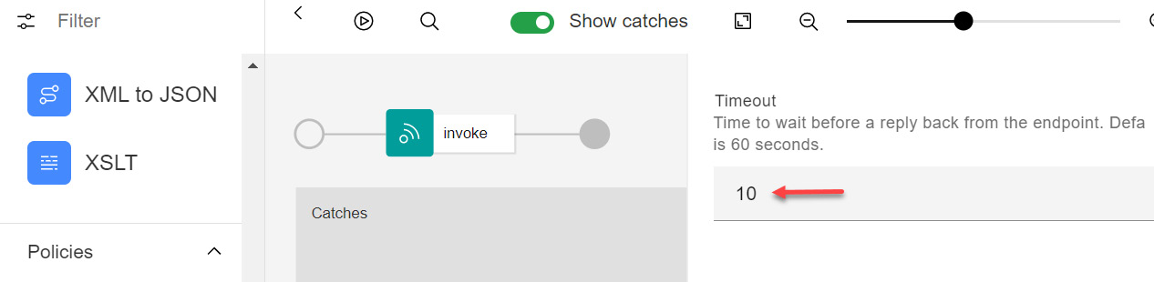
Figure 4.23 – Invoke policy's Timeout property
- The last thing that you need to do is force a timeout. This will be done by updating the patient-target-url API property. Use a URL that will time out. Change the API property value from https://stu3.test.pyrohealth.net/fhir/Patient/d75f81b6-66bc-4fc8-b2b4-0d193a1a92e0 to https://stu3.test.pyrohealth.com/fhir/Patient/d75f81b6-66bc-4fc8-b2b4-0d193a1a92e0 (note the change from .net to .com in the server name). Save the changes to your API.
- Next, click on the Test tab. Send the request. After about 10 seconds, you should get the backend server timeout and observe the ConnectionError catch in action.

Figure 4.24 – Error caught – "Could not connect to endpoint"
Figure 4.24 shows the ConnectionError response "Could not connect to endpoint" in JSON. You have successfully tested the Stop on error and Timeout properties within an Invoke policy.
Remember to change the patient-target-url property back to https://stu3.test.pyrohealth.net/fhir/Patient/ for future testing.
Next, you will learn about another important property of the Invoke policy that is frequently used, and that is changing the HTTP method of the outgoing request (to the backend service).
Changing the HTTP method in the Invoke policy
Typically, an API proxy's operation's method should match the backend service's HTTP method. Sometimes you might come across a scenario where the backend service that you are proxying supports an HTTP method that is different from what is exposed by your API proxy. A typical example is exposing a REST API (GET) method that proxies a SOAP backend service. It is common for SOAP services to be exposed via a POST method irrespective of whether they fetch the results (typically GET) or perform other updates (POST/PUT/DELETE). In such a case, you can use the HTTP Method property (Figure 4.25) of the Invoke policy to match the HTTP method that is supported by the backend service.

Figure 4.25 – Invoke policy's HTTP Method property
You may be wondering about the Keep option. Keep is the default value and it means that the incoming HTTP method should be continued as the HTTP method to the backend service. You will learn more about these options in, Chapter 5, Modernizing SOAP Services.
Often there are strict requirements around the header and parameters that can be passed to the backend service. The Invoke policy provides a couple of properties that can be used to meet such requirements. You'll see an example of this next.
Header Control and Parameter Control
The Header Control and Parameter Control properties control the request's headers and parameters that get passed to the backend service.
Often, you will have a requirement to block certain header values from being passed to the backend service called by your Invoke policy, for example, blocking the API request's X-IBM-Client-ID/X-IBM-Client-Secret values from being passed to the backend service. You can easily handle such a requirement using the Header Control property:
- Open the patient-information API in Designer. Open the Gateway tab | invoke Policy | Header Control property. Click Add blocklist as shown in Figure 4.26:

Figure 4.26 – Header Control
- Add the value ^X-Environment$ to Blocklist. This instructs the gateway to copy all headers except for X-Environment to the target service.
- Save and Publish your API.
- Click on the Test tab to run your API. Add the following headers to the request (refer to Figure 4.27):
X-Environment header with a value of Skip Me
X-Book-Reader header with a value of Allow Me
`

Figure 4.27 – Adding new headers in the Test facility
- Click Send to send the request. When the request completes, click on the Trace tab | Invoke policy | Advanced slider. Refer to Figure 4.28:

Figure 4.28 – Reviewing Trace for headers
This will allow you to see the entire flow from the initial request to the call to the backend and the resulting response.
- Scroll through the output and expand the headers to look for your X-Environment and X-Book-Reader headers. Notice that all headers except for X-Environment are passed, including your X-Book-Reader header, to the target backend service as shown in Figure 4.29:

Figure 4.29 – Header omission verification
This example demonstrated the use of the header control property of the Invoke policy and how it can be used to block certain headers from being passed to a backend service. You can use the same method to filter or allow query parameters using the Parameter Control property of the Invoke policy.
Another important capability of the Invoke policy is its ability to utilize variables and properties inside its URL property. This allows for the dynamic building of the backend URL. You will review this capability through an example in the next section.
Accessing variables and properties in an Invoke Policy
An Invoke policy's target URL is often built using variables and properties. Earlier, in the Create an API Proxy section, you created a proxy that utilized a static backend URL containing a hardcoded patient-id value (d75f81b6-66bc-4fc8-b2b4-0d193a1a92e0). You will now improve upon that proxy by removing the hardcoding of the patient-id value. Instead, you will now define patient-id as a parameter in your API's definition and pass the patient-id value with the request message. You will then access this patient-id parameter using the Inline Referencing technique and dynamically build the backend service URL of the Invoke policy using the captured value of patient-id.
Before diving into the example, it is important for you to understand key Parameter types. Parameters represent the values that come as part of an API's request. The following are the main types:
- Path type: Parameters defined at the path level are the variable parts of a URL path. These parameters cannot be omitted from the URL path. They are used to point to a specific resource. For example, a parameter defined as /customers/{customer-id} can be accessed as /customers/123 by an API consumer. In this case, API consumers will get details of the customer resource represented by customer-id=123. You learned about path-based Parameter usage in the example Accessing variables and properties in an Invoke Policy.
- Query type: Parameters defined as a query type are typically used to sort, filter, or paginate the resources. For example, a query parameter defined as /customers?firstName=Drew can apply a filter of firstName=Drew to the complete dataset before returning the subset data results to the API consumer.
- Header type: Header type Parameters can also be used to pass values to an API flow. You can use this type to pass custom values, such as security headers, to an API flow.
Now that you understand the key parameter types, it is time to create a new example of a REST API proxy:
- On the Designer tool's home screen, click the Develop APIs and products tile. Click Add | API.
- Ensure that OpenAPI 2.0 is selected.
- In the Select API type view, select From target service and click Next.
- In the Info section, specify the following information:

Table 4.4 –API proxy details
- Click Next. In the Secure section, unselect Secure using Client ID but keep CORS selected.
- Click Next to create your API definition.
- In the Summary section, click Edit API to further configure your API definition.
- Go to your API's Design tab | Paths section in the navigation pane. Change the default path (/) to /patient/{patient-id}.
- Add a new path parameter by clicking on the plus icon next to Path Parameters (0). Create a new parameter with the name patient-id and assign it the values as per Figure 4.30.
- Delete all the operations except GET. Click Save to save the definition.
A completed screen is shown in Figure 4.30. It is important to understand all the things that are highlighted in this figure. There is a lot happening here. It is important to note that the parameters Located In path are always Required. Another thing to note is that the parameter defined in the path's Name {patient-id} is inside curly braces and that it matches the value in the Name field.

Figure 4.30 – Path, Operation, and Path parameter creation
Now you need to set the target-url property to the backend endpoint.
- Go to API Gateway tab | Gateway and portal settings | Properties. Click on the target-url property. Remove the value from the Property Value (optional) textbox.
- Override this target-url property value by creating a catalog property in the sandbox catalog. Name this catalog property target-url and assign it a value of https://stu3.test.pyrohealth.net/fhir/Patient/. Click Save to save the definition.
- With this setup done, let's use the Inline referencing technique to construct the target URL for your Invoke policy. Go to the Gateway tab of your API and click on the only invoke policy on the canvas.
- Remove the URL property $(target-url) of the Invoke policy and enter the following value:
$(api.properties.target-
url)/$(request.parameters.patient-id)
Note
You should understand the format of $(api.properties.target-url)/$(request.parameters.patient-id). This technique is called Inline referencing. You are using Inline referencing to access an API property (target-url) and a request Path parameter (patient-id) that you just define. You are also combining the two values to construct the final backend target URL.
- Click Save to save your API. Enable the Online slider to publish your API.
- Click on the Test tab.
- You can now test the API proxy. Note the absence of the "X-IBM-Client-Id" and "X-IBM-Client-Secret" headers:
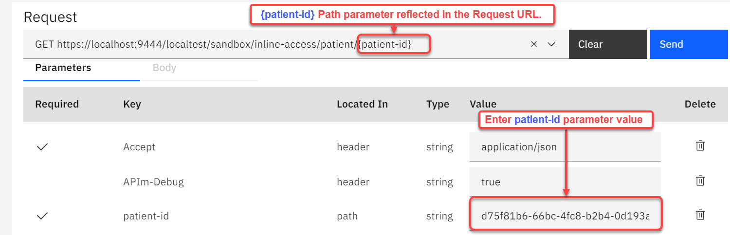
Figure 4.31 – Adding the value of patient-id
As you can see in Figure 4.31, the value of patient-id is required. Enter the value "d75f81b6-66bc-4fc8-b2b4-0d193a1a92e0" in the highlighted area. This value is the patient-id path parameter that you defined earlier.
- Click the Send button and review the response.
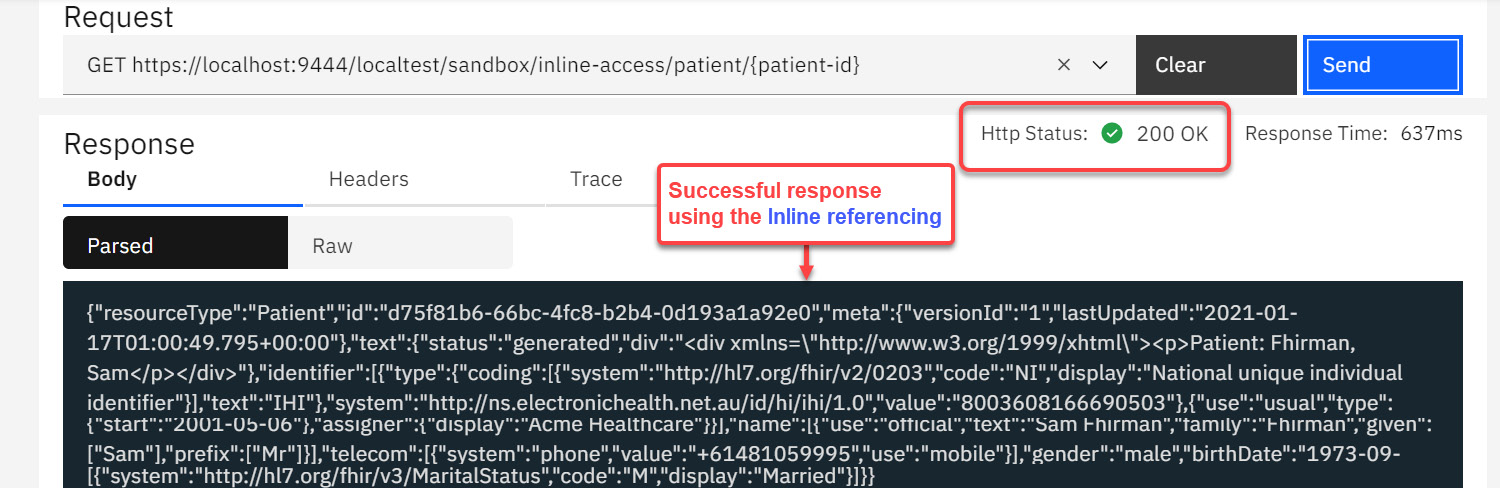
Figure 4.32 – A successful test using Inline referencing
The preceding steps demonstrated the method of using inline referencing to dynamically build a target URL. As mentioned earlier, Inline Referencing coupled with API Properties is among one of the most used methods to dynamically build the target URL. Make sure that you develop a good understanding of this technique.
Note: v10.0.1.5 enhancements
The Invoke policy has introduced the ability to reuse HTTP connections through the persistent connection property.
That was a comprehensive look at the Invoke policy and some of the crafty things you can do with it. We are sure that you can think of many more use cases. Some of those use cases might lead to you using other policies provided with APIC. One other important policy in the APIC arsenal is the switch policy. You will be introduced to this next.
Building a Switch policy
You will make changes to the inline-access API that you recently created. You will use a Switch policy and make a determination based upon a header variable (Environment) to process different branches of the message processing flow. Begin by opening the inline-access API in Designer. Navigate to the Gateway tab to review the single invoke policy:
- Click on the Invoke policy to bring up the property pane. Notice that the title is invoke. Replace the title invoke with the more readable title Production invoke. Making this change helps with the identification of the responsibility of the policy. You must follow the practice of giving meaningful names as per the identification of the responsibility of your policies and variables. You see that this new title is represented on the canvas as shown in Figure 4.33. Click Save to save the change.

Figure 4.33 – Adding readable code
- Next, we want to add our switch logic policy. Drag the switch logic policy to the left of the Production invoke policy. You will drop it when a small square appears. Refer to Figure 4.34:

Figure 4.34 – Dragging switch before the Production script
You will now see a switch policy on the pane and the property screen on the right with Case 0 set to a condition of true.
- Change the Case 0 condition using an Inline reference of $header('Environment')='Production':

Figure 4.35 – Adding case to switch
- Click on Add case to add our other leg to the switch. Using the same process as in step 3, change the value of Case 1 from true to message.headers.Environment = 'Test'.
- In Figure 4.36, you can see how the switch has changed to show the two possibilities:

Figure 4.36 – Adding a second case
You will notice that conditional logic for each case is built a bit differently using Inline references to the Environment request header. Notice the use of the $header('Environment') and message.headers.Environment expressions. $header is just a functional extension of the variable message.headers.name in standard JSONata notation. You can use either of these techniques.
You will want to add a second Invoke policy to represent the Test environment.
- Drag the Production invoke policy to Case 0 as shown in Figure 4.37. Drag and drop another Invoke policy for the Case 1 branch and change its title to Test invoke. Make sure that the URL for both Production invoke and Test invoke policies is set to $(api.properties.target-url)/$(request.parameters.patient-id). Click Save to save your API.

Figure 4.37 – Dragging Production invoke and Test invoke
You have configured your first switch policy. Your screen should look like Figure 4.38. This example assumes that the client application is passing a custom header, Environment, with the request.

Figure 4.38 – Use of Inline referencing in Switch conditions
Review the highlighted sections in Figure 4.38. You will notice that conditional logic for each case is built using inline references to the Environment request header.
It is time to test your API. You already know that the two Invoke policies point to the same service. So how will you know which branch your Switch policy took? You are going to learn how to use the Trace facility to answer this question.
- Click on the Test tab and add the Environment header. Set the header to Test. Also set Patient-ID to d75f81b6-66bc-4fc8-b2b4-0d193a1a92e0. Click Send.
You should get the same results as before. But since the Invokes looked identical, how do you know whether it really executed Case 1? The next step shows you how.
- After you run your test, click on the Trace tab. You will see the graphic that shows you which case statement was run. The other statement is grayed out. Figure 4.39 shows that result:

Figure 4.39 – Using Trace to determine the execution of Switch
You have now learned another valuable technique for accessing Parameters and API properties through the Inline Referencing method, as well as how to take advantage of the built-in testing and tracing capabilities of API Connect.
The last feature on the Invoke policy will be how to capture response objects and merge the information. Service chaining is common with APIs.
Service chaining using double Invokes
Under-fetching is a common symptom when services are created where the consumer needs to make multiple calls to obtain the results they desire. Service chaining in APIC can be created to handle such situations. You can build an API Proxy that acts as an aggregator of more than one backend services. You can implement the aggregator API Proxy by chaining calls to the backend services and combining the response data from each of these services into a single response to the consumer. Another solution for under-fetching is using GraphQL. You will learn about GraphQL in Chapter 9, Building a GraphQL API.
To build the aggregator response, you will use a combination of Invoke Policies and a GatewayScript Policy. For this use case, we will use the same backend service we have been using: https://stu3.test.pyrohealth.net/fhir/Patient/.
Previously, you have learned how to modify the titles of invoke policies, set path parameters for patient-id, and pass values to the Test capability of APIC. You will be doing that again with some slight modifications and the assistance of GatewayScript code. You can download patient-response.js from the GitHub site.
The approach you will be taking is constructing a new API definition and implementing two Invoke policies that return a different patient payload, followed by a GatewayScript that merges the responses of the two Invokes. The new skill you will learn is how to capture the response objects individually from each Invoke as query parameters. Once captured, you will filter specific fields from these responses and send a custom aggregated response back to the API consumer.
The patient-id values you will use are as follows:
- 9df54eeb-a9ac-47ec-a8f6-eb51dd7eb957
- 97e47441-b8b9-4705-bda7-248ae6ae2321
Here are the steps you should follow:
- Create a new REST API Proxy (from a target service) using the URL https://stu3.test.pyrohealth.net/fhir/Patient/. Name this proxy aggregation-service. Keep the default Base path value. Remove all the security definitions.
- In Design | Paths, create a path (/Patient) that takes two query parameters, patient-id1 and patient-id2. It should support a GET operation. Refer to Figure 4.40:

Figure 4.40 – Setting query parameters
- In the Gateway tab | Policies, update the existing Invoke and set Title to get patient 1 and the URL to $(target-url)/$(request.parameters.patient-id1). Scroll to the bottom of the invoke policy's properties and enter patient1-response in the Response object variable property. Refer to Figure 4.41:

Figure 4.41 – Setting the response object name
- Drag and drop a new Invoke to the right of get patient 1. Perform step 4 again but instead use the title of get patient 2, set the URL to $(target-url)/$(request.parameters.patient-id2), and set up the response object to patient2-response. Next, you will add the aggregation code to filter data.
- Drag and drop a GatewayScript policy to the right of get patient 2. Set the title to aggregate results. Download the GatewayScript's code (patientResponse.js) from this chapter's GitHub repository. Copy and paste the downloaded code into the GatewayScript as shown in Figure 4.42. Click Save to save your API.

Figure 4.42 – Aggregation GatewayScript
A quick review of the JSON code would be helpful. The code uses the context.get('response object name') method to retrieve the response objects you designated. It utilizes the technique of converting the response returned by the backend service to a JSON object using the JSON.parse() method. The converted JSON object can then be navigated using the dot notation method. For example, to access the family name of patient 1, you can use patient1Response.name[0].family. The aggregated response is stored in the patientResponse variable. This aggregated response is finally sent as the output to the API caller using the context.message.body.write method:
var patient1Response =
JSON.parse(context.get('patient1-response.body'));
var patient2Response =
JSON.parse(context.get('patient2-response.body'));
var patientResponse= {
patients: [{
"lastName" :
patient1Response.name[0].family,
"firstName":
patient1Response.name[0].given[0]
},
{
"lastName" :
patient2Response.name[0].family,
"firstName":
patient2Response.name[0].given[0]
}]
}
context.message.header.set('Content-
Type',"application/json");
context.message.body.write(patientResponse);
You are now ready to test. Again, you will use the Test tab to execute the API.
- Click on the Test tab and provide the query parameters:
Patient1 = 9df54eeb-a9ac-47ec-a8f6-eb51dd7eb957
Patient2 = 97e47441-b8b9-4705-bda7-248ae6ae2321
Click Send to test your API. Your results should appear as shown in Figure 4.43:

Figure 4.43 – A successful test of aggregation of response
Your results should be as follows:
{"patients":[{"lastName":"Parks","firstName":"Christop
her"},{"lastName":"van de Heuvel","firstName":"Pieter"
}]}
Well done!
The previous example covered some important aspects of API development. You were introduced to the concept of service chaining and techniques to access an Invoke Policy's response objects in a GatewayScript policy to create an aggregated response. Capturing the backend service response in a Response object variable is just one of many advanced features provided by the Invoke Policy.
One of the most important aspects of any software development is to build software that handles exception conditions that arise during that software's execution. APIC's development framework also provides you with a catch IBM extension and a throw policy to handle exceptional scenarios. The following example will demonstrate the technique of managing such error conditions within an API Proxy.
Error handling
Error handling involves handling custom error conditions and pre-defined error conditions. Examples of custom error conditions could be data validation faults (missing last-name, missing first-name, and so on) and business validation faults (typically arising from backend services such as account number not available). You gained some experience in error handling earlier in the Invoke policy section.
Examples of pre-defined error conditions are ConnectionError, JavaScriptError, and TransformError. A complete list of pre-defined errors is available at https://www.ibm.com/docs/en/api-connect/10.0.1.x?topic=reference-error-cases-supported-by-assembly-catches. A Throw Policy is available to throw an error reached during the execution of a message flow. Handling of the thrown error is done via an IBM Catch extension. This extension allows you to catch the thrown exception, build a processing flow to take remedial measures, and generate an appropriate error message for the API consumer. In this section, you will learn techniques to do the following:
- Throw a custom error using a Throw Policy
- Throw a pre-defined error in the GatewayScript Policy
- Catch an error
- Access the Error context variable in a GatewayScript Policy
You will use the inline-access API proxy that you built earlier to apply some error handling.
The Switch Policy has two execution paths. These two paths will be used to demonstrate the throwing of a custom error using the Throw Policy and the throwing of a pre-defined error in the GatewayScript Policy:
- Open your inline-access API Proxy in Designer and click on the Gateway tab | Policies in the navigation menu.
- Drag and drop a Throw Policy to the Production path of the execution flow, as shown in Figure 4.44:

Figure 4.44 – Adding a Throw to the Production branch
- Provide the following values for Error name and Error message:
Error Name: UnsupportedEnvironment
Error Message: Set 'Environment' header to 'Test' because 'Production' environment is currently unsupported.
Note: v10.0.1.5 Enhancements
When configuring a throw policy, you can now specify the HTTP status code and reason phrase in the Error status code and Error status reason properties, respectively.
- Next, drag and drop a GatewayScript Policy at the beginning of the Test path. Name it Validate patient-id.
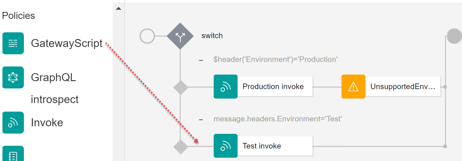
Figure 4.45 – Add the PID validation check
- You can use the code downloaded from GitHub called pidcheck.js to copy and paste in the code block of your GatewayScript policy.

Figure 4.46 – Applying error handling to GatewayScript
Review the following code. You will see that it checks for the length of the patient-id parameter value and throws an error based on the length of the patient-id value:
var patientid =
context.get('request.parameters.patient-
id.values[0]');
if (patientid.length < 36) {
context.reject('ValidateError', 'Incorrect
patient-id');
}
The code uses the context.get() method to access context variables. Parameters that you receive as part of the request are also considered context variables.
Inline Referencing and GatewayScript Referencing of Parameters/Variables
Techniques for accessing Parameters using Inline Referencing and Context variables are slightly different. Path, query, and header type Parameters can all be accessed using request.parameters.[parameter-name] using the Inline referencing technique. But to access Parameters in the GatewayScript Policy, you will need to use request.headers.[header-name] to access the header type Parameters or request.parameters.[parameter-name] to access the query/path type Parameters.
- Toggle the Show catches option. This will enable the Catches block. Click inside the Catches box to enable the Properties panel. Click Add catch.
You can build error-specific execution paths or a single execution path to handle multiple errors. Notice that the UnsupportedEnvironment exception that you recently created is in the list of errors to catch. This is shown in Figure 4.47:

Figure 4.47 – Throws you create are listed in available Catches
- Select UnsupportedEnvironment and ValidateError errors in Catch 0. You will be handling both these errors under a common Catch flow.
- Drag and drop a GatewayScript Policy on the Catch 0 execution path and name it Create Error Response. Copy the following code from GitHub, named errormsg.js, into this policy:
var errorName = context.get('error.name');
var errorMessage = context.get('error.message');
var errorResponse =
{
"name": errorName,
"message": errorMessage
};
context.message.header.set('Content-Type',
"application/json");
context.message.body.write(errorResponse);
The code demonstrates the method of accessing the error context variable in a GatewayScript policy. During the execution time, when an error is encountered, the error.name and error.message variables contain the name and the message of the thrown error. The other critical element to notice is the use of the message.header.set and message.body.write methods to set the Content-Type header and actual response, respectively. You can use the message.body.write method to create a message body for an invoke policy's request as well. Use of the message.body.write method is not limited to generating custom API responses.
Your screen should look like Figure 4.48:
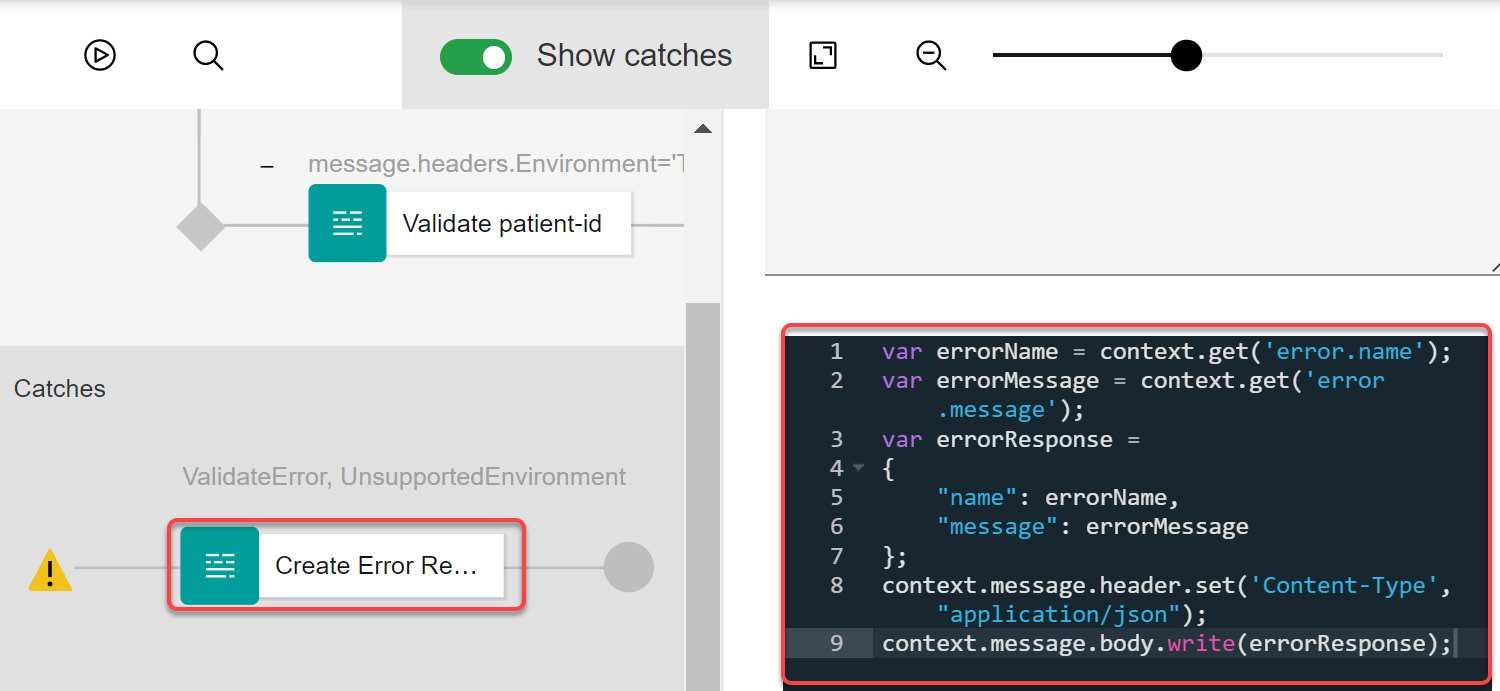
Figure 4.48 – Configuration of custom catch
- The final step is testing. As you have done in the past, click Save to save your API. Now click on the Test tab to test your new error features.
ValidateError testing: Add an Environment header and assign it a value, Test. Put in a random patient-id that is less than 36 characters and see how the API behaves. You should see the error message you configured in your error routine pidcheck.js.

Figure 4.49 – Incorrect patient-id
The error message will be presented as follows:
{"name":"ValidateError","message":"Incorrect patient-id"}
UnsupportedEnvironment testing: In your test case, substitute the value of the Environment header for Production. You will remember that in the Production branch of your API proxy, you used a Throw policy to throw the UnsupportedEnvironment exception. Click Send to send the request. What do you observe? You should see an error message like the following:
{"name":"UnsupportedEnvironment","message":"Set
'Environment' header to 'Test' because 'Production'
environment is currently unsupported."}
The preceding section demonstrated ways to handle API Proxy error conditions. You can build upon these examples to handle different error conditions, both custom and APIC runtime specific.
You have now built a solid foundation of various APIC development features. Soon you will discover many other rich features of the APIC framework, starting with its support for modernization patterns, building RESTful services using FHIR (a healthcare standard), API security, GraphQL, advanced transformations, and much more. This chapter was just the beginning of a rich journey that lies ahead of you. This chapter got you to "buckle up." Now is the time for you to "enjoy the ride."
Summary
You started this chapter by installing and configuring a local development (Designer) and a testing environment (LTE). After getting a brief introduction to the OpenAPI Specification (OAS), you put your local environment to good use by developing a simple API Proxy. This simple proxy creation exercise should have helped you get your feet wet and prepare you for a long swim in the pool of APIC.
This chapter then took you into a deep dive into the extensive development framework features provided by the APIC platform. You were introduced to many Policy types (Built-in and Custom) and Logic constructs, with a particular focus on the Invoke policy. With the introduction to variables, you learned about various context variables (request and message, especially) available to you for the fetching and manipulation of data flowing through the API. API properties and their usage in an Invoke Policy taught you methods for building environment-specific dynamic target URLs.
As you worked through many step-by-step examples, you were introduced to the vast capabilities of the Invoke policy. You covered the capabilities of applying blacklists and the setup of error handling for timeouts. You even learned how to execute more than one call to multiple backend service providers as part of the same flow. You were also briefly introduced to GatewayScript (as part of numerous examples) and the switch policy. The switch policy introduction contained examples for building switch conditions using scripts and variables. These capabilities will be highly beneficial to you as you begin building more APIs with varying use cases. There was an extensive repository of hands-on examples that covered essential topics of error handling, customizing an API's response, and advanced features of the Invoke Policy.
This chapter also explored multiple testing techniques available to you as a developer to test your APIs. Speaking of testing, you learned how to use the built-in test capability of APIC that includes the powerful feature of tracing. API Connect provides a one-stop shop experience by keeping development, testing, and tracing proxies in a single toolset – an ask of so many engineers!
You have seen just how quickly you can take an existing endpoint and create, promote, and test an API proxy. And with all the available features, Policies/Variables/Referencing, you as a developer can truly build robust, complex, and flexible APIs. But with great power comes great responsibility. The idea of API development is rooted in speed, agility, and simplicity. On your API development journey, if you observe yourself using all these features in developing a single API, it might be an opportunity to reflect on the design of that API itself. Food for thought!
With all this information and a solid base, you are now ready to take it up a notch and start with the modernization journey. The next chapter will teach you the techniques to expose hidden IT services to the outside world.