
Chapter 8
The Digital Video System
When you pick up a camera—whether it is your smartphone or a sophisticated high-resolution video camera—you are in fact inserting yourself into a history that spans almost 150 years. Today’s cameras, even high-definition (HD) video cameras, rely on the same basic principles that drove the earliest motion picture systems. As a professional media maker who seeks to be in control of the aesthetic possibilities of the medium you are working in, you will need to understand a complex array of specifications: frame rates, aspect ratios, resolutions, sampling, and data rates. Each of these has much to do with technological innovations that occurred at various points in the history of the film, and then the video, moving image. Understanding those principles is critical if you are going to make the best use of the technology available to you today, and tomorrow.
■ Film: A Mechanical and Chemical Medium
As early as the 1880s, people, especially scientists, were trying to find ways of reproducing motion so they could analyze natural phenomena around them. Forms of photography had existed since the 1830s, but the glass or metal plates, and the long time necessary to fix the image in silver halide crystals, made it unfeasible to capture subjects in motion. It was only in the 1890s that the Lumière brothers in France and Thomas Edison in the United States pioneered the first systems for capturing motion and playing it back for audiences.
Film is a mechanical and photochemical motion picture system. It creates the illusion of motion through the rapid presentation of a series of sequential photographic images fixed to a flexible and transparent strip of cellulose or acetate. A film camera gathers light from the outside world through its lens, and focuses that image onto the film to create exposures. A film projector pushes light from within the apparatus, through the images and through a lens, to focus and project that image onto a screen.
The early films were recorded and played back at a frame rate of about 16 frames per second (fps), resulting in the flicker effect we associate with early motion pictures. Eventually a frame rate of 24 fps became standard. Each frame is projected onto a screen and held stationary long enough for the viewer to register the image before it is quickly replaced with the subsequent still image, which is again held for a fraction of a second, and so on. The viewer perceives this rapid presentation of still images as motion through the perceptual phenomenon known as short-range apparent motion.1 Simply put, when shown a rapidly changing series of sequential still images in which there is only a slight difference from image to image, humans process this visual stimulus with the same perceptual mechanism used in the visual processing of real motion. This mechanism transforms the series of still images into motion through the psycho logical and physiological interpolation of information between the still frames. This “magic” is what creates the possibility of recording and playing back motion in film and video (Figure 8.1).

■ Figure 8.1 A 35mm filmstrip of the Edison production Butterfly Dance (ca. 1894–95).
From the film medium’s earliest days, directors used it to create non-fiction stories. As discussed in Chapter 2, the Lumière brothers used film to record early scenes of real life, called “actualities.” Robert Flaherty’s Nanook of the North (1922), about the life of an Inuit family in Northern Canada, is often considered the first “documentary”. Others, including John Grierson’s team at the Empire Marketing Board in the United Kingdom, used film to create monumental works about British workers and industry, including Drifters (1929), about herring fishermen, and Song of Ceylon (1935), about the colonial tea trade. These films relied heavily on visual storytelling and narration, as the technology for port able sync sound did not yet exist. During the late 1950s, Robert Drew and Ricky Leacock pioneered the use of a crystal-sync motor that would allow sound and picture recorded separately to be synchronized in postproduction. This was a major development for documentary, as filmmakers were free to shoot in places that had not been documented before, and could record people talking in the field on truly portable equipment. As Erik Barnouw wrote in his seminal history of documentary, “Field footage began to talk.”2 An early example of these new direct cinema films was Drew’s Primary (1960), which caught the drama of a political campaign featuring candidate John F. Kennedy with an immediacy audiences had not seen before. Over the entire history of film, including documentary, technological advances were driven by filmmakers trying to do things that had never been done before. As new equipment opened up new possibilities, the form itself changed.
■ Video: An Electronic Medium
While film cameras and cinematography emerged from the world of still photography, the ancestor of modern video technology is radio. As early as the 1920s, scientists were working on the developments that would lead to television and modern video. The biggest issue facing them was how to take a two-dimensional electronic image and turn it into a continuous signal so that it could be transmitted or broadcast. The answer developed by scientists, such as John Baird in Scotland and Vladimir Zworikin in the United States, was to “scan” the image, breaking it down into a series of lines of picture information that could be fed over a wire to a transmitter as a continuous electronic signal. The first scanners were mechanical, but scientists quickly realized that they could control a beam of negatively charged electrons using a ring of magnets to “paint” a picture on the end of a cathode ray tube (Figure 8.2). This scanning process is still at the heart of video image capture and reproduction today.
■ Figure 8.2 The cathode ray tube emits a beam of high energy electrons, which hit the end of the tube painted with phosphors, causing it to glow momentarily.
By the late 1930s, the United Kingdom, Germany, and the United States had video transmission systems that could capture picture and sound in one location and send it almost instantaneously over fairly long distances. During the early years of television, electronic recording devices did not exist. The only way to record those images was to film them from a television screen. TV remained basically a “live” medium until the development of a viable recorder and videotape by the Ampex Corporation in 1956. The early recorders were expensive and bulky, making them appropriate only for network television use.
The late 1960s were a watershed moment for documentary. In 1967, the Sony Corporation developed inexpensive portable video recording equipment that offered, finally, a real alternative to film (Figure 8.3, top left). One of the biggest attractions was the possibility of shooting for extended periods of time on a very inexpensive medium, magnetic tape. A black-and-white camera and a microphone were connected by cables to a battery-operated open reel video tape recorder. At first the output was not considered broadcast quality, but the airing of Susan and Alan Raymond’s Emmy-award winning The Police Tapes on ABC in 1977 meant that portable video was here to stay (Figure 8.4). In addition, the video equipment was simple to operate in difficult circumstances and much more light-sensitive than film, allowing for night shooting with only street lighting as illumination, giving viewers access to a world that had never before been shown on screen.
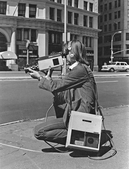
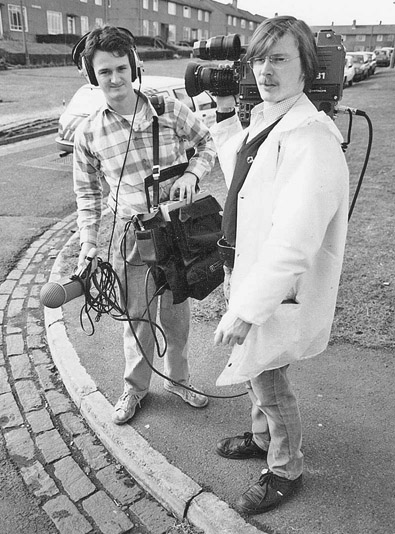

■ Figure 8.3 Edin Velez, an early video “pioneer,” with a Sony Portapak (top left). On the top right are Philip Johnston and Ian Bodie with a typical 1980s video equipment package: a U-matic camera and separate recording deck. The development of the CCD sensor allowed for the consolidation of camera and recorder in the form of the camcorder in the 1980s (bottom), pictured is cinematographer Gary Griffin shooting Prudence Hill’s Three Women (1995) in Bangladesh.
In the early 1970s, Sony developed a color video cassette recorder for more professional use. It used a 3/4” tape format, called U-matic, and the deck still had to be connected to the camera with a cable and carried separately, often by the sound recordist (Figure 8.3, top right).

■ Figure 8.4 The Police Tapes, for which Susan and Alan Raymond spent three months filming police in the South Bronx, opened new ground for documentary by using simple black-and-white portable equipment designed for amateur use.
In the 1980s, the camera and the video tape recorder were married into one unit, and the modern camcorder was born (Figure 8.3, bottom). This development was very important for documentary as it allowed a single individual to record both sound and image. Over the years, development of smaller and smaller tape formats such as Hi-8 and MiniDV consolidated this trend, making unobtrusive cameras and a truly personal approach to documentary possible.
Analog vs Digital Video
For most of its history, video was an analog medium. This meant that the light and color of the image corresponded to the strength and frequency of its analogous electronic signal. At the turn of the twenty-first century, the “digital revolution” transformed media production. Digital media involves creating, recording, and disseminating video and audio by transforming light and sound values into binary code, or a series of ones and zeros. There are numerous advantages to digital media, including superior resolution, greater flexibility for creative manipulation, and the ability to make copies with no generational loss. Importantly, the advent of digital media meant not only better quality imagery, but material that could be edited on a computer, transforming the workflow for documentary film makers. More recently, the advent of digital video precipitated another revolution by delivering HD video formats in addition to the standard-definition (SD) formats that were previously available. In this book, the term “digital video” encompasses both SD and HD formats. We will explain what these different formats mean in detail later in this chapter.
The Video Image Today
While the film system has remained virtually unchanged in well over 100 years, video technology seems to be in a perpetual state of rapid evolution. New video cameras and formats are introduced almost yearly, and swift technological obsolescence is the rule rather than the exception. Unfortunately, the world of video engineers, corporations, and government committees have not managed to coordinate their efforts to establish a single national video standard, let alone a worldwide standard. With enormous profits on the line, corporate rivals and nations continually race to develop their own superior systems in the hope that theirs will become the new standard. Current count reveals dozens of major digital video formats, making the world of video production seem like a technological tar pit for emerging filmmakers and veterans alike. Most filmmakers deal with these issues when confronted with having to make choices among the bewildering variety of cameras available. Before we launch into a discussion of camera choices, though, it is important to consider the complex world of digital video formats. In video, format can mean a number of things, and these fall into four broad categories.
Recording Formats
Recording Formats (also called acquisition formats) determine the way a particular system, like a camera, encodes and records video. Current examples include AVCHD, XAVC, HDV, and MXF. Older tape-based examples include DVC-Pro, DVCam, and miniDV. Recording formats have unique technical specifications including resolution, aspect ratio, data rate, and encoding system.
Media Formats
The physical medium on which video data is recorded is often referred to as its media format. Historically most video formats were tape-based, but these have largely been replaced by file-based media formats that record on various forms of solid-state memory. Examples of popular media formats today include P2, SDHC/SDXL, CF, and SxS cards (pp. 122–124). Most of these media are capable of handling many different recording formats.
Display Formats
Display formats are a set of specifications for how video is broadcast, received, and displayed. In the United States, they are codified in a set of nationally mandated digital television broadcast standards devised by the Advanced Television Systems Committee(ATSC). Examples include 1080i and 720p (both HD formats) and 640 x 480 (an older, SD format). In addition, there are a variety of formats used for Internet streaming on services like Vimeo and YouTube, which are not subject to regulation. Digital Cinema has separate sets of format specifications, established by film studios under the Digital Cinema Initiative (DCI), which specifically address digital theatrical projection.
Audio/Video Codecs
A codec (short for “compression/decompression”) is a way of reducing digital file size to make the large amounts of information generated by digital media production easier to store and transmit. These are not technically formats, but they are so integral to the process of working with, within, and across formats (in recording, editing, and distribution) that a filmmaker must be able to identify them and understand their function. The most commonly used codecs are those approved by the Motion Picture Experts Group including MPEG-2, MPEG-4, and H.264. Related to codec is data rate, which is explained in detail below.
In the United States and globally, there are a wide variety of acquisition, media, and display formats, as well as dozens of audio and video codecs. They are constantly evolving, and it would be folly to try to cover them all in detail. But in the world of digital video, knowing some technical information is imperative in order to make informed creative choices and to develop a smooth creative and technical process from preproduction to distribution. It is worth noting that while there are a huge variety of options in terms of format, all of these must fall into a set of specific categories that define image size, frame rate, and other key aspects of the video signal so that we can record material that viewers can watch, whether on a television, a computer, or a digital theater projector.
Broadcast Standards
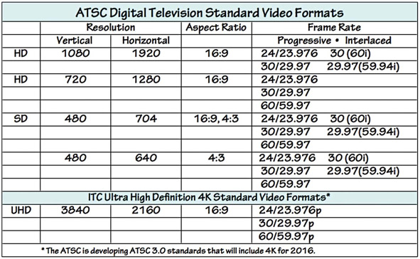
■ Figure 8.5 The ATSC standards for recording and exhibiting video were last revised in 2006. The new standards, including for Ultra High Definition (4K), are due out in 2016. The International Telecommunication Commission’s standards for 4K broadcast are included here as they are currently available on many 4K cameras.
In the United States, video standards are defined by the ATSC and are summarized in Figure 8.5. The ATSC, like the National Television System Committee (NTSC) before them, is a consortium of engineers, telecommunications companies, and government policy makers who are responsible for setting video standards. These standards ensure compatibility between digital image recording and display systems across all nations that adopt the standard (these include the United States, Mexico, Canada, and other countries in Central America, the Caribbean, and the Asia Pacific region). The analogous standards consortium in Europe is the European Broadcast Union (EBU). The International Telecommunications Union (ITU), a specialized agency of the United Nations responsible for issues that concern information and communication technologies, is also involved in defining standards globally. There are a variety of features that these standards define, including image resolution, scanning type, and frame rate.
Figure 8.5 lists the 17 digital video format standards supported by the ATSC broadcast system. Seven of these are HD formats and the rest are SD. Remember, the standards are not just for broadcast display, but for the capturing of images as well, and are reflected in the options available on your video camera.
Resolution
Whenever there is an evaluation of video image quality, you will hear the term resolution. Resolution generally refers to the ability to reproduce visual detail: sharpness of line, subtlety and degrees of luminance, as well as the accuracy of color. Video resolution is affected by a bewildering and complex array of factors. These include the format scanning system (progressive or interlaced), lens quality, the quality of the camera’s electronics, the number of pixels in the sensor, sampling bit rates, chroma subsampling, and data compression (all explained later). To a great extent, though, resolution is a function of the number of pixels that make up the image (Figure 8.6). We can determine the pixel resolution of a given format by multiplying the vertical lines by the horizontal pixels. Standard-definition digital video (704 · 480, for example) contains a little more than 338,000 pixels with which to define the image. High-definition video, with a resolution 1920 · 1080, provides for 2,073,600 pixels per frame. With this greater resolution capacity offering more detailed visual information to the eye, it is no surprise that HD looks crisper and more vivid.
Occasionally, you will see or hear reference to 720p HD. This is an older HD format that you will find as an option on many cameras. One might wonder why anyone would use 720p HD, which has only half the pixel count of regular HD. This is where scanning frame rates enter into the resolution question. 1080i has twice as many total pixels, but the fact that it is an interlaced signal (p. 113) means that it creates a frame by making two fields, each lasting for a 1/60th second. Each field contains only half those lines (540). So in the final calculation, 720p, with its progressively scanned full image in each frame, delivers somewhere around 56 million pixels per second, while 1080i utilizes around 62 million pixels per second. This means that 720p only offers slightly less resolution in the image than 1080i.
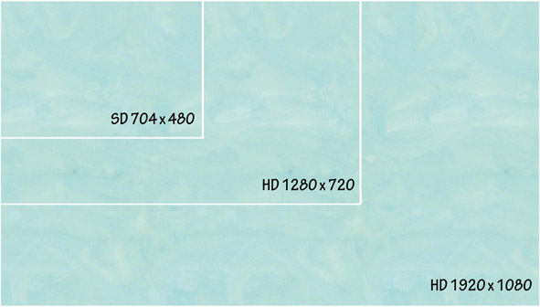
■ Figure 8.6 The resolution of video formats can be roughly determined by multiplying the horizontal by the vertical pixels. This illustration shows the relative resolution capabilities based on pixel count.
It is important to understand that HD is a complete system of image creation and exhibition. To realize the improved resolution of HD, you not only need to shoot on HD but you also must master your final project on an HD format and display that image on an HD-capable monitor or projector. Shooting HD, but displaying the footage on an SD monitor, will reduce the quality of your original image to—you guessed it—480 lines of vertical resolution. Conversely, if your footage originated in an SD format, displaying it on an HD monitor will not increase the resolution quality.
Aspect Ratio
SD and HD have different aspect ratios. SD video has an aspect ratio of 4:3, of 1.33:1, while HD has an aspect ratio of 16 x 9 (or 1.78:1), making it closer to the widescreen film aspect ratio (1.85:1) familiar to theater-going audiences. See Chapter 7 for more on aspect ratios.
Scanning Type
As we discussed, digital video records and plays back images using an electronic process known as scanning, which analyzes the image line by line and outputs it for recording. As you can see in Figure 8.5, starting in the days of SD analog video, the video frame was split into a series of horizontal lines allowing it to be processed as a continuous stream of signal information. In the United States, there were 525 lines of picture, in Europe 625, and there were variations in other countries. Digital video offers two different methods for scanning a full frame of video: interlaced (i) and progressive (p) as well as different frame rates.
Interlaced Scanning
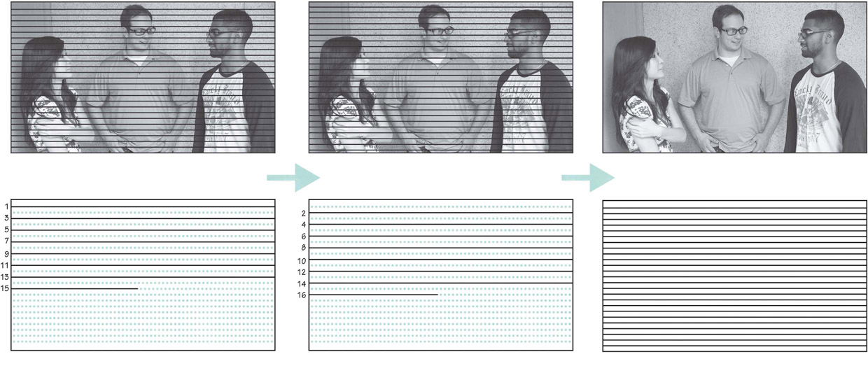
■ Figure 8.7 Interlaced video. First, the odd lines are scanned, from top to bottom, then the even lines are scanned, creating the second field. The result is a full image.
In the case of interlaced scanning, the camera’s imaging device first outputs the odd-numbered horizontal pixel lines (1, 3, 5, 7, etc.), one at a time, from the top to the bottom, creating a half-resolution image that is called a field of video. Then, the imaging device returns to the top of the frame to output the even-numbered rows (2, 4, 6, etc.), from the top to the bottom, to fill in the rest of the information with a second field. These two fields of video are interlaced to make up one full frame (Figure 8.7). All this electronic information is then converted into digital data for storage on the recording media. During playback, the monitor or receiver duplicates the exact same interlaced process, line for line, field for field, and frame for frame, in perfect synchronization with the scanning used to record the image. The digital information is converted back into electrical voltage, which is then translated into light values (an image) as the electrical voltage causes the horizontal rows of pixels in a monitor to glow. In a plasma display, these pixels are colored fluorescent cells, in an LCD monitor they are tiny LCD crystals, and in an LED monitor they are tiny LED lights. Interlaced scanning was developed as the standard scanning method for the original analog video systems because it refreshes the image more frequently to reduce flicker in the image.
When you see the scanning rate of 60i (“i” for interlaced) in the ATSC table in Figure 8.5, it means 60 fields of video information interlaced per second, for a frame rate of 30 fps. In other words, each field contains half the picture information, and lasts half as long as the full frame. Interlaced scanning has remained in the ATSC standards to ensure backward compatibility and as a way to deliver high-quality content at reduced signal bandwidth.
Progressive Scanning
Progressive scanning differs from interlaced scanning in that one frame is not made up of two interlaced fields (odd lines first, then even lines). Instead, with progressive scanning both the sensor and display are synchronized to scan a full frame of video (lines 1, 2, 3, 4, etc.) from top to bottom in a continuous line, like a farmer ploughing a field. There are no fields, just complete frames (Figure 8.8). Progressive scanning frame rates are written as 24p, 30p, and 60p (“p” for progressive). Although progressive scanning requires more processing power and bandwidth than interlaced video at the same frame rate, many cinematographers prefer its “filmic” look (see “In Practice: 24p or 60i?” on the next page).
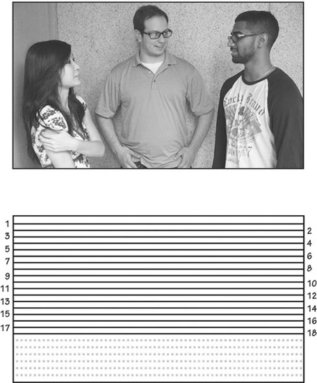
■ Figure 8.8 Progressive scanning draws a full frame of video, from top to bottom, without skipping any lines.
One serious problem occurs when you try to view an interlaced image on a progressive scan display (including computer monitors). The process of the progressive scanning pattern will present the two interlaced fields as slightly offset, which is especially noticeable with objects in motion (or during camera movements). The resulting image will have a combing artifact along edges in the image (Figure 8.9). To avoid this, the interlaced scanned video should undergo a process known as “de-inter lacing” before it is displayed on progressive scan monitors.

■ Figure 8.9 When interlaced video is shown on progressive displays, a “combing” artifact occurs at the edges of moving objects caused by the displaced scan lines (notice that the stationary objects do not show any combing).
Frame Rate
Frame rate refers to the number of still frames that are captured by a camera, or played back on a viewing system, over a specific period of time (usually 1 second). Digital video systems in North America run at a frame rate of 30 fps. In many parts of the world, including Europe, 25 fps is the standard. In the ATSC Video Format Standards table (Figure 8.5), you’ll notice that there are whole number frame rates supported, like 30, 60, and 24. However, there are also frame rates listed that are ever so slightly slower than their whole number counterparts, namely 59.94, 29.97, and 23.976. These slowed-down frame rates (0.1 percent slower) are legacies of the old NTSC system, which remain with us in order for new equipment to stay compatible with SD format standards (which were derived from the NTSC system).
■ 24P or 60I?
Deciding whether to use a progressive or interlaced scanning mode is a complex question. While interlaced (60i) might seem like the obvious choice for anything headed for broadcast, some filmmakers find there is an aesthetic advantage to shooting 24p. (In many parts of the world, the choice is between 50i and 25p.) While it is hard to quantify the difference, the consensus suggests the way that 24p handles motion is more “filmlike” even for a project that will be shown in a broadcast context. On the other hand, if you want to capture the details of motion, as with sports, you may prefer the 60i rendition. Remember that many other factors, such as the size of the image sensor and the type of lens, are also part of the “look.” Here are some documentary cinematographers on this topic:
S. Leo Chiang: I mostly shoot on 24p. I just like the look of it. Most of the people I know shoot on 24p for their indie projects, although most freelance gigs with broadcasters I’ve done have been 60i. 60i feels more cold and traditionally “video like.” 24p feels more “film like,” more cinematic.3
David Alvarado: I shoot exclusively on 24p, but just for the look of it. If you want something to look cinematic and fluid, shoot 24p on 48 shutter speed. If you want it to look like television video, go for 60i or 30p. I think it’s just a preference, so there’s no right and wrong. Do a side by side comparison for yourself and see what you like most.4
Vincent Laforet: Film is just as much about what you DON’T show the audience as with what you DO. Motion blur, lack of sharpness, and movement all help to create movie magic. If images are too sharp and you see too much detail . . . that’s not always a good thing.5
Todd Grossman: The creative choice between 24p and 60i can be a very subjective one. Whereas most high-end HD filmmakers will shoot 24p for the purpose of getting that film look, a lot of documentary and action-sports cameramen prefer 60i for the exact reason that others dislike it: the sharpness, clarity, and deep-focus ability are great for capturing the action.6
Before the advent of color TV, the original NTSC black-and-white video signal was a nice and neat 30 fps. In the early 1950s, the NTSC developed the standards for color television and in an effort to make color television compatible with all preexisting monochrome receivers, the NTSC superimposed the color component on top of the existing black-and-white signal along a subcarrier frequency (3.58 MHz) rather than create a whole new, fully integrated signal. This ensured that even though a program was broadcast in color, viewers who owned black-and-white TV sets could still see it. However, this created interference between the two signals, and required that the frame rate be altered. The 30 fps signal (60 fields per second) became 29.97 fps (59.94 fields per second). Therefore, when we are talking about video production, the rate 60i (perhaps the most widely used) is actually 59.94 fields per second (29.97 fps). The 24p frame rate is actually 23.976. Most video cameras in fact shoot in these slowed-down frame rates, even if the frame rate options menu lists the rounded numbers.
While there are other options, filmmakers today will likely choose between shooting at a frame rate of 60i or 24p.The 24p frame (24 fps, progressive) was developed specifically to be compatible with, and to duplicate, the look of motion picture film, which runs at a frame rate of 24 fps. 24p video replicates some of the motion artifacts of film, giving it a so-called “film look” even when played back on 60i video monitors. Some people really like the 24p look, while others are not as convinced (see “In Practice: 24p or 60i?” above). If you are shooting 24p and planning to distribute on DVD or go to broadcast, you will need to convert to 30 fps through a pulldown process, so it’s important to think through all stages of your project from production to distribution. This very common transfer process from a 24 fps system to a 30 fps system is explained in detail in Chapter 17.
■ Time Code
Regardless of the frame rate, every frame of a video recording is assigned a specific and unique number called time code (TC). Recorded right along with the video data for each and every frame is an electronic number with four sets of digits: hours, minutes, seconds, and frames. This numbering system is vital to the workflow of every video project. We use TC to quickly log, reference, or locate specific frames, to calculate the length of shots, scenes, and entire projects, to maintain audio and video synchronization, and to ensure frame-accurate edits. In short, TC, along with clip names, is the way we keep track of the frame-by-frame timing of every element, at every stage of a project. Virtually all video cameras have TC, although not all cameras allow you to set it to a number you want. Many offer a choice of two different flavors: drop-frame time code (DF TC) and non-drop-frame time code (NDF TC) (Figure 8.10). Why do we have two ways to count frames? Remember that in the early days of color television, it was found that the 30 fps signal produced interference between the sound and the color parts of the signal. The answer was to slow down the frame rate slightly (0.1 percent) from 30 fps to 29.97 fps.

■ Figure 8.10 Time code assigns a specific number to every video frame according to a format that indicates hours, minutes, seconds, and frames. Broadcast video uses only “drop frame” time code, easily identified by its use of semicolons (B), because it is time accurate. Some applications still provide the option to use “non-drop-frame” time code, which uses colons as separators (A).
Non-Drop-Frame Time Code (NDF TC) simply counts frames according to the original black-and-white video frame rate, assigning a new number to each video frame at a consistent rate of 30 fps. This seems simple, but it doesn’t match real time and is rarely used. What looks like an hour of video in NDF TC is actually 1 hour and 3.6 seconds. That may not seem like such a big deal, but in broadcast television, where programs and commercials must conform to frame-accurate timing, it is crucial to have precise measurements.
Drop-Frame Time Code (DF TC) does not actually drop any video frames, but it does skip over some TC numbers from time to time in order to adjust the frame count to accurately reflect the true 29.97 fps of NTSC video. To be precise, the DF TC system skips over the :00 and :01 frame numbers once every minute, except for the 10th minute. Here is how the TC numbers change at each minute of footage (except for every 10th minute): 00;09;26;28, 00;09;26;29, 00;09;27;02, 00;09;27;03. After an hour of DF TC counting, we will arrive at TC 01;00;00;00 for exactly 1 hour of video footage. Most cameras will default to DF TC as this gives you a more accurate idea of your timing, and is what broadcasters require.
■ Types of Digital Video Cameras
Historically, video cameras fell into fairly neat categories. Professional cameras were big, expensive, well made, and produced high-quality video. Consumer cameras were small, inexpensive, had an inferior image, but were easy to use. Today, small affordable cameras are delivering extremely high-quality images, so much so that professionals use them extensively. While consumer-level equipment tends to be fully automatic, many mid-level cameras offer control over basic and even more advanced functions that filmmakers can use to achieve sophisticated effects. For example the Canon XF300, at US $4,000, offers manual control over focus, aperture, frame rate, white balance, and data rate as well as professional audio inputs. These high-quality yet affordable video cameras may be too complex for the average consumer, but they are excellent when a polished and controlled look is important and a high-end, professional rig would be too big or expensive. In this book, we will focus on this mid-level range, and on some other cameras that are commonly used by independent filmmakers and students. There will always be trade-offs between cost and quality, but much of your decision about what camera to use will also be based on the particulars of your shooting situation and desired style.
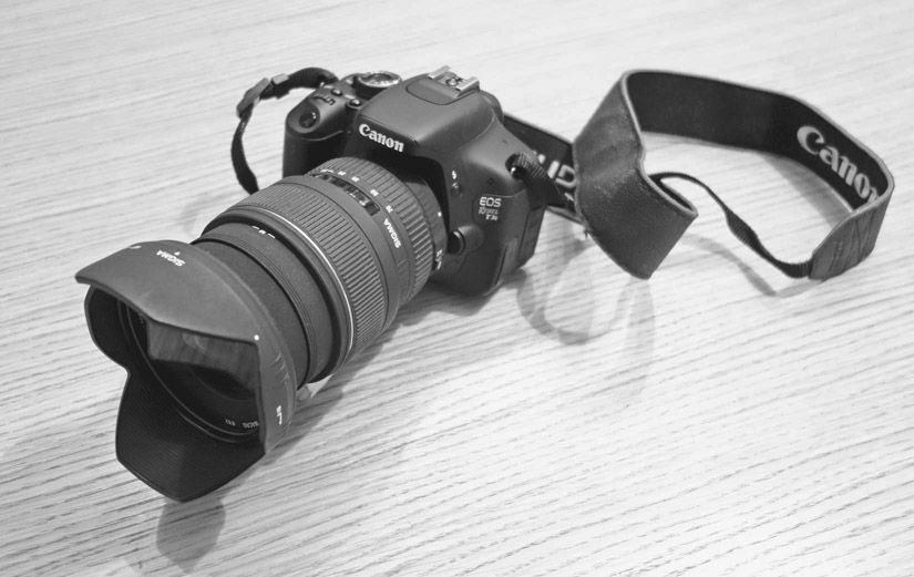
■ Figure 8.11 DSLR cameras, such as this Canon T3i, are often used for documentary shooting.
One of the most important developments in documentary cinematography over the last decade has been the emergence of the digital single-lens reflex (DSLR) camera as a filmmaking tool. While the ability to shoot moving images with what was formerly a still camera was a feature intended for the consumer market, filmmakers seized on DSLRs and used them to create a new look in both documentary and narrative filmmaking. High-end DSLR cameras (like Canon’s EOS series or Nikon’s D series; see Figure 8.11) are designed with a large complementary metal oxide semiconductor (CMOS) sensor (see pp. 126–127), which takes high-resolution images, notably superior to those from previous generations of video cameras. In “movie-mode,” the single CMOS sensor can capture and record 1920 · 1080 images at 24, 25, and 30 fps.
A number of factors have made DSLR cinematography a very popular video production format: (1) an increase in SD and CF card storage capacity, and a drop in their price; (2) the fact that you can use an entire range of high-quality interchangeable lenses; (3) the large sensor and “big glass” make these cameras highly light sensitive, increasing control over depth of field (Chapter 9); (4) a substantially lower cost; and (5) the lightweight and compact body size, which can be helpful in situations where a large camera might impede intimacy (Figure 8.12).


■ Figure 8.12 Bully (2011), a documentary directed and shot by Lee Hirsch, takes advantage of the shallow depth of field (top) and intimacy (bottom) afforded by DSLR cameras.
There are downsides to DSLR video shooting. The shape and size of a DSLR camera, while perfect for still photography, is awkward for creating smooth camera moves and adjusting focal length and focus while shooting handheld, so most users will find that some sort of stabilizing rig is useful when shooting without a tripod (Chapter 10). Often these rigs can be more expensive than the camera itself. Another very important drawback for small crews is the fact that these cameras are poorly set up for audio recording, as they lack the XLR inputs that make single system shooting workable (Chapter 13). This means that in the field the filmmaker is dependent either on working double-system, with a separate sound recordist, or working with a rig that includes a microphone mount and bringing the audio in through a miniplug, which is an unstable connection and prone to interference. Another problem with single system sound is that in DSLRs, sound controls are often menu-based and therefore cumbersome to access, especially while shooting. Even with a shoulder mount (Chapter 10), the DSLR presents specific problems for observational shooting. Zoom lenses on DSLRs have less range (3:1 vs the 10:1 or 20:1 on a video camera) and the zoom has to be controlled manually instead of being motorized as on a video camera. In addition, the shallow depth of field gives a filmic look, but means that maintaining focus on a moving subject will be difficult. The autofocus capability of these cameras, while improving, is still not typically on par with that of camcorders. Finally, these cameras are designed for still photography, so shooting hours of moving footage can trigger overheating problems, which may result in camera shutdown. Despite these limitations, though, documentary filmmakers are making great use of DSLRs.
If you are planning to use this highly affordable camera type, you should be aware that there are two main groups of formats, based on sensor size. One, called APS-C, is loosely based on an older film format and measures 22mm x 15mm. The second is called full 35mm and is about 35mm x 24mm. Although they will both offer excellent results in terms of image detail and the ability to create shallow depth of field, the larger sensor generally offers superior image resolution and light handling capabilities.
Hybrid Large Sensor Cameras
One solution to the problems of the DSLR has been the hybrid large sensor camera, which attempts to bridge the gap between the ease of use of video cameras and the large sensors and interchangeable lenses of DSLRs. Like most compromises, these vary greatly in quality. One manufacturer, Canon, has attracted many users in the documentary field with its relatively inexpensive EOS C100 camera (Figure 8.13). This unit can be handheld and manually controlled, uses the popular Canon EOS lenses, and features XLR audio inputs for professional audio.
In the POV 2013 Documentary Filmmaking Equipment Survey,7 the single-most used camera by documentary filmmakers was the Canon C300, indicating that this type of hybrid camera has already secured a primary place in the market. The C100, a less expensive version of the same camera, was close behind. While the survey hasn’t been updated, anecdotal evidence suggests that this type of camera has only gained popularity among documentary filmmakers.
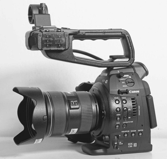
■ Figure 8.13 The Canon EOS C100 is a good example of a hybrid camera that combines the large sensor and interchangeable lenses of the DSLR with some of the advantages of a video camera body.
Mirrorless Shutter Cameras
DSLRs have a drop-down mirror that allows for through-the-lens viewing when shooting stills, something that is unnecessary for filmmaking. Another group of cameras that has found popularity is the mirrorless shutter camera. These are cameras that have a small body reminiscent of amateur point-and-shoot still cameras, and they have no optical viewfinder. Lacking the drop-down mirror that DSLRs use for viewing, they can be notably smaller and lighter. If you want a lot of resolution in a very small package, this may be the way to go. For an example, see the Lumix GH4 in Figure 8.15.
Minicams
One type of camera that has proved particularly useful for documentary shooting is a group of very small cameras with tiny sensors, fixed wide-angle lenses, and no viewfinder. These extremely small lightweight cameras are inexpensive, record to miniSD cards, and can be mounted anywhere, from skateboards to small aerial drones.
One recent documentary that made use of minicams to create a new visual aesthetic was Leviathan (2012), by Lucien Castaing-Taylor and Véréna Paravel (Figure 8.14). Their film uses tiny GoPro cameras to explore the sensation of being a fisherman (and a fish!) at sea. Paravel says:
Maybe because we attached those cameras to the fishermen themselves the result is an embodiment of this very cephalic point of view. It’s not only the body that’s moving, you’re literally in their head, you’re with them, you’re a part of their actions, but your spatial and temporal orientation disappears and this is how you feel on a fishing vessel. So, we wanted to privilege this unique perspective, but we didn’t want to limit it to the fishermen. Unlike in most documentaries where it’s only the human subjects’ perspective, we wanted to give the same ontological weight to the fishermen and their catch and it spread to the elements as well.8

■ Figure 8.14 Leviathan was shot mainly with small GoPro cameras whose wide-angle lens and ability to function under adverse conditions help give this film a look that critics have called “hallucinatory.”
The Ultra High End: 4K and More
As mentioned above, a 4K image format (exactly four times the size of an HD image) is available and cameras are being developed to take advantage of it. The format was originally developed for digital cinema cameras designed to shoot feature films, but several levels of camera are now available. A small camera offering 4K is the Lumix GH4, which can be held in the palm of a hand and is compatible with a documentary workflow (Figure 8.15, right). At the high end for documentary production is the SONY XDCAM PXW-FS7 (Figure 8.15, left), which offers good ergonomics for location observational shooting (including a servo zoom control and the ability to be mounted on the operator’s shoulder), a lens mount that allows many types of lenses (using adaptors), and Ultra High Definition (UHD) recording.
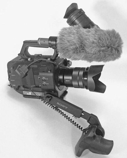
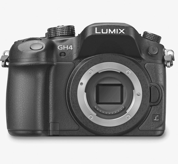
■ Figure 8.15 The Sony PSW FS-7 (left) and the Lumix GH4 (right) offer a 4K image in two different handheld formats.
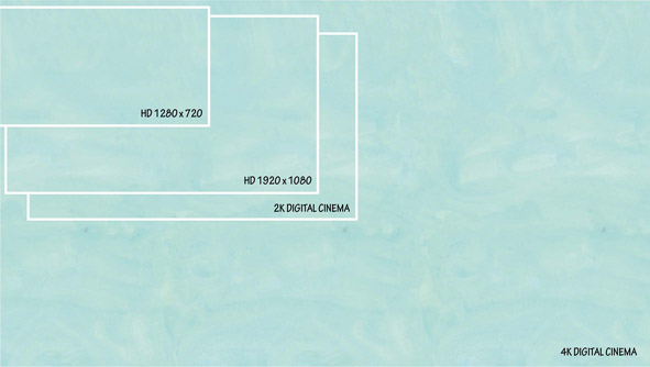
■ Figure 8.16 Comparison of the relative resolution capabilities between 720 HD, 1080 HD, 2K, and 4K formats based on pixel count.
As with HD, there are several 4K format options including UHD (3840 x 2160) and DCI (4096 x 2160). Other available formats are 2K (2048 x 1080) and 2.5K (2560 x 1600 or 2560 x 1440) (Figure 8.16).
Another key area for makers interested in a higher quality image is the bit depth of the recorded signal (for more on bit depth, see pp. 129–130). Some professional video cameras record at various bit depths, typically 8-bit or 10-bit. Others, like the Sony PSW-FS7 (Figure 8.15, left), can record 8- or 10-bit internally or in 12-bit RAW uncompressed if you use an external, rear-mounted recorder. Other cameras allow you to bypass their image compression by sending the uncompressed signal out via the SDI/HD-SDI or HDMI output to a high-capacity hard drive.
So what’s all that resolution for? These ultra-large resolutions do not conform to the ATSC standards because they’re not intended for HDTV broadcast; they were developed for large screen theatrical projection. Broadcasters, led by NHK in Japan, are currently developing broadcast channels for the UHD format. Currently documentarians shoot 4K because it allows for cropping your image, as well as very high-end color correction, and you can “future proof” your work by creating a piece in a format that is likely to become standard in the near future.
The Basic Video Camcorder: Exterior
The standard camera design for documentary is the camcorder. While the name “camcorder” was originally given to video cameras that recorded image and sound together, the term is more commonly used now to differentiate video cameras from DSLRs. Most camcorders contain the same basic components and essential functions (Figure 8.17). As might be expected, the hybrid large-sensor cameras lack some of these functions, notably a motorized zoom lens, but share most other characteristics. We are devoting some time exploring the camcorder because despite the rising popularity of the DSLR and other camera designs, the camcorder remains a solid choice for observational documentary shooting on location.
The Body
The camcorder records single-system, which means that the body contains all of the electronic circuitry to gather and record both audio and video. Generally there are two types of camcorder bodies: shoulder-mounted cameras and smaller camcorders designed to be held in the operator’s hands. Shoulder-mounted camcorders tend to be found on the high-end professional range, where cameras are heavier and larger. A shoulder-mounted camera allows for very stable handheld shots, while smaller cameras are more difficult to keep steady without a tripod or stabilizing rig (Chapter 10). Many filmmakers find that the unobtrusiveness and mobility of a smaller camcorder allow for a greater sense of intimacy and spontaneity. One type of camcorder body is not inherently better than the other, but the difference in size and weight does have an impact on what you are able to do with the camera and so should be considered in tandem with your visual approach.
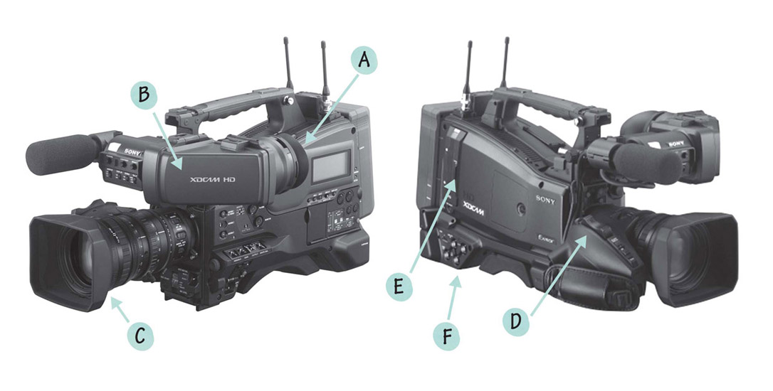
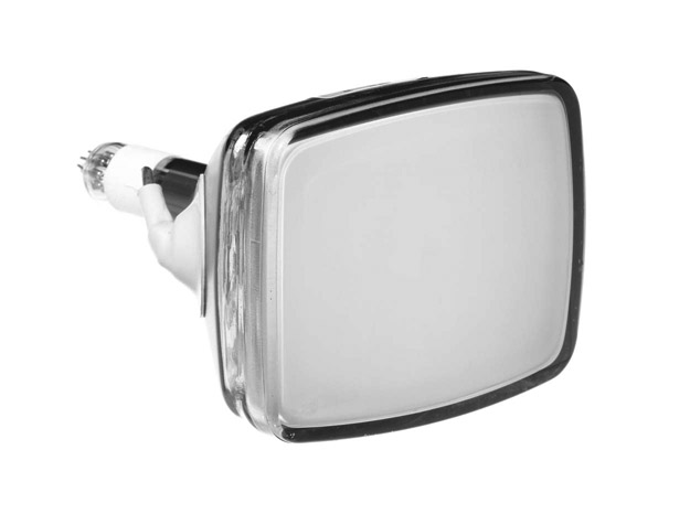
■ Figure 8.17 Prosumer and professional video cameras have the following features: a viewfinder (A), an LCD viewscreen (B), a lens (C), a servo zoom control (D), a record media bay (E), external microphone inputs (not visible), and audio/video inputs and outputs (F). Pictured is the professional (and expensive) Sony PMW-400K.
Viewfinders and LCD Viewscreens
Video camcorders have electronic viewfinders that allow you a glare-free look at the video image through an eyepiece that fits tightly against the camera operator’s eye. This is extremely helpful for shooting in bright situations, when an LCD viewscreen (see below) is hard to see. The eyepiece contains a diopter viewer, or magnifying lens, that can be set for the camera operator’s eye. This means an operator who normally uses glasses may be able to shoot without them.
Most camcorders also have an LCD viewscreen that flips or slides out to monitor your video. These screens are not as accurate as the viewfinder because changes in the viewing angle seriously alter the color and brightness of the image, as does the amount of glare the LCD screen catches from the ambient light. When shooting outdoors, an LCD monitor hood is essential for keeping sun glare from washing out the screen (Figure 8.18). Viewscreens are invaluable as a composition aid when you want to shoot from angles or create camera moves that make using the viewfinder difficult.
The Lens
The function of the lens is to gather the light reflecting off your scene and focus it onto the image sensor. Everything visual goes through the lens, so quality is important. A poor-quality lens will give you a poor-quality image. Lens quality is a major factor that separates consumer camcorders from those intended for professional use. Luckily for us, the dramatic improvement of video imaging devices has been paralleled by an evolution in the optical quality of lenses.
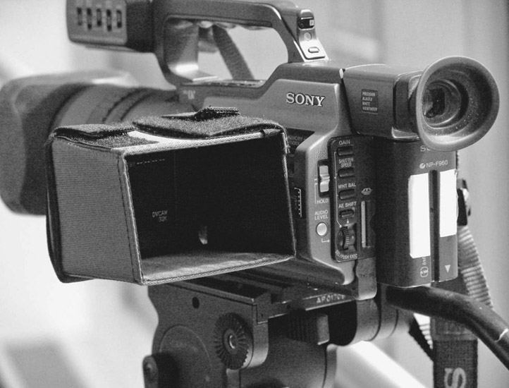
■ Figure 8.18 An LCD monitor hood keeps sunlight from washing out the LCD screen when shooting in sunny locations.
The majority of mid-level and professional camcorders come with a zoom lens, which means that the lens has a range of focal lengths (Chapter 9). The zoom range of any specific lens is expressed in its magnification ability. With a 10 · 1 (or 10:1 or “ten to one”) zoom lens, the degree of magnification increases 10 times over its full range. A 20x (or 20:1) zoom lens increases magnification by 20 times. The larger the magnification ratio, the greater the magnification power of the lens. Many cameras offer interchangeable lenses, so they can take advantage of a wide range of zoom and prime lenses. Cameras with fixed zoom lenses offer adaptors to extend the wide-angle or telephoto range of the lens. Consumer cameras under $1,000 generally come with a lens that is made of plastic or extremely low-quality glass elements. Plastic lenses are lighter and cheaper, but they are less sharp and often result in an image of lower resolution than the format is capable of producing.
The basic optical functions and compositional attributes of a lens are so important to the creative dimension of filmmaking that we have devoted an entire chapter specifically to this topic (Chapter 9).
Servo Zoom Control
Accompanying the zoom lens on most video cameras is the servo zoom mechanism, which enables you to glide through the zoom range, from wide-angle to telephoto and back, with the touch of a button (Figure 8.19). The servo zoom mechanism consists of a small motor operated by a rocker switch. Not all rocker switches are created equal, and this is another area that separates professional cameras from cheaper alternatives. A good-quality servo zoom is pressure sensitive. The harder you depress the mechanism, the faster the zoom, and the lighter you touch the button, the slower the zoom. This enables a camera operator to control not only the rate of a zoom, but also to taper it at the beginning and end of a shot. Most mid-level and professional cameras have a second zoom control on top of the body. In many cases, one or both switches can be set to respond more or less quickly to your touch.
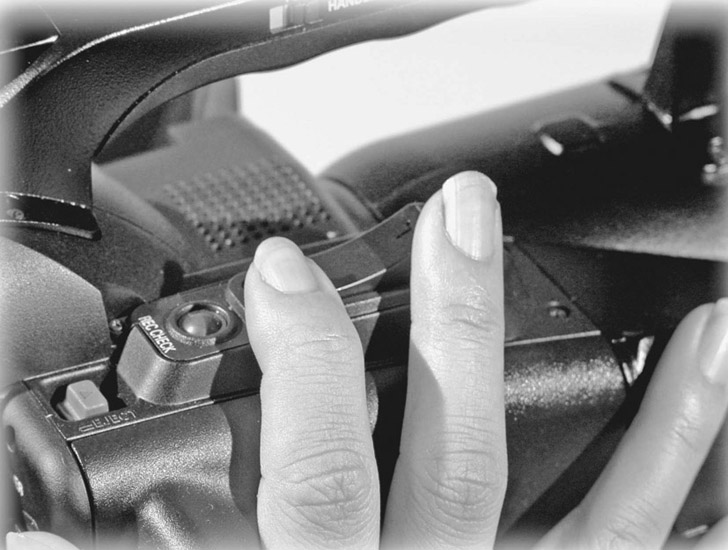
■ Figure 8.19 The servo zoom rocker-switch allows the camera operator to glide through the entire range of focal lengths available on the lens. High-end cameras provide speed adjustments for this switch, allowing even greater control.
It’s important to note that there are two types of zooms: optical zooms and digital zooms. They are not even remotely similar. An optical zoom adjusts the central lens element to magnify or demagnify the image. Although the composition and perspective of the image changes, the resolution of the video image remains the same. The optical zoom on most video cameras falls between the 10x magnification range and 20x magnification range. A digital zoom, on the other hand, is essentially an in-camera digital special effect in which the circuitry in the camera magnifies the captured video signal by selecting the central pixels and blowing them up. The loss of resolution quality is rapid and significant with digital zooms, and they should be avoided.
Media Bay
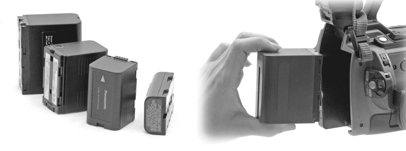
The media bay is where the video signal is recorded. Historically speaking, the signal was recorded on magnetic tape. However, as a shooting medium, the videotape cassette is now obsolete and solid-state memory cards are incorporated into every newly released camera. (Videotape remains a useful medium for project mastering and archiving.) Some common memory cards are the Secure Digital (SD) card (SDHC: up to 32 GB and SDXC: over 32 GB) and the Compact Flash (CF) card. While these are nonproprietary, others (like Panasonic’s P2 card and Sony’s SxS card) are favored by specific manufacturers (Figure 8.20). HD video requires large amounts of storage space, so memory cards are compared (and priced) by their storage capacity, which depends on the size of the card as well as the video data rate of the shooting format (p. 132). In addition, some cameras come with solid state hard drives that offer substantially more storage.
Solid-state memory cards are referred to as file-based media, because each camera take is saved as a discrete digital file. In the field, you can see thumbnail images of every scene you’ve recorded. Footage recorded on any of these formats is immediately available for editing. Memory cards can also be off-loaded to portable hard drives in the field, allowing you to reuse them again and again. Many cameras offer two card slots in their media bay, allowing you to shoot continuously without interruption.
DC Power
Video cameras run on DC power provided by batteries or via an adaptor that transforms the AC power coming from the wall outlet into DC. Despite the unlimited power supply from an AC adaptor, most shooters only use batteries, preferring the freedom of not being tethered by a cord to the wall (Figure 8.21). Batteries need to be charged to work, and it takes time to charge them. Many student shoots are aborted early because no one remembered to charge the batteries. Modern batteries are typically lithium-ion, and they are rated in amp/hours. It is a very good idea to have a clear sense of how long the camera you are using can run on a particular battery, and to have plenty of backup power. Many crews will set up a charging station on location as part of their production workflow. It is worth mentioning that batteries don’t hold their charge as long in extremes of heat and cold.
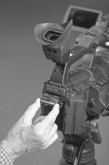
■ Figure 8.20 File-based recording on solid-state memory cards, like the SD card pictured above, offers many advantages over tape and is now the standard. The camera pictured, the Canon XF300, has two slots to allow for longer, continuous recording.
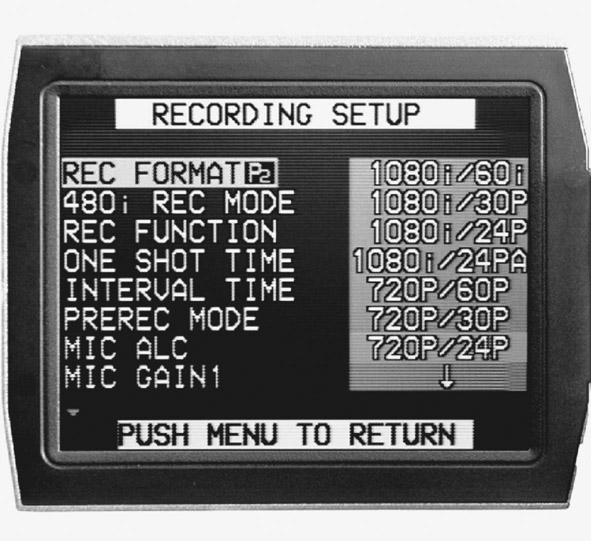
Camera Function Menus and Switches
Many cameras have their various functions and options embedded in a menu that can be accessed through buttons and viewed on the LCD viewscreen (Figure 8.22, left). On more professional cameras, some regularly used functions are located as switches, buttons, or wheels on the outside of the camera body (Figure 8.22, right), making them more easily accessible. You must consult your camera’s manual to find out how to navigate all the camera’s menus and control the functions you require for your shooting, and you should do this long before you are on location. With shooting options rapidly multiplying, camera function menus are getting longer and more labyrinthine with each generation.
■ Figure 8.21 Video cameras run on batteries available in a variety of sizes and power capacities.
One very important measure of a camera’s capability as an expressive tool is the capacity for manual control of certain critical functions, namely focus, exposure, white balance, and audio record levels. Video cameras are designed by engineers and business people, not filmmakers, and the auto functions on a video camera are designed to give the user easily obtained, generally acceptable results. Point-and-shoot simplicity is what most home video shooters are looking for, and some of these functions can also be useful in a fast and unpredictable documentary situation. But if you are making a film you will want to show to an audience in order to move people and to communicate ideas and emotions, you need to be able to control all the elements that are part of your expressive and aesthetic palette. To leave these creative decisions up to a machine is to give away your voice. Cameras that do not allow you to set your own focus, sound levels, exposure, or white balance (usually the cheapest consumer cameras) severely limit your craft and are therefore less useful. All professional and most mid-level camcorders give you the option of auto functions or manual override, and you should immediately learn how to take control of your camera’s image-making by turning off the auto functions in favor of manual control. We will look closer at how to use these functions in other chapters including Chapter 9 (The Lens), Chapters 11 and 12 (Lighting and Exposure), and Chapters 13 and 14 (Sound Recording Strategies and Techniques).
in practice
■ What Storage Media to Choose?
While your choice of camera will typically dictate which memory cards you use, within each memory card format are a variety of storage capacities. CF cards currently come in sizes from 2 GB to 256 GB, for example. Less obviously, memory cards come with a variety of read/write speed ratings, which dictate how quickly they can write the video files being stored on them. Manufacturers have periodically upgraded the specifications for their cards to keep up with the needs of video makers, so you aren’t likely to have big problems. It is wise, though, to check the speed rating of any cards you purchase and compare it to the data rate settings of the camera. In other words, if your camera is set for a data rate of 50 Mbps (megabits/sec.), then make sure your card can write at least at that speed. Data rates are indicated by a “class” system on the card. The other big factor to think of is, of course, price. The best way to think of this is in “price per gigabyte.” If you purchase a 16 GB card for $20, you are paying $1.25/GB. If you buy a 128 GB card for $300, you have voluminous storage, but you are paying closer to $2.35/GB, in which case the price may outweigh the convenience of the larger card. As bitrate options on cameras get higher, creating larger files, many people find themselves moving toward capturing video on external solid state drives (SSDs). While not every camera can accommodate this, the external drive can store much more information than a memory card can. External drives can also record at compression rates that are higher than what cards can handle (like Apple’s Pro-Res 422 format, for example).
Once you have picked the combination of image quality and storage method best suited to your project, it is wise to develop some kind of seat-of-the-pants idea of how many minutes of shooting equals how many GB of stored information. If you are filming at one GB per minute, you will go through memory cards fairly quickly, and you may want to invest in larger cards or an external drive despite the price.
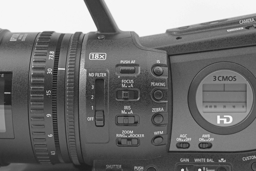
■ Figure 8.22 Some video camera functions are embedded inside menus accessible on the LCD screen (left), while other more commonly used features (like the manual overrides for focus and iris) are sometimes found on the camera’s body (right).
Audio and Video Connectors, Inputs and Outputs
Connectors are the way we get video, audio, and TC signals into and out of equipment. Output connectors are used for monitoring sound or picture, and transferring files. The main set of input connectors to consider when choosing a camera is the external microphone inputs.
External Microphone Inputs
External microphone inputs are especially important for documentary film production. The microphone input connection is another line demarcating professional and mid-level equipment from consumer cameras. The onboard microphones that come with many camcorders are insufficient for most filmmaking applications, where you need to acquire optimum-quality audio through careful microphone placement. All professional microphones use the locking three-pronged XLR connector. The advantages of this connector are a secure connection and balanced audio, which is much less susceptible to audio noise and interference. Many consumer cameras, including DSLRs, come with an 1/8ʺ miniplug connector for an external microphone input. The primary shortcoming of this connector is its flimsiness. The miniplug can easily break or pop loose under the rigors of field production. The other shortcoming of the 1/8ʺ minijack is that it is an unbalanced audio connection and is highly susceptible to interference (Figure 8.23).
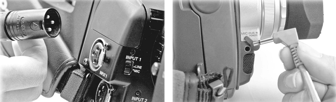
■ Figure 8.23 While higher-end camcorders come with XLR inputs for professional microphones (left), consumer cameras often only have 1/8ʺ connectors (right), which are prone to interference and are much less reliable.
Other Connectors
■ Common Audio and Video Connectors
- 1/8ʺ miniplug (line audio and microphone audio)
- XLR (line audio and microphone audio)
- BNC (video and TC)
- RCA (line audio and video)
- HDMI type A (audio, video, and auxiliary data)
- HDMI type D (audio, video, and auxiliary data)
- Mini B USB (video and audio files to computer)
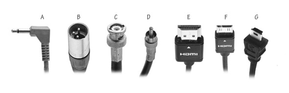
■ Figure 8.24 Common connectors for video and audio production, and the types of signal they carry.
There are four common in and out (I/O) connectors on camcorders for outputting digital video and audio (Figure 8.24). On professional and mid-level camcorders, you’ll find the High-Definition Multimedia Interface (HDMI) connector, and the USB (2.0 and 3.0). Older cameras may also feature a FireWire connector (also called IEEE 1394). These cables send digital data from the camera to a field monitor for viewing, or to your editing system. Professional cameras also come equipped with SDI/HD-SDI output (Serial Digital Interface), which uses the locking BNC connector (Figure 8.24). This interface can output uncompressed video (SD or HD) to a high-capacity hard drive (HHD) or an SSD for recording footage as you shoot. On consumer- and mid-level cam eras, you may find an RCA plug providing a composite video output for an NTSC monitor. Every camcorder has its own audio and video I/O configuration; always check your camcorder’s specific hardware. Also worth mentioning are TC I/O connectors, which allow you to synchronize cameras for multicamera shoots.
The Basic Video Camcorder: Interior
Video camcorders essentially turn light into data. The best way to understand the interior workings of a basic camcorder is to follow the progress of an image, which begins as light entering the lens and emerges as a stream of data recorded onto a memory card, hard drive, or tape (Figure 8.25).
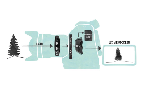
■ Figure 8.25 This diagram shows the path of light through a Canon C100 camera as it travels through the lens, is registered by the sensor, is processed by the Digital Signal Processor (DSP), and finally sent to the recording media and the image display.
The Image Sensor
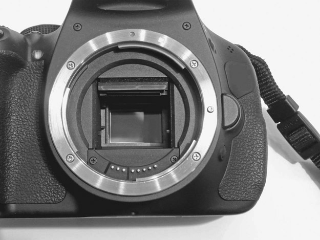
■ Figure 8.26 A CMOS chip.
The recording of the image begins with the lens gathering light from the scene and focusing it on the image plane. In video, this image plane is the surface of the sensor – either a charged coupled device (CCD) or CMOS sensor. CCD chips, once standard in camcorders, are quickly being replaced by CMOS sensors in all new cameras (Figure 8.26). Each sensor is composed of hundreds of thousands to millions of light-sensitive photodiodes, called pixels (short for “picture elements”). When these pixels are struck by the incoming light, they register an electronic charge that corresponds to the light intensity hitting that particular spot on the sensor. At this point, the way CMOS and CCD chips handle the light signal differs. The CCD employs a global shutter, meaning all the pixels are exposed to light at the same moment and register a complete image. This image is then outputted line by line, amplified, and sent to the analog-to-digital converter (ADC), where this analog signal is converted into digital data. The CCD then registers another complete frame and repeats the process. A CMOS imager, on the other hand, contains transistors with all the circuitry necessary for converting light values into voltage and then into digital data, all right behind each pixel on the sensor (Figure 8.27). Each pixel processes its own electronic charge and directly outputs a digital signal. However, rather than expose and then “read out” a complete frame, CMOS sensors have a rolling shutter, which exposes and reads out one line of pixels at a time. In other words, a CCD registers a complete frame and then outputs that frame line by line, whereas a CMOS sensor exposes and outputs one line at a time, eventually creating the complete frame. The rolling shutter is responsible for several characteristic artifacts, most infamously the jello artifact (also called “skew”), which occurs when there is horizontal movement in the frame, especially as a result of quick panning. With horizontal movement, it is possible for the top part of an object to be registered in one area of the frame, the middle scanned slightly later, and the bottom part registered even further along. The result is that vertical lines can appear slanted during the pan, and complex movement produces a wobbly, jello-like undulation in objects that should be stationary. With technological improvements, most of these artifacts are rarely seen with higher end cameras, but may still be seen with DSLRs.
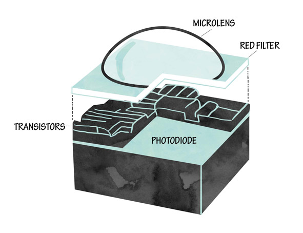
■ Figure 8.27 One CMOS pixel. The light enters through the microlens, passes through a filter (in this case a red filter), and is converted to an electrical signal by transistors on the photodiode.
Three-Chip vs One-Chip Cameras
Cameras can have either three sensors, or one. In a three-chip camera, the light gathered from the lens first passes through a prism block. This splits the image into the three primary colors of light: red, green, and blue (RGB). These three images, identical except for their color, are reflected onto the faceplates of three chips, which register the relative light intensities and translate the information into a digital signal for each color. Traditionally, three-chip cameras produced a better image than a one-chip alternative, but recently very high-quality single-chip cameras have been developed. Examples of high-end one-chip camcorders include the Black Magic camera and the Canon C100 (Figure 8.13). One reason for their high quality despite the single chip is that the sensor is very large, with a correspondingly large number of pixels. These sensors include a Bayer Pattern Filter, which divides the pixels into three groups sensitive to three different colors of light creating Red, Green, and Blue signals on the one sensor (Figure 8.28).
■ Figure 8.28 A Bayer Pattern Filter separates light into three different colors in a mosaic pattern. The red pixels are on the right, the green (which predominate) are in the center, and the blue are on the left. (See plate section for color.)
White Balance
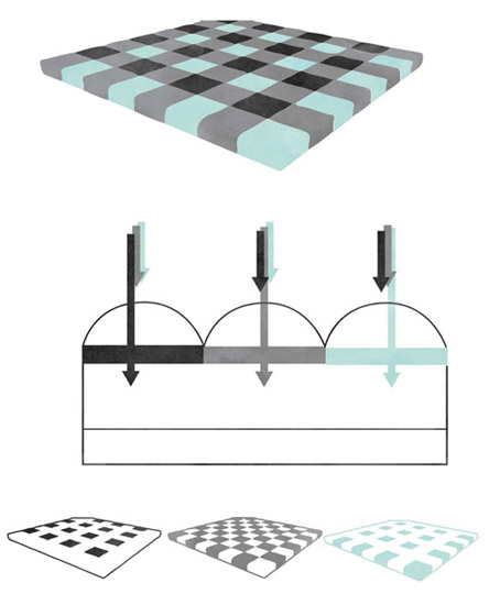
As we will see in Chapter 11, light from various sources has different color values. The sun is very blue, while a Tungsten light bulb is more orange (Figure 11.9). While the human eye compensates for these variations, your camera’s ability to do this is limited. For your camera to reproduce colors accurately, you must take care to white balance each time you change location or lighting conditions. White balancing means adjusting the imager’s color circuitry to compensate for the color temperature of different light sources. On nearly every video camera, there are two easily accessible color temperature pre sets, one for daylight (5,600K) and one for tungsten light (3,200K). In addition, many cameras provide a way to manually set white balance, which is more accurate than a factory preset. Setting white balance is accomplished by filling your frame with something white and matte (like a white card or sheet of paper) that is lit with representative light, and then pressing the manual white balance button (Figure 8.29). Whether the white card is reflecting the bluish tint of daylight, the amber tint of tungsten bulbs or the greenish hue of fluorescent lights, the camera adjusts the R, G, and B sensitivity levels until that card is rendered as “white.” On many cameras, you can also assign these manually determined white balance settings to user preset buttons (Figure 8.29). Remember that white balancing must be done every time your light source changes! It may seem like a chore to reset white balance constantly, but it will soon become second nature, especially after a couple of shoots where all of your exteriors are blue or your interiors bright orange. Many documentary interiors offer a mix of different light color temperatures. You need to figure out what is important in the image, typically skin tones, and set your white balance for the light values hitting that subject.
■ Figure 8.29 White balancing. All video cameras have a way to balance the image sensors to a variety of color temperatures. On this Canon XF300, to do manual white balancing you must first switch off the auto white balance function (A). A user can then manually set color temperature balance for each scene (B) or recall daylight and tungsten presets (C). Also note the Gain Switch.
It is worth noting that many DSLRs do not have a quick and easy way to white balance. You will likely have to enter the camera function menu system to access a manual white balance control. The same is true of smaller camcorders as well.
Gain
Gain is a measure of the electronic amplification of the video signal coming from the image sensor. Gain is important, as increasing it will increase the light sensitivity of the camera. This would seem to be an advantage. The problem is that increasing gain also increases the electronic noise that is visible in the image. Gain is considered an exposure adjustment (Chapters 9 and 11) of last resort, to be employed when you absolutely need to get the shot but there simply isn’t enough light for a decent exposure. When you increase the gain, the image suddenly appears much brighter. Gain, however, seriously compromises image resolution and contrast and increases video noise, unwanted electronic aberrations and artifacts. Most cameras offer three preset gain settings: 0 dB for low gain, 9 dB for medium gain, and 18 db for high gain (Figure 8.29). These can sometimes be reset manually to offer less drastic boosts in light sensitivity. Most cameras also have an automatic gain control (AGC), which, like most auto functions, should immediately be turned off in favor of the manual settings. On DSLRs, the gain is reflected in the ISO or “film speed” settings. Here again, the camera will cheerfully boost the ISO to 1600 or even 3200 or more, but the result will be a very noisy image. As a rule, stick with an ISO of 800 or lower to avoid problems.
Shutter Speed
Shutter speed is an important variable. The standard exposure will be half that of the frame rate of the camera: for NTSC, it is 1/60th of a second for 60i and 1/48th of a second for 24p. For PAL, it is 1/50th of a second for 50i and 25p (Figure 8.5). Unless you have a good reason for changing your shutter speed, you are well advised to set this manually and leave it alone. Many cameras (especially DSLRs) will compensate for added light by changing the shutter speed to shorter amounts of time like 1/100th or even 1/1000th of a second. The problem with this is that the camera will appear to “stop” motion, giving moving objects and people a jerky look as they cross the screen. While this may be useful in certain applications, such as sports photography, in general it is undesirable, as the blur of moving objects filmed at 1/60th or 1/50th of a second appears much more natural to the human eye. Some cameras offer lower shutter speeds (achieved digitally), which can occasionally be helpful in low light situations.
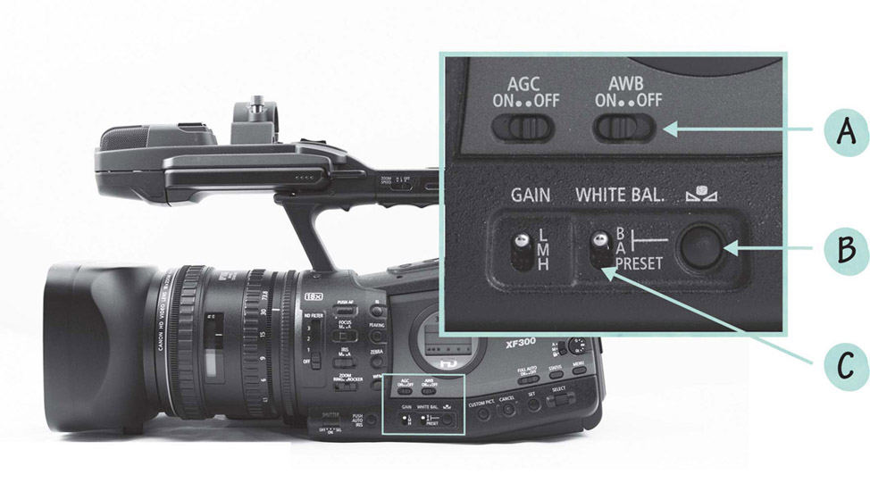
ND Filters
Another option for controlling exposure is the neutral density (ND) filter. This is simply a gray filter that cuts the amount of light entering the lens. The advantage of using an ND filter is that it allows you to alter exposure without changing your f-stop, something you might want to do to maintain a narrow depth of field, for example (Chapter 9). ND filters are a common option in video cameras. They are mounted internally and adjusted through an external switch (Figure 8.30). If you are using a DSLR, you will need to mount an external filter. For more on ND filters, see Chapter 11.
■ Figure 8.30 Neutral Density switches activate filters that cut down on the amount of light entering the lens.
The Analog-to-Digital Converter
In cameras that use CCDs, each chip converts the light values that strike it into voltage, and sends this analog electronic signal to an ADC. There, the signal is transformed into digital data, meaning binary code (a series of 1s and 0s). Cameras with CMOS sensors don’t have to do this, as the imager itself has circuitry that converts analog picture information to a digital signal. In all cameras, the audio input signals are converted from an analog electronic signal into digital data using an ADC.
The process of transforming analog information into digital data is called quantizing. It requires the camera to sample the constantly flowing stream of voltage information from each pixel and then ascribe to it discrete digital values. Sample rates are about 50 million samples per second and don’t really vary for picture (although they can for sound). The amount of color information in each sample is expressed in terms of bit depth. The more bits, the larger the sample size (in bits/sample), and the better the color and image detail will be. Currently the standard for video is 8-bit per channel, which gives you 256 choices for each color. These choices combine (256 red values x 256 green values x 256 blue values) to offer a total of 16.7 million colors, also known as “millions of colors” (Figure 8.31).
The Digital Signal Processor
The digital video from the sensor(s) and the audio data from the audio ADC are sent to the digital signal processor (DSP) to create the final, digital signal. The DSP is the most complex part of the entire digital video system and works with algorithms specific to the camera’s format (such as AVCHD, XMF, and XDCAM). Basically, the DSP combines the three sets of color information from the sensor(s) or determines the brightness and color value of every pixel in every frame of video to create the full-color image, along with the audio signal. However, at this point, these uncompressed images contain an enormous amount of data. HD video generates around 150 MB/sec of data. At that rate, you would fill up a 64 GB memory card in about 6 minutes. This is simply way too much data to record easily on card media. So when processing raw video information, the DSP is forced to reduce the amount of data it sends to the recording media. To avoid losing too much resolution quality, the DSP uses two main processes to accomplish this reduction: compression and color subsampling.

■ Figure 8.31 Bit Depth is an important aspect of the digital image. Shown here (clockwise starting with the upper left image) are 2-bit (black and white), 4-bit (16 shades of gray), 8-bit color (256 colors), and 24-bit color (16.7 million colors). (See plate section for color.)
Signal Compression and Codecs
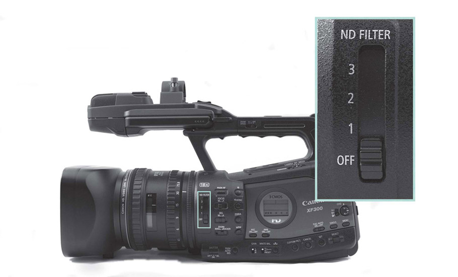
The critical juggling act of all video formats is how to reduce the amount of image data while maintaining as much quality as possible. If you compress too much, the image quality suffers; if you don’t compress enough, the files are too big and too slow to work with. Compression is the method used to reduce the amount of data by discarding visual detail that is either imperceptible to the human eye or redundant. The data compression algorithms are essentially software programs that perform a series of operations on the digital image. The programs that perform this compression are called codecs (for “compression/ decompression”). There are multiple standard codecs in the world of digital video (MPEG-2, MPEG-4, and H.264, for example), with new ones being introduced regularly. However, when we are talking about video camera encoding, each manufacturer puts a proprietary codec as an envelope or file wrapper around the compressed file. For example, Panasonic’s format utilizes the AVC-Intra codec, which is based on the H.264/MPEG-4 AVC standard (the codec used in Blu-ray). Sony uses the XDCam codec as a wrapper for MPEG-2 files. As you can imagine, there is constant negotiation with the most popular editing systems (AVID, Final Cut Pro, and Adobe Premiere Pro) to support these compression schemes, which, thankfully, they usually do (Figure 8.32). Recording formats and their proprietary codecs are numerous and constantly changing, so rather than look at them specifically, we will look at the essential principles of compression, especially as they pertain to image quality. Understanding some basics about compression is important because it has a bearing on choosing a shooting format, your anticipated workflow, and what viewers see on the screen.
Compression schemes use several approaches to shrinking file size. The amount of data kept can be surprisingly small. For HD video, the uncompressed file can be as much as 20 times bigger than the compressed file. In other words, the picture information is reduced to just 5 percent of its original amount, yet the image still looks surprisingly good. How does the codec achieve this? One strategy for compression is to remove redundant information. Redundant information is the data from visual details that are repeated, from pixel to pixel and frame to frame. For example, say you have a shot of a red ball rolling across a green lawn. The pixels along the path of the ball change from green to red as the ball travels, but the rest of the frame remains exactly the same green, frame after frame. It would take a great deal of space to re-record all of the common and repeated luminance (light) and chrominance (color) values for every pixel in every frame. For 1080i HD, we would need to re-record the same repeated “green” values 2,073,600 times for every frame (minus the red pixels that make up the ball). The codec reduces all of this common information to a smaller file size by recording the numeric value for “green” once and then indicating that every other pixel in each subsequent frame (except for the red ball pixels) is “just like that first one.” The rest of the information is then tossed out. Later, when we play back that image, the codec decompresses that information by reconstructing the data through duplication of that one saved numeric value for the “green” areas of the frame. Video codecs can work so well that the compressed image is hard to tell from the uncompressed source image.
■ Figure 8.32 This setup menu in Premiere Pro reveals just how many format and codec variations exist these days.
Another key distinction among compression types is VBR vs CBR. Many compression types, including MPEG-2, are variable bit rate (VBR). VBR codecs compress less when there is more movement or color shifting from frame to frame than when the image is more static. Others, like Apple ProRes 422, are constant bit rate (CBR), meaning that they compress the image the same amount regardless of the content. VBR works very well for shooting and display, but it creates problems for editing systems because they prefer CBR data. Some edit systems can handle variable bit rate data better than others, but don’t be surprised if you end up needing to transcode your VBR footage to a format more suitable for editing.
Color Encoding and Subsampling
The other main method codecs use to reduce file size is the elimination of color information. The video image has two components: the element of the video image that determines brightness (shades of black and white) is called the luminance signal, and the color component of the video signal is called the chrominance (or chroma). Chrominance is made up of hue, which determines the tint of a particular color, and saturation, which determines the intensity of the colors. An accurate color blend is created by mixing the chrominance and luminance information for the three primary colors (R, G, B) with the brightness information.
Color sampling refers to the number of times brightness (luminance) and color (chroma) information are measured and translated into data by the DSP. Color sampling is expressed as a ratio of luminance samples to blue samples to red samples (note that this is different from signal sampling and its relative, bit depth, which occur earlier in the analog to digital conversion). The information for green is not sampled because it can be interpolated given the data for luminance, blue, and red. Color sampling involves throwing away relatively large amounts of color information. Because the human eye is capable of perceiving very subtle variations in brightness but relatively fewer shifts in color tonalities, all video formats keep 100 percent of the luminance information, but much less blue and red information. A full sample is represented with the integer 4, so a color sampling ratio of 4:4:4 would mean that all luminance data, blue, and red colors are sampled equally and fully. A ratio of 4:1:1 would mean for each four luminance pixels, only one each of the blue and red pixels are saved.
Chroma subsampling is one way compression algorithms eliminate color data that may not even be perceptible in order to save space. Many HD cameras offer multiple color subsampling rates, including 4:2:2 and 4:1:1. Some cameras have 4:4:4 uncompressed (or raw media) available for external display or recording via a cable or external attachment. For an illustration of color subsampling, see our companion website (www.routledge.com/cw/Anderson).
■ Data Rate
Throughout your workflow, you’ll need to be aware of the data rate for your particular format. The data rate is expressed as a bit rate in Megabits per second (Mbps). This determines, among other things, the amount of storage space you’ll need for your project. Format data rates are determined by a number of factors, including whether you’re shooting SD, HD, or 4K; the frame rate (60i, 24p); and the specific quantizing and compression factors of the record format (DVCPRO-HD, XDCAM-HD, AVCHD). Some cameras will let you choose the bit rate (35 Mbps or 50 Mbps, for example). Some broadcasters use bit rate to define minimum acceptable quality for broadcast. The BBC minimum standard for commissioned work, for example, is 50 Mbps. A media data rate calculator will give you a good idea of how big the files you accumulate will be at different data rates, so that you can make the best choice for your budget and workflow. There are many calculators you can download (as software or as smartphone apps) that include virtually every shooting format and codec available (Figure 8.33). Many cameras now list data rate options.
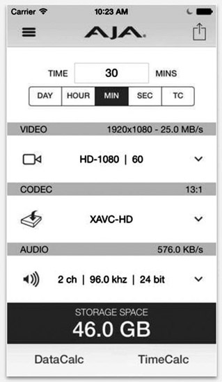
■ Figure 8.33 Media data rate calculators, like this free one for iPhone from AJA Systems, are a handy tool for calculating data storage needs.
■ Monitoring and Display
In addition to a viewfinder and an LCD viewscreen, most video cameras offer the possibility of sending a signal through connectors to an external monitor. These connectors are of several types, based on different analog and digital signal formats. In the field, you will typically use an external monitor either because the viewing options on your camera are poor, as can be the case with many DSLRs (Figure 8.34, left), or because there is some need for more critical viewing. A director and cinematographer might need to share input on the look of an image, for example, or there might be a particularly complex setup involving multiple light sources with different color temperatures. Field monitors are typically flat screen LCD displays, and come in a variety of sizes. Quality can vary widely, as can price. Typically those of smaller size, like 6 inches or less, will mount on the camera or the shoulder mount of a DSLR, while larger monitors can stand alone. Often they will come with a hood to isolate the screen from ambient light (Figure 8.34, right).
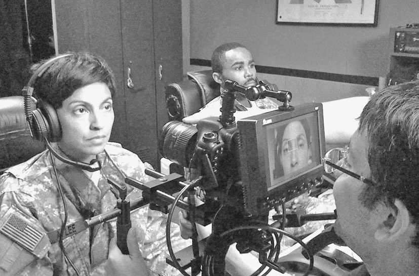
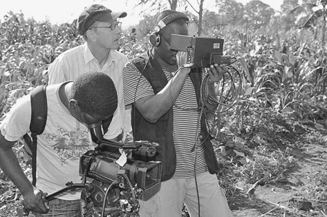
■ Figure 8.34 Shooting with a Canon 7D and a Marshall monitor mounted on the camera (left). A larger field monitor with a hood is useful for outdoor shooting (right).
If you use an external monitor, you will need to calibrate it. To do this, you should set your camera to generate color bars, usually a menu option. These bars allow you to set the color signal to match that of your camera’s viewing system (particularly important for NTSC). Monitors vary widely in their ability to accurately render color and picture information, so use the information you get from them judiciously.
■ Calibrating a Monitor
Calibrating a modern digital monitor means setting the white balance, the brightness, the contrast, and the chroma saturation. What follows is partially adapted from an excellent article by digital imaging technician Bennett Cain.9
The first question to ask yourself is “What standard am I setting the monitor to?” The standard for HD video, and the default for most digital cameras, is called ITU Rec 709. It comes from the International Telecommunications Union (p. 111), and Recommendation 709, which includes color space, among other things, and came out in 1990.
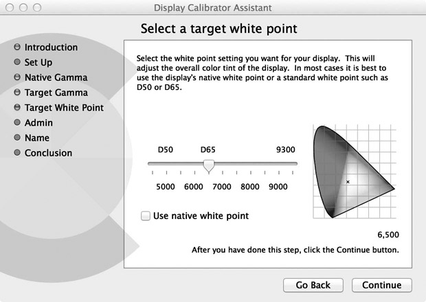
■ Figure 8.35 In this window, you can see a representation of the Rec. 709 color space, with the small x marking the spot where a neutral white can be found. (See plate section for color.)
In the Rec 709 standard, the white should be set at a color temperature of 6500K or D65 (Chapter 11). On a Mac computer, there is a calibrating tool that can be used to make the color match this setting (Figure 8.35). If you have a choice for gamma, as you do on the Mac, you should set it at 2.2.
To set up an external monitor, you will use color bars. In the field, your camera can typically generate these. In the edit room, your nonlinear editing (NLE) system can generate color bars.

■ Figure 8.36 This image shows a color bar display properly set for white, black, and chroma levels. (See plate section for color.)
Color bars vary depending on the hardware and software you’re using. Standard HD bars will include the full color spectrum, plus black and white sections. First, take a look at what correctly set bars look like (Figure 8.36). The white setting, your luminance level, is subjective in the sense that you are setting it by eye. Typically, you will want to adjust the contrast until the white (second from the left on the bottom group, Figure 8.36) reaches a maximum, then back it off a little. Then you will want to set the black level using the three small black bars on the lower right (Figure 8.37). Basically, you want to set monitor brightness and contrast so that the difference between the center and the right bar just disappears. The settings for each variable might be adjusted through a knob or a menu item.
Higher end monitors will have a “blue gun” that provides a way of seeing only the blue signal. If you can do this, your calibration of color values will be easy (Figure 8.38).
If you don’t have a blue gun option, you will have to adjust the chroma by eye. Everyone uses different clues, but a common one is the gray of the first bar on the top left, which should contrast notably from the white on the lower set of bars (Figure 8.36).
Again, every monitor is different, and there are many options for setting them. A high-quality monitor, whether for field or studio use, is quite expensive. The best advice is to do what you can in the field, record bars, and work with those to tweak your material when you get to the edit room. This will be especially useful if you’ve shot with more than one camera.


■ Figure 8.37 In this typical color bar display, the brightness of the three small bars on the lower right (called the pluge, from “picture line-up generation equipment”) can be used to set brightness level. In the close-up section of the bar display (right), the setting has been adjusted so that the difference between the two bars on the left of the pluge almost disappears. See color insert.


■ Figure 8.38 Setting up a monitor with a blue gun. Adjust the chroma level on the display until you’re looking at solid, alternating bars of equal value. The image on the left shows an incorrectly adjusted chroma because the third and fifth bars show small stubs at the bottom. On the right, the chroma has been set properly. See color insert.
The release of Werner Herzog’s 3D documentary Cave of Forgotten Dreams (2010), about the prehistoric Chauvet cave paintings, and of Wim Wenders’ Pina (2011), an Oscar®-nominated 3D profile of the famous choreographer Pina Bausch, opened a new chapter in the history of documentary. Although these projects were produced with large budgets by documentary standards, the availability of consumer-level 3D camcorders suggests that there is a real future for documentary in 3D (Figure 8.39). 3D cinematography was first introduced in the 1950s as one of several efforts to recapture viewers lost to television, and it has been regularly reintroduced (and improved) with each subsequent decade. There is a lot of debate as to what we are witnessing now, after the first decade of the twenty-first century. Some say that 3D digital video represents a “revolution” that will change filmmaking as we know it and make two-dimensional cinematography obsolete. Others claim this is a nostalgic craze, just another movie-making gimmick. Our opinion is that 3D is here to stay, and likely to improve rapidly. In fact, we are starting to see devices that make it possible to have a 3D experience in a home context. 3D probably won’t displace 2D movies, but it will settle into its own market niche and share screens with traditionally made films.

■ Figure 8.39 Pina, the story of the life and work of modern dance choreographer Pina Bausch, was the first 3D film to be nominated for Best Documentary Feature at the Academy Awards®.
As with all new technologies, the availability of 3D is not a reason to use it. 3D was an appropriate technology for Pina because it served the story, putting viewers in the midst of the dancers to give a vivid sense of the physicality of the dance movements created by this leading choreographer.
■ Broadcast Standards Worldwide
Once your documentary is finished, you will confront the sometimes daunting fact that broadcast standards vary from country to country. You will soon find that there are two main groups of television standards based on the historical standards of NTSC and Phase Alternate Line (PAL). These standards ensure compatibility between image recording and display processes across all nations that adopt the standard.
In the United States, Canada, Mexico, South Korea, and some other countries in Latin America and Asia, the broadcast standard is defined by the ATSC, and is developed from the older NTSC system. Other digital television standards around the world are Digital Video Broadcasting-Terrestrial (DVB-T), which is used throughout Western and Eastern Europe, Russia, Australia, and many nations throughout Asia and Africa; Integrated Services Digital Broadcasting-Terrestrial (ISDB-T), used in Japan, Brazil, and most of South America; and Digital Terrestrial Multimedia Broadcast (DTMB), used by China and Hong Kong. As of the writing of this edition, global digital television standards were still in the process of being adopted by many nations. The target date for the complete global transition from analog to some form of digital broadcast is 2020. Just as the ATSC standards are based on the need for backward compatibility with the old NTSC standards, DVB-T is based on the widespread former European analog standards PAL and SECAM (Séquential Couleur Avec Mémoire). Many professional cameras have the capacity to switch formats based on these standards.
■ Conclusion
If you’ve read this chapter up to this point, you probably understand that the truest thing one can say about digital video is that it’s constantly evolving, improving, and changing. Do not expect things to ever settle down to some sort of manageable stasis. Given the variety of options and the speed of technological change, you should try to think through your workflow carefully, and plan as far ahead as you can, thinking about postproduction as well as shooting. In addition, you need to consider that all of these new technologies come with advantages and trade-offs. One example might be 4K. The image is great, but if it comes in a camera that you can’t actually handle easily, it might not be the best choice for an observational documentary. In addition, the workflow for 4K can add a big burden in terms of both budget and labor. Just remember that the quality of the image is important, but the story and your relationship with your subjects should be the main driving force behind any decisions you make about equipment.