2. Creating and Using DSLs
Introduction
The purpose of this chapter is to touch on all of the principal aspects of defining a domain-specific language (DSL) with the Microsoft DSL Tools. We also introduce an example scenario in which the DSL Tools are used. The later chapters will then go into more detail on each topic.
This chapter has three sections. First, we introduce a development group that finds that the DSL Tools improve its productivity, and we look at why that is so and something of the process that the group follows to create and use the DSLs.
Second, we look at the practical steps of creating a DSL, touching briefly on each of the topics that will be discussed in turn in later chapters.
Finally, we take a look at the main components of the DSL Tools architecture.
By the way, we practice what we preach. The DSL Tools are generated, bootstrap fashion, from a DSL definition. Like any substantial DSL Tools-based example, the core of the system is the generated code, and that is augmented with a quantity of hand-written code.
Process: Incremental Development of DSLs
You define a DSL because you want to create models by which software is generated or controlled. It is of course possible to create notations with DSL Tools that are just used informally, and some DSLs may start life that way. But for the majority of cases, the DSL is essentially a means to parameterize a generic framework; you have an application or a component that you use many times, although with some variation from one usage to the next. A DSL is one way (among many possible ways) of allowing the developer who uses the framework in a specific application to provide specific values for its variable features. Development of the DSL and its framework thus go hand in hand. Toolkits like the DSL Tools have removed one obstacle by making it easy to define the DSL and develop tools to support it. However, developing the framework is still a time-consuming and potentially risky task.
To mitigate the risk, you don’t develop the framework and its DSLs all at once from scratch. Instead, you begin with existing code that works for a specific application, and you gradually parameterize it, progressively identifying those parts that should vary from one application to another and making them dependent on DSLs.
Generalizing an Application: Identify Variability, Discover DSLs
The (fictional) consultancy firm of CJKW manages software projects for client companies and provides tools to help that process. One of the key ingredients for success, CJKW has found, is to monitor issues—reports of bugs or other problems that arise during the project—and their eventual resolution. Issue logs are kept in a database; reports can be generated showing what issues are outstanding, how fast they are being resolved, and so on. However, the details of this requirement vary from one customer company to another. Some think of an issue as just being either outstanding or fixed, while others see it as progressing through a detailed set of steps such as approved, assigned, blocked, solution proposed, and so on.
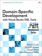
CJKW began by adopting the Issue Tracker Starter Kit, a small application that provides a web client and can run on SQL Server, which the company obtained in source form from the ASP.NET website.1 (The original version, based on .NET version 1.2, can be found by searching in the ASP.NET website.) Out of the box, the Issue Tracker allows users to create a record of each issue (Figure 2-1) and to query the database to list all the issues that are in a given state. An administrator can define a set of allowed states, and users can set the state of any issue to one of those values. This allows different states to be employed from one client to another. But one of CJKW’s earliest customers has a more stringent requirement, that there should be some constraints on how states can be changed—for example, that you can’t go straight from Unassigned to Fixed.
Figure 2-1. The web interface to the Issue Tracker application
Looking at the existing code, CJKW’s in-house developers identify the point at which the menu of allowed states is presented to the user. They insert some code that computes the set of permitted next states from the previous one. (After an initial test, they realize that they must always include the current state in the allowed list so that the user has the option of leaving the state unchanged.) The relevant fragment looks like this:
string[] nextOptions = new string[]{};
if (!string.IsNullOrEmpty(currentState))
{
if ("Unassigned"==currentState)2
nextOptions = new string[] {
"Unassigned" // allow leaving state unchanged
"Approved",
"Rejected",
};
else if ("Rejected"==currentState)
nextOptions = new string[] {
"Rejected", // allow leaving state unchanged
};
else if ("Approved"==currentState)
nextOptions = new string[] {
"Approved", // allow leaving state unchanged
"Fixed",
};
else if ("Fixed"==currentState)
nextOptions = new string[] {
"Fixed", // allow leaving state unchanged
};
}
else
{ // New Issue
nextOptions = new string[] {"Unassigned"};
}
The first instance of this application works well at the customer site, and CJKW decided to use it with its other clients—though of course with more or less differing requirements in each one. The development team’s initial response is to copy the existing code and modify it to meet the new requirements at each customer site. But as CJKW thrives and more customer engagements arise, it becomes clear that this is an unscalable strategy that creates too many variants of the same code. To be fair to CJKW, it wasn’t clear at the outset that there would need to be so many variations on the same application, and it wasn’t clear which bits would be the same all the time and which bits would vary. So for a while the developers create a new variant for each customer, adapt the code for each new requirement, and often take the opportunity to make some architectural improvements at the same time. But eventually, Devika, the lead developer, sits back and surveys with some concern the source repository, full of half-forgotten variations of the same system.
She does a series of text comparisons on the source of the applications that have been developed to date—a variability analysis. It turns out that the above fragment of state transition code is one of the main things that changes from one installation to another. The team therefore decides that this part of the code should be generated from a model. There are other miscellaneous bits of code that change from customer to customer, but this particular aspect is consistently variable, so automating its development would save a lot of time—both in creating the code initially for each new application and in making any changes later.
In this way, the need for generation in a particular area is identified bottom-up, by considering necessary variations in the implementation. Some other variations were found in the diff, but they turn out to be incidental, without significant effect on function.
To realize its plan, the team must produce two things:
• A DSL definition
• A body of code, derived from their current code base, the variable parts of which can be generated from the DSL
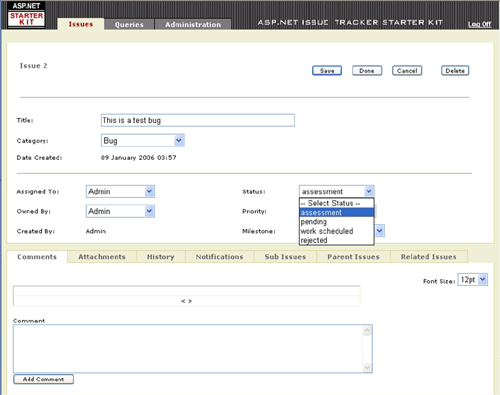
What kind of DSL is suitable for this purpose? Well, in this case, “states” seem to suggest state diagrams, so let’s hope the team didn’t spend too long pondering that one. Figure 2-2 shows an example of the DSL they produce.
Figure 2-2. An Issue State definition
But just for a moment let’s consider other possible variations. Some customers may, for example, wish to get a regular report containing a graph summarizing how promptly issues are being dealt with. But perhaps there are two alternative algorithms for cooking them up—some customers favor one method, and others prefer the other method. One way of dealing with this is a compiler switch: #if ReportType1 ... #else ... #endif. (There is also of course the option of a runtime flag, which we’ll discuss later in this chapter.) Now suppose there are many such choices, some of them multivalued and some of them interdependent, and some of them requiring more subtle variations in the code than just including a block or not. Some bright team member comes up with the idea of encoding all the choices in XML and then generating the required code from that. This is where the DSL Tools come in, since they can read the XML file and use text templates to generate the code from choices encoded in the XML. In this case, the DSL is just the XML, and the strength of the DSL Tools is in generating the code from this model. In situations where the DSL is more sophisticated, embodying relations between entities—such as workflows or complex static relationships—then it is useful to think in terms of a diagrammatic DSL, and the diagram editing capabilities of the DSL Tools become useful. For most of the examples in this book, we’ll discuss diagrammatic DSLs, if only to show off the full feature set.
This DSL looks similar to the UML state diagram notation—a deliberate choice that was made so that newcomers can readily understand its intention. But it is without many of the UML features that are not required here, such as nested states, guards, and other decorations on transitions. The semantics of this language will be expressed entirely by the code generators written for this application.
Top-Down and Bottom-Up
Hearing of the decision to generate code from state diagrams, Annie, the chief analyst, isn’t surprised. She recounts that whenever she visits a new client to discuss its project management requirements, the discussion pretty soon gets around to issue tracking. Having now had plenty of experience with these clients, Annie immediately asks them about the states they need in their issue logs. The customers aren’t always clear about this at first, but Annie finds it helps to draw a diagram of the states and their possible transitions on the whiteboard and to discuss the situations in which users would change the states and why. Annie remarks that she could have told team members they’d use state diagrams, without their having to go through their variability analysis on the code. And all those binary flags about the reports? Well, for months she’s had a form she fills out with new customers, with checkboxes for just those choices. Devika folds her arms and wonders aloud whether Annie can tell her about next month’s test results, too.
This illustrates that there are two approaches to developing a DSL, one is observing necessary variations in the code, and the other is looking at the variations at the conceptual level—the states and transitions rather than their code. The virtue of the first approach is that it ensures every feature of the DSL is justified by a generative need; the value of the second is in expressing the variations in terms of the customers’ needs and in terms they can discuss. It can be argued, therefore, that the top-down approach tends to lead more quickly to a substantial and self-consistent model, and a longer-sighted one. On the other hand, it can be too easy at the conceptual level to concoct a complex model that is impractical to implement. So, in practice, it is effective to alternate between top-down and bottom-up techniques, working incrementally to avoid the risk of a big upfront investment but regularly standing back to check for consistency.
One of the effects of using a DSL is to bring the implementation work much closer to the user’s conceptual space rather than that of the implementation. The DSL is (or should be) expressed in terms of ideas that make sense at the level at which it deals: issue states and transitions rather than database rows and cross-referenced keys. And in a DSL, we’re talking here about issue states and transitions—not just any old states. Suppose that in each issue log we want to record the reason for the most recent transition and provide that the allowed reasons will be constrained by transition (so that for example, you can say “fixed” or “given up” for a transition to the closed state but not for the transition from “unassigned” to “assigned”). In that case, a list of allowed reasons will be an attribute of each transition.
The DSL captures the variable parts of the conceptual space. The transformations that generate code embody the generic architecture—if you like, the language of patterns—of applications in the DSL’s domain: the DSL authors’ knowledge about how to create applications or components in that domain, given a statement of requirements in the DSL. Whereas it is an insoluble problem to generate automatically the application that meets a general requirements statement, it is quite easy to generate applications in a restricted domain that meet the requirements expressed by a language specific to that domain.
Developing the DSL: From Sketches to Domain Model
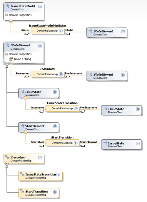
After experimenting with many sketches of state diagrams—and taking into consideration both the variability in the code they want to generate, and the concepts that customers want to express—the developers come up with a definition of the language. The core of this definition is the domain model, which states the kinds of things that are dealt with by instances of the language (individual state diagrams in this case). Using the DSL Tools domain modeling tool, they create the diagram in Figure 2-3 (we’ll see how in the next major section).
Figure 2-3. Initial DSL definition for the Issue State language

A domain model is the central part of a DSL’s definition. It defines, among other things, domain classes (the round-cornered boxes) and domain relationships (with square corners). The model defines the classes of elements there may be in instances of the language and the relationships there may be among them. Reading this diagram from the top left downwards, it states that:
• An IssueStateModel consists of any number of StateElements; the relationship between the two is called IssueStateModelHasStates.
The solid line representing the two arms or roles of this relationship show that this is an embedding relationship. In a running designer,3 all the elements are linked in a tree of embedding relationships.
• From the point of view of an IssueStateModel, its collection of State Elements is accessible through its property States. From the point of view of a StateElement, its parent IssueStateModel is accessible through its property called Model.
• Each StateElement has a domain property called Name, whose type is String.
• There are two kinds of StateElement: IssueState and StartElement. (The IssueStates are represented by boxes in the instance example in Figure 2-2, and the black dot is a StartElement.)
• Any StateElement may be related to any number of other StateElements through a relationship called Transition. Each StateElement has properties Successors and Predecessors, which provide access to the related StateElements. (Transitions represent the arrowed connectors between states on the diagram.) The dotted line representing this relationship shows it to be a reference relationship, cross-linking nodes of the embedding tree.
IssueStateModel is called the root of this DSL, and—as is usual—each instance of the root is represented by a whole diagram when the DSL is presented in a designer. It is also the root of the XML tree when instances of the language are saved to file.
Domain models are the subject of Chapter 3.
Domain Model and Presentation Are Separate
The Domain Model—the classes and relationships part of the DSL definition—defines just the concepts dealt with by the DSL. It does not define how to present the material as a diagram. (In fact, as we observed in Chapter 1, it can often be useful to create a DSL without a diagrammatic presentation.) To do this, the team defines a set of Shapes and Connectors—boxes and lines, if you like. In the Issue State DSL, the correspondence between shapes and domain classes is straightforward: each IssueState is represented by an IssueStateShape, and each Transition is represented by a TransitionConnector.
There is a variety of basic shape and connector types available, and there are several ways of displaying information within a shape, as lines of text, lists of values, or variable icons. Color, line thickness, shading, and other characteristics can be varied.
After defining a set of shapes, the DSL author must define a set of shape maps. These define which shape or connector displays each domain class or relationship as well as what determines the text or other variable features of the shapes.
In a running designer, while a DSL user is editing a DSL instance (as in, for example, Figure 2-2), it is of course the shapes and connectors that appear on the screen. However, for the most part the domain properties that are displayed in the properties window when one of those shapes is selected are those of the underlying model element, and the editing or other operations that are performed are defined on the model elements. The shapes and connectors on the diagram are kept up to date by a process known as “view fixup,” which is managed by the DSL Tools presentation framework.
The clear separation between presentation and underlying model means that an author of a DSL definition can, within reason, change the way in which the domain model is presented without having to change the model itself.
Another aspect of this separation appears when the DSL user saves an instance to file. Two files are actually generated, one containing just the domain class and relationship instances and their domain properties, and the other with layout information for the diagrammatic presentation. If the latter file is thrown away, the diagram will be recreated automatically. The layout will be a mess, but the shape contents and the connections between them will be correct. The particular value of this separation is that tools can easily be written that accept the model, uncluttered by the incidental layout information.
Presentation is the subject of Chapter 4.
Refining the DSL
How did the team come up with the DSL definition? The essential process is to look at the sketch instances and identify the different types of things you are drawing—not forgetting a domain class for the whole model.
Tip: Work from instances
We have worked from prototype instances of the notation we want in order to create the domain model—another kind of “bottom-up” working. Sample instances—usually drawn on the whiteboard—are useful for examining the proposed domain model.
Once a domain model is proposed, Annie and Devika draw more example instances of it to see whether it covers the cases they need and also to see if it covers more than they need. A collection of StartElements and nothing else would be a valid instance of the model as it stands; would more than one StartElement on a state model be allowed? Would a StartElement unrelated to any IssueState be allowed?
Together with the domain model, the DSL authors can define a set of validation constraints (covered in detail in Chapter 7) expressed in C#, which can be used to prevent the DSL user from drawing (or at least saving) such oddities.
In considering what should and should not be allowed as a valid Issue State model, the developers are thinking both about whether such a state model would mean anything useful to its users and about whether they can generate sensible code from it. Once they have defined the bounds of what users can draw, Devika can make those assumptions in the design of the code generators.
Whatever the answers to these questions, they are much easier to ask and discuss in terms of a language than in terms of variations in the source code, tables, or APIs. Working “top-down” from language to code helps ensure architectural consistency.
Driving the Framework from the DSL
Now a generator can be written for the variant pieces of code. The first candidate for generation is the fragment that sets the menu of permitted states. When we saw it earlier, it had been hand-written to support a particular state model. Devika begins by copying the C# file to a text template file (that is, with filename extension .tt instead of .cs) and running the code generator. Without any modification, the file just regenerates the original .cs file. But now Devika inserts code-generation statements at the key places where the code should depend on the content of the state model.
// ... preceding section remains as it was in original source
string [] nextOptions = new string [] {};
if (!string.IsNullOrEmpty(currentState))
{
<#
StateElement startState = null;
foreach (StateElement fromState in this.IssueStateModel.States)
{
if (fromState is StartElement)
// The actual starting state is that pointed to by the Start Element
startState = fromState.Successors[0];
else
{
#>
if ("<#=fromState.Name#>"==currentState)
nextOptions = new string[] {
"<#=fromState.Name#>", // allow leaving state unchanged
<#
foreach (StateElement toState in fromState.Successors)
{
#>
"<#=toState.Name#>",
<#
}
#>
};
<#
}
} // end of generating loop -
// should have seen a start state by now
#>
}
else
{ // New Issue
nextOptions = new string[] {"<#=startState.Name#>"};
}
// Rest of file stays as it was in original source...
Code-generation statements are enclosed between the special brackets <# and #>; expressions are enclosed in <#= ... #>. The generator interprets them in the context of the state model. Notice how those statements use the names of the domain classes and their properties from the domain model. The generating syntax is C#. This fragment, which will be run when a user has drawn an Issue State diagram, queries root IssueStateModel to find all of its States and executes a loop for each one. That begins by generating the if statement that compares a state with the runtime current state—be careful not to confuse the generating with the generated code here! Then there is a loop, again in the generating code, that lists each state that is accessible from the starting state. So if we run this generator in the context of the Issue State definition diagram of Figure 2-2, we get:
// ... preceding section remains as it was in original source
string [] nextOptions = new string [] {};
if (!string.IsNullOrEmpty(currentState))
{
if ("Unassigned"==currentState)
nextOptions = new string[] {
"Unassigned", // allow leaving state unchanged
"Assigned",
"Rejected",
};
if ("Approved"==currentState)
nextOptions = new string[] {
"Approved", // allow leaving state unchanged
"Fixed",
};
if ("Rejected"==currentState)
nextOptions = new string[] {
"Rejected", // allow leaving state unchanged
};
if ("Fixed"==currentState)
nextOptions = new string[] {
"Fixed", // allow leaving state unchanged
};
}
else
{ // New Issue
nextOptions = new string[] {"Unassigned"};
}
// Rest of file stays as it was in original source...
Any kind of file can be generated from the models—not just code. For example, Annie would like a summary of the allowed states and transitions in HTML form, so that it can be put up on the project’s internal website.
Generation from models is the topic of Chapter 8.
Using the DSL
Now that the DSL has been developed and code can be generated from it, Devika and her team can use it to generate code for the specific parts of Issue Tracking dealing with state transitions. They may still have to do hand coding for other parts of each application, but at least the most common part has been speeded up and made more reliable. Dave, another developer on the team, has not been closely involved with the state transition logic but finds it easy to draw the state diagrams and press the button that generates those parts of the code.
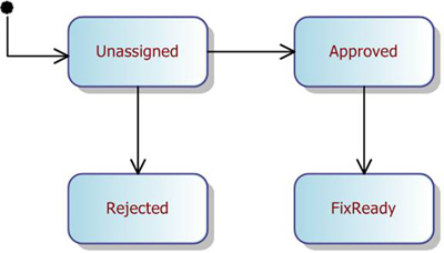
There’s room for potential confusion here when we’re talking about “users.” Dave is not an end user of the Issue Tracking applications, but he is a user of the DSL—it helps him write those applications. Table 2-1 summarizes the terms we will use for these roles.
Table 2-1. Terminology—Roles and Phases
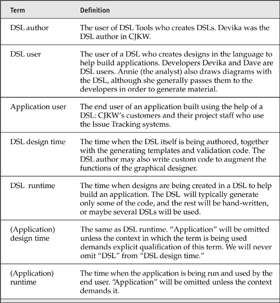
Figure 2-4 provides an overview of the process. It’s worth taking a moment to reflect on the different stages and the things that can be done there, since it is quite easy to get the different levels mixed up.4 In authoring a DSL, we use a designer that creates the DSL definition. From this definition, code is generated for the tools that will edit and process instances of the DSL. We can write extra code that enhances the generated designer.
Figure 2-4. Authoring and usage roles
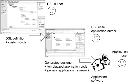
In using a DSL, we are also using a designer, and it can also be used to generate code. The code this time is part of an application. Again, we are likely to hand-write code to augment the generated material.
Evolving the DSLs
Developing the DSL and the executing framework is an incremental process. As more target systems are created, more areas of variation will be identified; some of these will vary often enough to be worth generating from a model. In some cases, the new variation might be added to an existing DSL. For example, some customers require that the set of issue fields that must be completed depends on the issue’s state. To accommodate this, CJKW finds the existing code in which the transition to a next state is committed. To meet the new requirement, this code must be augmented to check that the required fields are filled. Once again the existing source file is extracted into a text template, and the relevant parts are replaced by script that reads the model. A RequiredFields list is added to IssueState for this purpose. The generator is written so that if the RequiredFields list is empty, the generated code looks just as it would have before—so that older models written before this enhancement still work just as they used to.
This scenario illustrates how a body of source code can progressively be brought under a generative regime, minimizing the upfront investment where there is a perceived risk or uncertainty about the design of the DSL or generating templates. Set against this is the cost of frequent small migrations, in particular, writing code to accommodate older models.
Interpretive Architectures
The code that CJKW has been writing depends on an existing framework, so it’s not necessary to create one from scratch. However, the firm eventually gets a customer who wants to run several projects in the same database, each with its own different set of state transitions, and it must be possible to create new projects while the system is running. After some discussion, it is decided that the best way forward is to move the model into the database so that it can be interpreted at runtime. The old generated state menu code will be replaced by a generic routine that reads the state options from a new state transition table; rather than generating code, the DSL model will be used to update the transition table. (One convenient way to do that is to generate a script, so we might still use the text template technology.)
Tip: Generate, then interpret
In general, interpretation requires more substantial change to the existing code, and additional effort to manage the relationship between the model on the DSL user’s screen and its internal representation. When devising an incremental development plan, it is therefore worth considering generating the model to code in the early stages, even if it is to be moved inside the application later on. Conversely, where you are generating a large quantity of code, there may be an advantage in replacing some of it with more generic code parameterized at runtime. (The DSL Toolkit itself exhibits this progression over its history. Early on, a great deal of code was generated from the DSL definition; in later releases, the generated portion was much slimmer.)
Creating a DSL in Visual Studio
In the previous section, we saw the overall process by which a DSL is designed and used. We’ll have more to say about that in Chapter 11.
But now let’s look at exactly what steps the developers have to perform with Visual Studio in order to achieve what we’ve seen. (If you have your own installation of Visual Studio SDK, which contains the DSL Tools, you might like to follow along.)
Creating a DSL Authoring Solution in Visual Studio
The “New Project” dialog in Visual Studio provides a variety of skeleton projects and solutions, and—if you’ve installed the Visual Studio SDK—under “Extensibility,” you’ll find “Domain-Specific Language Designer.” This template creates a “solution”—a collection of projects—and doesn’t give you the option of adding a project into an existing solution. If you want to combine a DSL with another application, you need to create it first and then do some copying later on. (It is in any case better to get the DSL working first.) The dialog takes you to a wizard that asks you details of the DSL you want to create.
The first wizard page (Figure 2-5) provides a set of starting languages on which to base your DSL. Each of them provides a DSL with a fully functioning designer, though without any code generation.
The language templates5 provided (currently) are
Figure 2-5. The DSL Designer Wizard, showing a list of starting languages on which to base the new language

• Minimal. Just enough to show one type of box and one type of line.
• Components. Boxes with ports—that is, small boxes on the boundaries of the bigger ones.
• Classes. Similar to UML class diagrams. The boxes are compartment shapes, which display rows of text.
• Task Flows. Similar to UML activity diagrams. Boxes can be situated within swimlanes.
Tip: Choosing a DSL template
Although you can use one of the DSL solution templates just as it comes, the idea is that you choose the one with the features closest to the DSL you want to build, and you edit it. It isn’t crucial which one you choose—you’ll just have to do more or less editing to achieve what you want.
In addition to these language templates, the Visual Studio SDK comes with a samples browser within which several DSL examples can be found. It’s worth taking a look at these, as they demonstrate a variety of techniques for building interesting designers on the templates. (Look under the VS SDK entry under the Windows “Start” menu.)
Devika chose the Minimal language as a basis for the Issue State language. She might have chosen the Task Flows solution, but she knows that she would have to start by deleting the bits that display the swimlanes, and she reckons it might be quicker just to adapt the Minimal solution.
In the later pages of the DSL creation wizard, she specifies the name of the language and the namespace of the source code for the designer and generation tools. She also specifies the filename extension “.iss” that will be used for files containing Issue State models.
The wizard creates two projects containing quite a lot of files. Prominent on the screen once the creation has finished is the DSL definition of the Minimal language (Figure 2-6).
Nearly all the code in the other files in the two projects is generated from the DSL definition. When Devika modifies the language to change it from the minimal DSL into the Issue State DSL, she will do most of her work on the DSL definition.
The code in these projects (which we’ll look at in more detail in the final section of this chapter) defines three main things:
- The Issue State designer (or whatever language we’re defining)—the editor that DSL users will use to draw Issue State models.
- Code generators—which will take Issue State models and text templates (of the kind we saw in “Driving the Framework from the DSL” earlier in this chapter).
- A serializer, designed to save Issue State models as .
issfiles and load them again. The serializer is used in the designer and in the code generator, and can be used in any separate applications the DSL author chooses to write.
The DSL author can modify any of these functions by adding C# code, usually in small amounts—for example, to add menu commands or validation constraints to the editor, or to change the way models are serialized to file (Chapter 6) or the way in which text templates are interpreted and code generated (Chapter 8).
Trying Out the DSL Solution
Before adapting the language, Devika decides to try out the solution, and so presses the F5 key. (In Visual Studio, this builds the solution and runs it in debugging mode. It is equivalent to the “Debug>Start Debugging” menu command.)
F5 normally has the effect of starting up the application you are designing—perhaps a desktop application in a window or a command line application in the console. But in this case, the users of the DSL are developers—Devika herself, Dave, and her other colleagues—who are going to be building applications with the help of the DSL. They will be viewing the DSL in a designer (graphical editor) that runs within Visual Studio. On pressing F5, therefore, what appears is another instance of Visual Studio, initialized to display a sample of the DSL. In fact, this behavior is common to many Visual Studio SDK examples and templates, allowing you to design enhancements to Visual Studio without fear of causing problems.
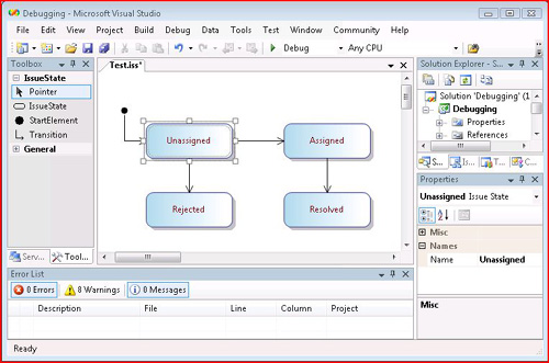
The new instance of Visual Studio (Figure 2-7) opens on a small sample project called Debugging, and within that, opens a file called Sample.iss. This was generated by the DSL creation wizard—you can see it in the file system alongside the main generated project folders.
Figure 2-7. The designer for the Minimal language

Figure 2-7 shows the basis of the tool that Devika and her colleagues will be able to use—once she has completed her work on it.
• The largest window is the design surface, the main presentation of a DSL instance. Devika will have to edit the DSL definition (back in the main Visual Studio) in order to add, for example, the definition of the Issue State language’s start element, the black dot that flags the start state. When the DSL is all working and deployed, DSL users will draw their Issue State diagrams here.
• On the left is the toolbox. To make a new element, you drag from the tool onto the diagram; to make a new connector, you click the relevant tool, click the source element on the diagram and then the target. Devika will have to edit the DSL definition to change the names of the tools to “Issue State” and “Transition,” and add a tool called “Start Marker.”
• On the right is the model explorer. This shows a tree presentation of the model (that is, the DSL instance). It shows the elements and their embedding relationships. In some DSLs (depending on their design), there are elements that do not appear in the main design surface but will always appear in the model explorer.
• In a separate tab under the model explorer is the usual solution explorer, showing the Debugging project containing the sample file. Devika will change the name of the project to “IssueStates.” When it is deployed, copies of this project will run alongside the other code of Issue Tracking applications. She will add text template files that will read the user’s DSL instance and create code that forms part of the Issue Tracking application.
• Below that is the properties window. When any element is selected in the main diagram or the model explorer, its properties are displayed here and can usually be edited. Some properties, such as an element’s name, are displayed and may be edited directly in the shape. Clicking in the main part of the diagram shows the domain properties of the root element of the model; clicking on a shape or connector shows the domain properties of its corresponding domain class instance or domain relationship link.
(The arrangement of these windows is variable. If any of your windows seems to be missing, find it under the “View” menu; some of them can be found under the “Other Windows” submenu.)
Defining the DSL
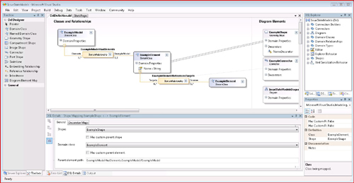
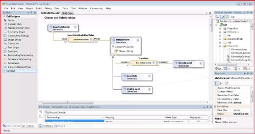
Devika is now ready to author her own DSL. She closes the experimental instance of Visual Studio and returns to the DSL authoring solution. If it isn’t already open, she opens DslDefinition.dsl in the Dsl project. This launches the DSL designer (Figure 2-6). The DSL designer looks not unlike the designer of the Minimal language or any other specific DSL. This is because it was “bootstrapped”—designed using itself.
The main window contains two swimlanes or columns: on the left, the domain model— that is, the domain classes and relationships, and on the right, the shapes and connectors that represent them on screen. The names of all of these items can be edited; new ones can be created using the tools in the toolbox. Unlike most designers created with the DSL Tools, this one maintains a strict tree-like presentation of the elements and their relationships. By right-clicking on the domain classes, you find commands for reordering the tree.
Devika edits names of the domain classes, shape, connector, and diagram, so that they become like those of Figure 2-8; then she edits the role names (the labels on the two arms of each relationship), and finally, she edits the relationship names. Each of these can be edited directly in the diagram, except for the role names.
Figure 2-8. DSL after editing names
Tip: To change the label appearing on a relationship role, edit the Name of the opposite role
For example, to change “Targets” appearing on the left of the ExampleElementReferencesTargets relationship (Figure 2-6), select the opposite role (labeled Sources) and in the properties window, change the Name property from Target to Successor (in the singular). The label on the left-hand role will automatically change to Successors (plural). This makes perfect sense—see Chapter 3 for details.
The final step is to change the names of the tools that will appear in the toolbox. These are not represented in the main diagram of the DSL definition—look instead at the DSL explorer; the tool definitions can be found underneath the Editor node. Their names can be edited in the properties window together with the tooltips and captions that are displayed to users.
Generating the Code for the Designer
Code for the designer of this DSL is generated from the DSL definition file. To make that happen, go to the solution explorer (in the main Visual Studio) and click the “Transform All Templates” button in its header (Figure 2-9). All of the code files will be regenerated.
Figure 2-9. Solution explorer with “Transform All Templates” button
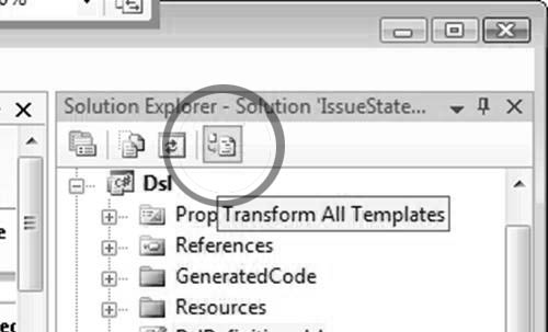
Tip: After editing the DSL definition, always click “Transform All Templates”
The “GeneratedCode” folders contain a number of text template files with the extension .tt. Each of these has a subsidiary file that is the generated result. In the solution explorer, click the “[+]” to see it. The generated files include both C# and resource files. Don’t edit the generated files!
After regenerating the code, Devika presses F5 to run the experimental VS on the Debugging project. The sample file she first looked at can no longer be read—she has changed the definition of the language, so that the old ExampleElement instances of the Minimal language are ignored by the deserializer.
Instead, she creates a new file in the Debugging project (using the “Add new item...” menu command). The file opens, and she can create elements and relationships in it. In fact, it’s just like the Minimal language—but the names have changed (Figure 2-10).
Figure 2-10. Issue State designer—first prototype

Adding to the DSL
With the encouragement of a working tool, Devika is enthusiastic to improve the DSL. She again stops the experimental Visual Studio, returning to the DSL definition.
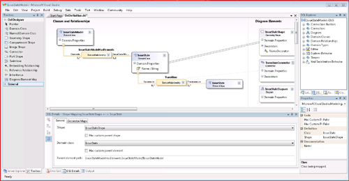
The start element—the black dot that marks the starting state—is still missing from the DSL. Like IssueStates, StartElements can be connected to IssueStates, so Devika reasons that they should be derived from a common abstract base class. Adding some domain classes and a shape, redefining the shape maps, and setting the base class’s Inheritance property to abstract (in the properties window), she ends up with the DSL definition of Figure 2-11.
Figure 2-11. StartElement and IssueState have an abstract base class
For the StartShape, she uses a geometry shape and sets its “geometry” property to Circle. She also changes the default size and color properties of the other shape and connector.
A new tool is required for the StartShape that can be added under the Editor node in the DSL explorer window. Devika tries to save the DSL definition at this point but gets an error complaining that no icon has been defined for the new tool. Using the solution explorer, she goes into the Resources folder in the Dsl project and copies one of the bitmap files there. After renaming the copy to StartElementTool.bmp, she opens it and edits the picture so that it contains a circle. While there, she edits the other tool images as well.
After she clicks “Transform All Templates” and presses F5, she is now able to draw the state chart she’s aiming for (Figure 2-12).
Figure 2-12. DSL with StartElement and improved tool icons and arrows
Constraints
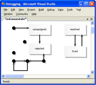
However, she also finds she can draw many diagrams that would be difficult to assign a clear meaning to, and to generate code from diagrams with multiple start elements, start elements with multiple lines or no lines emerging, arrows targeting start elements, and disconnected groups of states (Figure 2-13).
Figure 2-13. Invalid state model
Devika considers two solutions to this.
One tactic is to move the Transition relationship so that it only applies between States, and to define a separate relationship from StartElement to State, with a restricted multiplicity (Figure 2-14). With a little modification to the Tool definitions, the same connector tool can be used to create either type of relationship, depending on whether the user drags from a start element or from a state. And by making the two relationships derive from a common base relationship, the same Connector class can be used to represent both of them on screen. That way, the two relationships appear to the DSL user to be one, but at the same time he or she cannot make multiple connections from a StartElement, nor any connections to it. This is an example of a hard constraint that prevents the user from ever breaking the rule.
Figure 2-14. Issue State domain model with inheritance between relationships
An alternative, more applicable to the sins of disconnected loops and multiple start elements, is the validation constraint. This is a fragment of C# written by the DSL author that checks for invalid configurations of objects and complains about them to the user when he or she tries to save the file. It allows the user illegal configurations while editing is in progress as long as everything is correct in the end.
To create a validation constraint, Devika creates a new C# file in a separate folder alongside the generated code. The file will contain partial class definitions, adding the validation methods into the generated classes. You can see the results in Chapter 7.
Customizing the Explorer Window
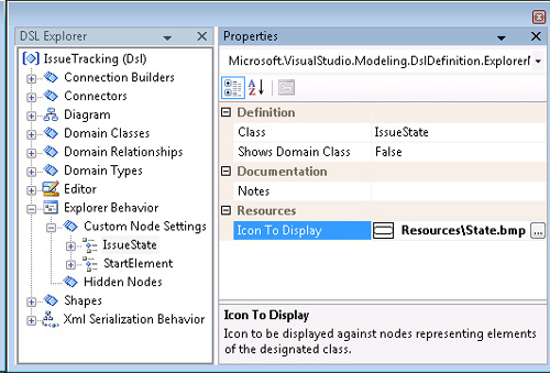
Devika now wants to customize the look and feel of the explorer. Specifically, she wants to replace the domain class name, which appears in brackets by default, with icons that indicate the kind of element involved. To achieve this, she adds two “Custom Node Settings” elements under the “Explorer Behavior” node in the DSL explorer, as shown in Figure 2-15.
Figure 2-15. Explorer behavior definition
When she’s done, she regenerates and presses F5 as usual. She opens an existing model and sees the explorer as expected (Figure 2-16).
Figure 2-16. Result of customizing explorer

The presentation of elements in the explorer is described in Chapter 4. Adding and deleting elements through the explorer is handled in Chapter 5.
Customizing the Properties Window
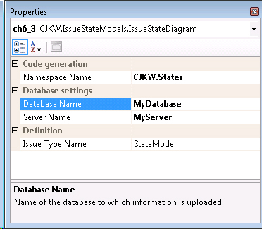
Next, Devika wants to customize the properties window. Specifically, she wants to categorize the properties and give them appropriate descriptions. She does this by changing settings on domain properties and roles. Figure 2-17 shows the settings for the DatabaseName property on IssueStateModel. Figure 2-18 shows the result of these changes when displaying properties in the Issue State designer.
Figure 2-17. Settings on a domain property

Figure 2-18. Result of changing settings on a domain property
Custom Code for the Designers
The DSL definition allows us to specify a wide variety of behaviors in a generated designer and its accompanying serializers and generators. An even wider range is feasible by augmenting the generated classes with handwritten code, and we will see several examples in the chapters that follow. In fact, most of the chapters begin by showing you how to define a range of behaviors in the DSL definition and how to gradually move on to more specialized customizations that require some C#. One typical use for custom code is to add context menu commands to perform some action directly from the designer, a technique described in Chapter 10.
Like validation constraints, custom code takes the form of methods and classes that are integrated with the generated code. Heavy use is made of partial class definitions—the facility for splitting the code of a class between more than one source file. Chapter 10 surveys the full range of available customization techniques.
Serialization Format of the DSL File
Let’s take a look at the saved XML form of the model file of Figure 2-12:
<?xml version="1.0" encoding="utf-8"?>
<issueStateModel dslVersion="1.0.0.0" name="StateModel"
xmlns="http://schemas.cjkw.com/IssueStateModels" >
<states>
<issueState name="Unassigned">
<successors>
<issueStateMoniker name="/StateModel/Assigned" />
<issueStateMoniker name="/StateModel/Rejected" />
</successors>
</issueState>
<issueState name="Resolved" />
<issueState name="Assigned">
<successors>
<issueStateMoniker name="/StateModel/Resolved" />
</successors>
</issueState>
<issueState name="Rejected" />
<startElement name="StartElement1">
<issueState>
<issueStateMoniker name="/StateModel/Unassigned" />
</issueState>
</startElement>
</states>
</issueStateModel>
Notice that all the elements are represented very simply, using lowercase versions of the names in the DSL definition. Links are expressed in a path syntax using the names of the elements. This makes the file very easy to read and easy to write processing software for. Like everything else, if required, the format can be changed quite substantially within the DSL definition, and can be changed more radically by writing custom code.
Driving Applications from the DSL
The purpose of CJKW’s Issue State language is to allow DSL users—the authors of Issue Tracking systems—to define the states and transitions that can be made within an Issue Tracking application.
Generative Application
Devika’s initial plan—though as we’ll see, the team improves on it—is to generate part of the application’s user interface code from the DSL. She envisages that when Dave is writing the code for yet another Issue Tracking system, the Visual Studio project that contains the user interface code will include an Issue State file and one or more text template files that will generate the user interface code. When Dave is actually using the DSL, it will be fully installed in his main VS hive, but for test purposes, Devika works in the experimental VS.
She starts the experimental VS either by pressing F5 in the main project or by using the “Start VS in Experimental Hive” command in the VS SDK section of the Windows Start menu. Now she opens the existing code of an Issue Tracking application and finds the file containing the user interface code. This is the one she wants to depend on the state diagram.
First she copies an Issue State file into the application’s project.
Then she proceeds to knock holes in the application code, as we saw earlier, replacing fixed pieces of code with the mixture of generated code and DSL-querying code that we saw in “Driving the Framework from the DSL” earlier in this chapter. To complete the transformation to a text template, she adds some essential header information adapted from the sample .tt files in the Debugging project and changes the file’s extension to .tt.
This automatically creates a subsidiary file containing the generated code. Editing the .tt file will update the subsidiary .cs file.
Building and running the Issue Tracking application, Devika is satisfied to see that when an issue log is displayed, the state drop-down menu does offer just the next states her state model dictates.
If necessary, other files in the application can be given the same treatment, progressively turning them into template files and generating their code, which is dependent on the DSL. Whole projects full of files can be generated from a single DSL file—the DSL designer solution is a good demonstration of this.
If the state model is changed, all of the files can be regenerated, using—guess what?—the “Transform All Templates” button. This time, we’re using it not to generate the code for the language but to generate a target application from an instance of that language.
Interpretive Application
Devika’s solution is shown to customers, who like it. But reviewing Devika’s prototype, Annie (the analyst) objects to the design. She points out that part of the way through many projects, the managers want to redefine the states and transitions their issues go through. It won’t really be acceptable to regenerate and rebuild the Issue Tracking application for this purpose.
Archie (the software architect) suggests a solution. The Issue Tracking application should be rewritten to be more generic, storing the set of allowed states and transitions in the issues database itself. The DSL will be used to set these tables. As well as making the application dynamically configurable, the same software can now be used for many applications. In theory, there could be a small performance penalty for this more interpretive approach, but the negative effect will be tiny in this case and well worth it. The other issue is of course the extra work needed to refactor the application—making it store the state model and interpret it is a substantially bigger job than punching template holes in the existing code.
Devika is a bit disappointed that her generative solution wasn’t acceptable, but the others point out that the DSL design itself need not be changed, and that the generative approach allowed her to prototype and demonstrate the whole approach rapidly, before investing in the more expensive interpretive solution.
The team considers two methods of loading the DSL’s state model into the database. One is in a sense generative again. We write a text template that generates an SQL script that sets the state and transition records. After generating the script, it can be handed to the database administrator to run at an appropriate time.
The other method is more direct and involves writing some custom code for the designer. A menu command is added that logs onto the Issue Tracking database and runs the necessary SQL commands directly. The DSL user will draw the Issue State model and call up the menu directly on the design surface; the effects should be immediately visible in the application.
Deployment
Once the DSL and the framework it generates have been developed, they can be packaged in an installer and distributed in the form of a standard .msi (Windows installer) file. The installer can include
• The designer, serialization, and text template processor components for the DSL.
• An item template for Visual Studio’s “Add new item” command, allowing the DSL user to create a new instance file of the DSL in a Visual Studio project.
• A project template for the “New Project” command, allowing the DSL user to create a new instance of a project in which the DSL is used—including all the code generation templates for the application in hand.
• Compiled assemblies that are required for the generated application. Typically, the generated parts of an application can be separated from the unchanging generic parts; the latter can be compiled and distributed in that form rather than as source.
• Readme and license agreement files that should be displayed when the installer is run.
The DSL Tools make it easy to create an installer. A “Domain-Specific Language Setup” project template is in the same location as the “Domain-Specific Language Designer” template. Devika uses this to add a setup project to her solution, which, when built, constructs the .msi file. Devika is able to customize what’s included in the installer as well as customize the UI that gets displayed when the .msi file is executed, just by editing an XML file (it’s actually a DSL file with an XML syntax), and then reprocessing the .tt files in the Setup project. See Chapter 9 for details.
Devika’s colleague Dave has a standard edition of Visual Studio, without Visual Studio SDK. The installer automatically begins by installing the DSL Tools runtime and then installs the DSL itself. He can now create, edit, and use instances of the Issue State language even though he cannot author them.
A Second DSL: The Project Definition DSL
One useful aspect of the Issue State DSL is that a state model can be drawn offline and uploaded to the application after it has been discussed. Other aspects of the Issue Tracking application’s administration remain uncomfortably immediate, however. For example, an administrator can set up new projects in the database and new categories of work to which issues can be assigned, but the effect is immediate, with no possibility for offline consideration.
Using a similar incremental process to the Issue State DSL, Archie (the architect) and Devika (the lead developer) create a new DSL. The resulting designer is shown in Figure 2-19.
Figure 2-19. Issue Project designer
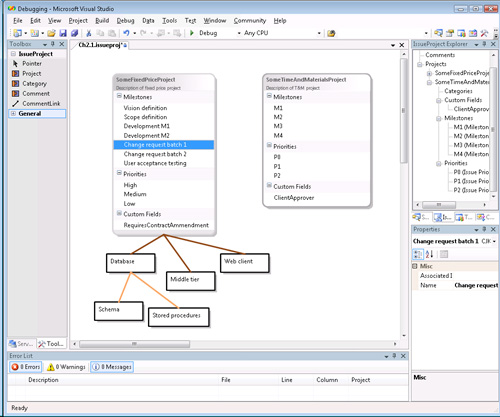
The new designer drives the issue database in much the same way as the Issue State DSL.
An interesting aspect of this is that we now have more than one DSL in use to drive different aspects of the same application.
Architecture of the DSL Tools
A new DSL Tools solution in Visual Studio contains two projects, Dsl and DslPackage. Dsl provides code that defines the DSL in terms of the behavior of the generated designer, how it is serialized, and how transformations work; DslPackage provides coupling to Visual Studio so that instances of the DSL can be opened and saved as documents.
The Generated Code
Most of the content in both projects resides in the GeneratedCode folders and is generated from DslDefinition.dsl. While it’s instructive to look at the content of these folders, it is never useful to edit them, as the edits will be lost the next time you click the “Transform All Templates” button. When you write custom code for validation constraints or to augment the functions of the generated designer, it should be written in separate files in a “Custom Code” folder.
Looking into the GeneratedCode folders using the solution explorer, the text template files (.tt) are immediately visible; to reveal the generated files, click the “[+].” Opening a typical template file, we see that there is very little code aside from a reference to the DSL definition file and an include directive:
<#@ Dsl processor="DslDirectiveProcessor"
requires="fileName="..DslDefinition.dsl'" #>
<#@ include file=îDslConnectors.ttî #>
The included files are to be found within your Visual Studio SDK installation directory, under VisualStudioIntegrationToolsDSLToolsTextTemplates.
Most of the customizations you may wish to perform can be done by adding to the generated code—see Chapter 10 for details. In the rare case in which you need to change the generated code, replace the @include directive in the project’s text template file with the text from the included standard template, and then edit that.
DSL Tools Architectural Layers
The generated code is concerned with the variations that make your DSL different from others. The generic features common to all DSLs are provided in a number of compiled assemblies that are installed as part of the DSL Tools.
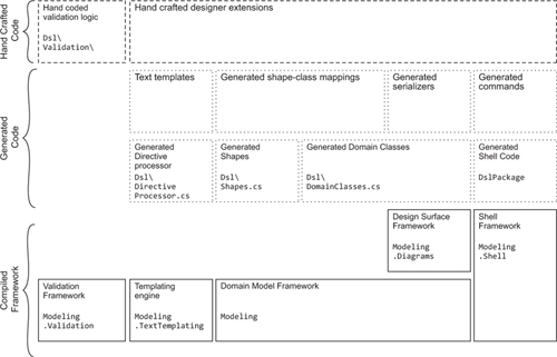
There are thus three major layers in the architecture of a DSL implementation: the compiled framework, the code generated from the DSL definition, and hand-written code. The major parts are shown in Figure 2-20.
Figure 2-20. Architecture of the DSL Tools
The Framework Assemblies
• Microsoft.VisualStudio.Modeling—The domain model framework is at the core of the system, managing model elements and links—instances of domain classes and domain relationships, which were introduced in Chapter 1 and are covered in detail in Chapter 3. It supports transactions, including undo and redo as well as the propagation of changes using rules and events, for example, to keep the screen presentation synchronized with the internal model.
• Microsoft.VisualStudio.Modeling.Diagrams—The design surface framework is built on top of the domain model framework and deals with the graphical notation by handling the display of elements on the design surface such as diagrams, shapes, connectors, decorators, and so on. These elements are also model elements, so the services of the domain model framework can be exploited for their management. The presentation aspect of a designer, which exploits this framework, is described in Chapter 4.
• Microsoft.VisualStudio.Modeling.Validation—The validation framework handles the execution of validation methods over model elements and links, and then the creation of error objects when validation fails. This interfaces with the shell framework to post messages in the errors window of Visual Studio. The use of this framework is described in Chapter 7.
• Microsoft.VisualStudio.Modeling.TextTemplating—The templating engine is used to execute text templates for the generation of code and other artifacts. It is an independent component that can be used to execute templates that obtain their input from sources other than DSLs. The use of the templating engine is described in Chapter 8.
• Microsoft.VisualStudio.Modeling.Shell—The modeling shell manages the hosting of the designer in Visual Studio, in particular, dealing with tools, menu commands, and the opening and closing of files.
Content of the DSL Project
The compiled code assembly built by the Dsl project (Figure 2-21) defines the DSL. A stand-alone application can use this assembly to load and manipulate DSL instance files, though without the benefit of the graphical user interface.
Figure 2-21. Files in the Dsl project
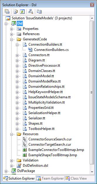
• DslDefinition.dsl—The file from which all the generated code is derived.
• DslDefinition.dsl.diagram—Every DSL instance is stored in a pair of files: one containing the essential information about the domain class instances and relationships, and the other containing the layout of the diagram. If the diagram file is lost, the user needs to rearrange the material on the screen, but no important information is lost. The DSL definition is like any other DSL in this respect.
• Resources folder—The images used in the toolbox for cursors and on some shapes. The images may generally be in any of several formats, including bitmap (bmp) and JPEG. The files that should appear here are determined by the content of the DSL definition. For example, if you define a new Tool in the DSL definition, it must have an icon to represent it in the toolbox. You provide a name for the file and then supply it in the Resources folder.
• PropertiesAssemblyInfo.cs—Version information that finds its way into the compiled code for your DSL. The entries are derived from the values you supplied to the wizard when you created the DSL.
• Dsl.csproj—The project file isn’t explicitly shown in the folder, but its content is accessible by right-clicking the Dsl project node and choosing “Properties.” The assembly name and default namespace are derived from values you supplied to the DSL creation wizard.
Several of the files in the GeneratedCode folder correspond to the main sections of the DSL definition as seen in the DSL explorer:
• DomainClasses.cs—A class (or two) for each of the domain classes defined in the DSL definition. There are regions in each class handling each domain property, each role (that is, participation in a relationship), and in some cases a handler handling “merges”—linking of one object to another. Each class also contains a nested property handler class for each domain property. (See Chapters 3 and 5 for details.)
• DomainRelationships.cs—A class for each domain relationship. All the same code as domain classes, plus handlers for the linkage to each end of the relationship.
• DomainModel.cs—A class representing the model as a whole (not the same as the root class of the model). It provides mostly reflective information about the other domain classes.
• Shapes.cs, Connectors.cs—Implementations of the graphical aspects of the DSL definition. Contain quite a lot of code that can be overridden or augmented to customize the interactive behavior of the generated designer. (See Chapter 4.)
• Diagram.cs—Includes code for updating the diagram content when the model changes.
• ConnectionBuilders.cs—Implements the detailed behavior of connection tools. (See Chapter 5 for details.)
• ToolboxHelper.cs—Code called when Visual Studio sets up its toolbox, which defines the tools for this DSL. This code is generated from the “EditorTools” node in the DSL explorer. (See Chapter 5.)
• Serializer.cs, SerializationHelper.cs—Define how instances of the DSL are saved to files. Generated from the Xml Serialization Behavior section of the DSL definition. (See Chapter 6.)
• DirectiveProcessor.cs—Defines parameters to the template processing engine that allow instances of the DSL to be referenced by text templates. (See Chapter 8.)
• LanguageSchema.xsd—The XML schema definition for the language.
• MultiplicityValidation.cs—Where the DSL definition specifies that the minimum multiplicity of a relationship role is 1, this code checks that the DSL user has indeed created a link, as part of the validation checks on saving the file.
• DomainModelResx.resx—A resources file containing strings and image references used in your DSL. (See Chapter 4.)
Content of the DslPackage Project
The assembly generated by this project (Figure 2-22) is concerned with managing DSL instances as Visual Studio documents. Many of the files are standard for packages defined using the Visual Studio SDK and are discussed in the VS SDK help.
Figure 2-22. The DslPackage folder

• Commands.ctc—Modify this file to define menu commands in the standard Visual Studio command table syntax. (See Chapter 10.)
• GeneratedCommand.h—Text that is included by Commands.ctc that defines the standard menu commands for the DSL that appear when you right-click on the diagram—for example, to run validation checks.
• CommandSet.cs—Code for the standard commands for the DSL.
• Constants.cs—The file extension of this DSL, the version number, the Globally Unique IDs (Guids) of the designer package, and so on.
• Package.cs—Run by Visual Studio when setting up its toolbox and menus, to register menu commands. Notice the class attributes, which control the registration of the package, tools, explorer, and the mapping of the filename extension to this package.
• EditorFactory.cs—Code to start up the designer for the DSL when a file is opened.
• DocData.cs—Code managing the loading and saving of a DSL file within Visual Studio.
• DocView.cs—Code managing the presentation of a DSL instance in a designer window.
• ModelExplorer.cs—Code for the explorer specific to this DSL.
Summary
This chapter has examined a scenario in which a company used DSL Tools and provided an overview of their application. Several points have been made:
• A DSL allows you to quickly and reliably produce multiple variants of a piece of software and to make changes when necessary.
• A DSL and the framework that executes it (or uses it as input) are developed together, preferably in gradual steps to minimize risk.
• In some cases, the system may graduate from a generative toward an interpretive framework, allowing more runtime flexibility.
• A wide variety of functionality may be specified in the DSL definition and may be extended even further by augmenting the generated code with hand-written code. Hand-written code is used particularly in the definition of validation constraints.
• To understand the DSL Tools and their use, it is important to distinguish between the roles of DSL author, DSL user, and the user of the application created with the help of the DSL.
The chapters that follow treat in more detail all the features touched on briefly here. The final chapter discusses in more depth the process for designing a DSL in the broader context of the software development process.