11. Designing a DSL
Introduction
In Chapter 2, we discussed how a DSL is developed incrementally and bottom-up. You begin with specific application code and gradually parameterize it. First turn your existing code into a set of templates—so that if they were not modified, they would just generate the original code. Then gradually replace pieces of the templates by template expressions; the DSL develops alongside, as the means to express these statements’ parameters.
We contrasted this with a top-down approach that begins by considering the domain as a collection of interrelated concepts—those represented in the DSL’s domain model. That approach has a number of potential advantages. It gets much more quickly and directly to a substantial DSL; it tends to produce a more self-consistent and complete result; and it tends to ensure that variations are expressed in terms of requirements rather than implementation, so that incidental variations in implementation are factored out. However, we also observed a problem with top-down—that it often leads to impractical implementations if not combined with bottom up regularly. We concluded that, in practice, it is effective to alternate between top-down and bottom-up techniques, working incrementally to avoid the risk of a big upfront investment but occasionally standing back to check for consistency.
We stepped through a small slice of the development of the CJKW Issue Tracking DSLs, framework, and code generators, and we touched on many of these points but did not explore the process in any depth. That’s the purpose of this chapter. Specifically, we discuss a range of techniques and options for:
• Identifying variability and discovering DSLs—A DSL is about the bits that vary, while your framework embodies the patterns of your architecture.
• Developing the domain model to capture points of variability.
• Defining the notation, using a familiar notation or notational conventions where applicable.
• Developing validation constraints—Identify dependencies between properties and spot mandatory or prohibited loops in your snapshots.
• Developing and evolving the framework—Understand the architecture of the code that your DSL targets, and encode that in a framework.
• Testing the DSL, the validation constraints and rules, generators and commands, and generated code.
• Evolving and migrating a DSL—Ensure old models can be used with new versions of the DSL.
• Recognizing a good DSL—Scope, minimality, familiar notations, moderate redundancy, good use of the syntactic space, using the users’ terms.
Identifying Variability
CJKW has two mingled motivations for developing a generic framework, of which DSLs may be a part. (Your own emphasis may be on one or the other.) The first motivation is to maintain a product line of multiple similar products—all of their customers want Issue Tracking systems, but with different features. The second motivation is to facilitate variation through time of each product—each customer wants to be able to introduce new features at short notice. The first represents the ideal; go to customers with the product, the Issue Tracking system, and a list of features that customers can choose from to configure the product to suit their needs. CJKW would input the customer choices into the product factory, which creates the Issue Tracking system tailored to a specific customer’s requirements. The second motivation, however, represents reality; the customer will always want to adapt the system to meet new requirements once it’s been delivered, and these requirements are bound to include features that weren’t predicted when setting up the original product line.
Fortunately, both problems can be mitigated by the same basic approach: separating out the parts that vary from the parts that remain constant, thereby making changes easier. And where the changeable parts form complex structures, DSLs may be created to express their instances.
Bottom-Up or Top-Down?
Identifying variability can be like performing a balancing act. If you follow agile programming principles to the letter, you should never create features based on future prediction (on the assumption that it is impossible to get right); you should instead wait until the actual need arises and then refactor accordingly. This tends toward a bottom-up way of working. On the other hand, you can accommodate all the variations you have seen so far, but then the next thing that comes along requires some change deep in what you had thought was the invariant part of the system. So some awareness of future needs may mean you can plan your refactoring in order to help with planning of resources and to ensure a smoother transition when major rearchitecture is required. An awareness of possible future needs tends toward a top-down way of working.
To date, CJKW’s clients have required that different projects have different sorts of issue, with different fields and different sequences of states, but none has yet needed two sorts of issue within the same project. To make issue-types distinct from projects would require substantial work on the database schemas and surrounding code. The one client who would have it was able to accept that one real-world project would use two database projects, one for each sort of issue. Some team members have argued for doing the necessary refactoring upfront, but the cost is assessed as being fairly high, and to do all the refactoring now would pull resources away from directly revenue-earning work. Instead, a plan is drawn up to phase in the refactoring over time to meet the predicted needs of future business; it is expected that there’ll be many more clients who have the same need, and by refactoring the product line to include this feature, they will be able to generate more business and be more competitive in the market. Although the plan is informed by the needs of the first client who wanted this capability, inevitably it has required a top-down analysis of the likely requirements in this area and some upfront design of the architecture of the refactored framework.
Feature Trees
One technique for thinking about and capturing variability top-down is feature trees. A feature tree1 is a presentation of a set of requirements, some of which are optional. Because options are often interdependent, they can be presented as a tree. As a configuration tool, you have probably seen them in software installer wizards, under the “Custom Install” heading. (For example, the Windows Installer—you choose the features you require. OK, so you want IIS; do you want FTP, or Web Service? If you want Web Service, do you need a scripts directory? And so on.) As analytical tools, they are useful for setting out the options your clients have or could have.
Figure 11-1 is part of the feature tree CJKW creates for its Issue Tracking product line. Most items are optional—you make a set of selections to define a particular product from the line. A child item can be selected only if its parent is selected, together with additional dependencies shown by the dashed arrows. “X” marks mutual exclusion between choices.

For example, as a customer, I might decide that I don’t need multiple projects, but I do need multiple users, although access control is not required. I’ll have an audit trail, but must accept that because I haven’t chosen access control I can’t restrict the audit trail to managers.
The tree notionally includes every feature in the requirements document; some of them may turn out not to be optional after all. After some discussion, CJKW decides that Multiple Projects is a non-optional feature of every installation; this saves development effort, and in practice loses little flexibility—customers who want “single list of issues” need only create one project.
Development tasks can be mapped to the nodes in the tree that they enable. Development effort is required both for features and optional or XOR nodes. One task links each issue to a milestone, but more effort is required to make that optional per installation, and yet more is needed to make it optional per project.
A feature tree is about requirements, rather than design; each feature describes something that can be seen by the client of the system. In their first few customer-specific systems, CJKW’s design choices evolved somewhat as the team gained experience. Many of the variations are about changes in design choices rather than changes in requirements—for example, using a list instead of an array at some point. These changes are not included in the feature tree.
Choices may be marked with how often or in what context they may vary—for example, Single/Multiple User—select on Installation; Custom Fields—select per issue type or project; Multiple Types of Issue per Project—currently fixed at false. Each project defines a single type of issue.
Feature trees are not only for features visible to end users. If you are designing something like a generic wizard builder, then your clients are the developers who call your subsystem, and your features are the behavior visible to them at your API.
Feature Trees and DSLs
Feature trees work well for binary or enumerated choices. A feature tree can work more or less directly as a DSL clothed in a suitable syntax. Many installers have feature trees that appear either in the form of expandable trees of checked options or as wizards.
But some variabilities are more complex structures that cannot simply be selected or deselected. Inspecting its feature tree, CJKW’s developers identify that where customers opt for “Sequence of states constrained to a given sequence” and “custom fields definable per project,” the users will need suitable notations for defining the detail of these choices. This is the origin of the two DSLs used in the project.
Developing the Domain Model
In Chapter 2, the Issue State DSL came about by observing that statecharts seemed a good fit with the problem, which was confirmed by the business analyst who was already drawing state diagrams informally when eliciting requirements from customers. Once that basic connection had been observed, the DSL was refined by sitting back and thinking about the domain model and notation as a whole, and by making changes incrementally to the definition (for example, adding properties to domain classes) as dictated by the needs of the code generators.
However, it’s not always that easy. In this section, we describe a more systematic technique for creating the domain model aspect of a DSL. This technique tends to be useful to get you through cases where it’s proving difficult to work out exactly what domain classes, relationships, and domain properties are required. The technique is adapted from a technique proposed in the Catalysis2 approach to object-oriented analysis and design.
Sketch Domain Snapshots
The requirements scenarios describe the domain in words. To help clarify them, it is a very useful whiteboard technique to draw snapshots. A snapshot is an informal drawing showing a collection of elements and links at a particular moment in time. Only some elements and links will be instances of domain classes and relationships in the domain model of a DSL; the domain model can be inferred from them. Others represent instances in a running system generated from models expressed in the DSL; the instances are generated from the instances of the domain classes and relationships defining the DSL. Of course, when you start, you don’t know which are which, and that’s part of the analysis that needs to be done.
Project and Field Snapshots
Let’s focus first on custom field definitions. In the feature tree and scenarios, we identified that a project administrator can determine what fields are available to users who create issues, and that these sets of fields are defined on a per-project basis. So we can draw some example fields associated with a typical project. Each field will have a name and a type. Associated with each project will be some issues; each issue has a description and—among other things—some values for the fields. Each field value associates a value of the correct type with a field and an issue. So the drawing looks like Figure 11-2.
Figure 11-2. Snapshot—custom fields

Notice some of the principles we’ve followed:
• Snapshots. Draw a single instant in time. Illustrate a particular point in a requirement scenario. If there are widely differing configurations of relationships, use more than one snapshot to examine and discuss them.
• Abstract. The nodes and lines here say nothing about how they are implemented in a machine. Keep those questions separate.
• Highlight variability. The bold lines and entities drawn in bold are those that change less often. For example, once a project has been defined, the set of Issue Types allowed to it will change rarely, but issues will be added frequently. Distinguishing different frequencies of variability is the key to identifying which elements and links represent instances of domain classes and relationships.
• Disallowed links. Snapshots are particularly good at illustrating and providing insights about constraints—for example, that an issue’s field values must be for fields belonging to the issue’s own project. To illustrate these constraints clearly, show some disallowed links.
• Sketches. This is a whiteboard or paper exercise. Don’t feel obliged to stick to a “correct” syntax. Feel free to draw smilies, stick figures, houses, and so on instead of ellipses.
• Separate topic areas. Don’t crowd everything onto one diagram. Show different groups of relationships on different drawings.
• Changes. It can be useful to show on the diagram what changes are allowed—especially how relationships may change (see the Issue State snapshot in Figure 11-3).
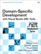
Figure 11-3. Issue Snapshot: Issue State
Issue State Snapshots
Now let’s move on to Issue State. The requirement is to allow an administrator to determine, for each project, the collection of states that an issue can take on, and what transitions are allowed between them. We draw a typical project and some states, as illustrated in Figure 11-3. Each project has an initial state that a new issue must take on, and each state has a set of permitted next states.
We should make some cautionary observations about snapshots. Because they are informal, they don’t pretend to represent exactly or completely everything there is to say about the topic; they’re just an aid to thinking. For example, is there always a single Initial State for each project, or can the project have more than one—from which a user must choose to create an issue? We can’t tell from this snapshot—it might just be that there is only one in this particular illustration.
Tip: Snapshots and filmstrips
Questions such as “How many initial states?” can be answered by producing a collection of snapshots representing the different possibilities (e.g., draw one where there is more than one initial state in a project) and by testing that against scenarios. One way to generate such a collection is to write out user stories and then develop a sequence of snapshots, a filmstrip, to illustrate the conceptual state of the domain at each step. An efficient way of doing this is to produce a single diagram and then use different colors to show the changes between each step—it works very well on the whiteboard and PowerPoint. Once you’ve done this a few times, you may find that you don’t need to physically draw the snapshots—you can construct them in your head, and the user stories are sufficient. However, there are always difficult cases where the only way to sort it out for sure is to commit ink to surface.
Because at this stage the lines on the diagram represent conceptual relationships rather than actual implementation, we can always feel free either to leave off any redundant relationships to avoid clutter or to include redundant information if it makes things more clear. For example, we can see that the Completed state belongs to BigProject because you can follow a chain of transitions from the initial state; in an implementation, we would probably link each state directly to its owner project and record the transitions. Conversely, we have linked each issue both to a project and a state, but we could in theory have left out the project link, since each state belongs to only one project. We’re exploring the scenarios that our DSLs will represent rather than an implementation.
Domain Model from Snapshots
The feature tree helped us identify the two areas where we might use DSLs. We have drawn some snapshots of the domain in typical situations in order to help us understand the real-world relationships that the DSLs will express.
In this step, we separate out parts of the snapshots that are relevant to a particular candidate DSL and create a model of the domain using the DSL Tools Domain Model Designer.
Project Definition Domain Model
The first DSL area covers the definition of fields that issues in a particular project can have. We pick out the less changeable parts of the snapshot—they are the projects and field definitions and their relationship, as shown in Figure 11-4.
Figure 11-4. Inferring a domain model from a snapshot

At this stage, we have to make some distinctions that were unclear from the snapshots. What exactly are the multiplicities for fields in projects? What are the types that a field can have?
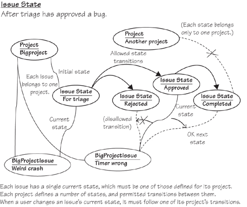
We may also refine and extend the model from the initial sketches. The requirements call for each issue to be assignable to a Category; Categories are defined per project, and each can contain subcategories. We create a new snapshot to look like Figure 11-5.
Figure 11-5. Snapshot—categories and fields

This leads to another draft of the domain model in Figure 11-6. While drafting the model, we decide the domain class name “IssueCategory” will be more explanatory than “Category.”
Figure 11-6. Domain model—categories and fields

Notice how, in the snapshots, we consider objects and relationships outside the scope of the domain model we end up with—here, the instance issues and field values. They are about the meaning of the DSL—in this case, how a model in the language defines structures and constraints to which the field values must conform. Considering context in the snapshots is most important for understanding the language.
Inherited Relationships
One last improvement can be made to this model. We have chosen the multiplicities on each role to fit the situations depicted in the example snapshots. But there is also another restriction. From the snapshot, you can see that an IssueCategory can belong to a Project or it can be a subcategory of another IssueCategory. Trying out variations on this snapshot would soon reveal that it cannot both belong to a project and be a subcategory, and would also raise the question of whether it could belong to two projects or be subcategories of different categories. Assuming that none of these situations is allowed, we conclude that an IssueCategory should only have one parent—whether it is another IssueCategory or a Project. To represent this information, we can create a class that abstracts the IssueCategory-parenting characteristics of Project and IssueCategory, as shown in Figure 11-7.
Figure 11-7. Domain model—CategoryParent

The relationship CategoryParentHasCategories from CategoryParent to IssueCategory has a multiplicity of 1 at the parent end. By forcing the other two relationships of IssueCategory (to parent Project and parent IssueCategory) to be subrelationships of CategoryParentHasCategories, we force there to be only one element at a time playing the parent role in a relationship. Thus, each IssueCategory must either be embedded under a Project or under another IssueCategory, but not both.
Issue State Domain Model
Now we turn to the Issue State part of the domain, shown in Figure 11-8.
We’ve added an extra IssueStateModel root domain class in which the projects are embedded. Top level states are then embedded in projects, and other states embedded beneath them. The chain of states headed by the project seemed natural enough to the CJKW developers when they drew it on the whiteboard at first, but more experienced modelers may find it slightly odd. We’ll see how this initial domain model is evolved as the notation is explored.
Figure 11-8. Issue State domain model

Developing the Notation
We have a domain model, which just defines the concepts that the language deals in; now we want to decide how it looks on the screen and what you can do with it in the designer. Given that notations in the DSL Tools are currently mostly restricted to nodes and lines, we might at first think that, looking at the snapshots we have drawn, we need only decide the shapes of the nodes. However, that isn’t quite true—there are some decisions still to be made.
It’s worth reiterating that no development process is linear. It is at this point that we converge with those who have known all along what their notation is going to look like, as we discussed in an earlier section. In fact, we generally move quite rapidly between trying out concrete notations, investigating the underlying domain model, and sketching snapshots of the surrounding context. Working with the domain model and snapshots helps ensure we are including everything we need the DSL to say; experimenting with concrete notation helps understand how we want to say it.
There are four ways to represent a relationship in concrete syntax:
- Connector. Each link of the relationship maps to a connector on the diagram, with the related elements represented as shapes. This is how we have drawn all the relationships in the snapshots; it works for any relationship.
- Nesting. A shape nesting inside a swimlane or other shape can represent a one-one or one-many relationship. For example, subcategories can be shown as shapes inside their parent categories.
- Compartments. An item in a compartment list shows a chosen property of the other end of a one-many relationship. The disadvantages are that it only shows one line of information about the target and can’t nest deeper than one level. The benefit is that it is very compact compared to having a complete shape per element.
- Explorer only. The relationship is not shown on the diagram and just appears in the language explorer.
Tip: Consider relationships first
The way you represent a relationship in concrete syntax can in turn influence how you represent related elements. So consider relationship first.
Project Definition Notation
Figure 11-9 shows some of the choices for the relationships between projects and categories and between projects and fields.
Figure 11-9. Project definition—syntax options
CJKW likes the nested categories (right picture in Figure 11-9) and the compartments for the fields (left picture in Figure 11-9). Fields as separate objects would be useful if they had other interesting relationships that could be drawn as connectors, but the compact compartment shape list seems most appropriate. Compartment listing wouldn’t work for categories, because they can be nested indefinitely; connectors look OK, and would be especially useful if they had other interesting relationships.
Unfortunately, it is difficult3 to nest shapes inside a compartment shape with version 1 of the DSL Tools, so if the fields are to be in a compartment list, then the categories will have to be outside the project. CJKW settles on a compromise in which the top categories are separate while subcategories are nested. Other project variables are represented in different compartments. See the example in Figure 11-10.
Figure 11-10. Project definition—concrete syntax example

Reviewing the Domain Model
Now we complete entering the language into the DSL designer, and in doing so, we check that the domain model still can be mapped to the chosen concrete syntax and that the embedding links within any model form a tree. There should be no difficulties in this case.
Issue State Notation
Working from the domain model in Figure 11-8, we can consider a variety of alternatives for the IssueState concrete syntax. They include
1. The Next relationship and the InitialState relationship are represented by different kinds of connectors, as shown in Figure 11-11.
Figure 11-11. Projects and states in a flat diagram
This has the disadvantage that states from different projects could get intermingled. Since a state can’t belong to more than one project, and transitions should not cross from one project to another, keeping them all in the same area seems potentially confusing.
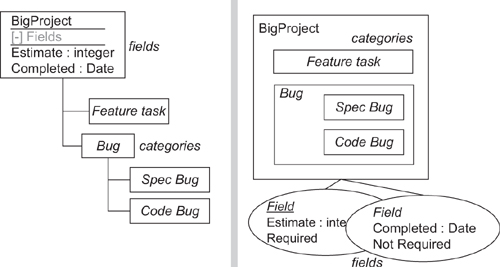
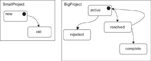
2. Projects are represented by containers, with the states inside. Since a connector from the container to the initial state would look slightly odd, we mark the initial states distinctively instead, as shown in Figure 11-12. A disadvantage here is that multiple projects with complex state diagrams will take up substantial screen real estate.
Figure 11-12. Projects contain states
3. Each project is represented by a separate model (in a separate file). Again, we mark the initial states distinctively (Figure 11-13).
Figure 11-13. One project per model file

4. As scheme 3, but with one last refinement: Initial state is marked by a separate start mark rather than a decorator on the state, as shown in Figure 11-14.
Figure 11-14. One project per model file

A benefit here is that it is slightly easier to read if we decide to allow more than one starting state—in that case, there would still be one start marker, with more than one pointer to states. It’s also in tune with standard notion for statecharts.
CJKW chooses scheme 4.
Reviewing the Domain Model
To make this notation work the following must be there:
• The Project domain class is removed, because each model corresponds to a single project.
• The mapping from domain model to drawing will be easier to define if states all embed directly from the root element (rather than some being embedded in states, as in the draft model).
• A separate relationship between states is required to represent the transitions. This should be a reference relationship.
• To provide for the start mark, we need a separate type of element. It must have a unique qualifier/key pair among the other states.
We therefore arrive at the model in Figure 11-15.
Figure 11-15. Refactored Issue State domain model
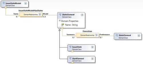
Again, there is one more improvement we can make concerning relationships among the multiplicities. As it stands, the model permits start elements to have multiple relationships to other states; we really want to allow only one transition to leave a StartElement. We could enforce this condition with validation constraints, but it is more effective to impose a hard constraint by using relationship inheritance, as shown in Figure 11-16.
Figure 11-16. Refactored Issue State domain model using relationship inheritance

Familiar Notations
You are often quite soon aware of what your notation should look like. Why did CJKW hit on statecharts for defining state transitions? Well, statecharts are such a familiar notation with a long history that it would be difficult not to. A starting template for statechart-like languages is provided with the DSL Tools, and creating the DSL is the work of an afternoon—although as we’ve seen, the framework that implements it is the time-consuming part. Of course, this used not to be the case—developing a graphical designer for a DSL used to be a big deal, before kits like the DSL Tools became available.
One of the objections sometimes raised against DSLs is that each new recruit has to learn an unfamiliar set of languages. This seems not to be a problem in practice. A clear notation adopting a familiar style is easy to pick up even if the details are different, and the constraints imposed by the toolbox and the validation conditions help to guide the newcomer. Even with textual languages, which can be much more complex than graphical ones, the user can be prompted by IntelliSense. In the end, learning a project’s DSLs are no worse—and can be a lot easier—than learning an API, and unlike the API, the DSL can be accessible, if appropriate, to end users.
Adopt any notation that is already in use in the target domain, adding information if necessary. This has the considerable advantage of improving communication with your clients. To take a completely different example for a moment, supposing you write a navigation system for the London Tube; installed on a mobile phone, it will tell you the best route from any station to any other. Now suppose you make it generic—it can work for the Paris Metro, the New York subway—potentially, for any train system anywhere. But to work for a particular train system, it has to be parameterized, using a DSL to tell it about the stations and connections. Now what would the DSL that would help you convey that information to the navigation software look like? Of course, it looks like the subway map—the shapes and connectors it defines should allow you to create models that look just like the maps of the train systems you are trying to describe.
Tip
Before constructing a concrete syntax from first principles, look to see what existing notations present themselves.
Defining Validation Constraints
Not all models that could be drawn in our language make sense. For example, it would not be useful if there were some states in an Issue State diagram that could not be reached from an Initial state.
Now that we have a domain model and notation for a DSL—at least a first draft—we should define validation constraints over the model. They will be checked when the user opens or saves the model, or explicitly asks for validation.
There are two objectives. The first is to minimize errors in tools that read the model. For example, since we generate a typed access API for Issue Fields, each field name must be a valid C# property name. A valid model is one that raises no errors when processed, so validation constraints should be determined with those tools in mind.
The second objective is to detect errors by finding inconsistencies. To this end, it can be useful to introduce redundancies into the language. For example, we could give Issue State an “End State” flag; the language user must set the flag for states that intentionally have no exit transition. This would help avoid unintentional loose ends.
Internal Consistency
Internal consistency means validation checks that can be performed on a model without reference to any external data. The following heuristics will help you discover constraints that should be written:
• Print a copy of the DSL’s domain model (with all properties visible). Link in pencil all occurrences of the same class.
• Look for loops in the resulting diagram. The loop may involve any number of links—either relationships or inheritance. For each loop, draw an example set of instances, as they would be in the internal store. Ask yourself whether corresponding loops are disallowed or mandated in the instances. See Figure 11-17 for an example.
Figure 11-17. Loops in project definition model
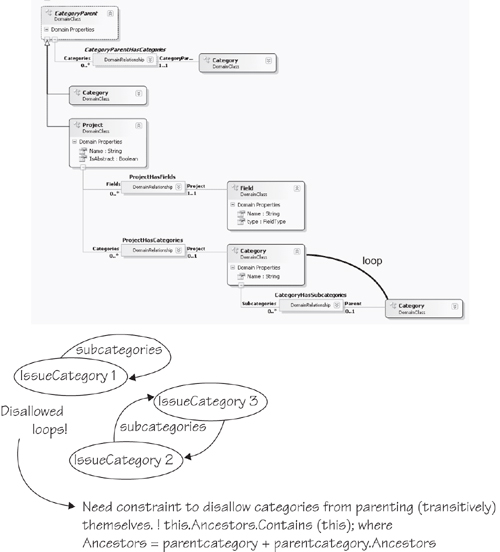
• Consider also branches off any loop, where the loop end of the branch has a multiplicity greater than 1. See Figure 11-18 for an example.
Figure 11-18. Loops in Issue State model

(Although this example serves to demonstrate the technique, our scheme to present each project’s states in its own model—hence all states are directly embedded in a single root element of domain class IssueStateModel—means this particular constraint will not be broken without a software fault.)
• Consider whether each property should be unique in some scope, for example, Field.Name in the Field’s Project.
• Consider whether there are format and range constraints for each property—may it contain spaces? May it be empty? Must it be a valid C# name?
• Consider whether each property should be constrained by the value of other properties. Equal? Not equal? Equal to some function? In some range or type?
Consistency with External Data and Models
A model must also be consistent with external data. For example, each issue state may refer to a field defined for the project in the separate project fields model. Validation checks can be written to check directly against the other model or against the database they write to.
Most external checks are for validity of reference pathnames, items in databases, and so on. It is also possible to conduct the loop-checking exercise presented earlier by drawing instance diagrams that extend beyond the boundaries of your model and drawing references of any sort—names, URIs, database keys, and so on, as lines.
Developing and Evolving the Framework
Generation versus Interpretation
The biggest task in adopting a domain-specific development approach is in generalizing the software to produce a framework. Designing and implementing a DSL is now a relatively small amount of work, thanks to kits like the DSL Tools. In the typical scenario, as we’ve discussed, the project to create a product line has been preceded by a series of more specific products. Since the team’s ideas about requirements and architecture have been evolving during that time, much of the implementation may be inconsistent between the specific instances, even where the requirements were similar. The task now is to bring them all together and separate out the necessarily variable parts from the invariant parts. Some of the variable parts may be driven from a DSL.
The project to develop the framework often coincides with a desire to rewrite the whole thing from scratch. If you have time, confidence in, and agreement on the new architecture, and confidence in continuing demand for your product, then great—have fun! But the “Big Rewrite” is always something of a risky project and usually has to go on in the back room while short-term needs are met using the old architecture. So it isn’t always acceptable for the generalization project to be a major upfront investment.
There are two broad approaches to generalization that boil down to a difference in binding time: interpretation and generation. In frameworks that implement an interpretive approach, the metadata about the variable aspects of the requirements is stored live within the system. The CJKW Issue Tracker is essentially interpretive; the names and types of fields attached to the issues in each project are held in a table, and the core of the system is independent of them. In generated systems, the metadata is used to generate code from templates at build time. A mixed approach is often used.
Let’s look at the relative advantages of the two approaches.
Performance
Interpretive systems are generally slower, both because they need to read the metadata as they go along and because they cannot be optimized to take advantage of particular configurations. In the Issue Tracker, all types of custom field value must be converted to and from a common form, and their types must be looked up in the field type table.
Upfront Investment
A generator template can be written by taking an existing instance and inserting parameters wherever there are points of variance; indeed, it’s almost impossible to do it any other way. You can start with something that covers just a small range of variation from the initial instance and then gradually elaborate the template, adding branches where you need radically different structures or algorithms in the runtime system.
In contrast, to write an interpretive system, you must first invent a core data structure that will accommodate the whole range of cases.
For example, in a generated version of the Issue Tracker, the code and structures for custom fields would be stamped out from a loop in the template to work in the same way as the standard fields (such as priority and milestones). In the existing interpretive code, custom fields are kept in a separate table while the standard fields are dealt with relatively economically as columns in the main issue table.
Flexibility and Migration
Interpretive systems are able to change on the fly and can run multiple cases side by side within the application. In the issues database, it is relatively easy to accommodate several projects with different sets of custom fields. In a generated system, a separate module would be required to support each variation, and the system would have to be stopped and rebuilt.
Interpretive systems usually handle migrations more easily. For example, suppose we add more custom fields to a project in the issues database. In an interpretive system, the field values are kept in a generic table whose form will not change with the additional fields. It is therefore easy for the code to cope with the missing fields in old issues that predate the change—a generic mechanism for filling in default values will work for them all.
But in a generated system, we might well build the set of fields more intimately into all the data structures. The issues table in the database would have a column for each field; we would have to explicitly migrate old issues into the new database.
Range
In a generated system, data structures and algorithms can be varied radically to suit the metadata simply by changing the generators. In an interpreted system, each time you stretch it to accommodate a more general structure, you may lose performance and complicate the architecture.
For example, supposing we decide that, in addition to single-valued fields, we would like lists—so that the project administrator could decide that each issue can have, say, a list of owners. This is a change that goes outside the current range of the interpretive system. We need to rewrite the generic code and data structures. The table of field types, for example, will need a flag indicating whether it can be multivalued; and since (field_id, issue_id) no longer form a unique key to field values, we may need to change the values table.
Once the change has been made, the new structures and code underlie all the data in the generic architecture. The old database will need to be migrated to the new generic structure—even those projects that don’t need the new feature. Any performance penalty applies equally to all the data.
In contrast, in a generated system, the new structures only apply where they are needed, and old databases that don’t require the new features don’t have to be migrated.
So the flexibility of interpretive systems applies only within the range that they are built for, and extending that range may require significant investment and could lead to the customization pit discussed in Chapter 1. So where the range of requirements is wide and liable to change, generation can be a better strategy.
Typing and Programmability
Compile-time type checking is one of the benefits of generated code. Even in a largely interpretive system, it can be useful to provide a generated wrapper. From the Project Definition language, we generate code that accesses untyped objects from the generic issues database and casts them appropriately. In the same way, much of the generated code in the DSL designer solution takes the form of wrappers and constructors; the underlying in-memory store provides a generic relational model in which type information is interpreted on the fly.
Typed code is much easier to write and read than the corresponding generic version. Compare “bug.Estimate” with something like “bug.GetCustomFieldValue(“Estimate”))”—the first version is not only more succinct, but the IDE helps you write it.
Evolving a Generic Framework
As we’ve seen, the quickest way to start generalizing a system can be to turn its existing code into templates and parameterize it piecewise. However, you need to very quickly start moving boilerplate into a common framework core in order to prevent the code generation code from becoming overly complex. For example, early versions of the DSL Tools had a lot of functional code generated from templates in the designer solutions. As we gained experience, more of the functionality was moved into a generic utility layer and then into the core framework.
Once you have a framework, we can envisage a number of different typical evolution paths for it. The path taken depends on initial circumstances, the stability of the requirements, and performance requirements.
Increasing Genericity
In this scenario, the code of a product line starts with one or two specific instances and then works through a number of template-generated versions in which there is an increasing set of variation points. Then boilerplate from the template is moved into the framework, and the generation templates are simplified. Finally, it moves toward an interpretive system tailored to the range of expected requirements, but it retains a layer of generated strong-typing wrappers. This happens cyclically and incrementally, so at any point in time there may be some parts of the framework that are interpretive and some that are refactored boilerplate.
Prototypes
In this route, there are more funds for upfront experimentation with the architecture. The project may begin with some small specific instances, but then it goes straight for an interpretive architecture, with a long period of design. Part of the rationale is that the result will be easy to experiment with on the fly. In practice, the range of cases covered is likely to match the actual requirements rather imperfectly (especially if the requirements are changing in the meantime), and so the initial version will be over-elaborate in some areas and difficult to stretch in others. For example, we might have started with an issues database that could handle multiple types of link between issues—which might never be needed—but doesn’t deal with more than one type of issue per project, which probably will be needed.
Integrated Systems
If you are lucky, you have access to the source code of the whole system and can make choices about where on the generative-interpretive axis it lies. More often, though, systems are constructed from an ill-matched collection of existing parts for which there is no source code. In this case, all you have control of is a miscellany of configuration files and bits of plug-in code. Making a change at the requirements level involves multiple changes in these diverse pieces.
This is one of the great strengths of generative architecture—it provides a method of abstracting the actual requirements from these implementation details.
The degree to which the metadata is interpreted in the live system is determined by the components themselves, and it may differ between the components. For example, the Issue Tracking database is interpretive; from the Project Definition and State Transition designers, we generate SQL that transfers the metadata into the database. This metadata can be updated on the fly without harming the existing instance data or stopping the system. However, the type wrappers are compiled from generated code, so a client that uses them must be stopped when the metadata are updated.
Driving a Framework from the DSL
There are at least three ways of driving a framework from the DSL. These have already been considered in depth in other chapters, so we just provide a summary here:
• Model as configuration file. The model is serialized to a file; the generic framework reads the file on build, or in a setup operation. Variants of this involve adjusting the serializer to suit an existing framework, or processing the file with XML tools. Serialization was discussed in Chapter 6.
• Model generates code. In Visual Studio, the model is one file in a project; the project also contains multiple templates that read the model, generating code and other files. Templates are transformed before building, and most changes to the code are made by adjusting the model. When necessary, some custom code is added. Rarely, some change is needed to a template file. This is the architecture used by the DSL Tools for authoring DSLs and their designers and associated components. This was all discussed in Chapter 8, which also provided a sample of how to drive the Text Templating Engine from a command in order to provide more orchestrated generation.
• Model drives external API. A command associated with the DSL reads the model and drives a database or other system. The model may be entirely transferred into the external system by the operation, or it may update just relevant parts of the system. This would be used by the Issue Tracker to update the database from the model, for example. The implementation of custom commands was described in Chapter 10.
Tip: Custom commands in Visual Studio
The approach to adding custom commands uses the raw Visual Studio extensibility mechanisms. Another possibility is to use the Visual Studio Guidance Automation Toolkit,4 with which it is also possible to attach commands to DSLs—as well as other parts of the Visual Studio UI such as particular types of project and project item—and have them instantiated along with code files and templates in a project.
Testing
Automated tests are a very successful assurance against the introduction of errors as code is extended and refactored. Tests typically include
• Unit tests aimed at individual pieces of code written by the unit’s developer, and including “mock” or stub interfaces to simulate the rest of the system.
• Integration, or “end-to-end” tests, which take the system through scenarios at the user level and are designed to verify that the system requirements have been met.
• Combinatorial tests designed to try significant combinations of input values, particularly edge cases, to check correct behavior throughout the space and to check error handling.
• Performance tests that check capacity and response times.
There are several aspects of a DSL that need to be tested: validation constraints; generator templates; any generated code; menu commands; anything you have customized, such as serialization; and the DSL itself.
Tip: Automating Tests
Visual Studio Team System provides a good automated test framework that allows a developer to run unit tests on his or her project before checking in changes to the shared repository. There are also command-line utilities that build a VS project and run its tests, which can be used in an unmanned nightly or rolling build system (which continually tests the latest repository content). We divide up our development into tasks of a few days each and find these facilities invaluable for preventing regressions.
Tip: Measuring Code Coverage
Visual Studio’s test kit includes a coverage tool, which monitors tests as they run, marking and counting the number of branches executed within the code under test. A typical expectation is that a suite of automated tests should achieve coverage of at least 70%–80%5.
After a test has run within VS, you can right-click and select “Code Coverage Results,” and get a view of the source code in which the executed branches are highlighted. This helps you adjust your tests to make sure most branches are exercised, which gives some assurance that the most common paths (the combinations of branches through the code) have been checked.
To get a coverage analysis, you first identify the compiled assembly to the coverage tool, under the “Test>Edit Test Run Configurations” menu in Visual Studio.
Validation Constraints
Your validation constraints should generate warnings for any invalid combinations of objects, properties, and links. In particular, any generators or other tools that process your models should be able to correctly process every model that passes validation.
A straightforward approach to validation tests is to hand-build one or more test models, with examples of each kind of error, as well as a representative selection of valid elements.
Validation tests can be automated from within a unit test by creating or loading test models and then calling validation through APIs.
Tip: Create test models in code rather than reading them from a file
You could create test models by hand, and then have your automated tests read these in. But it is more flexible to write code that constructs a model instance in memory—when the DSL changes, it is quicker to change the code than to change the test models. Chapter 3 explained how to create models in memory. If you want to share the code between multiple tests, then put it in a helper class that all tests can access.
Tip: Use validation base classes for unit tests
Chapter 7 explained how to use validation outside the IDE by using the ValidationController, ValidationContext, and ValidationMessage base classes directly. This approach can be used within unit tests to validate a model created in memory, with the error messages being passed to a log file that can then be compared to a baseline.
The test can dump the error list to a text file and compare it with a baseline (that is, a previous example of the same list that you have checked by hand). On the day some change alters the list of reported errors, the test will fail; the developer must either fix the fault or confirm that the new results are OK by copying them to the baseline file.
Your test models must also produce sensible results when your generation templates, custom commands, and any other tools are run against them. Models used to check these tools should therefore be checked to see that they pass validation; conversely, any test models that pass validation should be checked against the other tools.
Tip: Use snapshots to create test cases
We earlier described how snapshots could be used to help design the domain model, and, indeed, validation constraints on that domain model. Snapshots provide a pictorial view of instances of the domain model, and the test cases for a validation constraint are, essentially, a set of domain model instances, some of which satisfy the constraint and some of which don’t (counterexamples). So start with any snapshots that you created when working out the constraint in the first place, and encode those as test cases. Then create new snapshots to give increased coverage, paying particular attention to counterexamples (which will cause errors).
Generator Templates
You need to test your generating templates, which need to work with any model that passes the validation tests.
Once again, a straightforward method is to create one or more test models by hand. Then you run the template within Visual Studio using “Run Custom Tool” or “Transform All Templates,” and check the generated result. For an automated test, you can either drive Visual Studio through its API or use the command-line interface to the text templating engine (which doesn’t require VS). The test should compare the result with a baseline.
Before comparing against a baseline, you usually need to recognize and blank out some things that can vary from one run to another—Guids are a particular culprit, and Dates if they are initialized from “now.”
When testing templates, we only want valid models. A possible starting point is to use the valid models created to test validation. Also, if you find that you are able to generate code that doesn’t build from these models, it probably means that you’ve omitted a validation constraint. It is better to add a further validation constraint rather than write code in the template that looks for the invalid model and writes an error message to the output.
You can get a coverage analysis of a text template, but there are some complications. The text templating engine translates your template into a temporary C# file, and then compiles and executes it; the compiled code reads your model and writes the result file. Then the engine will normally delete both the temporary C# file and the compiled assembly. To get a coverage analysis, you need to be able to identify the assembly to the coverage tool, which entails precompiling the text template and keeping the translated source and compiled assembly afterwards so that you can see the analysis.
Generated Code
If your generator templates create code, or data files interpreted by code, you will want to test their behavior. A generated file will usually be part of a project containing several other generated or fixed files, just as the DSL Language project itself is. Generated code tests follow this sequence:
1. Create a copy of a project in which code generated from the templates is used.
2. Substitute the model file with a test model (which must be valid).
3. Execute the project’s templates (either through the command-line version of the text templating host or by driving VS to run the “Transform All Templates” command).
4. Build the project (using MSBuild from a script or using the VS API).
5. Run the behavioral tests on the built assembly. (What the tests do depends on the nature of the project.)
6. Repeat from step 2, with another test model.
An alternative would be to generate both the target product code as well as unit tests for that code and then run the normal unit test and code coverage tools from Visual Studio.
Rules
Rules are used to maintain consistency across a model, propagating changes from one part to another. They were introduced in Chapter 3, used in Chapter 7, and discussed in more depth in Chapter 10. A rule can be tested in an instance of the DSL Tools Store, without running Visual Studio, by creating a model, making a change within a transaction, committing it (thereby causing rules to fire), and then checking that the resulting model incorporates the expected changes caused by the rules. This can be automated in a unit test using some of the techniques already described.
Language Definition
Does the DSL cover all the information your users need to capture? If you followed the method earlier in the chapter, you developed the language from specific requirements scenarios. But as you experiment and change the DSL, it is worth retrying those scenarios at intervals to ensure that you don’t drift away from them. This is a manual test, because it depends on your judgment about the usability and scope of the language.
Evolving a DSL
After designing and using a DSL for a while, you will inevitably want to change it, and you will not want to lose the language instances that you have already created.
Changes in a DSL take one of the following forms:
• Additions. New properties in a class or relationship; new classes; new relationships. The deserializer will take care of these, filling in default values when reading objects from older files.
• Deletions. Properties, classes, or relationships removed. In this case, the deserializer will ignore the deleted elements.
• Refactoring. A structure is replaced by something that represents the same information in a different way. For example, we might replace the Issue State Transition by a class with a pair of relationships on either side. Here, the deserializer will see some additions and some deletions but will not be able to do the translation automatically.
• Changes of property and relationship types come under the refactoring heading.
Of these, the language author needs to worry about refactorings. The following tactics mitigate the pain of change to some extent:
• Separate refactorings. Identify and localize each refactoring, and plan separately how you will deal with each one. For example, one version change of the Issue State DSL might introduce a domain class to replace the Transition relationship, and might also introduce multiple issue types per project. As far as possible, we should keep those changes independent of each other.
• Don’t delete anything. Instead of deleting the old structure, just add the new one—for example, have both the Transition relationship and the domain class replacing it coexist in the same model. Deprecate the old structure by removing its tools from the toolbox, and any merge directives or connection builders that might deal with its creation, so that new instances can’t be created. Then use one of the tactics that follow this one.
• Ensure the tools work with both structures. During a migration period, ensure that the generating templates and other tools can work with both structures as much as possible. If the change is prompted by a changed requirement in what the tools generate, at least allow language users to edit and work with the old instances until they need to generate material from them.
• Provide translation tools. One way is to provide a command that scans a store and updates the model in place. It is possible to make this happen on opening a file of an older version.
Another convenient method of translating instance models is to write a generating template that creates the serialized form of the new version of the DSL from models of the older version.
XSLT can also be used to translate one model file into another, given that they are both XML files.
• Validate required fields. If you translate on opening an old file, make sure that your validation methods check any new fields so that the user is prompted to provide the required extra information.
• Delete obsolete domain classes when you’re sure all the instances are updated.
• Publish the update plan to your language users so that they know when older structures will be obsolete.
Migration between language versions is an important and common problem. Having a forgiving file reader (deserializer) certainly relieves some of the pain, but you could do more. It is possible to conceive of tools that automate some of the above tactics. For example, one could maintain the history of changes to a domain model between versions and then use this information to generate a tool that does the conversion automatically.
What Makes a Good DSL?
A good DSL—one that helps the people who are using it—makes it easy to clearly represent information for a particular purpose. The following are some characteristics of a good DSL, many of them summarizing what we’ve discussed already:
• Well-defined scope. There is an easy-to-state single purpose for the DSL—for example, “to describe the permitted sequence of states of issues in a project.”
• Minimality. There are no more concepts and relationships than are required for the ideas that need to be described with the DSL. If you can see a way to reduce the number without losing information, do so.
• Familiarity. If there is a notation already in use in the domain—railroad tracks? electrical circuits?—base your notation on that. If the type of information is normally associated with a particular style of diagram—statecharts—use the conventions familiar there. Adapt the notation where you need to.
• Bring out the important bits. The most important things should be the most obvious and easiest to change: names of states, transitions between them. Less important detail—for example, the target namespace of the generated code—can be left to the properties window. If you need to print out the full detail for some reviews, write a report template.
• Moderate amount of redundancy. Ensure that when the user has made an important distinction, it was intentional. For example, we flag an error if the user has not marked a state with no incoming transitions as “start.” On the other hand, users don’t like to have to say everything twice, so don’t overdo it.
• Use the syntactic space. Most of the diagrams a user can draw should be meaningful. A language that is heavy with complex constraints probably doesn’t fit the conceptual space well and is difficult to remember how to use. The big advantage of a DSL is that the notation guides you through useful things to say.
• Graphs are not syntax trees. If you have an existing text notation, it is unlikely that its syntax tree will be the best graphical notation. See the example on regular expressions in the next section.
• Allow for customization. Your DSL will not cover all the cases that users will require. Provide for further customization through hand-written code, preferably without forcing the users to alter generating templates.
• Use the users’ language. The language should be expressed in its users’ terms, talking about their requirements—rather than its implementations. Talk about issues rather than tables. Where it’s difficult to avoid bringing in some implementation concerns, try to package them up in a single domain class, or by exploiting categories in the properties window (see the end of Chapter 4). For example, in the DSL designer you’ll find that properties that are mostly concerned with the form of the generated code are always gathered together under a “Code” category.
To illustrate the last few points further, we will consider the development of a different example.
Appropriate Notation: An Example with Regular Expressions
As software designers, we are always strongly aware of the tree-structured nature of just about everything we deal with. In designing a DSL notation, there is always an inclination to represent this tree directly in the syntax. However, this is not always the most usable option.
Chapter 1 mentioned regular expressions as an example of a textual DSL. Regular expressions have a very compact textual notation, and while very powerful for those who have learned the notation, occasional users can find them opaque. The goal in this example is to create a DSL in which regular expressions can be constructed with a graphical notation. The expected benefits include
• The toolbox guides construction of the expression.
• A pictorial model is easier to follow.
• Validation checks can be applied.
• Graphical presentation should be easier to learn and understand.
Reminder about Regular Expressions
Regular expressions can seem very arcane to the uninitiated, but the basic idea is simple. Suppose you are processing some text—let’s say, an html file; and you want to find the next html element (between < and >); and you want to extract the tag and the parameter pairs of the element and get them into separate variables. So you call:
foreach (Match m in
Regex.Match(yourHtmlString, theRegularExpression))
{ ... and each m is a match to part of the string ... }
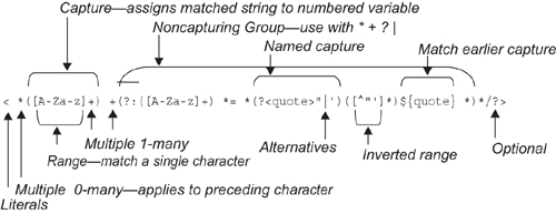
The regular expression contains a sequence of characters that you expect to find in the string, and certain characters (parentheses, * + ? [ ] and one or two others) play special roles. * signifies a repetition of zero or many of what went immediately before, so that < * matches a < followed by any number of spaces, including none. + is similar, but insists on at least one occurrence. Square brackets match any single character in the range defined within, so that [A-Z]+ matches any sequence of at least one capital letter. Parentheses demarcate a match that you wish to capture into a variable, so that ([A-Za-z]+) should return to you a word made of one or more alphabetics. (?:...)* repeatedly performs the matches within the parentheses without capturing the whole thing to a variable. | specifies alternative matches. (?<name>...) matches a pattern that a later ${name} must match in the same way—so that the use of quote in the following example ensures that an opening quotation is matched with the same kind of closing mark.
This regular expression:
< *([A-Za-z]+) +(?:([A-Za-z]+) *= *(?<quote>"|')([^"']*)${quote} *)*/?>
matches, for example:
< table bgcolor= "#ffddff" border="1' >
as illustrated in Figure 11-19.
Figure 11-19. Interpretation of a regular expression
The objective of this DSL is to make a more accessible notation for regular expressions.
Candidate Notations
There are several notations that might be made to work, each of which takes a rather different approach. One of our major principles is to work from instances, so in the following we use an example that teases out the notational distinctions: <a (?:b[cd]*e|[a-z]+)z.
Candidate Notation 1: Regexp Tree
This notation (Figure 11-20) directly represents the abstract syntax tree of the regular expression. A sequence is represented by a vertical box, iterations are shown as a “*” in a circle, and alternatives are shown as a “|” in a circle.
Figure 11-20. Regexp Tree notation

The difficulty is that it isn’t very easy to follow how it matches up to a given input string. For one thing, you have to go back and forth between nodes and their descendants to follow the matching process.
Candidate Notation 2: Railroad Tracks
“Railroad tracks” (Figure 11-21) have been used for presenting parsing paths for many years (notably in the syntax definition of Pascal). Match by pushing a counter around as you follow the string; replicate the counter on going through a branch (small filled rectangle); delete a counter when it fails to match; the whole thing matches if you get a counter to the end.
Figure 11-21. Railroad track notation

The big drawback to this notation is that there are a lot of possible graphs that don’t correspond to regular expressions. While it is possible to write validations, contraventions are not always easy for the naïve user to spot, and it would be very irritating to constantly run into obscure error flags. In general, one of the expectations of a DSL is that it helps you to make statements that make sense within the domain.
The particular difficulty is that it allows you to make non-nested loops, and it can be quite difficult, depending on the layout of the graph, to see whether the constraint has been contravened or not, as illustrated in Figure 11-22 (which is invalid).
Figure 11-22. Invalid railroad track
Candidate Notation 3: Nested Boxes
This is a compromise solution in which arrows represent sequence, and nesting represents containment (Figure 11-23). The rule here is that paths can only converge or diverge at the branch points on either side of a box that contains the alternative paths. Each node otherwise just has at most one arrow entering and one leaving. There are also loop boxes with ports marked * or +.
Figure 11-23. Nested box notation

This works just as well with the counter semantics while at the same time disallowing spaghetti branches. At the exit of a + or * loop box, you can move the counter around the box boundary back to the entry port. If the entry port is * or ?, you can avoid the content altogether by moving around the boundary straight to the exit. (The entry ports are decorated with arrows lined up with the box boundary to suggest this behavior.)
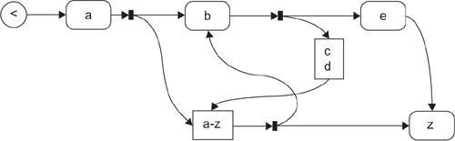
Candidate Notation 4: Nested Paths
This is another counter-following notation, but there are two kinds of link. Each node only has one entering link (Figure 11-24). To match a string to the expression, you follow the Next links, matching each character to the character in a box; if you match the last node to the string, the match has succeeded. If you come to a diamond or circle, you must first follow its Parts links, and match that (by getting to the last link)—if there are several Parts links, split the counters and a match to any one will do.
Figure 11-24. Nested path notation
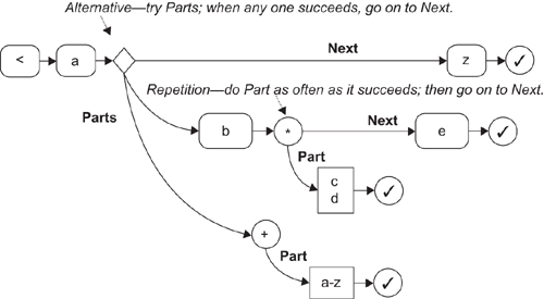
This notation is a bit more difficult to follow than the nested boxes, but (unlike candidate 2) all of the graphs you can draw make sensible regular expressions, and (unlike candidate 1) sequences of matches are represented by following Next links rather than working through a fan of sibling links so that you can understand the graph by pushing counters around it.
Graphs Are Not Syntax Trees
Nested Boxes (or its pragmatic variant, Nested Paths) seem to be the best notation, but notice how far those notations are from the initial direct representation of the regular expression syntax tree. The first candidate would be the easiest to generate regular expressions from, but the better notations help a user to understand the concepts.
The same consideration will frequently apply when taking any existing text syntax—typically an XML file—and creating a diagrammatic representation of it. The syntax tree of the existing language is often not the best option.
Summary
This chapter has presented a set of techniques and options around the process of designing DSLs for domain-specific development, picking up where we left off in Chapter 2 and benefiting from a much deeper knowledge of the mechanics of creating a DSL and associated code generators (Chapters 3–10).
On the topic of identifying variability, we summarized the top-down versus bottom-up approaches and introduced feature trees as a way for working top-down. We introduced the notion of snapshots to assist with the development a domain model, and described by example how a notation might evolve from initial ideas to the final definition, and the kinds of trade-offs that have to be made. Snapshots made a reappearance when considering how to identify and define validation constraints; we also identified some domain model patterns to watch out for as indicators that additional constraints may be required. We then moved on to the topic of frameworks, where we discussed more pros and cons of generation versus interpretation, and we provided some advice on evolving them. That was followed by some advice on how to go about testing a DSL and code generators, with cross-references to other parts of the book that have introduced coding techniques relevant to writing automated tests. There was then a brief section on what to watch out for when evolving a DSL, and tactics you can use to mitigate the pain were presented. The chapter concluded with some advice on how to recognize a good DSL, illustrating this with a comparison of possible graphical notations for regular expressions.
Conclusion
So you’ve downloaded the tools, read the book, and you’re gung ho on implementing a domain-specific approach to development in your organization. What’s the best way to go about this? Our advice would be to start small and bottom-up. Find a project where you reckon there’s a lot of repetitive code being written, templatize it, and write a DSL to drive the templates.
As you start to scale, you’ll probably need to orchestrate your code generation, for example, loop though a model and generate one file per model element. In Chapter 8, we described how, with some custom code, you could go about this—and the technique will take you some distance. However, you might also like to look up the Guidance Automation Toolkit (GAT)6, which can be used for code generation orchestration as well as for automating other development tasks like unfolding project templates. GAT adopts a strategy of revealing automation steps to the developer in context and at the point that the developer needs them.
Once you’ve got two or three DSLs going, or even as you start to develop the second, you may find it necessary to get different DSLs to interact. For example, you may need to know how to have elements in a model of one DSL cross-reference elements in a model of another DSL (or even cross-reference elements in another model of the same DSL), to navigate those references in the UI, to know when the references are broken and be told how to fix them, and to visualize the references on the design surface. And then you will need to know how to exploit these cross-references in activities such as code generation and validation. It is possible to implement some of this yourself through custom code—a starting point would be, for example, storing cross-references as strings in properties on domain classes—and we are aware of customers who have done this. There is also a powertool available called the Designer Integration Service (DIS),7 which can be downloaded for experimentation purposes, though it is not suitable for production tools.
At some point, you’ll also need to integrate domain-specific development with your organization’s general software development practices. We’re not going to pretend this is an easy task, because it is likely to have significant impact on the development culture of the organization. Take, for example, the job of specifying the application to be built. You may find that the models you are producing, and from which significant code is being generated, don’t need developer expertise to write down (at least not the initial drafts), and, further, that they could replace large tracts of informal specification. If that’s the case, the specification task changes into one of defining the models that then get passed on and further refined by the development team, and then writing informal specs for those aspects that still need to be implemented as custom code. Are those who write specifications in your organization willing or able to change the way they work? There’s also an impact on testing; if the code generators are tested, what aspects of the generated code that is embedded in the system being built needs testing? How does this impact the testing process familiar to the testers in your organization? The developers will also have less code to write, in particular, less rote code. This may suit some developers, but for others it may take them into uncomfortable zones—writing rote code is how they make a living. And what about the impact on the project planning process? What are the costs of specification, development, and testing when models and code generators are involved? Our best advice is to work very pragmatically and incrementally—do it a project at a time; take metrics (e.g., estimated versus actual cost) to inform the next project; get buy-in from a few individuals in different disciplines and then roll it out from there; and build up a wiki of best practices, maintain it, and share it between projects.
So you’ve read the book and want to read more? What can we recommend? Just one book: Software Factories: Assembling Applications with Patterns, Models, Frameworks and Tools, by Jack Greenfield and Keith Short, with Steve Cook and Stuart Kent.8 This book synthesizes a number of recent initiatives in software development (e.g., product lines, model driven development, domain-specific languages, patterns) into a theory for software development in the future and elaborates that theory in some depth. One can think about domain-specific development as a stylized form of the software factory approach, and the Software Factories book will certainly get you thinking about how it might evolve. Also, being a book of synthesis, it has a rich bibliography for those who wish to delve further.
Our job here is done. Our goal in writing this book was to explain what Microsoft’s DSL Tools are for, and how to use them effectively. If you were already a user of the DSL Tools, then we hope this book has provided some useful new techniques to try out on your own projects, and clarified any aspects you didn’t understand. If you’re new to the DSL Tools, we hope the book has inspired you to download the tools and try the approach for yourself.